Application of First-Order Shear Deformation Theory on Vibration Analysis of Stepped Functionally Graded Paraboloidal Shell with General Edge Constraints


Abstract
:1. Introduction
2. Fundamental Theory
2.1. The Description of the Model
2.2. Energy Equations of Stepped FG Paraboloidal Shell
2.3. Displacement Functions and Solution
3. Analysis of Examples
3.1. Convergence Analysis
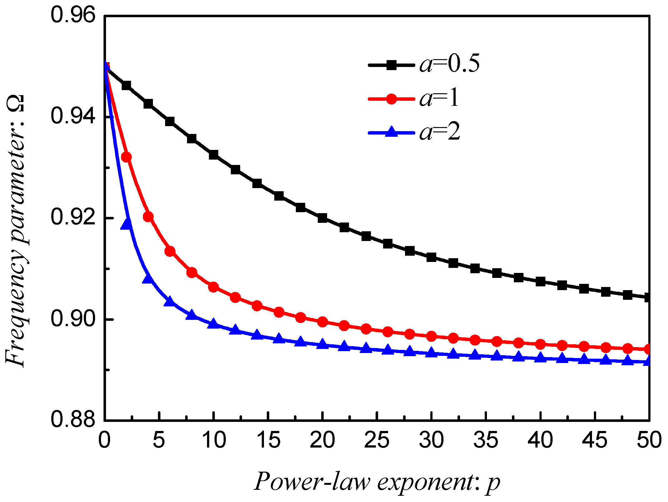
3.2. Free vibration Behavior of Stepped FG Paraboloidal Shell
4. Conclusions
Author Contributions
Funding
Conflicts of Interest
Appendix A
References
- Fantuzzi, N.; Brischetto, S.; Tornabene, F.; Viola, E. 2D and 3D shell models for the free vibration investigation of functionally graded cylindrical and spherical panels. Compos. Struct. 2016, 154, 573–590. [Google Scholar] [CrossRef]
- Tornabene, F.; Reddy, J.N. FGM and Laminated Doubly-Curved and Degenerate Shells Resting on Nonlinear Elastic Foundations: A GDQ Solution for Static Analysis with a Posteriori Stress and Strain Recovery. J. Indian Inst. Sci. 2013, 93, 635–688. [Google Scholar]
- Pradyumna, S.; Bandyopadhyay, J.N. Free vibration analysis of functionally graded curved panels using a higher-order finite element formulation. J. Sound Vib. 2008, 318, 176–192. [Google Scholar] [CrossRef]
- Jouneghani, F.Z.; Dimitri, R.; Bacciocchi, M.; Tornabene, F. Free Vibration Analysis of Functionally Graded Porous Doubly-Curved Shells Based on the First-Order Shear Deformation Theory. Appl. Sci. 2017, 7, 1252. [Google Scholar] [CrossRef]
- Chen, H.Y.; Wang, A.W.; Hao, Y.X.; Zhang, W. Free vibration of FGM sandwich doubly-curved shallow shell based on a new shear deformation theory with stretching effects. Compos. Struct. 2017, 179, 50–60. [Google Scholar] [CrossRef]
- Wang, Q.S.; Cui, X.H.; Qin, B.; Liang, Q.; Tang, J.Y. A semi-analytical method for vibration analysis of functionally graded (FG) sandwich doubly-curved panels and shells of revolution. Int. J. Mech. Sci. 2017, 134, 479–499. [Google Scholar] [CrossRef]
- Wang, Q.S.; Qin, B.; Shi, D.Y.; Liang, Q. A semi-analytical method for vibration analysis of functionally graded carbon nanotube reinforced composite doubly-curved panels and shells of revolution. Compos. Struct. 2017, 174, 87–109. [Google Scholar] [CrossRef]
- Wang, Q.S.; Cui, X.H.; Qin, B.; Liang, Q. Vibration analysis of the functionally graded carbon nanotube reinforced composite shallow shells with arbitrary boundary conditions. Compos. Struct. 2017, 182, 364–379. [Google Scholar] [CrossRef]
- Wang, Q.S.; Shi, D.Y.; Liang, Q.; Pang, F.Z. Free vibration of moderately thick functionally graded parabolic and circular panels and shells of revolution with general boundary conditions. Eng. Comput. 2017, 34, 1598–1641. [Google Scholar] [CrossRef]
- Tornabene, F.; Viola, E. Free vibrations of four-parameter functionally graded parabolic panels and shells of revolution. Eur. J. Mech. A Solids 2009, 28, 991–1013. [Google Scholar] [CrossRef] [Green Version]
- Viola, E.; Tornabene, F. Free vibrations of three parameter functionally graded parabolic panels of revolution. Mech. Res. Commun. 2009, 36, 587–594. [Google Scholar] [CrossRef]
- Tornabene, F.; Viola, E. Static analysis of functionally graded doubly-curved shells and panels of revolution. Meccanica 2013, 48, 901–930. [Google Scholar] [CrossRef]
- Fazzolari, F.A.; Carrera, E. Refined hierarchical kinematics quasi-3D Ritz models for free vibration analysis of doubly curved FGM shells and sandwich shells with FGM core. J. Sound Vib. 2014, 333, 1485–1508. [Google Scholar] [CrossRef]
- Kar, V.R.; Panda, S.K. Free vibration responses of functionally graded spherical shell panels using finite element method. In Proceedings of the ASME 2013 Gas Turbine India Conference, Bangalore, India, 5–6 December 2013; p. V001T005A014. [Google Scholar]
- Tornabene, F. Free vibration analysis of functionally graded conical, cylindrical shell and annular plate structures with a four-parameter power-law distribution. Comput. Methods Appl. Mech. Eng. 2009, 198, 2911–2935. [Google Scholar] [CrossRef]
- Zghal, S.; Frikha, A.; Dammak, F. Free vibration analysis of carbon nanotube-reinforced functionally graded composite shell structures. Appl. Math. Model. 2018, 53, 132–155. [Google Scholar] [CrossRef]
- Kulikov, G.M.; Plotnikova, S.V.; Kulikov, M.G.; Monastyrev, P.V. Three-dimensional vibration analysis of layered and functionally graded plates through sampling surfaces formulation. Compos. Struct. 2016, 152, 349–361. [Google Scholar] [CrossRef]
- Kapuria, S.; Patni, M.; Yasin, M.Y. A quadrilateral shallow shell element based on the third-order theory for functionally graded plates and shells and the inaccuracy of rule of mixtures. Eur. J. Mech. A Solids 2015, 49, 268–282. [Google Scholar] [CrossRef]
- Hosseini-Hashemi, S.; Derakhshani, M.; Fadaee, M. An accurate mathematical study on the free vibration of stepped thickness circular/annular Mindlin functionally graded plates. Appl. Math. Model. 2013, 37, 4147–4164. [Google Scholar] [CrossRef]
- Bambill, D.V.; Rossit, C.A.; Felix, D.H. Free vibrations of stepped axially functionally graded Timoshenko beams. Meccanica 2015, 50, 1073–1087. [Google Scholar] [CrossRef]
- Vinyas, M.; Kattimani, S.C. Static analysis of stepped functionally graded magneto-electro-elastic plates in thermal environment: A finite element study. Compos. Struct. 2017, 178, 63–86. [Google Scholar] [CrossRef]
- Vinyas, M.; Kattimani, S.C. Static studies of stepped functionally graded magneto-electro-elastic beam subjected to different thermal loads. Compos. Struct. 2017, 163, 216–237. [Google Scholar] [CrossRef]
- Su, Z.; Jin, G.Y.; Ye, T.G. Vibration analysis of multiple-stepped functionally graded beams with general boundary conditions. Compos. Struct. 2018, 186, 315–323. [Google Scholar] [CrossRef]
- Li, H.; Pang, F.; Chen, H.; Du, Y. Vibration analysis of functionally graded porous cylindrical shell with arbitrary boundary restraints by using a semi analytical method. Compos. Part B Eng. 2019, 164, 249–264. [Google Scholar] [CrossRef]
- Li, H.; Pang, F.; Wang, X.; Du, Y.; Chen, H. Free vibration analysis for composite laminated doubly-curved shells of revolution by a semi analytical method. Compos. Struct. 2018, 201, 86–111. [Google Scholar] [CrossRef]
- Tornabene, F.; Fantuzzi, N.; Bacciocchi, M.; Reddy, J.N. An Equivalent Layer-Wise Approach for the Free Vibration Analysis of Thick and Thin Laminated and Sandwich Shells. Appl. Sci. 2017, 7, 17. [Google Scholar] [CrossRef]
- Tornabene, F.; Fantuzzi, N.; Bacciocchi, M. A new doubly-curved shell element for the free vibrations of arbitrarily shaped laminated structures based on Weak Formulation IsoGeometric Analysis. Compos. Struct. 2017, 171, 429–461. [Google Scholar] [CrossRef]
- Tornabene, F.; Fantuzzi, N.; Bacciocchi, M.; Viola, E. Effect of agglomeration on the natural frequencies of functionally graded carbon nanotube-reinforced laminated composite doubly-curved shells. Compos. Part B Eng. 2016, 89, 187–218. [Google Scholar] [CrossRef]
- Tornabene, F.; Fantuzzi, N.; Viola, E.; Batra, R.C. Stress and strain recovery for functionally graded free-form and doubly-curved sandwich shells using higher-order equivalent single layer theory. Compos. Struct. 2015, 119, 67–89. [Google Scholar] [CrossRef]
- Li, H.; Pang, F.; Wang, X.; Li, S. Benchmark Solution for Free Vibration of Moderately Thick Functionally Graded Sandwich Sector Plates on Two-Parameter Elastic Foundation with General Boundary Conditions. Shock Vib. 2017, 2017, 4018629. [Google Scholar] [CrossRef]
- Li, H.; Liu, N.; Pang, F.; Du, Y.; Li, S. An Accurate Solution Method for the Static and Vibration Analysis of Functionally Graded Reissner-Mindlin Rectangular Plate with General Boundary Conditions. Shock Vib. 2018, 2018, 4535871. [Google Scholar] [CrossRef]
- Zhong, R.; Wang, Q.; Tang, J.; Shuai, C.; Qin, B. Vibration analysis of functionally graded carbon nanotube reinforced composites (FG-CNTRC) circular, annular and sector plates. Compos. Struct. 2018, 194, 49–67. [Google Scholar] [CrossRef]
- Fantuzzi, N.; Tornabene, F.; Viola, E. Four-parameter functionally graded cracked plates of arbitrary shape: A GDQFEM solution for free vibrations. Mech. Adv. Mater. Struct. 2016, 23, 89–107. [Google Scholar] [CrossRef]
- Choe, K.; Tang, J.; Shui, C.; Wang, A.; Wang, Q. Free vibration analysis of coupled functionally graded (FG) doubly-curved revolution shell structures with general boundary conditions. Compos. Struct. 2018, 194, 413–432. [Google Scholar] [CrossRef]
- Zhao, J.; Zhang, Y.; Choe, K.; Qu, X.; Wang, A.; Wang, Q. Three-dimensional exact solution for the free vibration of thick functionally graded annular sector plates with arbitrary boundary conditions. Compos. Part B Eng. 2019, 159, 418–436. [Google Scholar] [CrossRef]
- Zhao, J.; Choe, K.; Xie, F.; Wang, A.; Shuai, C.; Wang, Q. Three-dimensional exact solution for vibration analysis of thick functionally graded porous (FGP) rectangular plates with arbitrary boundary conditions. Compos. Part B Eng. 2018, 155, 369–381. [Google Scholar] [CrossRef]
- Guo, J.; Shi, D.; Wang, Q.; Tang, J.; Shuai, C. Dynamic analysis of laminated doubly-curved shells with general boundary conditions by means of a domain decomposition method. Int. J. Mech. Sci. 2018, 138–139, 159–186. [Google Scholar] [CrossRef]
- Pang, F.; Li, H.; Du, Y.; Li, S.; Chen, H.; Liu, N. A Series Solution for the Vibration of Mindlin Rectangular Plates with Elastic Point Supports around the Edges. Shock Vib. 2018, 2018, 8562079. [Google Scholar] [CrossRef]
- Li, H.; Pang, F.; Chen, H. A semi-analytical approach to analyze vibration characteristics of uniform and stepped annular-spherical shells with general boundary conditions. Eur. J. Mech. A Solids 2019, 74, 48–65. [Google Scholar] [CrossRef]
- Li, H.; Pang, F.; Miao, X.; Du, Y.; Tian, H. A semi-analytical method for vibration analysis of stepped doubly-curved shells of revolution with arbitrary boundary conditions. Thin-Walled Struct. 2018, 129, 125–144. [Google Scholar] [CrossRef]
- Li, H.; Pang, F.; Miao, X.; Li, Y. Jacobi–Ritz method for free vibration analysis of uniform and stepped circular cylindrical shells with arbitrary boundary conditions: A unified formulation. Comput. Math. Appl. 2018. [Google Scholar] [CrossRef]
- Li, H.; Pang, F.; Wang, X.; Du, Y.; Chen, H. Free vibration analysis of uniform and stepped combined paraboloidal, cylindrical and spherical shells with arbitrary boundary conditions. Int. J. Mech. Sci. 2018, 145, 64–82. [Google Scholar] [CrossRef]
- Pang, F.; Li, H.; Wang, X.; Miao, X.; Li, S. A semi analytical method for the free vibration of doubly-curved shells of revolution. Comput. Math. Appl. 2018, 75, 3249–3268. [Google Scholar] [CrossRef]
- Bhrawy, A.H.; Taha, T.M.; Machado, J.A.T. A review of operational matrices and spectral techniques for fractional calculus. Nonlinear Dyn. 2015, 81, 1023–1052. [Google Scholar] [CrossRef]
- Pang, F.; Li, H.; Choe, K.; Shi, D.; Kim, K. Free and Forced Vibration Analysis of Airtight Cylindrical Vessels with Doubly Curved Shells of Revolution by Using Jacobi-Ritz Method. Shock Vib. 2017, 2017, 4538540. [Google Scholar] [CrossRef]
- Qu, Y.; Long, X.; Yuan, G.; Meng, G. A unified formulation for vibration analysis of functionally graded shells of revolution with arbitrary boundary conditions. Compos. Part B Eng. 2013, 50, 381–402. [Google Scholar] [CrossRef]
- Martínez-Pañeda, E.; Gallego, R. Numerical analysis of quasi-static fracture in functionally graded materials. Int. J. Mech. Mater. Des. 2015, 11, 405–424. [Google Scholar] [CrossRef]


| BC | ku,0, ku,1 | kv,0, kv,1 | kw,0, kw,1 | kφ,0, kφ,1 | kθ,0, kθ,1 |
|---|---|---|---|---|---|
| F | 0 | 0 | 0 | 0 | 0 |
| SD | 0 | 103 Ec | 103 Ec | 0 | 0 |
| SS | 103 Ec | 103 Ec | 103 Ec | 0 | 103 Ec |
| C | 103 Ec | 103 Ec | 103 Ec | 103 Ec | 103 Ec |
| E1 | 10−3 Ec | 103 Ec | 103 Ec | 103 Ec | 103 Ec |
| E2 | 103 Ec | 10−3 Ec | 103 Ec | 103 Ec | 103 Ec |
| E3 | 10−3 Ec | 10−3 Ec | 103 Ec | 103 Ec | 103 Ec |
| Power-Law Exponent | Number of the Segment (He) | Ref [46] | |||||||
|---|---|---|---|---|---|---|---|---|---|
| n | 2 | 3 | 4 | 5 | 6 | 7 | 8 | ||
| p = 0.6 | 1 | 1.0569 | 1.0569 | 1.0568 | 1.0568 | 1.0568 | 1.0568 | 1.0568 | 1.0538 |
| 2 | 1.0379 | 1.0376 | 1.0374 | 1.0372 | 1.0371 | 1.0371 | 1.0370 | 1.0354 | |
| 3 | 1.0319 | 1.0317 | 1.0314 | 1.0312 | 1.0312 | 1.0310 | 1.0310 | 1.0294 | |
| 4 | 1.0760 | 1.0757 | 1.0755 | 1.0752 | 1.0751 | 1.0750 | 1.0749 | 1.0733 | |
| 5 | 1.1588 | 1.1586 | 1.1584 | 1.1581 | 1.1581 | 1.1580 | 1.1580 | 1.1559 | |
| p = 5 | 1 | 1.0446 | 1.0446 | 1.0446 | 1.0445 | 1.0445 | 1.0445 | 1.0445 | 1.0411 |
| 2 | 1.0116 | 1.0115 | 1.0113 | 1.0111 | 1.0110 | 1.0109 | 1.0108 | 1.0085 | |
| 3 | 1.0085 | 1.0083 | 1.0082 | 1.0080 | 1.0079 | 1.0079 | 1.0078 | 1.0053 | |
| 4 | 1.0572 | 1.0571 | 1.0569 | 1.0568 | 1.0566 | 1.0565 | 1.0563 | 1.0539 | |
| 5 | 1.1470 | 1.1468 | 1.1467 | 1.1465 | 1.1464 | 1.1464 | 1.1463 | 1.1433 | |
| p = 20 | 1 | 1.0282 | 1.0282 | 1.0281 | 1.0281 | 1.0281 | 1.0281 | 1.0281 | 1.0266 |
| 2 | 0.9958 | 0.9957 | 0.9956 | 0.9954 | 0.9953 | 0.9953 | 0.9952 | 0.9945 | |
| 3 | 0.9927 | 0.9926 | 0.9924 | 0.9923 | 0.9922 | 0.9921 | 0.9920 | 0.9913 | |
| 4 | 1.0407 | 1.0405 | 1.0404 | 1.0403 | 1.0403 | 1.0402 | 1.0399 | 1.0392 | |
| 5 | 1.1290 | 1.1289 | 1.1287 | 1.1286 | 1.1285 | 1.1284 | 1.1284 | 1.1273 | |
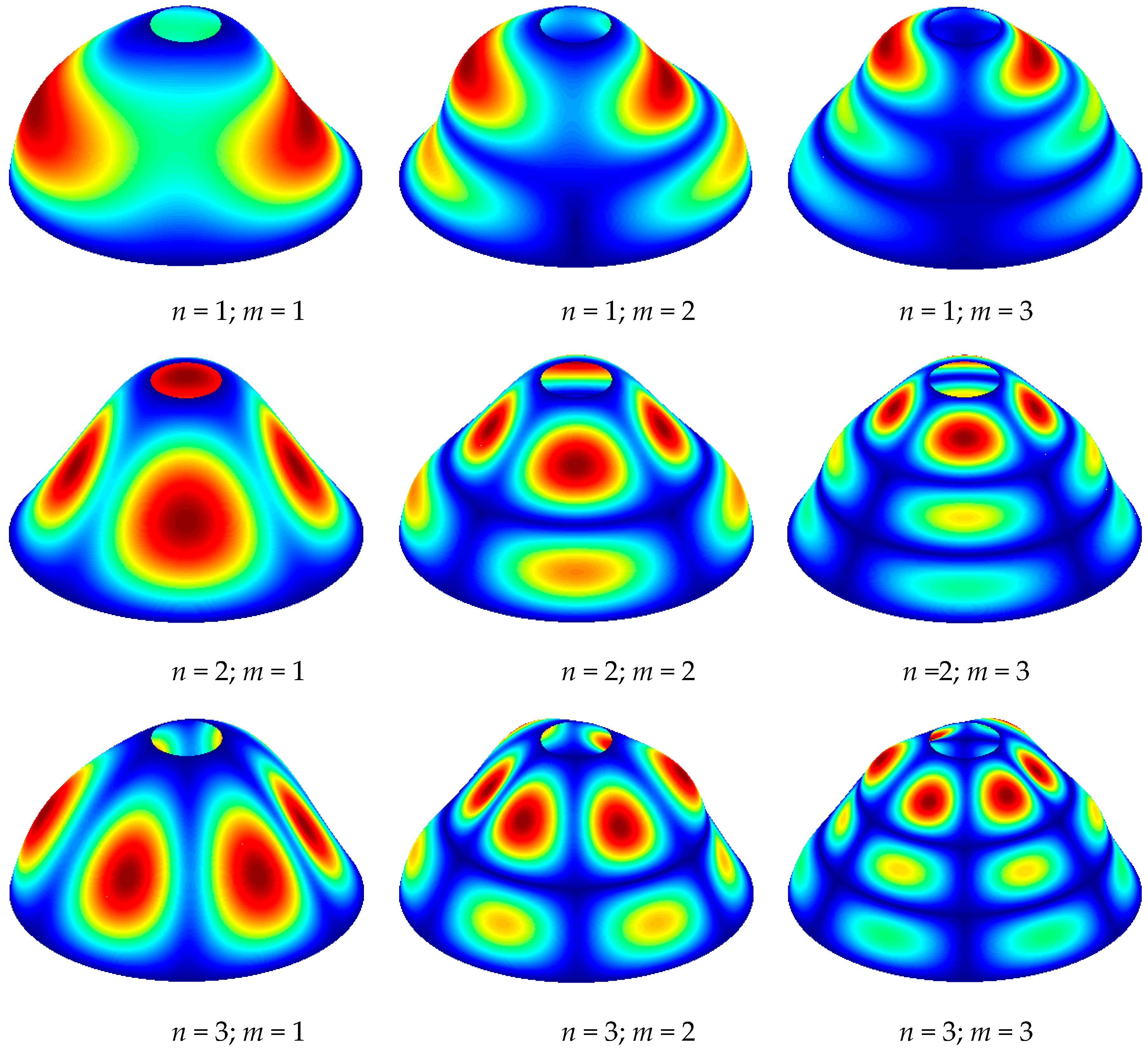
| n | m | Proposed Method | FEM |
|---|---|---|---|
| 0 | 1 | 1.2139 | 1.2144 |
| 2 | 1.3579 | 1.3586 | |
| 3 | 1.5621 | 1.5645 | |
| 4 | 1.6154 | 1.6183 | |
| 1 | 1 | 0.9499 | 0.9504 |
| 2 | 1.2605 | 1.2615 | |
| 3 | 1.6030 | 1.6070 | |
| 4 | 1.9770 | 1.9725 | |
| 2 | 1 | 0.7521 | 0.7524 |
| 2 | 1.1907 | 1.1924 | |
| 3 | 1.6002 | 1.6056 | |
| 4 | 2.1071 | 2.1083 | |
| 3 | 1 | 0.7171 | 0.7176 |
| 2 | 1.1811 | 1.1835 | |
| 3 | 1.6590 | 1.6566 | |
| 4 | 2.2217 | 2.2251 |
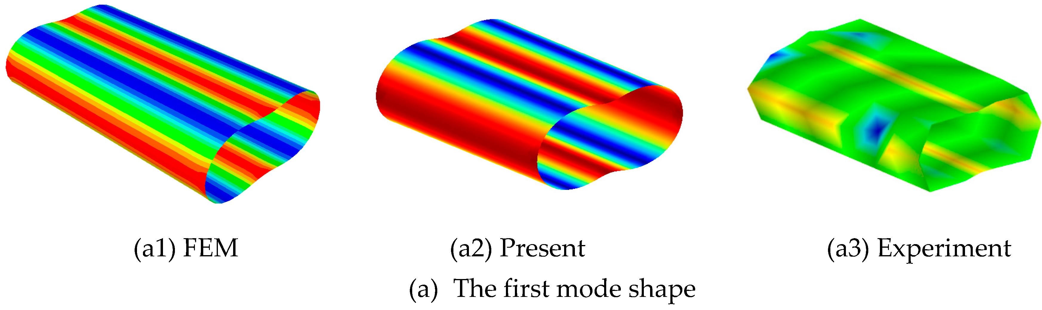
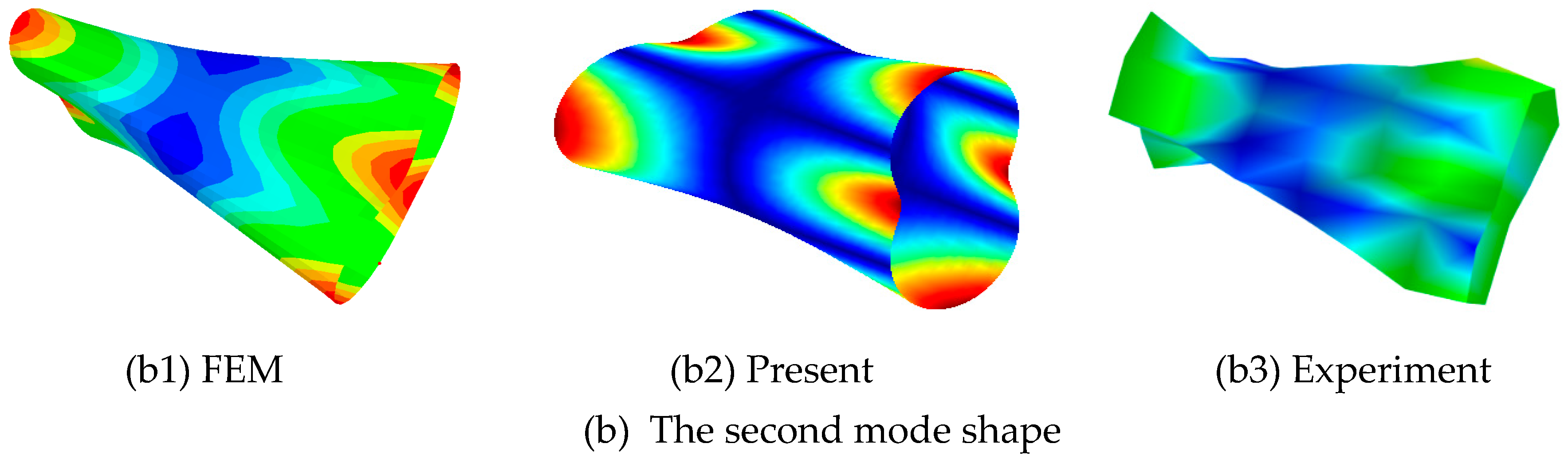
| n, m | Present | Experimental | Error (%) | FEM | Error (%) |
|---|---|---|---|---|---|
| 0, 1 | 545.89 | 551.97 | 1.11 | 547.49 | 0.29 |
| 2, 2 | 582.13 | 588.39 | 1.08 | 581.98 | 0.03 |
| 0, 3 | 1561.93 | 1572.53 | 0.68 | 1567.90 | 0.38 |
| 2, 3 | 1618.37 | 1656.42 | 2.35 | 1613.70 | 0.29 |
| 3, 3 | 2143.98 | 2169.05 | 1.17 | 2150.70 | 0.31 |
| Type | n | m | Boundary Restraints | |||||||||
|---|---|---|---|---|---|---|---|---|---|---|---|---|
| F–C | C–C | SD–SD | SS–SS | E1–E1 | E2–E2 | E3–E3 | F–E1 | F–E2 | F–SS | |||
| FGMI (a = 1; b = −0.5; c = 2; p = 2) | 1 | 1 | 0.7470 | 0.9238 | 0.6151 | 0.8886 | 0.6736 | 0.5307 | 0.2076 | 0.2171 | 0.4519 | 0.7301 |
| 2 | 1.1767 | 1.2318 | 0.8874 | 1.1522 | 0.9171 | 1.2104 | 0.5468 | 0.8334 | 1.1066 | 1.0967 | ||
| 3 | 1.4199 | 1.5746 | 1.1503 | 1.4582 | 1.2343 | 1.4709 | 1.1710 | 1.1866 | 1.4113 | 1.3661 | ||
| 4 | 1.6262 | 1.9378 | 1.4683 | 1.8208 | 1.5746 | 1.7016 | 1.4638 | 1.4535 | 1.4271 | 1.6000 | ||
| 5 | 1.7717 | 2.0975 | 1.8376 | 2.0156 | 2.0259 | 1.9062 | 1.5645 | 1.7696 | 1.7209 | 1.6947 | ||
| 2 | 1 | 0.5453 | 0.7334 | 0.6855 | 0.6973 | 0.7196 | 0.6154 | 0.5819 | 0.4742 | 0.4983 | 0.5329 | |
| 2 | 0.9432 | 1.1666 | 1.0460 | 1.0800 | 1.1426 | 1.1078 | 0.9250 | 0.9212 | 0.8446 | 0.8894 | ||
| 3 | 1.3195 | 1.5767 | 1.3190 | 1.4539 | 1.3368 | 1.5389 | 1.3106 | 1.3023 | 1.3013 | 1.2305 | ||
| 4 | 1.7651 | 2.0848 | 1.4434 | 1.9063 | 1.5690 | 2.0412 | 1.4790 | 1.3588 | 1.7237 | 1.6529 | ||
| 5 | 2.2154 | 2.5207 | 1.8933 | 2.4718 | 2.0823 | 2.2287 | 1.9788 | 1.7737 | 2.1426 | 2.1436 | ||
| 3 | 1 | 0.6918 | 0.7037 | 0.6469 | 0.6597 | 0.6939 | 0.6630 | 0.6588 | 0.6816 | 0.6549 | 0.6516 | |
| 2 | 1.1043 | 1.1629 | 1.0674 | 1.0763 | 1.1594 | 1.1255 | 1.0998 | 1.1029 | 1.0725 | 1.0362 | ||
| 3 | 1.4964 | 1.6405 | 1.5063 | 1.5173 | 1.6362 | 1.6151 | 1.5855 | 1.4963 | 1.4798 | 1.4098 | ||
| 4 | 1.9638 | 2.2032 | 1.9827 | 2.0370 | 2.0021 | 2.1782 | 1.8904 | 1.9536 | 1.9463 | 1.8532 | ||
| 5 | 2.5376 | 2.8897 | 2.0261 | 2.6731 | 2.1986 | 2.8331 | 2.1627 | 2.0105 | 2.5267 | 2.4127 | ||
| FGMII (a = 1; b = −0.5; c = 2; p = 2) | 1 | 1 | 0.7418 | 0.9171 | 0.6086 | 0.8875 | 0.6689 | 0.5274 | 0.2064 | 0.2161 | 0.4491 | 0.7153 |
| 2 | 1.1663 | 1.2205 | 0.8821 | 1.1388 | 0.9110 | 1.1991 | 0.5427 | 0.8263 | 1.0974 | 1.1007 | ||
| 3 | 1.4059 | 1.5589 | 1.1408 | 1.4569 | 1.2232 | 1.4590 | 1.1604 | 1.1759 | 1.4010 | 1.3328 | ||
| 4 | 1.6117 | 1.9209 | 1.4556 | 1.7561 | 1.5588 | 1.6896 | 1.4532 | 1.4381 | 1.4141 | 1.6112 | ||
| 5 | 1.7523 | 2.0820 | 1.8189 | 2.0554 | 2.0045 | 1.8919 | 1.5520 | 1.7494 | 1.7022 | 1.6794 | ||
| 2 | 1 | 0.5378 | 0.7271 | 0.6821 | 0.6895 | 0.7136 | 0.6103 | 0.5768 | 0.4670 | 0.4920 | 0.5171 | |
| 2 | 0.9331 | 1.1553 | 1.0399 | 1.0802 | 1.1315 | 1.0968 | 0.9159 | 0.9117 | 0.8351 | 0.8909 | ||
| 3 | 1.3062 | 1.5593 | 1.3101 | 1.4468 | 1.3285 | 1.5218 | 1.3017 | 1.2916 | 1.2878 | 1.2172 | ||
| 4 | 1.7468 | 2.0615 | 1.4329 | 1.8881 | 1.5518 | 2.0196 | 1.4630 | 1.3468 | 1.7066 | 1.6445 | ||
| 5 | 2.1931 | 2.5059 | 1.8788 | 2.4820 | 2.0593 | 2.2170 | 1.9600 | 1.7554 | 2.1281 | 2.0916 | ||
| 3 | 1 | 0.6846 | 0.6968 | 0.6436 | 0.6477 | 0.6872 | 0.6566 | 0.6524 | 0.6746 | 0.6482 | 0.6389 | |
| 2 | 1.0906 | 1.1506 | 1.0609 | 1.0731 | 1.1471 | 1.1136 | 1.0877 | 1.0892 | 1.0592 | 1.0300 | ||
| 3 | 1.4762 | 1.6214 | 1.4944 | 1.5073 | 1.6171 | 1.5961 | 1.5665 | 1.4761 | 1.4597 | 1.3933 | ||
| 4 | 1.9404 | 2.1772 | 1.9727 | 2.0216 | 1.9913 | 2.1526 | 1.8796 | 1.9316 | 1.9231 | 1.8339 | ||
| 5 | 2.5057 | 2.8601 | 2.0097 | 2.6553 | 2.1728 | 2.8113 | 2.1386 | 1.9983 | 2.4952 | 2.3801 | ||
| Power-Law Exponents | n | m | C–C | SD–SD | F–SS |
|---|---|---|---|---|---|
| p = 0.2 | 1 | 1 | 0.9480 | 0.6315 | 0.7461 |
| 2 | 1.2583 | 0.9133 | 1.1301 | ||
| 3 | 1.6007 | 1.1769 | 1.3859 | ||
| 2 | 1 | 0.7507 | 0.7047 | 0.5374 | |
| 2 | 1.1888 | 1.0703 | 0.9119 | ||
| 3 | 1.5983 | 1.3557 | 1.2499 | ||
| 3 | 1 | 0.7161 | 0.6612 | 0.6606 | |
| 2 | 1.1796 | 1.0868 | 1.0534 | ||
| 3 | 1.6574 | 1.5264 | 1.4231 | ||
| p = 0.5 | 1 | 1 | 0.9451 | 0.6297 | 0.7444 |
| 2 | 1.2550 | 0.9104 | 1.1259 | ||
| 3 | 1.5971 | 1.1737 | 1.3836 | ||
| 2 | 1 | 0.7486 | 0.7025 | 0.5369 | |
| 2 | 1.1859 | 1.0673 | 0.9090 | ||
| 3 | 1.5951 | 1.3514 | 1.2472 | ||
| 3 | 1 | 0.7144 | 0.6593 | 0.6595 | |
| 2 | 1.1772 | 1.0841 | 1.0508 | ||
| 3 | 1.6545 | 1.5232 | 1.4207 | ||
| p = 2 | 1 | 1 | 0.9321 | 0.6210 | 0.7359 |
| 2 | 1.2395 | 0.8969 | 1.1078 | ||
| 3 | 1.5796 | 1.1585 | 1.3711 | ||
| 2 | 1 | 0.7389 | 0.6922 | 0.5332 | |
| 2 | 1.1721 | 1.0532 | 0.8959 | ||
| 3 | 1.5789 | 1.3322 | 1.2339 | ||
| 3 | 1 | 0.7064 | 0.6508 | 0.6534 | |
| 2 | 1.1650 | 1.0712 | 1.0389 | ||
| 3 | 1.6394 | 1.5074 | 1.4081 | ||
| p = 5 | 1 | 1 | 0.9164 | 0.6103 | 0.7236 |
| 2 | 1.2221 | 0.8807 | 1.0892 | ||
| 3 | 1.5625 | 1.1413 | 1.3542 | ||
| 2 | 1 | 0.7276 | 0.6803 | 0.5280 | |
| 2 | 1.1575 | 1.0383 | 0.8832 | ||
| 3 | 1.5646 | 1.3084 | 1.2210 | ||
| 3 | 1 | 0.6983 | 0.6422 | 0.6460 | |
| 2 | 1.1540 | 1.0597 | 1.0285 | ||
| 3 | 1.6282 | 1.4954 | 1.3991 |
| h1:h2:h3:h4:h5 | n | m | C–C | SD–SD | F–SS |
|---|---|---|---|---|---|
| 0.04:0.05:0.06:0.07:0.08 | 1 | 1 | 0.9579 | 0.5884 | 0.7655 |
| 2 | 1.3085 | 0.9008 | 1.1470 | ||
| 3 | 1.6903 | 1.2140 | 1.4461 | ||
| 2 | 1 | 0.7667 | 0.6952 | 0.5476 | |
| 2 | 1.2454 | 1.1009 | 0.9267 | ||
| 3 | 1.7064 | 1.2969 | 1.3145 | ||
| 3 | 1 | 0.7590 | 0.6841 | 0.6925 | |
| 2 | 1.2600 | 1.1513 | 1.1067 | ||
| 3 | 1.7917 | 1.6410 | 1.5140 | ||
| 0.08:0.07:0.06:0.05:0.04 | 1 | 1 | 0.8600 | 0.6915 | 0.6176 |
| 2 | 1.1979 | 0.9477 | 1.0841 | ||
| 3 | 1.6283 | 1.1045 | 1.2400 | ||
| 2 | 1 | 0.7026 | 0.6680 | 0.5916 | |
| 2 | 1.1782 | 1.0529 | 0.9674 | ||
| 3 | 1.6697 | 1.4977 | 1.3075 | ||
| 3 | 1 | 0.6992 | 0.6584 | 0.6578 | |
| 2 | 1.2297 | 1.1176 | 1.1192 | ||
| 3 | 1.8009 | 1.6410 | 1.6103 | ||
| 0.04:0.06:0.08:0.07:0.05 | 1 | 1 | 0.8483 | 0.5982 | 0.6988 |
| 2 | 1.2766 | 0.8162 | 1.1448 | ||
| 3 | 1.6965 | 1.1861 | 1.3817 | ||
| 2 | 1 | 0.6747 | 0.6343 | 0.5059 | |
| 2 | 1.2266 | 1.0603 | 0.9036 | ||
| 3 | 1.7104 | 1.4039 | 1.2943 | ||
| 3 | 1 | 0.6993 | 0.6493 | 0.6457 | |
| 2 | 1.2530 | 1.1403 | 1.1109 | ||
| 3 | 1.8046 | 1.6523 | 1.5196 | ||
| 0.07:0.05:0.04:0.06:0.08 | 1 | 1 | 1.0086 | 0.6664 | 0.7052 |
| 2 | 1.2356 | 0.9912 | 1.0789 | ||
| 3 | 1.6421 | 1.1382 | 1.4098 | ||
| 2 | 1 | 0.8278 | 0.7647 | 0.6457 | |
| 2 | 1.1948 | 1.0710 | 0.9595 | ||
| 3 | 1.6748 | 1.2893 | 1.3483 | ||
| 3 | 1 | 0.8000 | 0.7185 | 0.7324 | |
| 2 | 1.2351 | 1.1212 | 1.1102 | ||
| 3 | 1.7878 | 1.6336 | 1.5970 |
© 2018 by the authors. Licensee MDPI, Basel, Switzerland. This article is an open access article distributed under the terms and conditions of the Creative Commons Attribution (CC BY) license (http://creativecommons.org/licenses/by/4.0/).
Share and Cite
Pang, F.; Li, H.; Jing, F.; Du, Y. Application of First-Order Shear Deformation Theory on Vibration Analysis of Stepped Functionally Graded Paraboloidal Shell with General Edge Constraints. Materials 2019, 12, 69. https://doi.org/10.3390/ma12010069
Pang F, Li H, Jing F, Du Y. Application of First-Order Shear Deformation Theory on Vibration Analysis of Stepped Functionally Graded Paraboloidal Shell with General Edge Constraints. Materials. 2019; 12(1):69. https://doi.org/10.3390/ma12010069
Chicago/Turabian StylePang, Fuzhen, Haichao Li, Fengmei Jing, and Yuan Du. 2019. "Application of First-Order Shear Deformation Theory on Vibration Analysis of Stepped Functionally Graded Paraboloidal Shell with General Edge Constraints" Materials 12, no. 1: 69. https://doi.org/10.3390/ma12010069