
Inducing Stable α + β Microstructures during Selective Laser Melting of Ti-6Al-4V Using Intensified Intrinsic Heat Treatments


Abstract
:1. Introduction
2. Materials and Methods
2.1. Selective Laser Melting Process
2.2. Characterization of the Ti-6Al-4V Alloy
2.2.1. Microscopy
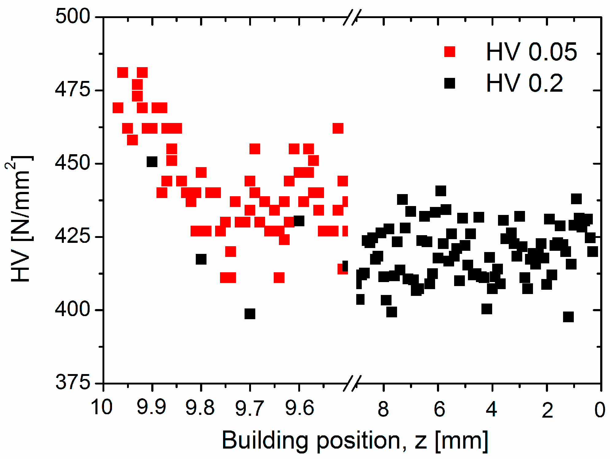
2.2.2. Hardness
2.2.3. High Energy Synchrotron X-ray Diffraction
2.2.4. Synchrotron Holographic X-ray Computed Tomography
3. Results
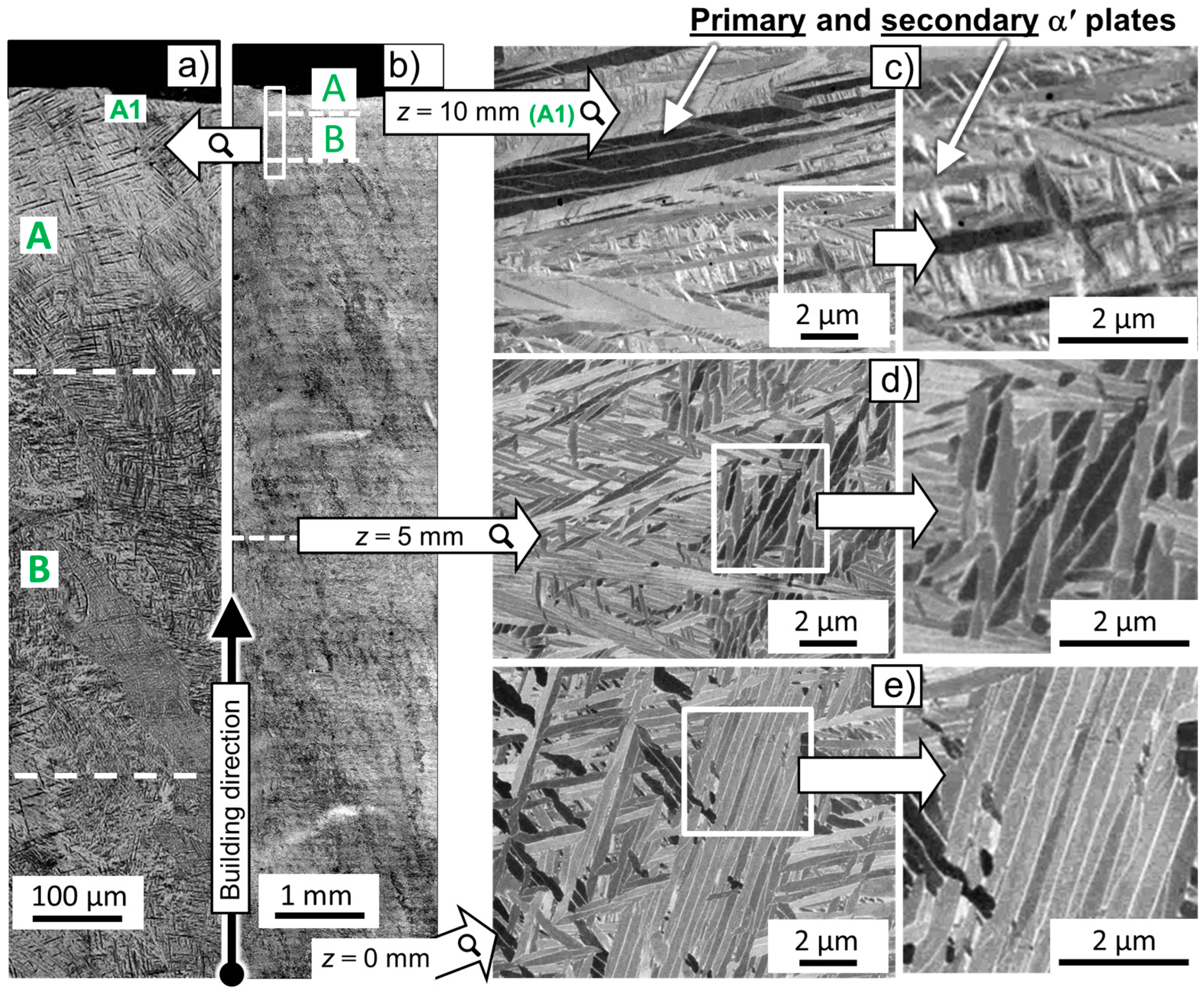
3.1. Microstructural Evolution along the SLM Building Direction
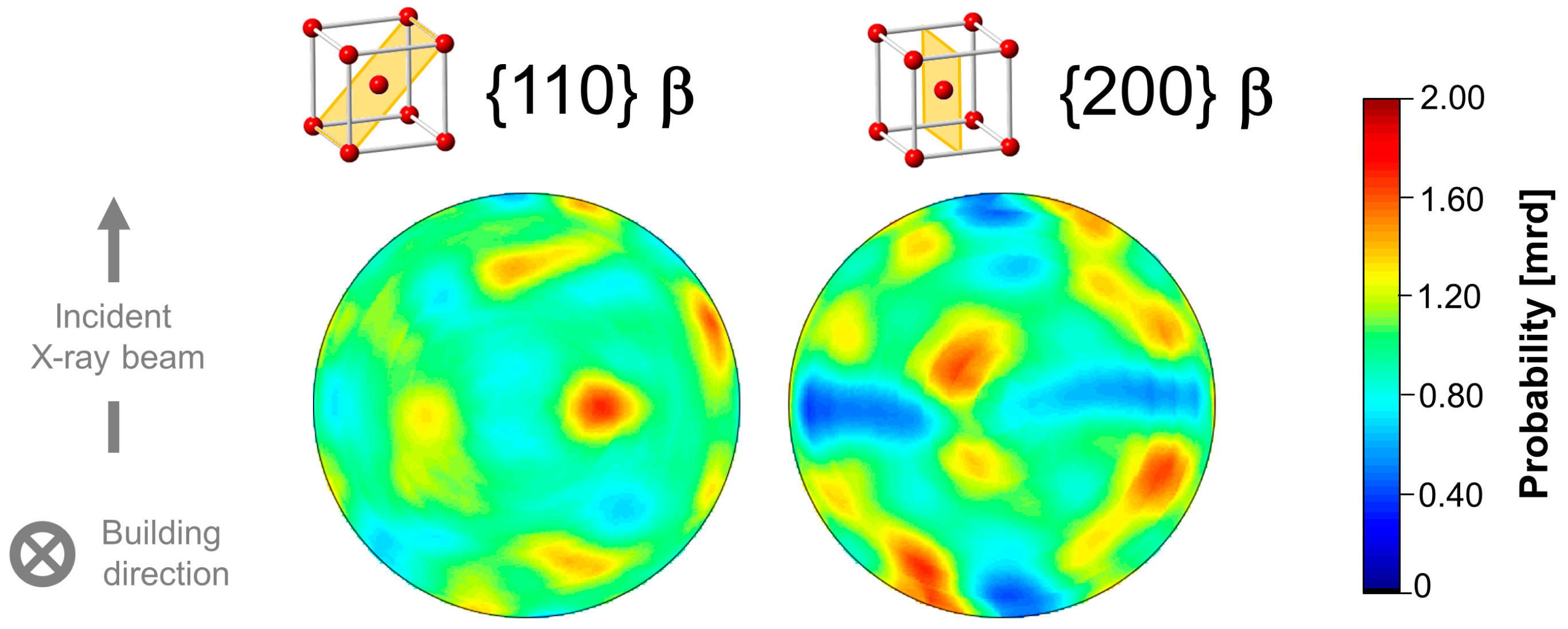
3.2. Texture and 3D Architecture of β
4. Discussion
4.1. Effect of the Intrinsic Heat Treatment: Microstructural Evolution along the Building Direction
4.1.1. Formation of β
4.1.2. Formation of α
4.1.3. Formation of α2-Ti3Al
4.2. Diffusion-Driven Microstructural Stabilization along the Building Direction
5. Conclusions
- The intensified intrinsic heat treatment applied during SLM provokes extensive martensite decomposition (α’ → α + β) along the building direction. This results in the formation of a uniform, fine lamellar α + β microstructure.
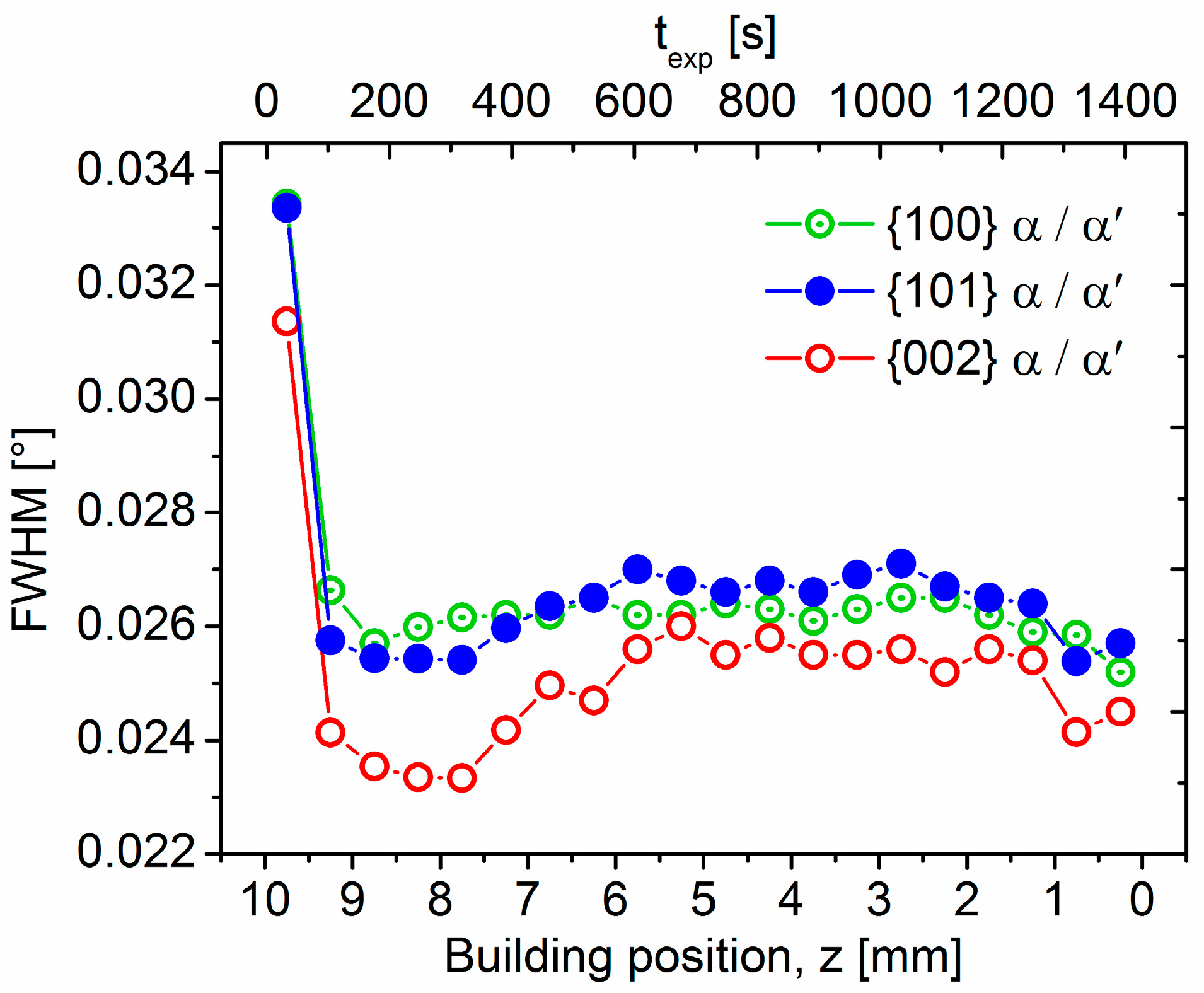
- A relatively thin martensitic layer (~150–250 µm) forms for the lastly synthesized layers of material as a consequence of the IHT influence at T > Ms. The transition from α’ plates to stable α lamellae is reflected along the building direction by an abrupt decrease of the full width at half maximum of hcp reflections as well as by the microhardness evolution.
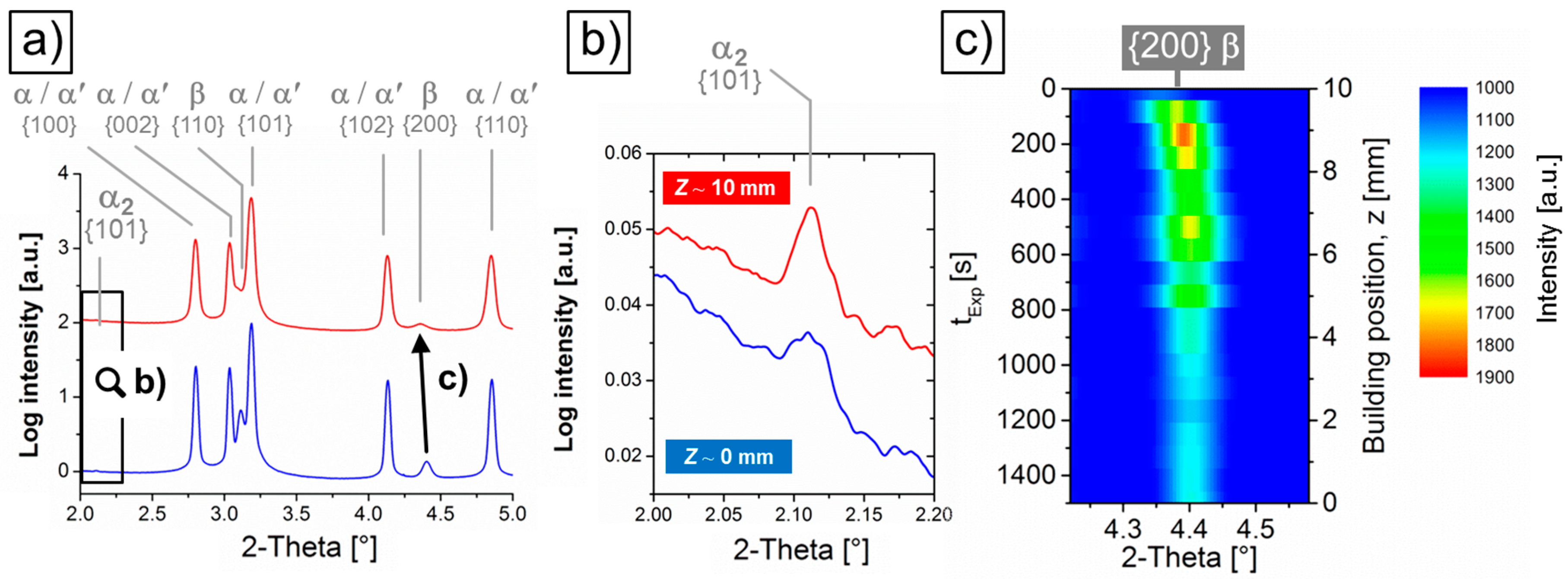
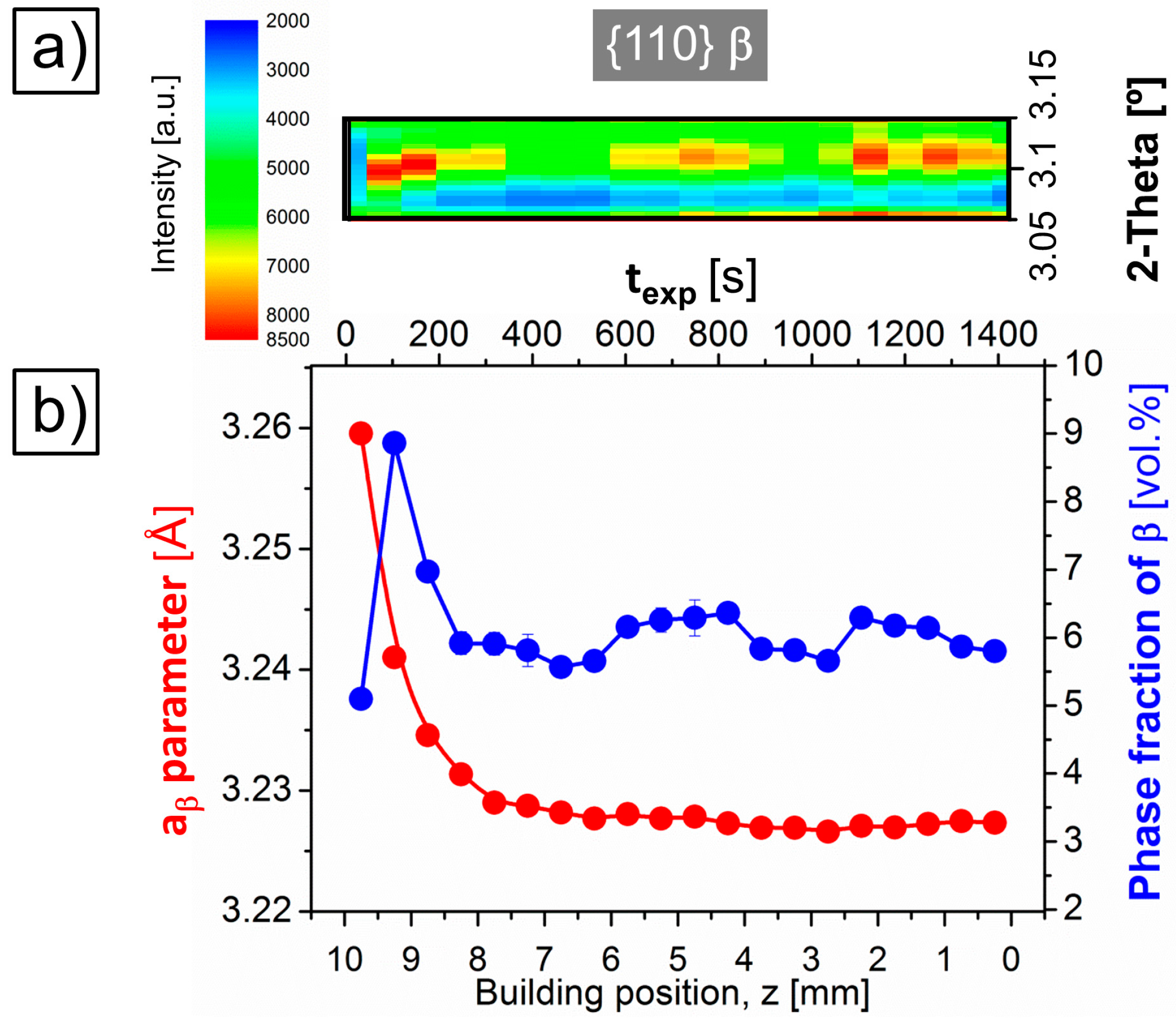
- The evolution of the lattice parameter of β, aβ, indicates a gradual variation in the IHT-induced element partitioning between β and α’/α along the building direction of the sample. Decreasing aβ values are presumably associated with a progressive partitioning of V to β. The results obtained establish aβ as an indicator for the microstructural degree of stabilization of the SLM Ti-6Al-4V alloy.
- Columnar prior β grains form in an inclined manner with respect to the building direction. This may occur due to uneven heat dissipation caused by the chosen scanning strategy and can be correlated with the weak texture obtained for the SLM Ti-6Al-4V alloy.
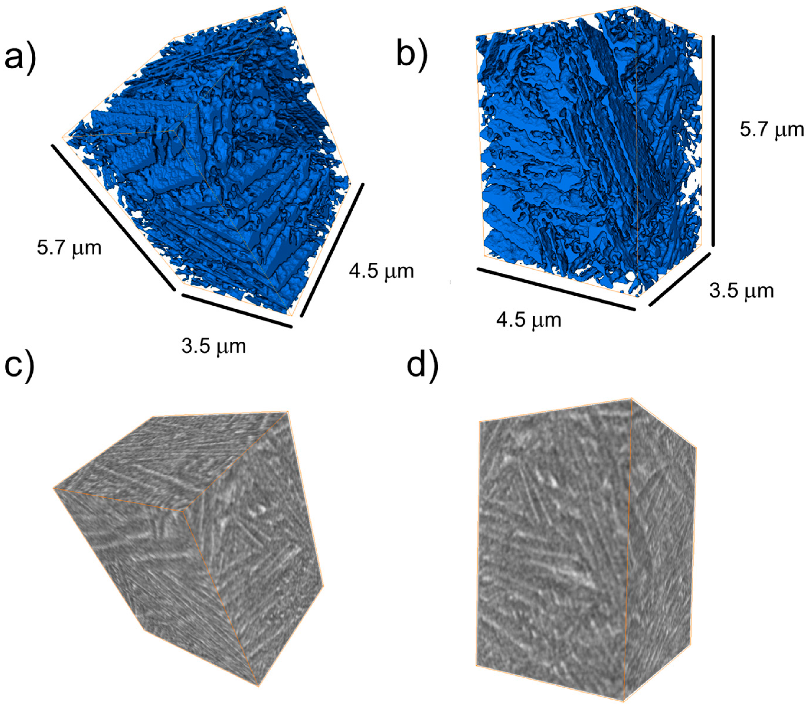
- In regions highly affected by the IHT, interconnected β layers form as a 3D network percolating through colonies of α lamellae, as revealed by high-resolution synchrotron holographic X-ray computed tomography. Consequently, homogeneous distributions of slip transfer between phases across the incoherent α/β interphase may be obtained.
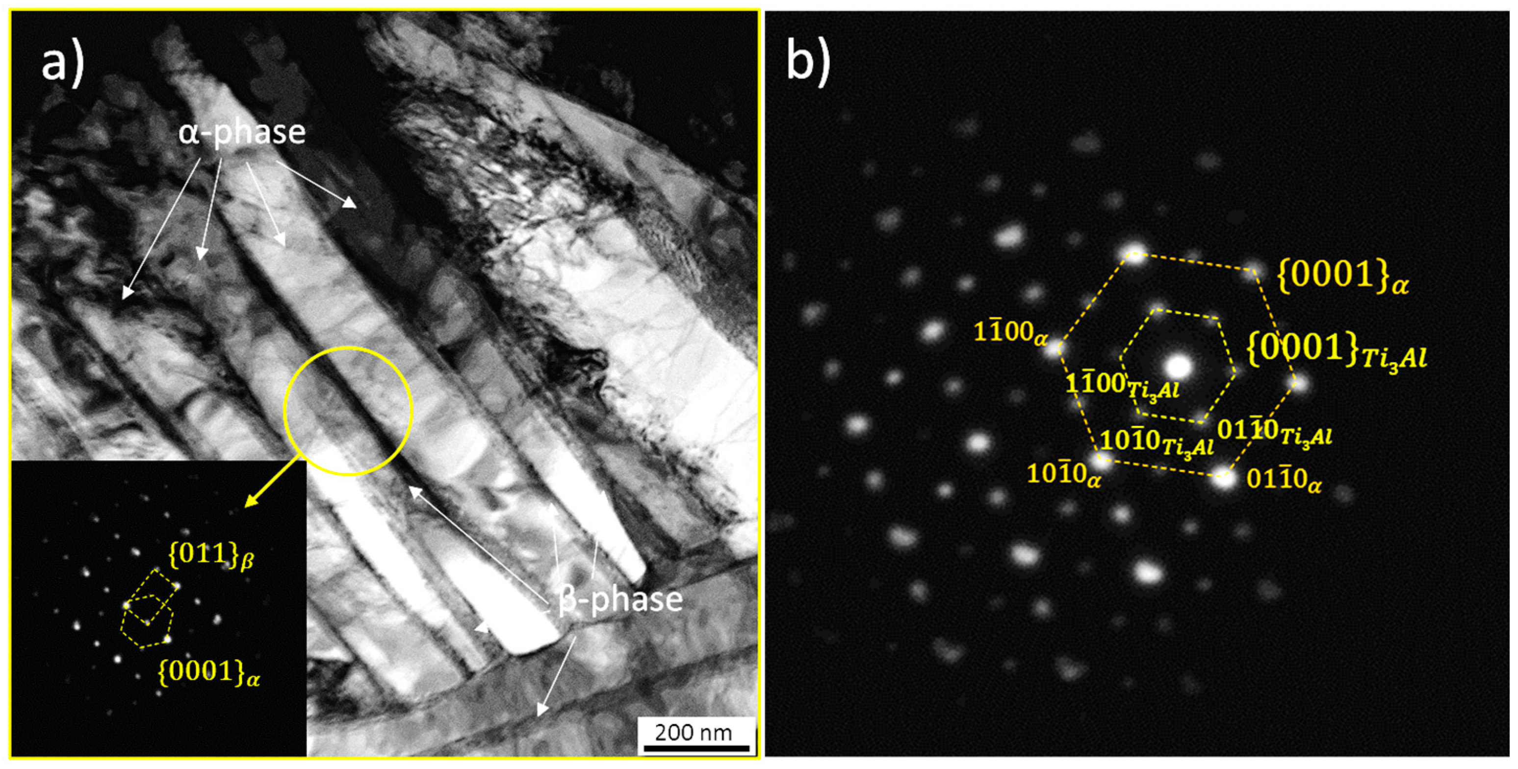
- Structural evidence of the formation of the intermetallic α2-Ti3Al phase is revealed by high-energy synchrotron X-ray diffraction along the building direction of the sample as well as by TEM performed at a central region of the samples.
Acknowledgments
Author Contributions
Conflicts of Interest
References
- Froes, F.H.; Dutta, B. The additive manufacturing (AM) of titanium alloys. Adv. Mater. Res. 2014, 1019, 19–25. [Google Scholar]
- Yap, C.Y.; Chua, C.K.; Dong, Z.L.; Liu, Z.H.; Zhang, D.Q.; Loh, L.E.; Sing, S.L. Review of selective laser melting: Materials and applications. Appl. Phys. Rev. 2015, 2, 041101-1–041101-21. [Google Scholar] [CrossRef]
- Herbert, R.J. Viewpoint: Metallurgical aspects of powder bed metal additive manufacturing. J. Mater. Sci. 2016, 51, 1165–1175. [Google Scholar] [CrossRef]
- Kobryn, P.A.; Semiatin, S.L. The laser additive manufacture of Ti-6Al-4V. JOM 2001, 53, 40–42. [Google Scholar] [CrossRef]
- Das, M.; Balla, V.K.; Basu, D.; Bose, S.; Bandyopadhyay, A. Laser processing of SiC-particle-reinforced coating on titanium. Scr. Mater. 2010, 63, 438–441. [Google Scholar] [CrossRef]
- Vilaro, T.; Colin, C.; Bartout, J.D. As-fabricated and heat-Treated microstructures of the Ti-6Al-4V alloy processed by selective laser melting. Metal. Mater. Trans. A 2011, 42, 3190–3199. [Google Scholar] [CrossRef]
- Hodge, N.E.; Ferencz, R.M.; Solberg, J.M. Implementation of a thermomechanical model for the simulation of selective laser melting. Comput. Mech. 2014, 54, 33–51. [Google Scholar] [CrossRef]
- Barriobero-Vila, P. Phase Transformation Kinetics during Continuous Heating of α + β and Metastable β Titanium Alloys. Ph.D. Thesis, Vienna University of Technology, Vienna, Austria, 2015. Available online: https://www.researchgate.net/publication/282353993_Phase_transformation_kinetics_during_continuous_heating_of_ab_and_metastable_b_titanium_alloys (accessed on 30 January 2017). [Google Scholar]
- Leyens, C.; Peters, M. Titanium and Titanium Alloys, 1st ed.; Wiley-VCH: Weinheim, Germany, 2003. [Google Scholar]
- Xu, W.; Brandt, S.; Sun, S.; Elambasseril, J.; Liu, Q.; Latham, K.; Xia, K.; Qian, M. Additive manufacturing of strong and ductile Ti-6Al-4V by selective laser melting via in situ martensite decomposition. Acta Mater. 2015, 85, 74–84. [Google Scholar] [CrossRef]
- Simonelli, M.; Tse, Y.Y.; Tuck, C. The formation of α + β microstructure in as-fabricated selective laser melting of Ti-6Al-4V. J. Mater. Res. 2014, 29, 2028–2035. [Google Scholar] [CrossRef]
- Kasperovich, G.; Haubrich, J.; Gussone, J.; Requena, G. Correlation between porosity and processing parameters in TiAl6V4 produced by selective laser melting. Mater. Des. 2016, 105, 160–170. [Google Scholar] [CrossRef]
- Vracken, B.; Buls, S.; Kruth, J.-P.; Van Humbeeck, J. Preheating of selective laser melting Ti6Al4V: microstructure and mechanical properties. In Proceedings of the 13th Wold Conference on Titanium, 1st ed.; Additive and near Net Shape Manufacturing; John Wiley & Sons: Haboken, NJ, USA, 2016; pp. 1273–1277. [Google Scholar]
- Thijs, L.; Verhaeghe, F.; Craeghs, Y.; Van Humbeeck, J.; Kruth, J.-P. A study of the microstructural evolution during selective laser melting of Ti-6Al-4V. Acta Mater. 2010, 58, 3303–3312. [Google Scholar] [CrossRef]
- Gong, H.G.; Rafi, K.; Hengfeng, G.; Starr, T.; Stucker, B. Analysis of defect generation in Ti-6Al-4V parts made using powder bed fusion additive manufacturing processes. Addit. Manuf. 2014, 1–4, 87–98. [Google Scholar] [CrossRef]
- Schell, N.; King, A.; Beckmann, F.; Fischer, T.; Müller, M.; Schreyer, A. The high energy materials Beamline (HEMS) at PETRA III. Mater. Sci. Forum 2014, 772, 57–61. [Google Scholar] [CrossRef]
- Hammersley, A.; Svensson, S.O.; Thompson, A. Calibration and correction of spatial distortions in 2D detector systems. Nucl. Instrum. Methods Phys. Res. A 1994, 346, 312–321. [Google Scholar] [CrossRef]
- Lutterotti, L.; Matthies, S.; Wenk, H.R.; Schultz, A.J.; Richardson, J. Combined texture and structure analysis of deformed limestone from time-of-flight neutron diffraction spectra. J. Appl. Phys. 1997, 81, 594–600. [Google Scholar] [CrossRef]
- TOPAS, version 6.0; Bruker AXS: Karlsruhe, Germany, 2015.
- Mokso, R.; Cloetens, P.; Maire, E.; Ludwig, W.; Buffière, J.-Y. Nanoscale zoom tomography with hard X-rays using Kirkpatrick-Baez optics. Appl. Phys. Lett. 2007, 90, 144104. [Google Scholar] [CrossRef]
- Cloetens, P.; Ludwig, W.; Baruchel, J.; Van Dyck, D.; Van Landuyt, J.; Guigay, J.P.; Schlenker, M. Holotomography: Quantitative phase tomography with micrometer resolution using hard synchrotron radiation X-rays. Appl. Phys. Lett. 1999, 75, 2912–2914. [Google Scholar] [CrossRef]
- ID16A—Nano-Imaging Beamline. Available online: http://www.esrf.fr/UsersAndScience/Experiments/Imaging/ID16A (accessed on 30 January 2017).
- Requena, G.; Cloetens, P.; Altendorfer, W.; Poletti, C.; Tolnai, D.; Warchomicka, F.; Degischer, H.P. Sub-micrometer synchrotron tomography of multiphase metals using Kirkpatrick-Baez optics. Scr. Mater. 2009, 61, 760–763. [Google Scholar] [CrossRef]
- Bracewell, R.N.; Riddle, A.C. Inversion of fan-beam scans in radio astronomy. Astron. J. 1967, 150, 427–434. [Google Scholar] [CrossRef]
- Yang, J.; Han, J.; Yu, J.; Yin, J.; Gao, M.; Wang, Z.; Zeng, X. Role of molten pool mode on formability, microstructure and mechanical properties of selective laser melted Ti-6Al-4V alloy. Mater. Des. 2016, 110, 558–570. [Google Scholar] [CrossRef]
- Simonelli, M.; Tse, Y.Y.; Tuck, C. On the Texture Formation of Selective Laser Melted Ti-6Al-4V. Metall. Mater. Trans. A 2014, 45, 2863–2872. [Google Scholar] [CrossRef]
- Vrancken, B.; Thijs, L.; Kruth, J.-P.; Van Humbeeck, J. Heat treatment of Ti6Al4V produced by selective laser melting: Microstructure and mechanical properties. J. Alloy Compd. 2012, 541, 177–185. [Google Scholar] [CrossRef]
- Xu, W.; Lui, E.W.; Pateras, A.; Qian, M.; Brandt, M. In situ tailoring microstructure in additively manufactured Ti-6Al-4V for superior mechanical performance. Acta Mater. 2017, 125, 390–400. [Google Scholar] [CrossRef]
- Lütjering, G.; Williams, J.C. Titanium, 2nd ed.; Springer: Berlin, Germany, 2007. [Google Scholar]
- Banerjee, S.; Mukhopadhyay, P. Phase Transformations: Examples from Titanium and Zirconium Alloys, 1st ed.; Elsevier: Oxford, UK, 2007. [Google Scholar]
- Barriobero-Vila, P.; Requena, G.; Schwarz, S.; Warchomicka, F.; Buslaps, T. Influence of phase transformation kinetics on the formation of α in a β-quenched Ti-5Al-5Mo-5V-3Cr-1Zr alloy. Acta Mater. 2015, 95, 90–101. [Google Scholar] [CrossRef]
- Yang, J.; Yu, H.; Yin, J.; Gao, M.; Wang, Z.; Zeng, X. Formation and control of martensite in Ti-6Al-4V alloy produced by selective laser melting. Mater. Des. 2016, 108, 308–318. [Google Scholar] [CrossRef]
- Mittemeijer, E.J.; Scardi, P. Diffraction Analysis of the Microstructure of Materials, 1st ed.; Springer: Berlin, Germany, 2004. [Google Scholar]
- Malinov, S.; Sha, W.; Guo, Z.; Tang, C.C.; Long, A.E. Synchrotron X-ray diffraction study of the phase transformations in titanium alloys. Mater. Charact. 2002, 48, 279–295. [Google Scholar] [CrossRef] [Green Version]
- Fu, C.H.; Guo, Y.B. Three-dimensional temperature gradient mechanism in selective laser melting of Ti-6Al-4V. J. Manuf. Sci. Eng. 2014, 136, 061004. [Google Scholar] [CrossRef]
- Verhaeghe, F.; Craeghs, T.; Heulens, J.; Pandelaers, L. A pragmatic model for selective laser melting with evaporation. Acta Mater. 2009, 57, 6006–6012. [Google Scholar] [CrossRef]
- Xu, W.; Sun, S.; Elambasseril, J.; Liu, Q.; Brandt, M.; Quian, M. Ti-6Al-4V additively Manufactured by selective laser melting with superior mechanical properties. JOM 2015, 67, 668–673. [Google Scholar] [CrossRef]
- Welsch, G.; Bunk, W. Deformation modes of the α-phase of Ti-6Al-4V as a function of oxygen concentration and aging temperature. Metall. Trans. A 1982, 13, 889–899. [Google Scholar] [CrossRef]
- Boyer, R.; Welsch, G.; Collings, E.W. Material Properties Handbook: Titanium Alloys, 4th ed.; ASM International: Novelty, OH, USA, 1994. [Google Scholar]
- Tarzimoghadam, Z.; Sandlöbes, S.; Pradeep, K.G.; Raabe, D. Microstructure design and mechanical properties in near-α Ti-4Mo alloy. Acta Mater. 2015, 97, 291–304. [Google Scholar] [CrossRef]
- Banerjee, S.; Vijayakar, S.J.; Krishnan, R. Precipitation in zirconium-niobium martensites. J. Nucl. Mater. 1976, 62, 229–239. [Google Scholar] [CrossRef]
- Barriobero-Vila, P.; Requena, G.; Buslaps, T.; Alfeld, M.; Boesenberg, U. Role of element partitioning on the α – β phase transformation kinetics of a bi-modal Ti-6Al-6V-2Sn alloy during continuous heating. J. Alloy Compd. 2015, 626, 330–339. [Google Scholar] [CrossRef]


| P | v | h | F | x | Ev * | ||
|---|---|---|---|---|---|---|---|
| Laser power (W) | Scanning velocity (mm/s) | Hatch distance (µm) | Focal offset distance (mm) | Layer thickness (µm) | Volume energy density (J/mm3) | Strategy of laser pattern | Building platform temperature (°C) |
| 175 | 600 | 40 | 2.0 | 30 | 243 | Zig-zag scanning | 200 |
| Energy (keV) | Wavelength (Å) | Slit-Aperture Size (mm2) | Sample-Detector Distance (mm) | Acquisition Time (s) | Read-out Time (s) | Detector |
|---|---|---|---|---|---|---|
| 100 | 0.124 | 0.5 × 0.5 | 1601.2 | 3 | 2 | Perkin Elmer XRD 1621 |
© 2017 by the authors. Licensee MDPI, Basel, Switzerland. This article is an open access article distributed under the terms and conditions of the Creative Commons Attribution (CC BY) license ( http://creativecommons.org/licenses/by/4.0/).
Share and Cite
Barriobero-Vila, P.; Gussone, J.; Haubrich, J.; Sandlöbes, S.; Da Silva, J.C.; Cloetens, P.; Schell, N.; Requena, G. Inducing Stable α + β Microstructures during Selective Laser Melting of Ti-6Al-4V Using Intensified Intrinsic Heat Treatments. Materials 2017, 10, 268. https://doi.org/10.3390/ma10030268
Barriobero-Vila P, Gussone J, Haubrich J, Sandlöbes S, Da Silva JC, Cloetens P, Schell N, Requena G. Inducing Stable α + β Microstructures during Selective Laser Melting of Ti-6Al-4V Using Intensified Intrinsic Heat Treatments. Materials. 2017; 10(3):268. https://doi.org/10.3390/ma10030268
Chicago/Turabian StyleBarriobero-Vila, Pere, Joachim Gussone, Jan Haubrich, Stefanie Sandlöbes, Julio Cesar Da Silva, Peter Cloetens, Norbert Schell, and Guillermo Requena. 2017. "Inducing Stable α + β Microstructures during Selective Laser Melting of Ti-6Al-4V Using Intensified Intrinsic Heat Treatments" Materials 10, no. 3: 268. https://doi.org/10.3390/ma10030268
APA StyleBarriobero-Vila, P., Gussone, J., Haubrich, J., Sandlöbes, S., Da Silva, J. C., Cloetens, P., Schell, N., & Requena, G. (2017). Inducing Stable α + β Microstructures during Selective Laser Melting of Ti-6Al-4V Using Intensified Intrinsic Heat Treatments. Materials, 10(3), 268. https://doi.org/10.3390/ma10030268