1. Introduction
The demand of electric energy has been continuously increased [
1], whereas its supply has been saturated due to geographical, social, and environmental problems, such as spatial limitation, objection of residents, and pollutions. As a solution for electrical energy balancing problem, distributed generations (DGs) and microgrids have been increasingly penetrated into power systems. On the other hand, renewable energy sources (RESs) have also been drastically increased in terms of a solution for environmental pollutions [
2]. Introduction of both a microgrid and a RES has launched many new projects, such as [
3,
4,
5], which attempt to interconnect RESs into isolated power systems (e.g., remote islands, deserts), thereby constructing a standalone microgrid with high RESs penetration level. Island areas, which are target sites for constructing standalone microgrids, are typically in a circumstance of abundant energy sources of wind (in case of seashores of islands) and/or solar irradiance (in case of deserts). However, standalone microgrids have low system inertia and this may cause large frequency deviation even for small load change. Moreover, increasing penetration level of RESs into standalone microgrids makes the frequency stability problem even worse.
In conventional power systems, frequency deviation is inevitable if load and/or output power of RESs are changed. Besides, the active power sharing is based on frequency deviations. Typically, in remote islands, the grid voltage is formed by diesel generators and hence the system frequency is directly related to the inertia generators. Since the inertia of a small isolated power system is low, large frequency deviations may be occurred by change of load conditions. On the other hand, in standalone microgrids with inverter-interfaced DGs, active power-frequency (P-f) droop control method has been used. Though this system has no mechanical inertia, P-f droop control method emulates the characteristics of synchronous generators, and hence the system frequency is deviated proportional to both a droop coefficient and the amount of load change. Consequently, the frequency deviation is inevitable in this case too.
The active power sharing methods in standalone microgrids can be categorized into two types—whether they use the droop control or not [
6]. Most of them adopt the frequency droop control which has been used in the conventional power system composed of large synchronous generators [
7,
8,
9,
10]. However, since standalone microgrids have low system inertia, the frequency is likely to be largely deviated from its nominal value. As opposed to the conventional method, Vandoorn et al. [
11] and Yu et al. [
12] proposed active and reactive power (PQ) sharing method based on voltage and frequency deviation, respectively. However, it is effective only in low voltage networks. Moreover, reactive power sharing is based on the frequency, thereby the frequency deviation cannot be prevented. In [
13], non-droop-based power sharing method using the communication infrastructure was proposed. However, the frequency deviation cannot be prevented if the load change occurs due to communication time delay. References Lopes et al. [
14] and Chuang et al. [
15] also proposed a centralized control method. However, they still adopted the frequency droop control method, thereby the frequency deviation is inevitable. The frequency variation during load condition change is one of the main reasons that the penetration level of RESs cannot be grown in standalone microgrids. However, the frequency deviation is necessary for active power sharing according to the conventional control method.
In this paper, the active power sharing method without the frequency deviation in a standalone microgrid with high RESs’ penetration level is proposed. To this end, a battery energy storage system (BESS) acts as constant frequency (CF) control mode, while the other DGs share active power based on a state of charge (SOC) deviation instead of the frequency deviation. The active power sharing methods are categorized as a primary and a secondary SOC control, which are to cope with transient load changes and the SOC deviations, respectively.
The rest of this paper is organized as follows.
Section 2 shows the details of SOC-based active power sharing method.
Section 3 describes the system configurations.
Section 4 shows the case studies and
Section 5 outlines the conclusion.
2. State of Charge-Based Active Power Sharing Method
In order to eliminate the frequency deviations under load condition variations, decoupling of active power and frequency and coupling of active power and SOC of a BESS are proposed in this paper. To this end, a BESS must be connected to a standalone microgrid and be operated in a CF control mode whereas the other DGs must be controlled as a PQ control mode.
2.1. Relationships between Active Power and State of Charge of a Battery Energy Storage System
The key idea of this paper is to relate the whole load variation in a standalone microgrid to the SOC of a BESS. To this end, only a single BESS whose SOC is determined to be related the load variation should be operated in a CF control mode. The output frequency of the BESS is determined by the inverter and hence it can change the output voltage angle instantaneously unlike synchronous generators. In this way, during the load variation of the system, the frequency can be maintained at the desired value by the BESS, and thereby the output of the BESS follows the load variation. Since the output of the BESS directly affects the SOC, the SOC is changed as the load varies.
The relationship between the output active power and the SOC of the BESS can be expressed as [
16]:
where
SOCi is the initial value of the SOC,
PBESS is the output active power of the BESS,
Prate is the rating power of the BESS,
VDC is the DC-link voltage of the battery,
IDC,rate is the rated current of the battery, and
Crate is the rate capacity of the BESS. The initial value of SOC should be estimated by measuring the battery voltage, however it is assumed that the initial value of SOC is given in this study. Practically,
VDC varies as the SOC changes but its variation is relatively small and it can be maintained constantly by a DC/DC converter. Note that for exact analysis, studies on inverter dynamics, the variation of
VDC must be considered also. For the sake of convenience,
VDC is assumed to be constant in this paper. The derivative of Equation (1) gives:
where
KBESS is a constant value since
VDC is assumed to be constant.
From Equation (2), it can be noticed that the SOC is changed only if the output active power of the BESS is changed. The relationship between active power and SOC is shown in
Figure 1, where
PBESS,max and
PDG,max indicates the maximum output power of the BESS and a DG unit which shares active power with the BESS, respectively. Since the output active power of the BESS affects the derivative of the SOC proportional to
KBESS, the slope
ms can be determined as a droop coefficient of a DG unit. The DG unit with droop coefficient
ms shares the transient load with the BESS. The details of the transient load sharing is discussed in
Section 2.3. To keep the SOC level constant,
PBESS at steady state should be 0 (see Point
A of the BESS in
Figure 1) since
PBESS other than 0 occurs the SOC deviations. At this point (the steady state), the output of a DG unit is
PDG,A. Since the BESS is the only unit that controls frequency, the output active power of the BESS is the only output power that reacts to generation mismatch. If the mismatch occurs, the output of the BESS and the derivative of the SOC will move to the point
B (
PBESS,B and −
SOCB, respectively) in
Figure 1. Simultaneously, the DG unit will support the BESS with the amount of output power inversely proportional to
ms. From Equation (2) and
Figure 1, the following equations can be established:
Equations (3) and (4) are the basic principles for the primary SOC control unit which will be discussed in
Section 2.3. If the load condition varies, the output power of the BESS moves from 0 to
PBESS,B and the output power of the DG moves from
PDG,A to
PDG,B. If
ms is 0, which means that there is no DG unit supporting the SOC, the output and the SOC of the BESS deviate larger. The large deviation of the SOC may cause fully charged/discharged state of the BESS quickly and this leads the BESS to trip out from the system.
In the subsequent subsections, control methods of the BESS and the other DGs, which couple the change of load condition and the SOC of the BESS, are introduced. The control methods of DGs to support the SOC control are also discussed.
2.2. Control of the Battery Energy Storage System
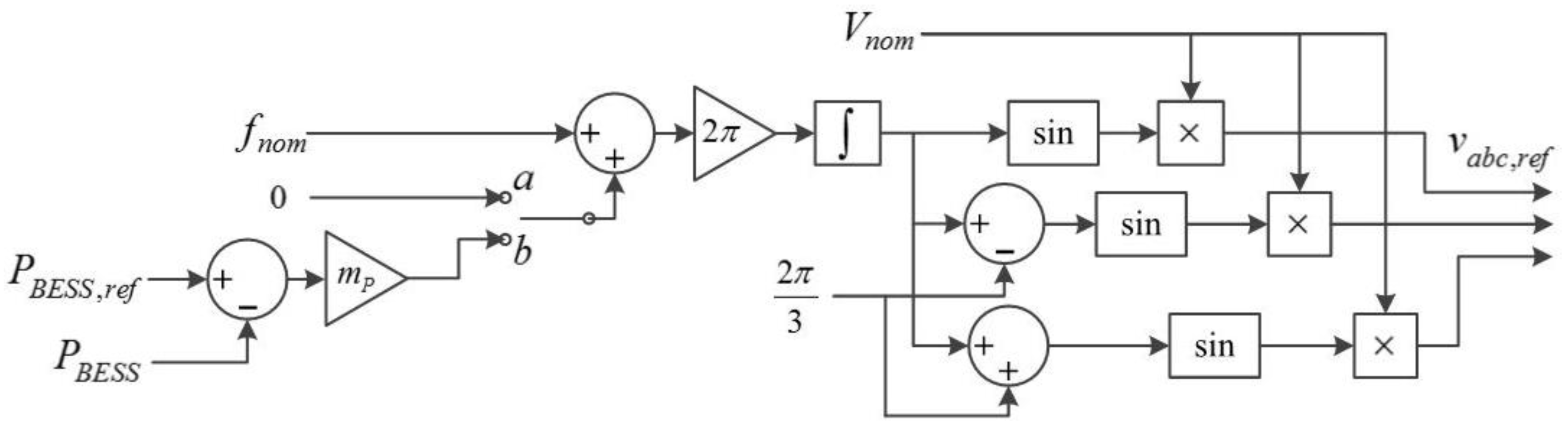
A BESS operated as a CF control mode must be connected in a standalone microgrid in order to apply the proposed method. In this case, only a single BESS must be operated as a CF control mode. By applying a CF control mode to the BESS, the output active power of the BESS (and only the BESS) responds to all changes of load conditions, such as changes of load or RESs’ output. If other DGs or BESSs are operated in a frequency control mode, they also respond to the load change either. To prevent for them to respond, the other DGs and/or BESSs must be operated in a PQ control mode. The control scheme of the BESS is shown in
Figure 2.
Figure 2 shows the BESS controller, where
fnom is the nominal frequency,
Vnom is the nominal voltage magnitude,
PBESS and
PBESS,ref are the output active power of the BESS and its reference value, respectively,
mp is the frequency droop coefficient, and
vabc,ref is the reference voltage of the inverter of the BESS. The droop coefficient
mp (which is 0.0083 in this study) is determined by dividing allowable frequency range (0.5 Hz = 0.0083 pu) by the maximum output power of the BESS (1 MW = 1 pu). In normal condition, switch is connected to node
a, whereas in abnormal condition, such as a case that the SOC data cannot be sent to other DGs due to communication failure, the switch is connected to node
b. In this way, the BESS is operated to maintain CF in normal condition. By using the BESS as the only frequency control mode unit, the BESS responds to all changes of load condition. If there are two or more BESSs in the system, only one BESS must be controlled in CF control and the others must be controlled in PQ control mode in order to apply the proposed control strategy.
If the communication system fails, the present SOC level of the BESS cannot be delivered to other DGs. Thus, to enhance the system reliability, the switch is connected to node b if the communication system fails in order for the BESS to be operated as the conventional P-f droop control mode and then the other DGs sense the load change by the frequency deviations.
However, the BESS has a capacity limitation which leads the BESS unable to operate consistently if it becomes fully discharged. To overcome this problem, other controllable DGs are controlled to maintain the SOC at a certain level and to share the active power of the system. These types of DG units are categorized as primary and secondary SOC control units as similar as the conventional primary and secondary frequency control units.
By using the BESS as a CF control mode unit and the other DGs as PQ control mode units, two problems related to the rating of the BESS may happen. The first one is that the output power of the BESS may exceed its power rating if a large transient load change occurs. The other is that the BESS may be fully discharged since it cannot control its active power directly. To overcome these problems, some of the controllable DGs in a microgrid have to support transient load change and the others have to maintain the SOC within an allowable range. The primary and the secondary SOC control units are for the former and the latter, respectively. Also note that it is profoundly significant for the BESS not to be fully charged or discharged because the CF control mode cannot be maintained in this case. In this case, some of other controllable DGs must change their control mode to the conventional
P-
f droop control mode. The control scheme of the
P-
f droop control mode is same as shown in
Figure 2 with the switch connected to node
b.
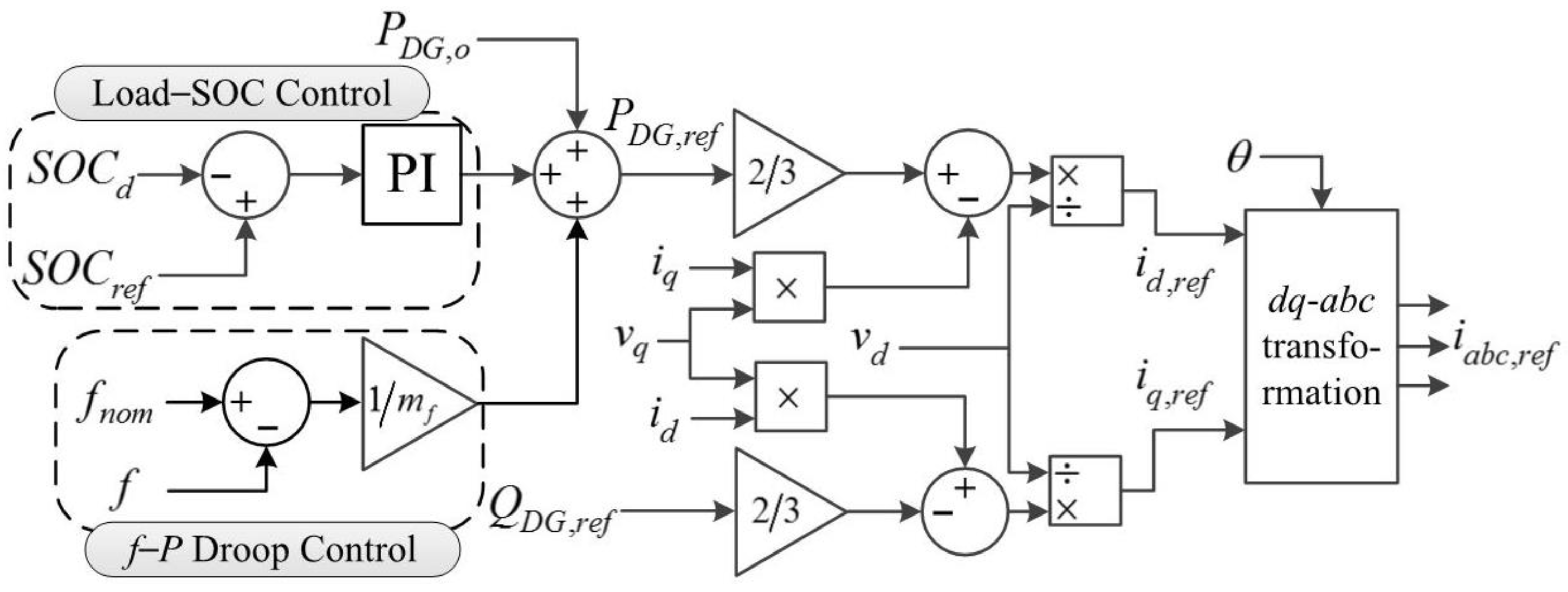
2.3. Primary State of Charge Control
Figure 3 shows the control scheme of the primary SOC control DG unit, where
ms is the droop coefficient (
Figure 1),
PDG,o is the dispatched active power,
PDG,ref and
QDG,ref are the PQ reference, respectively,
vd and
vq are
d- and
q-component output voltage, respectively,
id and
iq are
d- and
q-component output current, respectively,
id,ref and
iq,ref are the reference values of
id and
iq, respectively, θ is the reference angle of the grid-side
d- and
q-axis voltage, and
iabc,ref is the reference current of the inverter of the DG. The control principle of the primary SOC control unit is shown in the following equation:
which is given by substituting Equation (4) into Equation (3). Since the PQ (
P and
Q, respectively) can be expressed as:
id,ref and
iq,ref can be rearranged as:
Note that the primary SOC control unit should be installed at the same bus with the BESS since it should rapidly sense the output power of the BESS (see
Figure 3 that the primary SOC control unit receives
PBESS as an input) without any communication delay. Consequently, the primary SOC control unit can share transient load change with the BESS. The amount of power sharing can be adjusted by varying
ms. With a small
ms, which means that the primary SOC control unit takes a large portion of responsibility for transient load change, the power rating of the BESS can be decreased. However, too small
ms can cause the control instability. So it should be determined appropriately.
By using the primary SOC control solely, the SOC cannot be restored to the desired value. To maintain the SOC within an allowable range, the secondary SOC control should be adopted to some controllable DG units.
2.4. Secondary State of Charge Control
Figure 4 shows the control scheme of the primary SOC control DG unit, where
SOCd is the SOC value with communication time delay,
SOCref is the SOC reference, and
mf is the frequency-active power (
f-
P) droop coefficient. The load-SOC control in
Figure 4 is to restore the SOC to the reference value if the SOC is deviated from its reference value. The terminology “load-SOC” comes from the load-frequency control of the conventional power system which restores the frequency if it is deviate from its nominal value. Multiple secondary SOC control units can share the SOC deviations according to the PI controller gains. For instance, if the gain ratio of two secondary SOC control units is 2:1, they share active power with the ratio of 2:1 during the SOC restoration.
The
f-
P droop control is to cope with the communication failure. In normal condition, the BESS maintains the CF, and hence the
f-
P droop control does not activate. If the communication fails, the load-SOC control cannot be activated since the SOC data cannot be received. In this case, the secondary SOC control unit shares active power by sensing the frequency deviation as same way as in the case of conventional standalone microgrids. If the switch of the BESS controller is connected to node
b (
Figure 2), the frequency varies as the load condition is changed. With the controller shown in
Figure 4, the secondary SOC control unit can always share active power no matter the communication fails or not. Moreover, it does not need any switch that converts control modes between the load-SOC control and
f-
P droop control.
The coordination process between the BESS, the primary and the secondary SOC control units is as follows:
- (1)
The load (or the RESs’ output power) varies;
- (2)
The output power of the BESS and hence the SOC is changed;
- (3)
The primary SOC control unit supports the BESS by changing its output power based on the output power deviation of the BESS;
- (4)
After a small communication time delay, the SOC deviation is sent to the secondary SOC control units and they restore the SOC to the desired value.
3. System Configuration
Figure 5 shows the microgrid tested in this paper which is referred from [
17,
18] with slight modification. The microgrid’s nominal voltage and frequency are 13.8 kV and 60 Hz, respectively. The standalone microgrid is composed of the loads, the 1-MW/2-MWh BESS, three controllable 2-MW DGs, one uncontrollable 2-MW DG, the transformers, the local controllers (LCs), and the microgrid central controller (MGCC). The MGCC collects the weather and load forecasting data, the SOC data, etc., and then gives references (which are acquired from optimization algorithms) to the LCs which control the DGs and the BESS. It operates as an energy management system (EMS) in the microgrid. However, in this paper, the MGCC is used only for the SOC data exchanging.
Since neither inverter switching dynamics nor harmonics is considered, inverters in the DG units and the BESS are assumed as ideal sources. Since the BESS is controlled as to maintain the system frequency and voltage (CF control mode), it is modeled as an ideal voltage source. The other DG units are controlled as to adjust reactive power (PQ control mode), and hence they are modeled as ideal current sources.
In the simulation, the capacity of the BESS is scaled down to 1/400 of its original value (2 MWh) to see change of the SOC clearly since the total simulation time is about 10 s. The communication time delay of 300 ms was considered to take account of the worst time delay considering that typical communication time delay is in the order of 100–300 ms [
19].
4. Case Studies
Four case studies were tested to prove the effectiveness of the proposed control method. The proposed method was compared with the conventional frequency droop control method. Tested cases will show that by using the proposed control method, the frequency can be maintained constantly at the nominal value with a good system reliability against the communication failure. They also indicate that the secondary SOC units can share active power according to the predetermined ratio.
Table 1 shows the control methods applied to each DG unit.
As shown in
Table 1, the BESS is controlled as
P-
f droop control mode, and DG1–3 are controlled as
f-
P droop control mode in the conventional control method. On the other hand, the BESS is controlled as CF control mode, DG1 and DG2 are controlled as secondary SOC control units, and DG3 is controlled as primary control unit. DG4 is uncontrollable unit, such as a RES, in both the conventional and the proposed control methods.
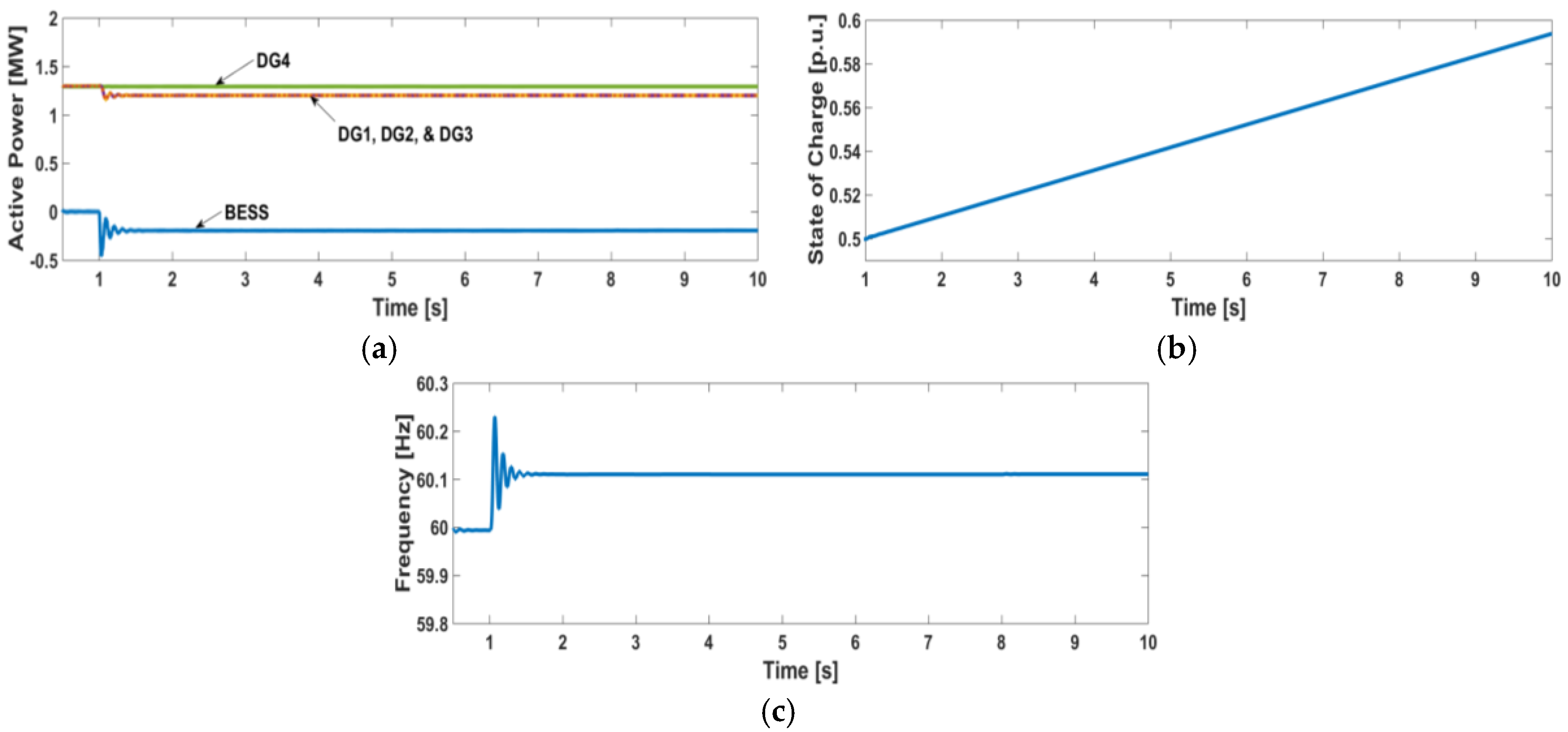
4.1. Case 1—Load Change
In Case 1, a sudden load change of 0.5 MW is occurred at 1 s and the non-dispatchable DG unit (DG4) is assumed to output constant power. Under this circumstance,
Figure 6 shows the simulation results with the conventional frequency droop control method.
From
Figure 6a, it can be noticed that the dispatchable DG units (DG1–3) and the BESS share active power according to the droop coefficients. Since there is no DG unit that recovers the SOC, the SOC is deviated from its reference value (0.5 pu) as shown in
Figure 6b. Moreover, the frequency is also deviated from its nominal value as shown in
Figure 6c.
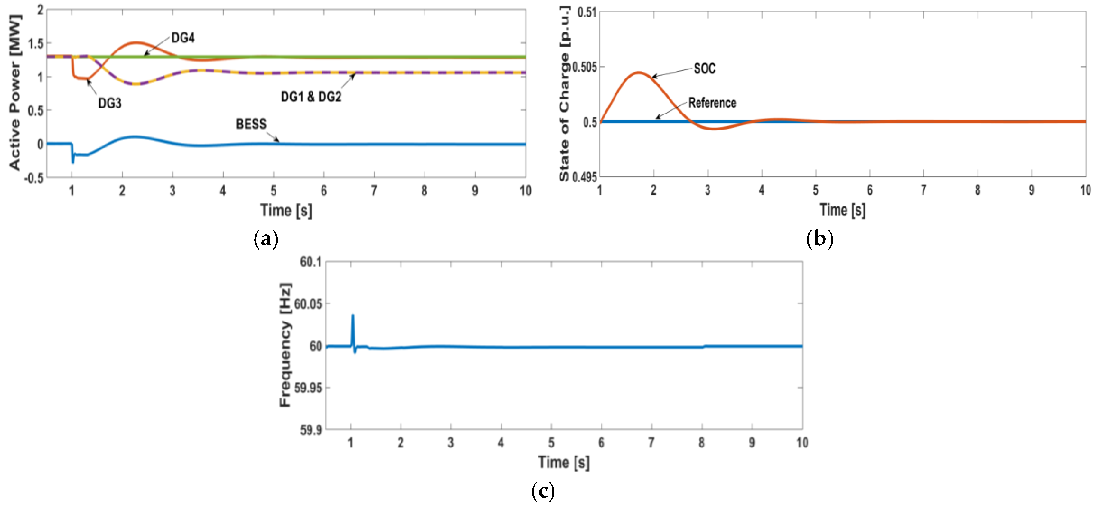
Figure 7 shows the simulation results with the proposed method. After a sudden load change at 1 s, the BESS responds to the load change and the primary SOC control unit (DG3) shares the transient load change. After a time delay of 0.3 s (a time that needs for the MGCC to give an SOC signal to the LCs), the secondary SOC control units (DG1 and DG2) responds to the SOC deviation and activated to restore the SOC. Since the PI gains of load-SOC controller (
Figure 4) of DG1 and DG2 are same with each other, they equally share the active power. Consequently, the SOC is restored to its reference value after a few seconds with zero frequency deviation as shown in
Figure 7b,c.
4.2. Case 2—Load Change with Different Active Power Sharing Ratio
In the previous case, the roles of the primary and the secondary SOC control units are presented. The primary SOC control unit shares the transient load change with the BESS and the secondary SOC control units restore the SOC to the reference value. The secondary SOC control units share the active power with the ratio of 1:1.
In this case, the active power sharing ratio among the secondary SOC control units is adjusted to 2:1 in order to show the active power sharing ratio can be controlled as desired. This means that the active power sharing ratio can be adjusted based on the power rating or the generation cost of each DG unit, the line restriction, etc. The rest of the simulation environment are same as Case 1.
Figure 8 shows the simulation results of Case 2. As shown in
Figure 8a, the active powers of the BESS, DG3 and DG4 are same as those of Case 1, whereas DG1 and DG2 does not equally share active power anymore. DG1 decreases its active power twice as much as DG2 does after the load change since their PI controller gains’ ratio is adjusted to 2:1. The SOC and the frequency are well maintained at the desired values as shown in
Figure 8b,c, respectively.
4.3. Case 3—Intermittent Output Power of Renewable Energy Sources
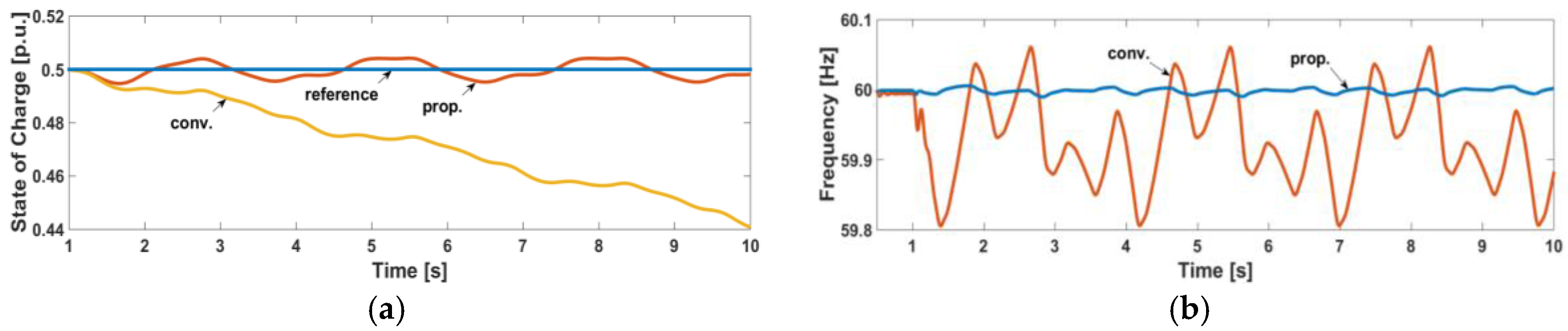
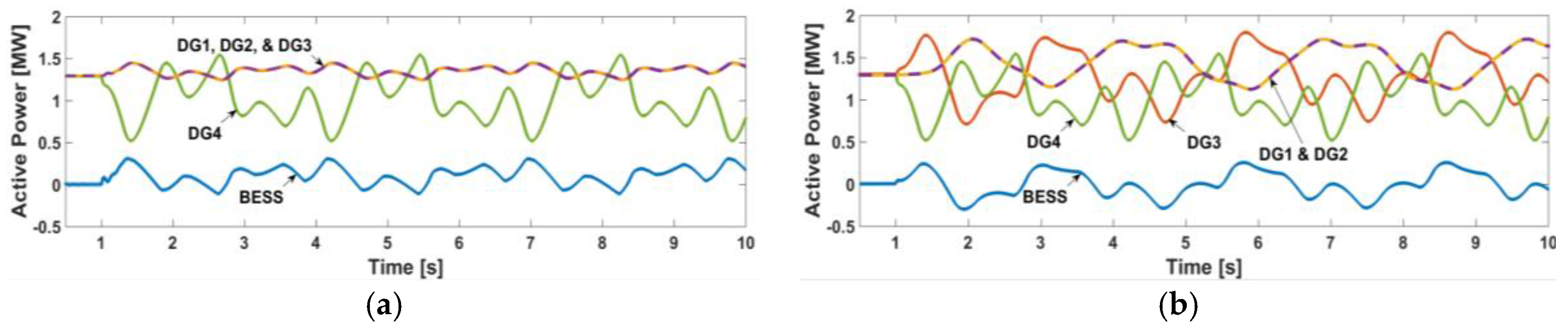
The main purpose of this study is to drastically mitigate frequency deviations during RESs output power fluctuation, thereby to stably increase the penetration level of RESs. In this case, the active power of RES (DG4) fluctuates from 0.5 MW to 1.5 MW.
Figure 9 shows the active power comparison between the conventional method and the proposed method. In the conventional method, DG1–3 share active power change with the BESS by the frequency droop control, whereas only DG3 shares active power change with the BESS in the proposed method. Since the output power of RES changes intermittently, it is hard to distinguish the role of each DG unit.
The advantages of the proposed method are clearly shown in
Figure 10. It shows the SOC and the frequency comparison between two methods. The conventional method and the proposed method are denoted as conv. and prop., respectively, in the graph. By using the proposed method, the SOC can be maintained near the reference value with a small fluctuation. On the other hand, the SOC is dropped continuously in the conventional method.
Figure 10b shows the key result of this study, that is the frequency can be maintained near the nominal value despite of a large fluctuation of the RES power.
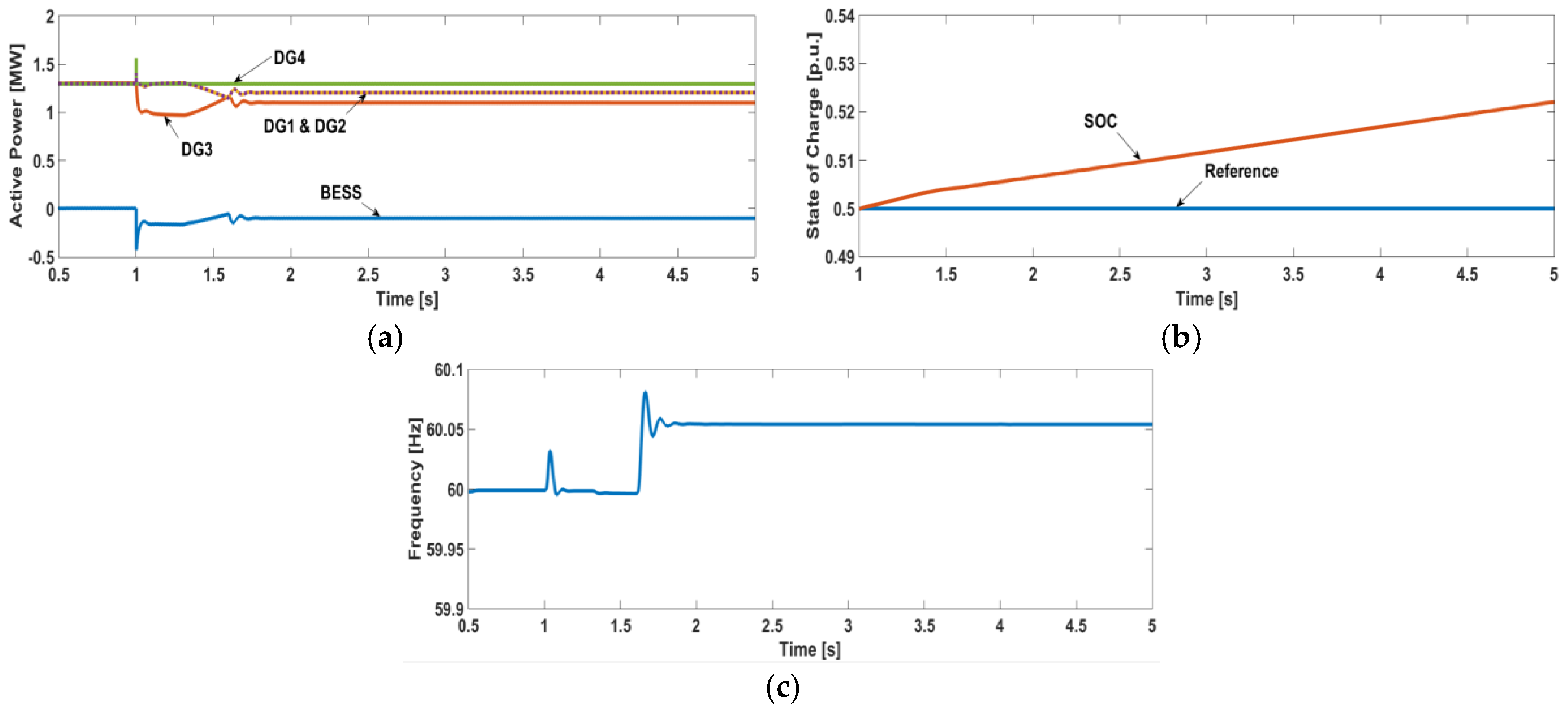
4.4. Case 4—Communication Failure
Though the frequency deviation is dramatically mitigated by using the proposed method, the reliability may be degraded by the dependence of the communication system (remind that the SOC data has to be exchanged via communication system, whereas the frequency data can be acquired anywhere in the grid). In order to increase the system reliability, the control mode change of the BESS by switching (
Figure 2) and the
f-P control term is incorporated into the secondary SOC control unit (
Figure 4). To prove its effectiveness, this case tests the communication failure. The simulation environment is same as that of Case 1 except that the communication failure occurs and the BESS changes its control mode from CF control mode to
P-
f droop control mode at 1.6 s. However, in this simulation, it is assumed that the communication failure is able to be detected by the BESS. The detection of the communication failure in the real case must be discussed further in future works.
Figure 11 shows the simulation results of Case 4. As shown in
Figure 11a, even though the communication fails at 1.6 s, the secondary SOC control units (DG1 and DG2) can share active power by
f-
P droop control term. Regardless of the communication failure, the primary SOC control unit (DG3) can share active power since its active power sharing mechanism is based on the deviation of
PBESS, which is measured directly by DG3 (note that the primary SOC control unit has to be installed at the same bus where the BESS is installed). Since the BESS changes its control mode and the SOC data cannot be exchanged anymore, the SOC and the frequency are deviated from their desired value as shown in
Figure 11b,c, respectively. Though the SOC and the frequency cannot be maintained at the desired value, the system reliability is enhanced by incorporating the frequency droop control with the proposed control method.
5. Conclusions and Future Works
This paper presents a novel method of the active power sharing in a standalone microgrid. Commonly, most of the conventional methods have been used the frequency droop control. However, by using the frequency droop method, the system frequency is inevitably deviated from its nominal value if the load and/or the RESs power are changed. Standalone microgrids are vulnerable to the frequency deviation since they have low system inertia. Hence, the active power sharing method without the frequency deviation is necessary for a standalone microgrid. To this end, the BESS is employed to implement a CF control mode without any droop control. However, the BESS has a capacity limitation which makes the BESS unable to operate consistently. To overcome the capacity limitation problem, other controllable DG units maintain the SOC at the desired value and share the active power based on the SOC deviation. These DG units are categorized as the primary and the secondary SOC control unit. The primary SOC control unit responds instantly as the active power of the BESS is deviated from 0. The secondary SOC control unit receives the SOC data from MGCC. Though sending SOC data has communication delay, the SOC can be well maintained at the desired level with the coordination of the primary SOC control unit. The communication system failure is also considered to enhance the system reliability. If the communication system fails, with the change of the BESS control mode, the system is operated as same as the conventional droop-based microgrid. The effectiveness of the proposed method was proved by the simulation, which is tested and modeled with MATLAB/SimPowerSystems (MathWorks, Natick, MA, USA).
One of the future works is that the proposed control method should test small-signal stability considering communication time delay. In the proposed method, the DG units need communication system which inevitably accompanies time delay. Since the time delay influences the system stability, small-signal analysis should be implemented for robust control.
Determining the PI controller gains of secondary SOC control units may be another future work. In this study, the PI controller gains were arbitrarily determined to show that the secondary SOC control units share active power as per predetermined ratio (ratio among PI gains of secondary SOC controllers). However, they need to be determined with careful consideration, such as generation cost, size of BESS, and power loss.
Furthermore, some experiments have to be implemented to apply the proposed method to the real case. During the implementation of experiments, developing a method to detect the communication failure will be one of the main tasks to be solved.


