1. Introduction
With increasing concerns about energy shortages and environmental pollution, low-grade waste heat recovery technology for power generation has received much attention in the past decades. Various low-grade heat recovery technologies have been developed and are currently employed in diverse applications such as solar thermal power [
1], geothermal energy [
2,
3], biomass energy [
4,
5], and engine exhaust gases [
6]. Among existing technologies, the organic Rankine cycle (ORC) is the most widely utilized because of its simplicity, reliability and cost-effectiveness [
7].
As a power output machine, the expander plays an important role in the ORC system. Expanders come in two types: dynamic (turbine) [
8,
9] and positive displacement (volumetric) [
10] such as rotary vane [
11,
12,
13,
14], scroll [
15,
16,
17,
18,
19], twin screw [
20], single-screw [
21,
22,
23,
24,
25,
26,
27] and reciprocating expanders [
28]. In the medium-low power range, the displacement expander is a better choice than the turbo generator, because the former has a low flow rate, low rotational speed and a high pressure ratio [
29]. In the development of expander technologies for small-scale ORC units, the single-screw expander (SSE) has gained popularity because of its superior characteristics of balanced loads, small noise, long life service, little vibration, and simple structure [
21,
22,
23,
24,
25,
26,
27]. SSE is a good choice for power generating ORC units ranging from 1 kW to 1000 kW.
In practice, the ORC systems often work under varied operating conditions. As a result, SSEs operate under changing operation conditions. There are two main factors affecting the operating conditions of ORC systems and SSEs. One factor is waste heat fluctuation. Waste heat fluctuation leads to different flow rates of the working fluid in the evaporator, so the volumetric flow rate of the working fluid at the SSE inlet changes and the rotational speed of the SSE becomes unsteady because of the changing volume flow rate of the working fluid at the inlet. The efficiency of the SSE and ORC system decreases due to the serious leakage and increased friction caused by the unsteady rotational speed of SSE. The other is the different environmental temperatures caused by the seasonal changes. An environmental temperature fluctuation of 40 °C throughout a year is a commonplace phenomenon in many regions [
30]. This fluctuation causes variations in the back pressure and pressure ratio of SSEs, so the pressure ratio does not match the optimum pressure ratio. Hence, over-expansion or under-expansion loss occurs to some extent for SSEs designed for a fixed volume ratio, and such a loss reduces the efficiency of SSEs and ORC systems. Therefore, developing a method to allow SSEs to operate properly at a certain constant rotational speed with a varying volume ratio under varied operation conditions is important to improve ORC efficiency.
Studies conducted on SSEs are mainly limited to experimental work, although some SSE prototypes have been built and tested. Wang et al. [
22,
23] conducted a series of performance tests on a SSE prototype with 117 mm diameter rotors using compressed air as the working fluid. The experimental results showed that the performance of the prototype was acceptable. Based on comparison between the performance of prototypes with different gate rotor/shell and screw/shell gaps, they concluded that the prototype with a medium gate rotors/shell gap of 0.04 mm and a screw/shell 0.05 mm gap demonstrates the best overall performance, with an expander shaft efficiency of 60%. He et al. [
24] investigated the influence of intake pressure on the performance of a self-developed SSE with a 175 mm diameter rotor. Aside from obtaining the performance parameters of the SSE from a test, they discovered a negative effect of high backing pressure values on the power output. Zhang et al. [
25] conducted an experimental study on the influence of rotational speed on the performance of an air-powered SSE prototype with a 175 mm diameter rotor. The optimum performance of the prototype was obtained at an intake pressure of 15 bar, at which the variations in torque, power output and overall efficiency of the SSE were analyzed respect to the rotational speed. Zhang et al. [
26] established an experimental test-bench for a diesel engine-ORC combined system by using SSEs with 155 mm diameters. The ORC and SSE performances were investigated under different diesel working conditions and SSE torques. The results showed that the maximum ORC efficiency was 6.48% when the output power of diesel engine was 250 kW and the SSE torque was 64.43 Nm. Desideri et al. [
27] tested the performance of an ORC system with a reverse single-screw compressor serving as expander in low-grade waste heat recovery with two different working fluids, SES36 and R245fa. They found that the maximum electrical isentropic efficiencies of the system with SES36 and R245fa were 60% at 3000 rpm and a pressure ratio of 8.8 and 52% at 3000 rpm and a pressure ration of 6.8, respectively.
As revealed by previous experimental studies, working condition changes consequently change the optimum operating point related to the rotational speed and pressure ratio for SSEs with a fixed built-in volume ratio. Conventional SSEs cannot be guaranteed to operate with a high efficiency point when the operating point differs from the optimum operating point. To improve the efficiency of SSEs under varied operating conditions, the first step is to make an SSE with a fixed rotational speed to fit the flow rate changes of working fluid. The second step is to find an optimum pressure ratio to eliminate under-expansion or over-expansion losses. However, there is no available literature regarding how to design a SSE with optimum rotational speed and variable built-in volume ratio to improve the performance of SSEs under varied operating conditions.
In this study, slide valves were used to adjust the rotational speed and built-in volume ratio of SSEs so that the expander can adapt to changing working conditions. The geometric analysis provided below is expected to provide a theoretical and technical basis to develop suitable slide valves for SSEs working under such varied operating conditions.
2. Slide Valve
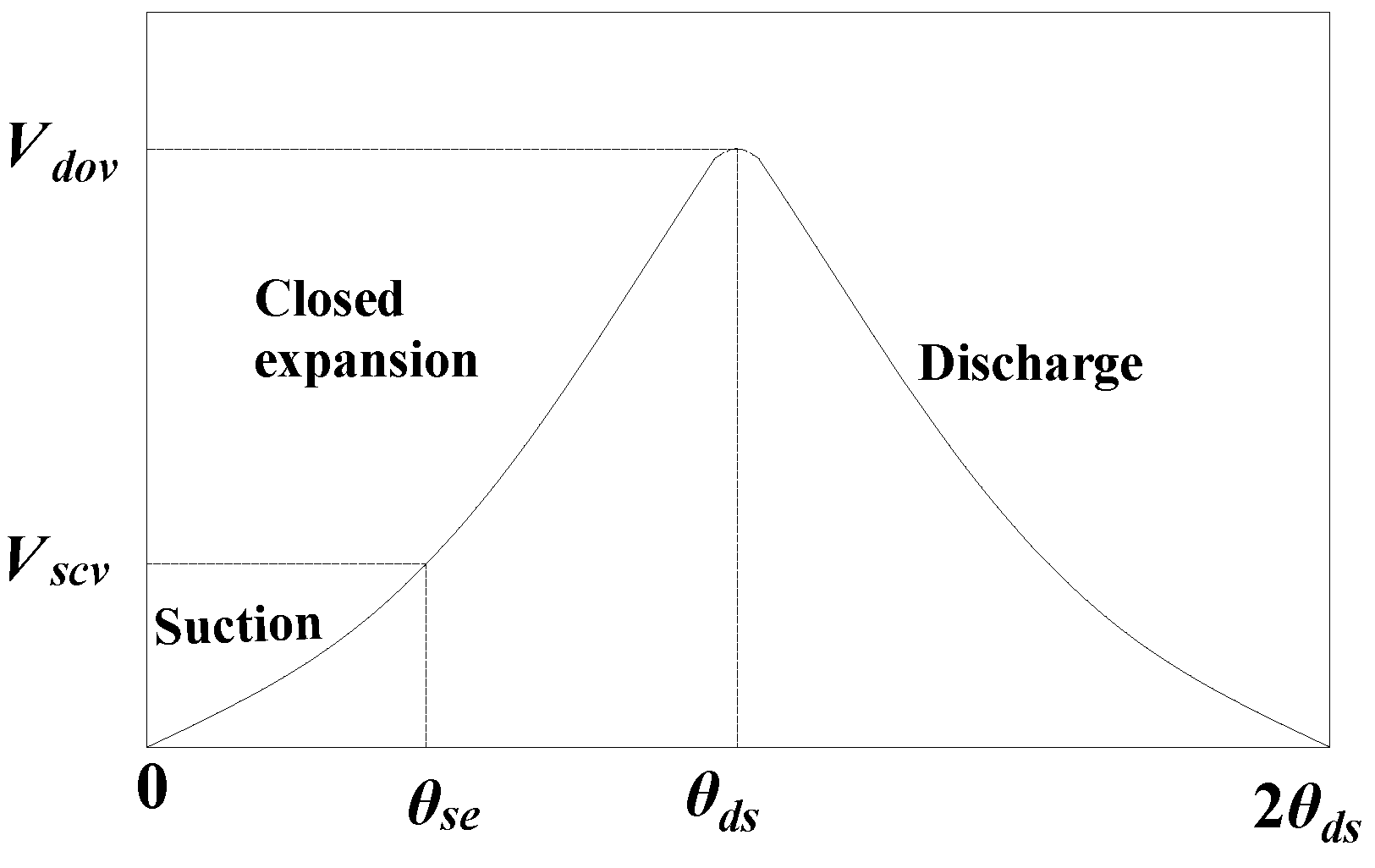
As shown in
Figure 1, the entire working process of an SSE is divided into three phases, i.e., the suction, the closed expansion and the discharge. In the suction process, the suction closure volume
of SSE gradually increases with the increase in the rotary angle of the gate rotor. When the rotary angle of the gate rotor increases to the suction ending angle
, the suction process ends, and the closed expansion process begins. The basic volume continues to increase until the rotary angle of the gate rotor approaches the discharge starting angle
. At this time, the closed expansion closure volume reaches the highest point (discharge opening volume
). Then the expander begins to discharge.
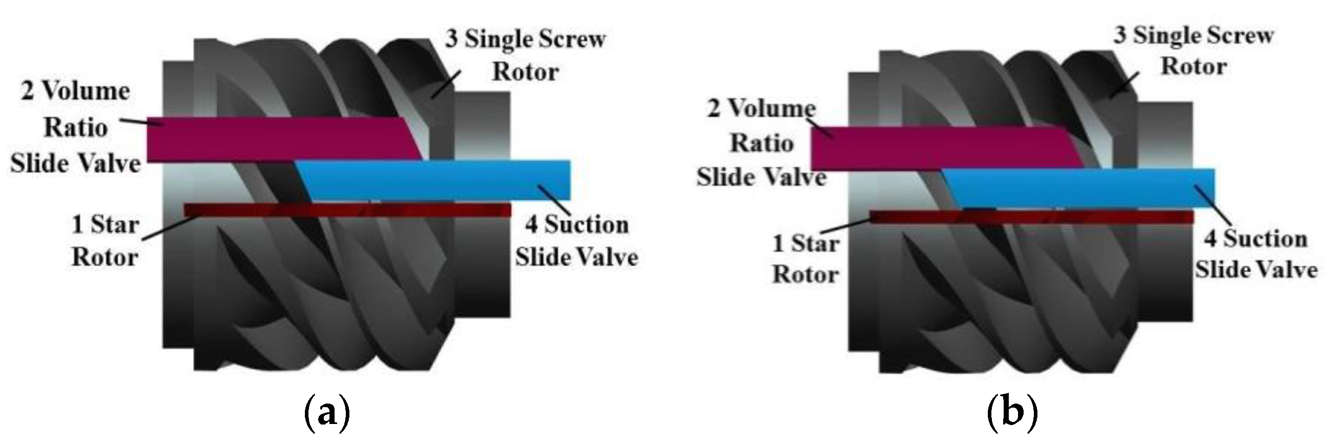
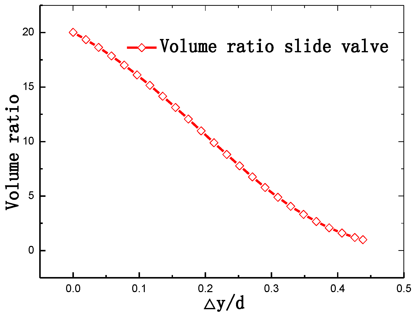
A suction slide valve is introduced to adjust the suction closure volume . A suction slide valve is a slide valve that can move in the axial direction between the single-screw rotor and the gate rotor, and can control the suction closure volume by changing the axial displacement of the suction slide valve. A volume ratio slide valve is introduced to change discharge opening volume . This slide valve can move in the axial direction between the single-screw rotor and the gate rotor, but it controls the discharge opening volume by varying the axial displacement of the volume ratio slide valve.
Both the suction and the volume ratio slide valves themselves constitute part of the housing. The inner side of the two valves is fitted with the top circle of single-screw rotor. And their outer side of them is fitted with the housing. The two slide valves can move freely in the axial direction, and their movement is usually controlled by a hydraulic system.
In
Figure 2a,b, the blue slide valve is the suction slide valve and the red one is the volume ratio slide valve. In
Figure 2a, the suction and the volume ratio slide valves are assumed to be located at the design position. Equation (1) shows that if the inlet flow decreases, suction closure volume
needs to decrease to maintain a stable SSE speed. Hence, the suction slide valve moves leftwards in the axial direction, as shown in
Figure 2b. Equation (2) shows that discharge opening volume
is required to decrease to obtain the same volume ratio. Thus, the volume ratio slide valve moves leftwards in the axial direction, as shown in
Figure 2b:
4. Thermodynamic Model of the ORC System Based on SSE Integrated with Slide Valves
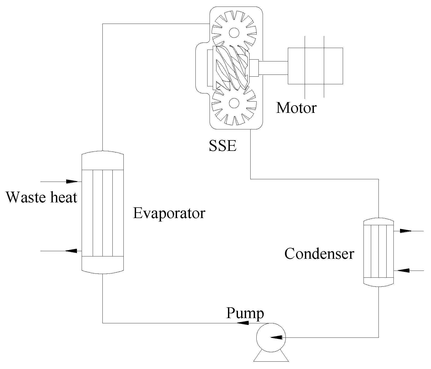
As shown in
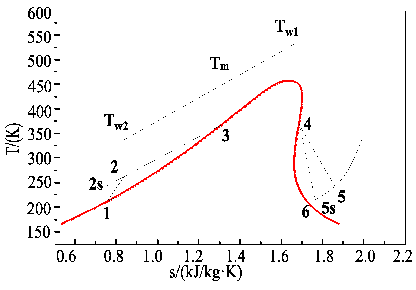
Figure 10, this ORC system is mainly composed of an evaporator, an SSE, a condenser and a pump. The SSE serves as an output power machine. The working fluid is R123. The T-s diagram of the ORC system is shown in
Figure 11.
The working fluid is heated in the evaporator by waste heat, and turns into vapor under high temperature and high pressure. This process is the isobaric endothermic process of the working fluid in the evaporator (evaporation process 2–4 in
Figure 11). Then the vapor expands in the SSE to produce work and turns into vapor with low pressure and low temperature. This process 4–5 in
Figure 11 is the corresponding expansion process. Process 4–5 is the isentropic expansion process. The vapor with low temperature and pressure flows into the condenser and releases the heat so that the working fluid transformed back into liquid. This process is 5–1 condensing process in
Figure 11. Finally the working fluid is sent into the evaporator by the pump (1–2 compression process and 1–2
S isentropic compression process in
Figure 11) and the cycle is completed.
According to the energy conservation principle and assuming that the heat transfer losses in the heat exchangers are disregarded, the released heat by waste heat is equal to the heat absorbed by working fluid in the evaporator. When the working fluid is sent into the evaporator, the absorbed heat can be written as:
The volume flow rate of SSE can be obtained as:
The output power of SSE can be expressed as:
The pressure ratio and optimum pressure ratio can be explained as:
In this study, the working fluid is R123. The exponent
is equal to 1.19 which is an empirical value. Without the slide valves, the shaft efficiency of SSE
can be estimated by an empirical formula Equation (14) given by Desideri et al. [
31]. When a SSE is integrated with both suction and discharge slide valves, the rotational speed of SSE can be maintained at an optimum value and the pressure ratio can be adjusted at an optimum pressure ratio so that neither under expansion nor over expansion losses occurs. Hence, the shaft efficiency of SSE
is equal to the optimum shaft efficiency of expander
:
with:
where the parameters
,
,
,
and
have a mathematical meaning described in
Table 1.
When the working fluid with low pressure enters the pump, the compressibility of the working fluid can be disregarded. Thus, the power consumption of the pump can be written as:
According to a previous work [
32], pump efficiency is very low when the fluid is organic. Hence, pump efficiency
is set to 0.25.
The net power output of the ORC system can be written as:
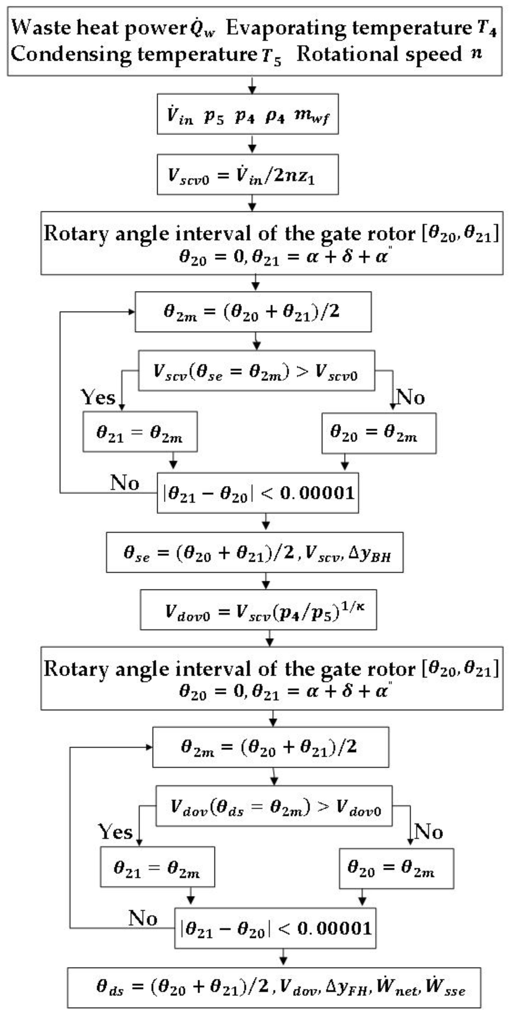
Based on the thermodynamic model of ORC with SSE integrated with slide valves as expander, the calculation flow chart is displayed in
Figure 12.
5. Results and Discussion
A SSE with a 155 mm diameter rotor is utilized to produce output power in a truck engine-ORC combined system and the main parameters are shown in
Table 2. The tooth width of the gate rotor is 23.4 mm. The design volume ratio is 5. The rotary speed of the SSE adjusted by slide valves is maintained at 3000 rpm and the optimum shaft efficiency is thought as 60%. The original position of the suction slide valve is set as the positon where the volume ratio is 5 and the discharge opening volume is the biggest. The original position of the volume ratio slide valve is the position where the discharge opening volume reaches the highest value. When the working fluid R123 flows into SSE, it is saturated vapor at 120 °C as assumed. When it flows out of the condenser, it is assumed to be at saturated condensing temperature. The condensing temperature ranges from 30 °C to 40 °C.
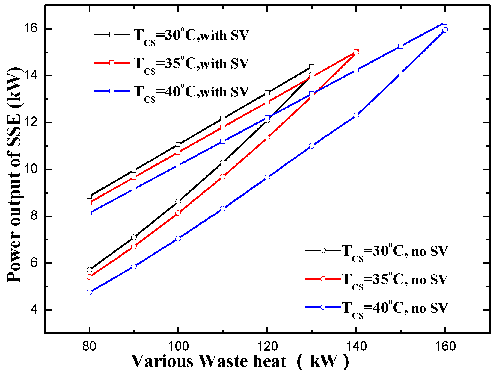
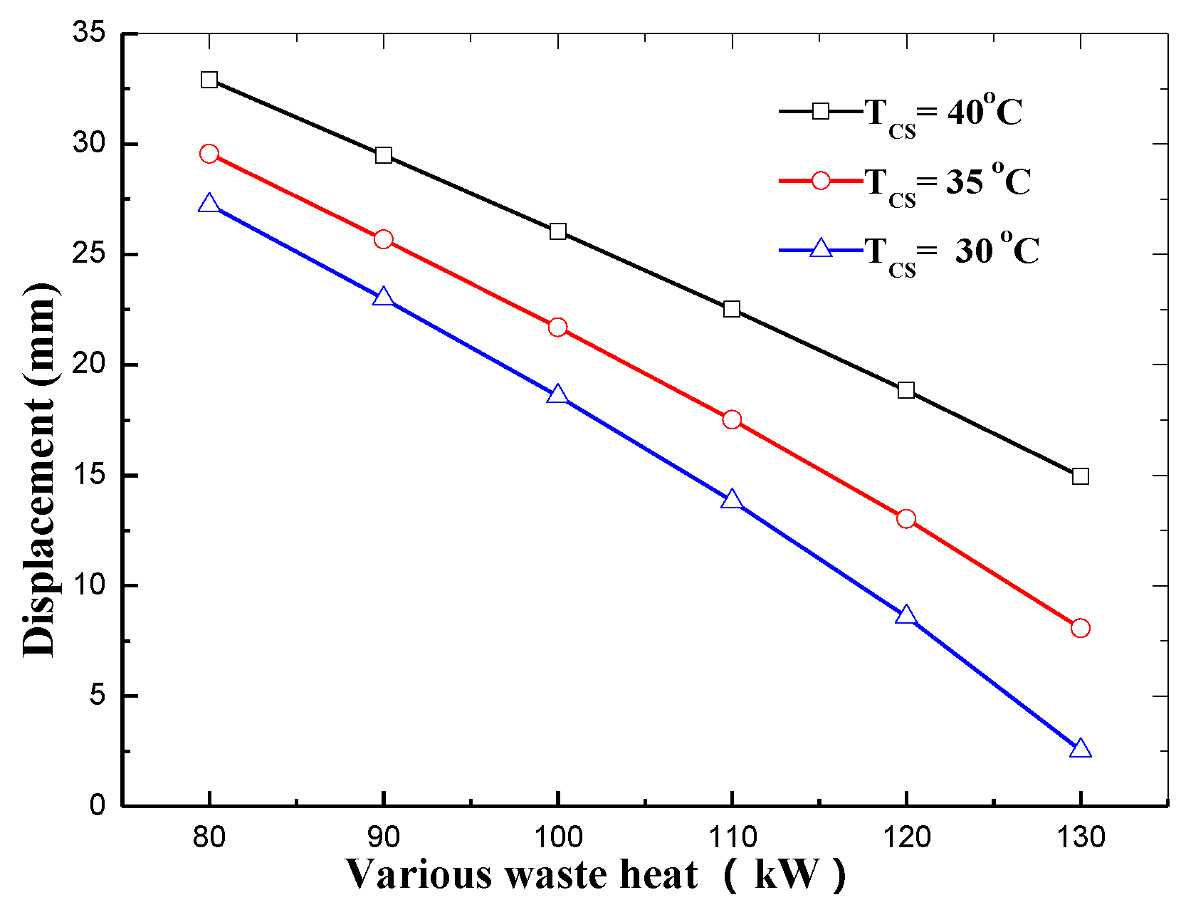
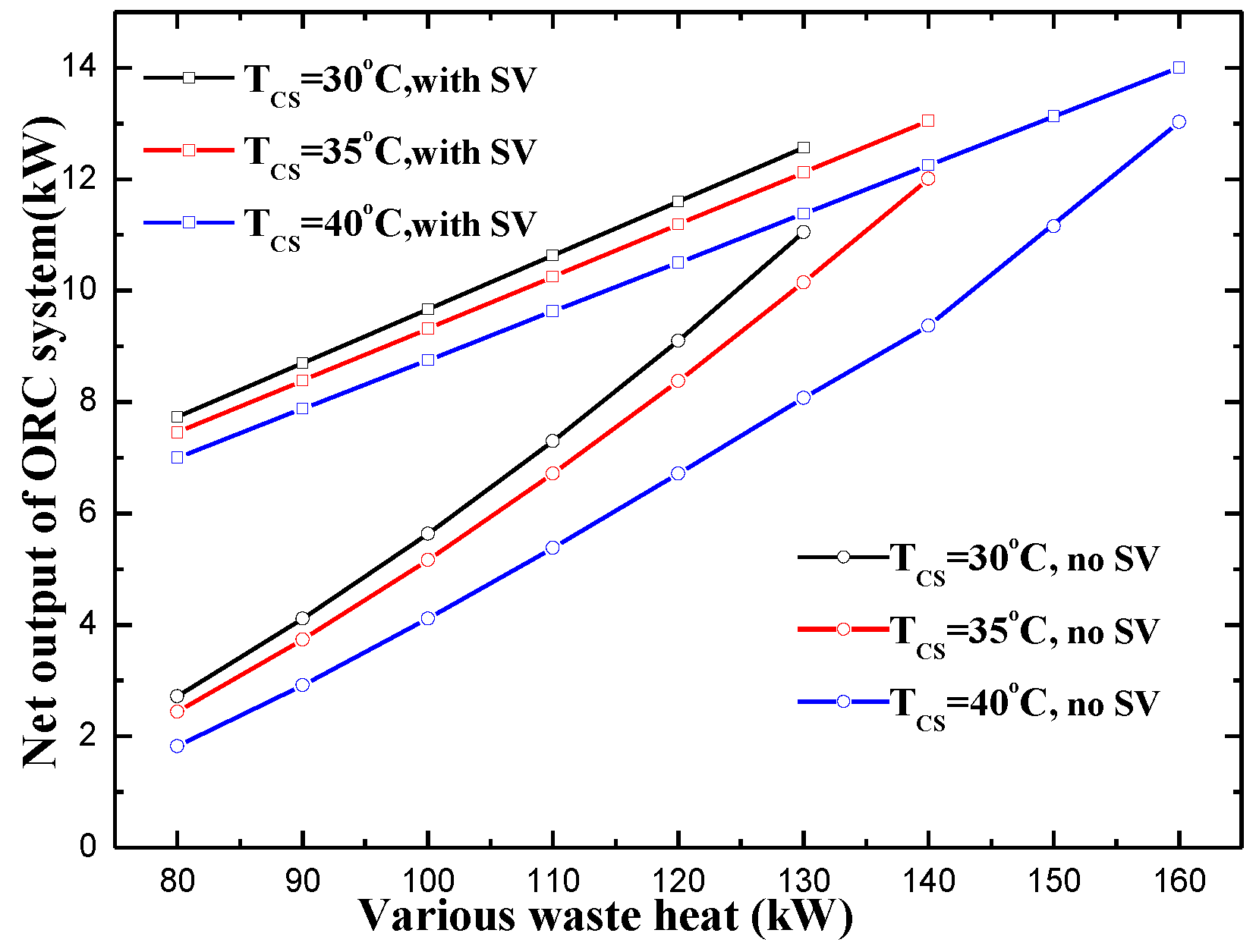
Now, SV represents the slide valve in the following figures. From
Figure 13 and
Figure 14, it can be seen that, under the same condensing temperature, the power output of SSE and the net power output of ORC system with slide vales are greater than that of SSE without slide valves. Under the same condensing temperature, the increase in power output and net output power for ORC system and SSE by using slide valves become greater with decrease of waste heat availability. When the condensing temperature is 40 °C and the waste availability is 80 kW, the increase in output power and net output power is approximately 3.4 kW and 5 kW, respectively. The suction slide valve makes the SSE run at a fixed speed and the volume ratio slide valve prevents it from under-expansion and over-expansion, and thus the SSE can work at a better efficiency point. After adding both the suction slide valve and the volume ratio slide valves for a SSE, the power output and the net power output increases linearly with the growth of waste heat availability, as can be seen from the power output and net power output equation, i.e., Equations (11) and (24). Therefore, the power output of SSE and the net power output
of ORC system with suction and volume ratio slide vales are proportional to the waste heat
.
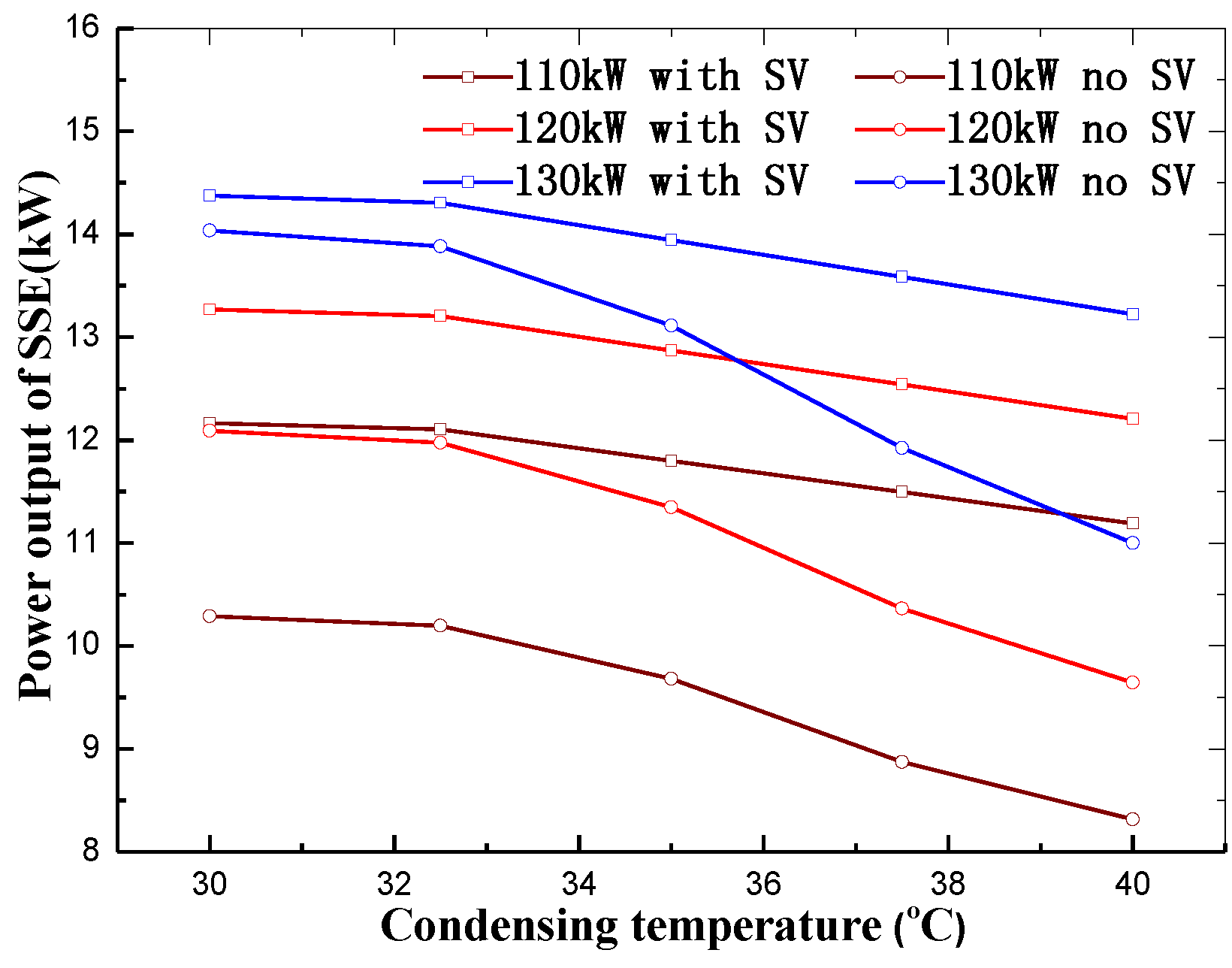
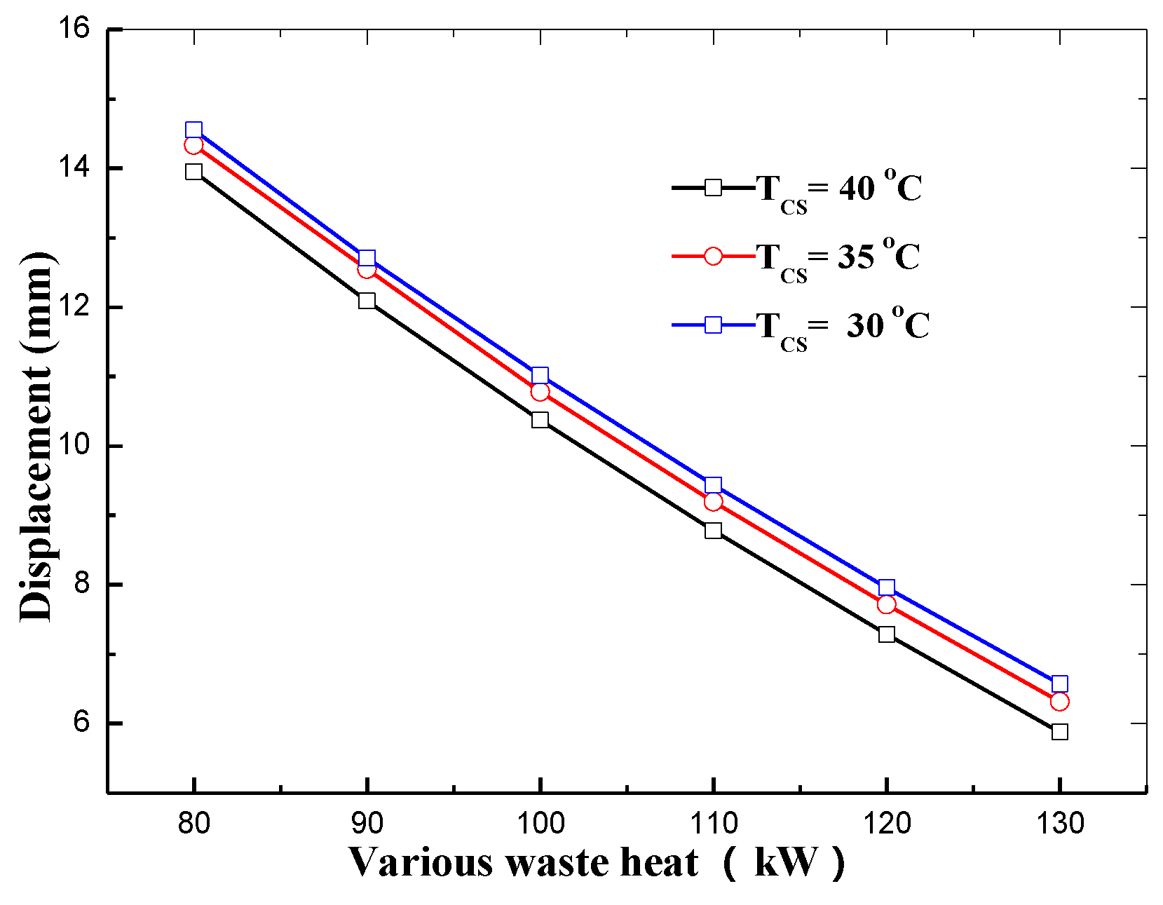
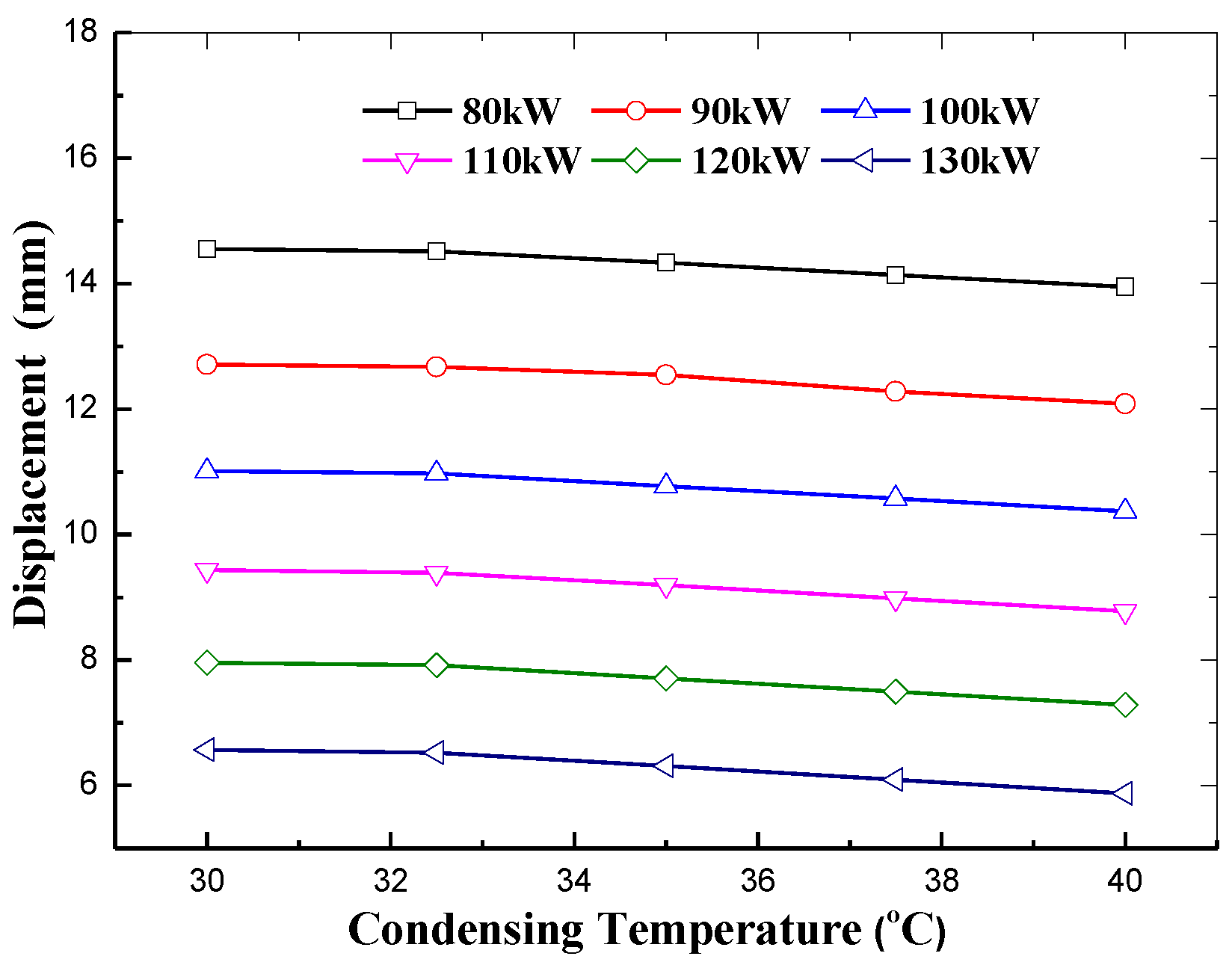
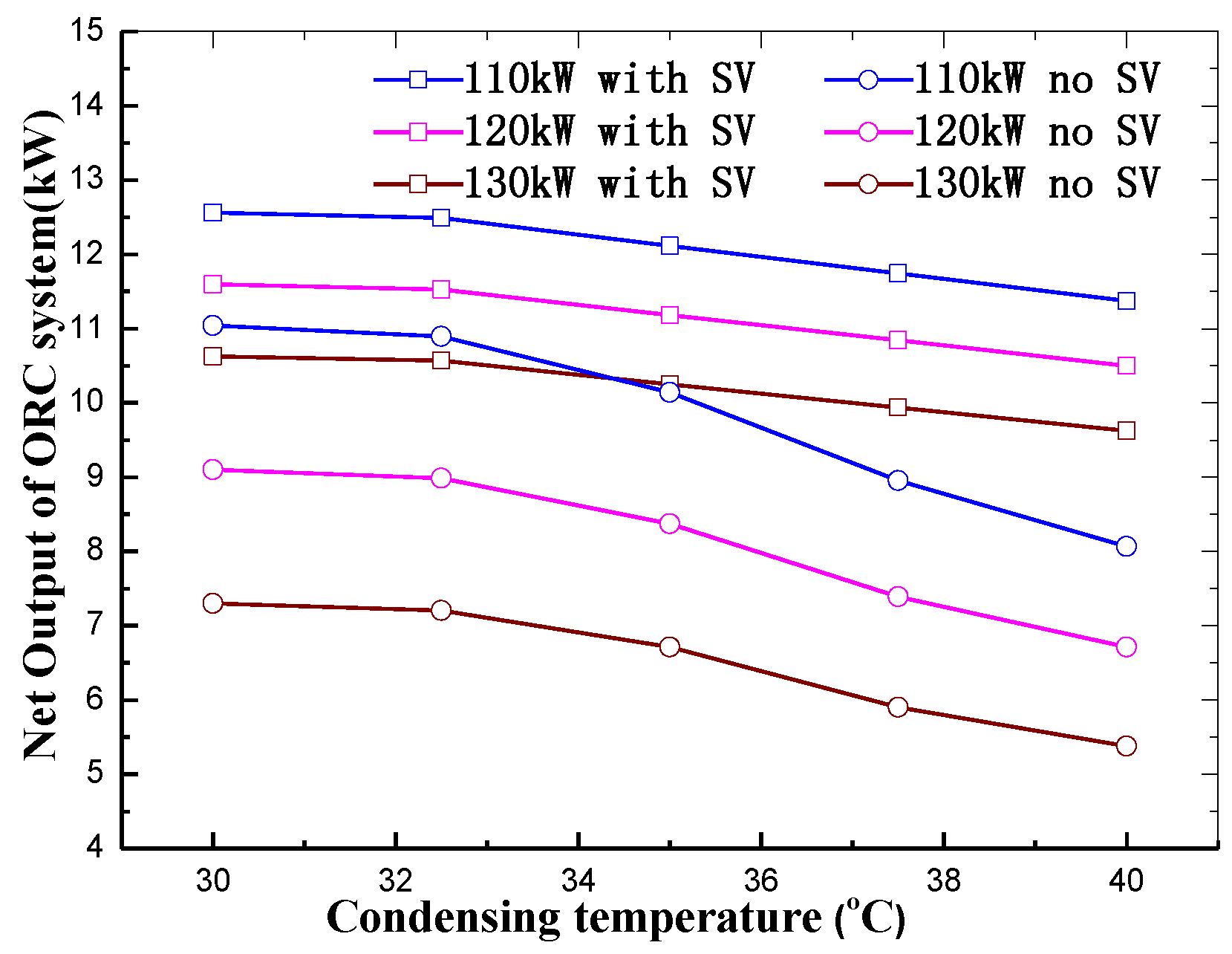
As shown in
Figure 15,
Figure 16,
Figure 17 and
Figure 18, at the same waste heat availability, there is an almost linear increase for the power output of SSE with slide valves with decrease of condensing temperature; and the net power output of ORC system with the suction slide valve and volume ratio slide valve also increases with decrease of condensing temperature and there is a nearly linear increasing trend. Equations (11) and (24) illustrate that, under the same amounts of waste heat, the net power output is mainly related to adiabatic enthalpy value
and condensing pressure
. The adiabatic enthalpy value
is also related to condensing pressure
and inlet enthalpy of SSE.
The evaporating pressure and temperature are assumed to be a fixed value, so the inlet enthalpy of SSE is also a constant. Therefore, the power output and net power output are mainly related to condensing pressure
. For this reason, the power output of expander and the net power output of the ORC system tend to change with the change in condensing temperature in a nearly linear manner. When the volume ratio is 5, the position of the suction slide valve and volume ratio slide valve are set to the initial position. If the displacement of slide valve is greater than 0, the slide valve moves towards left, and vice versa. As indicated in
Figure 19, under a constant condensing temperature, with growth of waste heat, the leftward moving distance of the suction slide valve decreases approximately linearly and finally the slide valve moves toward right side of the design position. When the waste heat increases, there will be a growth for the volume flow rate of working fluid at the inlet of SSE. In order to maintain the stable speed of SSE, the suction closure volume needs to increase so that the suction ending angle needs to increase. Thus, the suction slide valve moves towards the direction that can increase the suction ending angle with increase in waste heat.
As shown in
Figure 20, under the same waste heat, a gradual decrease in the leftward moving distance of the suction slide valve occurs when the condensing temperature increases. When the condensing temperature increases, the enthalpy at the condenser outlet increases and the pump consumption decreases. However, the outlet enthalpy increment of the condenser is greater than the reduction of pump consumption. Thus, the inlet volume flow rate of SSE increases with increase in condensing temperature. In order to obtain a fixed speed, the suction closure volume needs to increase, which means that the suction ending angle needs to increase as well. Therefore, the leftward moving distance of the suction slide valve reduces with increase in condensing temperature.
As illustrated in
Figure 21, under the same condensing temperature, the leftward moving distance of the volume ratio slide valve decreases with the increase in waste heat availability. When waste heat availability increases under the same condensing temperature, the mass flow rate increases and the outlet volume flow rate of SSE increases. In order to obtain a fixed speed and prevent under-expansion and over-expansion, the discharge opening volume needs to increase. This means that the discharge starting angle needs to increase. Therefore, there is a decrease in the leftward moving distance of the volume ratio slide valve when the waste heat availability increases.
In
Figure 22 it is indicated that, under the same waste heat conditions, the moving distance of the volume ratio slide valve increases with increase in condensing temperature. Under the same waste heat availability, when the condensing temperature increases, the back pressure of SSE increases. Thus the pressure ratio will decrease with increase of condensing temperature. In this study, the adiabatic index was set to a certain value. As shown in Equations (12) and (13), the volume ratio decreases with increase in condensing temperature. When the condensing temperature grows, the suction closure volume increases and causes the volume ratio decrease. However, the decrement cannot make optimum pressure ratio equal to the pressure ratio. Thus, the discharge opening volume also needs to decrease. The discharge starting angle needs to decrease to obtain a smaller discharge opening volume. Therefore, an increase in the leftward moving distance of the volume ratio slide valve occurs when the condensing temperature increases.
6. Conclusions
The purpose of this study was to provide a theoretical and technical basis for designing an SSE with a constant rotational speed and varied volume ratio to allow the expander to adapt to changing operating conditions. Therefore, the working principle of the slide valves in SSE has been fully described and a geometric analysis of suction/volume ratio slide valves was conducted to obtain the relations between slide valve displacement, suction closure volume, discharge opening volume, and volume ratio. Based on the description and geometric analysis of slide valves, a thermodynamic model of an ORC system based on SSE integrated with slide valves was designed to analyze the power output of SSE, the net power output of ORC and the variation rules of slide valve displacement under different operating conditions and different condensing temperatures.
From an example of an ORC system-based SSE with a 155 mm diameter screw rotor, it can be found that the power output and the net power output of the ORC with slide valves exhibits a significant improvement when compared with that of ORC without slide valves. It is also observed that the suction/volume ratio slide valve displacement changes approximately linearly with changing waste heat and changing condensing temperature. Hence the control strategy of slide valve can be easily used for SSEs. The proposed slide valves can be utilized to allow an SSE working at an optimum efficiency point under varied working conditions, which is of great importance in improving the power output for SSE and the net power output of ORC systems integrated with SSE under varied operation conditions.


