1. Introduction
The “smart grid” paradigm envisages a massive presence of non-programmable renewable energy sources: in this context, battery energy storage systems (BESSs) are liable to play a key role at both distribution and transmission level, given their potential ability to fulfill roles such as load shifting, peak shaving, frequency and also voltage control [
1,
2,
3,
4,
5,
6]. Moreover, BESSs have also been proposed in integration to electric power systems supplying traction and mobility systems, with the aim to maximize the energy efficiency [
7,
8,
9,
10]. In principle, the study of BESS impact on the electric power system should include environmental aspects, optimal siting, as well as power quality issues and harmonic disturbances, in accordance with existing standards [
11,
12,
13,
14,
15,
16,
17,
18]. Generally speaking, technical features such as battery size (in terms of both rated power and energy), efficiency, transient performance, cycling and lifetime depend on the specific application. In order to evaluate the economic return of each application, local energy market rules must be taken into account.
This paper deals with the application of a BESS based on lithium iron phosphate (LiFePO
4) batteries to primary frequency control (PFC). Since conventional power plants are increasingly displaced by (mostly non-dispatchable) generation from renewable energy sources, transmission system operators (TSOs) are looking for new PFC providers to preserve frequency quality. Li-ion BESSs are being evaluated for the PFC role [
19,
20], which entails exacting requirements such as fast response, high number of charge/discharge cycles and wide depth-of-discharge (
DOD); notably, LiFePO
4 batteries look very promising, due to their chemical and thermal stability which could ensure a long lifetime under the PFC cycling conditions at a relatively low cost [
21,
22,
23].
However, to date there is not enough operating experience confirming the PFC applicability and the performances (expected lifetime, round trip efficiency) of LiFePO
4 batteries. To this end, a coupled electrical-thermal model of a LiFePO
4 battery has been developed and validated against experimental tests by Terna (the Italian TSO). The model has been used to simulate PFC operation of a 1-MW/1-MWh LiFePO
4 BESS deployed by Terna, considering different values of droop and discharge rate (
C-rate). The paper is organized as follows.
Section 2 briefly recalls the Terna experimental BESS system, while
Section 3 details the proposed PFC application.
Section 4 deals with BESS modelling; experimental test results are shown in
Section 5 and PFC simulation results are reported in
Section 6.
2. The Terna Experimental LiFePO4 Battery Energy Storage System
There are a significant number of manufacturers of LiFePO
4 batteries, since they use readily available raw materials and are thermally and chemically stable, thus ensuring safety as well as long service life. Moreover, the high power-to-energy ratio makes LiFePO
4 batteries attractive for BESS applications. LiFePO
4 have a lower nominal cell voltage (3.2 V) than other Li-ion batteries. The normal voltage for grid (stationary) application ranges between 2.8 and 3.6 V, in order to increase battery life avoiding operation at extreme values of the state-of-charge (SOC) near full charge or full discharge. The maximum continuous discharge rate of presently available MWh-sized systems can vary from 0.2C [
19] to 4C [
20], depending on the manufacturing technology and module thermal design.
C-rate range requirements vary widely with the specific application: renewable energy sources balancing typically requires
C-rates ranging between 0.2C and 1C, whereas PFC might involve
C-rates ranging between 1C and 4C. Several LiFePO
4 BESS projects have been recently commissioned in China, America and Europe; in Italy, two LiFePO
4 systems have been recently installed by Terna as part of the wider “Storage Lab” [
24,
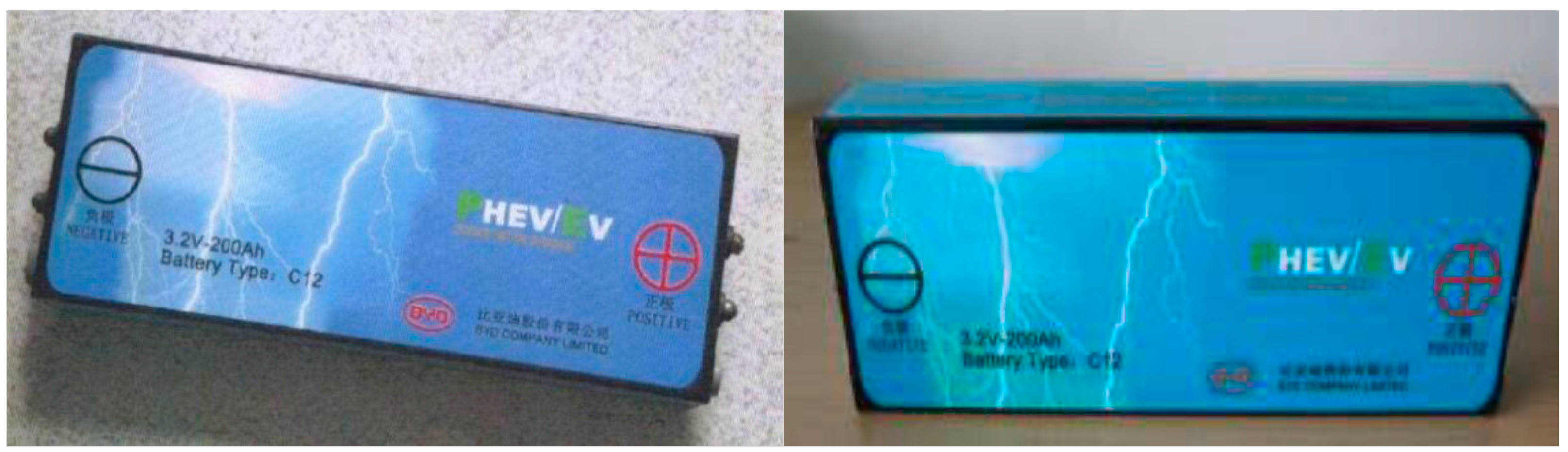
25] experimental BESS project. Terna’s LiFePO
4 BESS is based on prismatic cells (
Figure 1) suitable for stationary applications, located in an aluminum case.
The series connection of four such cells forms a battery module with a 12.8 V-2.37 kWh rating. The battery module is sealed to prevent moisture ingress and to avoid leaks in case of battery failure: as a consequence, the thermal behavior of the cells inside the module differs substantially from that of free-standing cells. Each module is provided with its own battery management system (BMS) for cell balancing and battery monitoring. Modules are series-connected to form battery strings (mounted on racks designed with sufficient spacing for proper ventilation and cooling [
24]), which are paralleled inside the air-conditioned battery container (
Figure 2). Each of Terna’s 1 MW/1 MWh BESS includes a battery container and a dual-stage power conditioning system (PCS) [
26]. The PCS is connected from the low voltage (LV) level to a 20 kV medium voltage (MV) busbar via an integrated MV/LV transformer; the whole system is in turn connected to the Terna 150 kV high voltage (HV) sub-transmission network through a HV/MV transformer.
Extensive testing was carried out on the above described LiFePO
4 batteries, focusing on safety requirements [
27,
28,
29] and battery performance. The latter tests involved intensive cycling of single battery modules (12.8 V-185 Ah) and performance tests on battery string specimens (256 V-185 Ah), with the aim of verifying the expected battery life in normal operation. Moreover, PFC performance was evaluated by cycling a string specimen with a power profile emulating the response of a virtual governor to an actual ENTSO-E (acronym for European Network of Transmission System Operators for Electricity) measured frequency pattern.
The experimental setup included an electronic variable load (model ZS4206, H&H, Konzell, Germany), a controllable dc power supply (SM 15-400, Delta Elektronika, Zierikzee, Netherlands) and a measurement/monitoring system (cFP2220, cFP-AI-118, cFP-TC-120, National Instruments, Austin, TX, USA). This allowed to measure fundamental battery state variables such as current, individual cell voltages and temperatures, subsequently used to estimate battery parameters (resistance, thermal inertia) and performances (round-trip efficiency, battery life). Given the modular design of the BESS, results of tests performed on individual battery strings can be straightforwardly extended to the whole 1 MW/1 MWh system.
5. Results of the Terna Experimental Primary Frequency Control Application
In this section, Terna experimental test results are reported and compared to simulations, in order to validate the electrical-thermal-ageing model presented in
Section 4. The experimental test refers to a one-day period (i.e., 86,400 s), during which the battery string has been cycled by using the frequency profile described in
Section 3.3, with a
C-rate 1C and 0.5% droop. During the test, when the battery was completely discharged, PFC service was interrupted and the battery was completely re-charged (recharge time is 4 h), as in the actual operation of the Terna 1 MW/1 MWh BESS. This full recharge phase is mainly necessary in order to recalibrate the SOC estimation (performed by integrating the current flowing through the battery), which otherwise would be increasingly affected by the accumulation of measurement errors.
Figure 9a shows the comparison between measured and calculated battery string voltage during the one-day period, whereas in
Figure 9b a zoom of the measured and calculated voltages in the time window between
t = 13,000 s and
t = 14,000 s is reported. Simulation results agree very well with measured results when the battery string is performing PFC, whereas substantial differences are evidenced during re-charging in
Figure 9a, approximately from
t = 47,000 s to
t = 62,000 s. These differences are due to the lack of capacitances in the electrical model of the battery, which is more suitable for simulating PFC instead of continuative charge or discharge periods. The small differences between measured and calculated voltage shown in
Figure 9b depend on small mismatches between actual and calculated SOC of the battery. The average error on voltage, calculated as:
equals 6.09 V, i.e., less than 2.4% of rated string voltage.
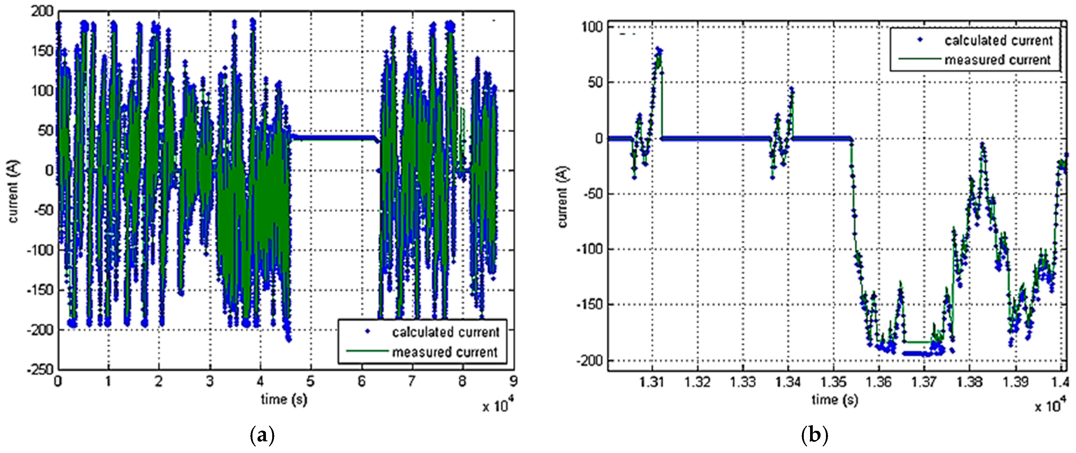
Figure 10a shows the comparison between measured and calculated battery string current during the one-day test period, whereas
Figure 10b details the time window between
t = 13,000 s and
t = 14,000 s. Both figures show a very good agreement: the average error on current is 3.63 A, i.e., 2% of rated current.
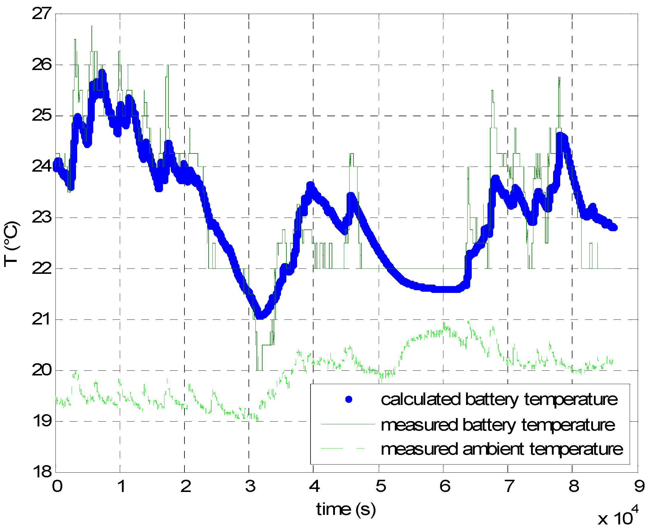
Lastly,
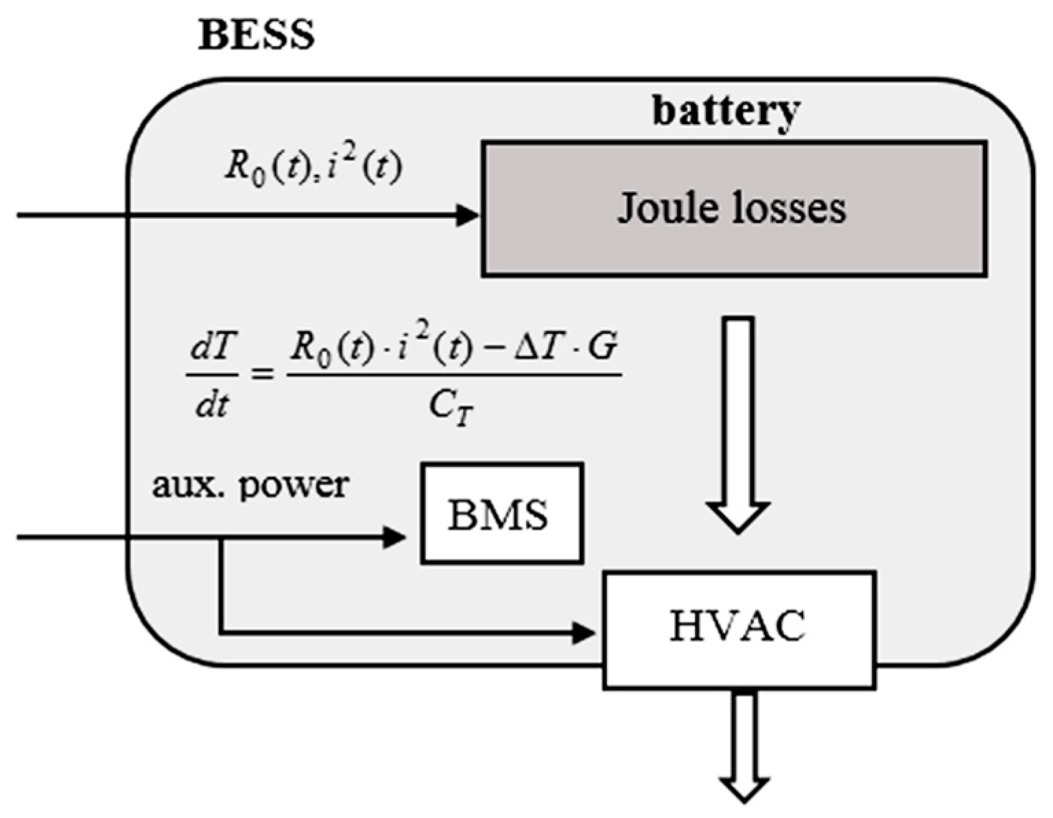
Figure 11 reports the measured and calculated battery mean temperature
Tm (i.e., the average between the temperatures of each cell in the battery string); the measured “ambient” temperature in the cabinet
T0 (i.e., the temperature imposed by the HVAC) is also shown. Measured and calculated values of
Tm are in acceptable agreement, whereas the measured
T0 is always very close to the target value
T0 = 20 °C, thus confirming the approximation made in Equation (2), where Δ
T is calculated considering a constant
T0.
6. Primary Frequency Control Simulation Results
PFC simulations were carried out on a 50 kWh LiFePO
4 battery: since the BESSs is modular, results can be easily scaled to other BESS sizes. PFC operation of the 50 kWh battery was simulated for seven different droop values, namely 0.075%, 0.1%, 0.25%, 0.5%, 1%, 2% and 4%, and four different
C-rate values, i.e., C/2, 1C, 2C and 4C, considering in all cases the frequency profile described in
Section 3.3. Battery performance was evaluated in terms of:
Average number of charge-discharge cycles per day;
Overall battery efficiency η
TOT, including auxiliary consumptions calculated with (3) and assuming 96% PCS efficiency [
26];
Mean temperature, Tm, of the battery in operation (maximum allowed battery temperature Tmax is 55 °C);
Mean C-rate during the whole operation;
Battery power-frequency characteristic λ (kW/Hz);
Expected life;
Unavailability of the battery rack for the PFC service (due to SOC outside the operating range or Tm exceeding the maximum temperature Tmax = 55 °C), in percent of the overall operation time.
Results are summarized in
Table 4,
Table 5,
Table 6 and
Table 7. These also include the equivalent power-frequency characteristic λ (kW/Hz), calculated from rated energy
Wrated (kWh),
C-rate and droop
s:
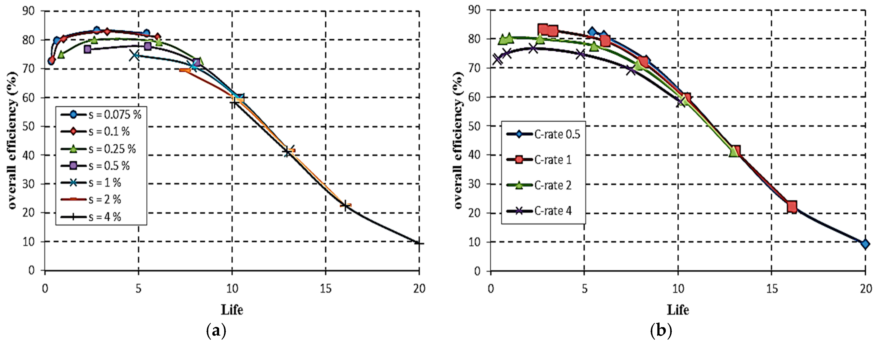
Figure 12 shows that PFC operation with low droop values results in a good overall efficiency, even exceeding 80% as shown in
Figure 12a, especially with the lower simulated
C-rate values as shown in
Figure 12b. Higher efficiencies, however, are traded with expected life values much shorter than the 20 years conventional BESS calendar life, because very low droops are associated to more sustained cycling. This is the limiting factor on efficiency for the extreme simulated combinations of low droop and high
C-rate, which are also associated to the onset of operating constraints such as battery overtemperature and SOC limits, which limit battery utilization. Conversely, low
C-rates combined with higher droop result in much longer battery expected life, at the expense of a sharp decrease in overall efficiency η
TOT due to low battery utilization.
Efficiency and expected life values from
Table 4,
Table 5,
Table 6 and
Table 7 are plotted in
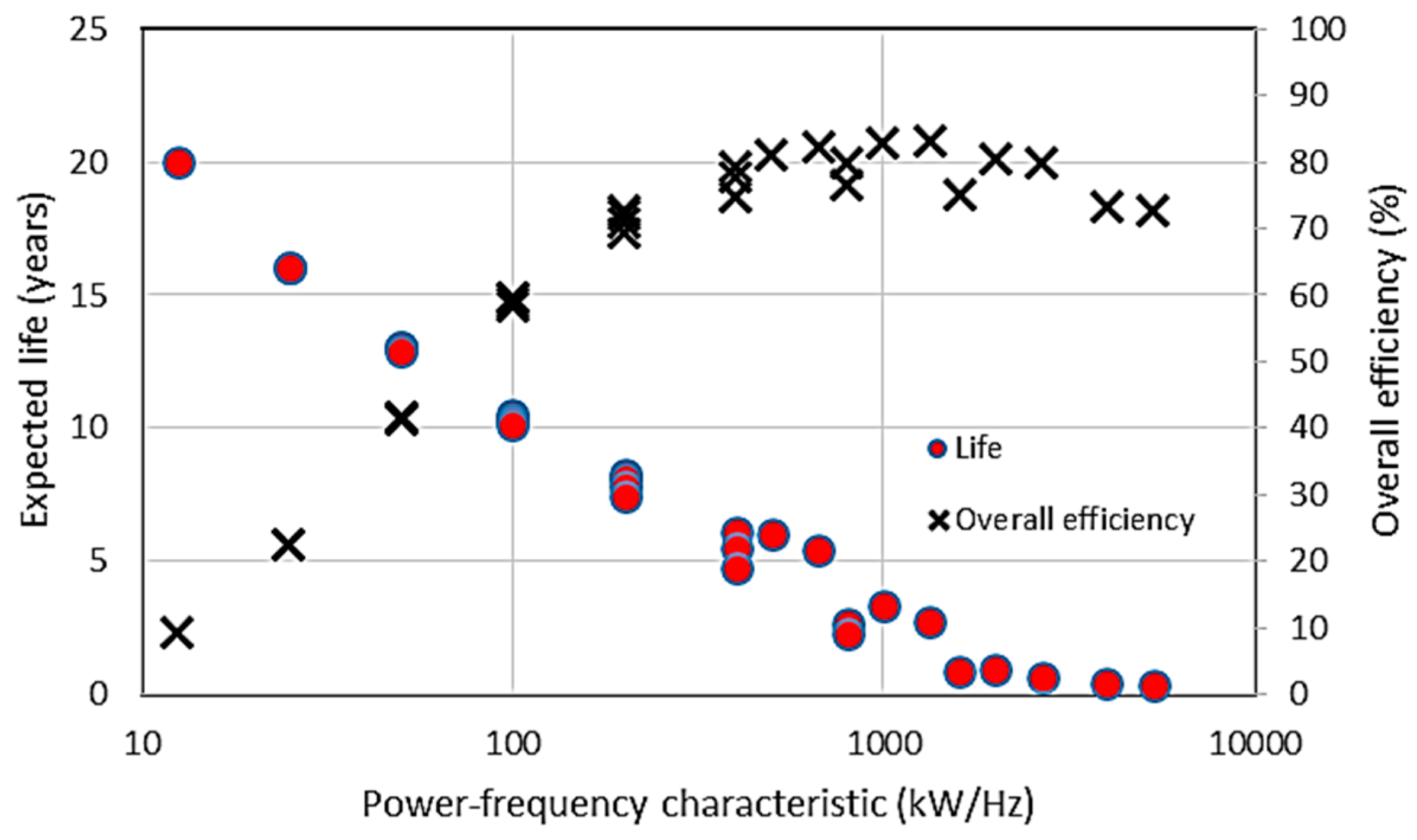
Figure 13 as a function of the equivalent power-frequency characteristic λ.
Figure 13 shows that combinations of droop and
C-rate yielding the same λ largely result in similar lifetimes and efficiencies, so that battery power-frequency characteristic could be taken as the actual design parameter for performing PFC with a BESS. As long as the system is linear and time-invariant, the same λ values lead to the same results. However, both the model and the control strategy (which includes dead band, recharge phase, temperature and SOC limits) are not linear, resulting in some differences.
Such differences are smaller when the battery is less stressed (i.e., at low λ values), and increase with increasing λ values. It should be pointed out that the longer BESS lifetimes predicted at low λ values could be offset by components having a shorter life than the battery itself, notably the electronic equipment.
To carry out an economic evaluation of the PFC application, applicable (i.e., national) rules of the electric energy market must be considered, assuming that a PFC market exists. Considering the different national approaches and the relative volatility of the regulatory framework for ancillary services, only general economic remarks can be made here.
Notably, given the short BESS lifetime under intensive cycling, the most favorable scenario would seem to be a capacity-based PFC market (especially in association to high
C-rate values), whereas operation in an energy-based PFC market, such as in Italy [
41], seems much less promising due to need for sustained cycling. Taking the capacity-based German PFC market as the reference market, some rough net present values (
NPV) calculations may be made for the Terna’s 1 MWh BESS. Since such a market remunerates primary control for each MW of reserve deployed when Δ
f = 200 mHz [
42,
43],
s = 0.4% is the droop value required in order to fully exploit the 1 MWh BESS for PFC (Equation (1)).
Table 8 reports PFC results obtained for
s = 0.4% and for different
C-rate values.
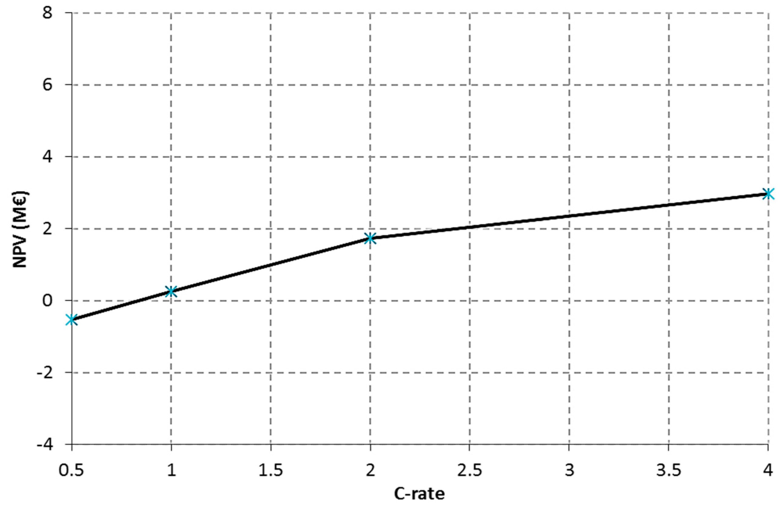
Figure 14 reports
NPVs, calculated for
s = 0.4%, as a function of
C-rate. A 3.6% capitalization factor and a 20-year BESS operation period have been considered. With reference to recent Terna BESS projects [
24,
44], battery cost has been set to 0.4 M€/MWh (if the battery life is shorter than 20 years, replacement cost is accounted as yearly economic losses equal to the ratio between battery cost and estimated battery life); fixed costs (civil works, MV switchgear, control system) have been set to 0.8 M€/MWh; PCS cost has been considered to be 0.2 M€/MW. The cost of losses, which are evaluated by means of the overall efficiency η
TOT, has been set at 140 €/MWh, whereas weekly revenues have been set to
Rw,unitary = 3000 €/MW/week, a typical value for the German market [
45]. For the same 1 MWh battery, consideration of different nominal
C-rates (namely 0.5C, 1C, 2C and 4C) leads to different unitary BESS active power capabilities (0.5 MW, 1 MW, 2 MW and 4 MW, respectively). As a consequence, the weekly revenues (which depends on BESS active power capability) linearly depend on
C-rates. The yearly incomes
Ry,tot have thus been evaluated as:
Due to the modular design of BESS [
24], this implies that the economic evaluation for a larger system could be simply carried out by scaling up the above-described implementation and its attendant costs and revenues.
7. Conclusions
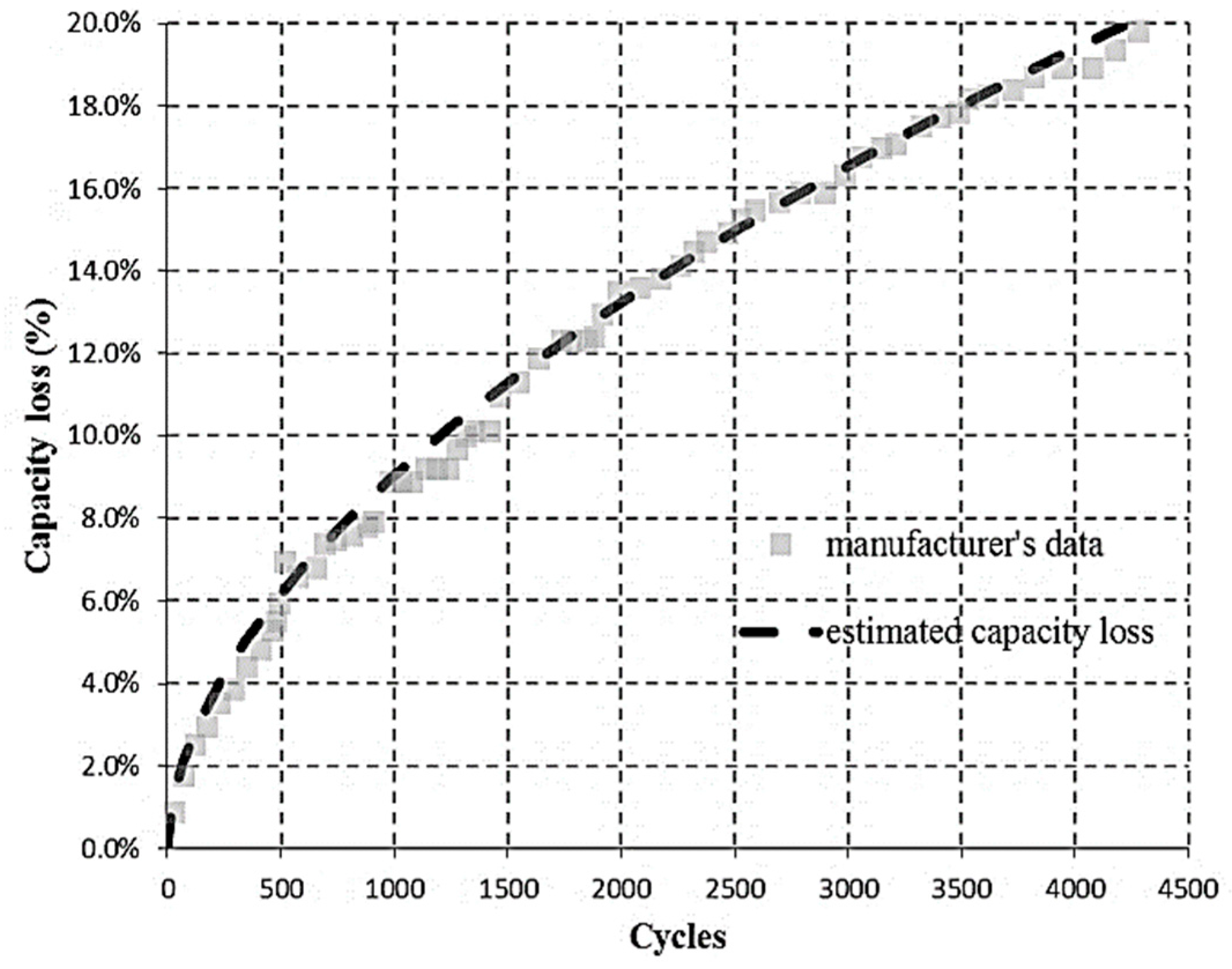
The paper studied the application of a LiFePO4 BESS to primary frequency control, in the ENTSO-E Continental Europe grid; technical data from Terna’s (the Italian TSO) experimental system has been used for defining BESS characteristics. BESS behavior has been simulated by the combination of an electrical-thermal circuit model with a life-cycle model predicting the capacity loss of the LiFePO4 battery due to charge-discharge cycles. The complete electrical-thermal-ageing model has been subsequently validated by comparisons both with experimental tests carried out by Terna and with manufacturer data. Lastly, numerical PFC simulations have been performed by using actual Italian (ENTSO-E continental system) frequency recordings and considering a conventional, proportional “governor” for the BESS, for a wide range of different droop/C-rate combinations.
The main result evidenced by the simulations is that high overall BESS efficiency and expected lifetime are conflicting requirements. High efficiency in PFC service is associated to C-rate/droop combinations yielding high values of the power-frequency characteristic λ, which naturally results in sustained cycling of the BESS that drastically shortens expected battery lifetime. As an example, for the simulated and tested 50 kW-50 kWh battery string the choice of λ = 200 kW/Hz (C-rate = 1C, 0.5% droop) results in an overall efficiency exceeding 72%, but the expected lifetime is about 8 years. For a given frequency profile, lower λ values (e.g., associated to the usual 4%–5% droop of conventional generators’ governors) result in less battery cycling and longer lifetimes, possibly approaching the conventional 20 years value, albeit with much lower efficiencies due to auxiliary losses.
The paper showed the technical feasibility of LiFePO4 BESS use in primary frequency control, evidencing that there is a significant trade-off between expected lifetime and overall efficiency, restricting the choice of operating parameters to a rather narrow band; in the studied system, lifetimes in excess of 10 years are actually associated to efficiencies below 60%, mainly because of BESS underutilization.
Besides the above reported technical issues, an economic evaluation would depend on the specific (national) rules of the PFC market, whether capacity-based or energy-based. Considering a capacity–based market, such as the German one, results show that high C-rate values (≥1C) seem to be more profitable.


