Article

Application of Model Predictive Control to BESS for Microgrid Control

Department of Electrical Engineering, Incheon National University, 12-1 Songdo-dong, Yeonsu-gu, Incheon 406-840, Korea
*
Author to whom correspondence should be addressed.
Energies 2015, 8(8), 8798-8813; https://doi.org/10.3390/en8088798
Submission received: 27 June 2015 / Revised: 5 August 2015 / Accepted: 5 August 2015 / Published: 19 August 2015
(This article belongs to the Special Issue Control of Energy Storage)

Abstract

:
Battery energy storage systems (BESSs) have been widely used for microgrid control. Generally, BESS control systems are based on proportional-integral (PI) control techniques with the outer and inner control loops based on PI regulators. Recently, model predictive control (MPC) has attracted attention for application to future energy processing and control systems because it can easily deal with multivariable cases, system constraints, and nonlinearities. This study considers the application of MPC-based BESSs to microgrid control. Two types of MPC are presented in this study: MPC based on predictive power control (PPC) and MPC based on PI control in the outer and predictive current control (PCC) in the inner control loops. In particular, the effective application of MPC for microgrids with multiple BESSs should be considered because of the differences in their control performance. In this study, microgrids with two BESSs based on two MPC techniques are considered as an example. The control performance of the MPC used for the control microgrid is compared to that of the PI control. The proposed control strategy is investigated through simulations using MATLAB/Simulink software. The simulation results show that the response time, power and voltage ripples, and frequency spectrum could be improved significantly by using MPC.

1. Introduction

Microgrids are becoming popular in distribution systems because they can improve the power quality and reliability of power supplies and reduce the environmental impact. Microgrid operation can be classified into two modes: grid-connected and islanded modes. In general, microgrids are comprised of distributed energy resources (DERs) including renewable energy sources, distributed energy storage systems (ESSs), and local loads [1,2,3]. However, the use of renewable energy sources such as wind and solar power in microgrids causes power flow variations owing to uncertainties in their power outputs. These variations should be reduced to meet power-quality requirements [4,5]. This study focuses on handling the problems that are introduced by wind power.
To compensate for fluctuations in wind power, various ESSs have been implemented in microgrids. Short-term ESSs such as superconducting magnetic energy storage (SMES) systems [6], electrical double-layer capacitors (EDLCs) [7], and flywheel energy storage systems (FESSs) [8,9,10] as well as long-term ESSs such as battery energy storage systems (BESSs) [11,12] are applied to microgrid control. ESSs can also be used to control the power flow at point of common coupling in the grid-connected mode as well as to regulate the frequency and voltage of a microgrid in the islanded mode. Among these ESSs, BESSs have been implemented widely owing to their versatility, high energy density, and efficiency. Moreover, their cost has decreased whereas their performance and lifetime has increased [13].
In practice, BESSs with high performance such as smooth and fast dynamic response during charging and discharging are required for microgrid control. This performance depends on the control performance of the power electronic converter. Proportional-integral (PI) control is a practical and popular control technique for BESS control systems. However, PI control might show unsatisfactory results for nonlinear and discontinuous systems [10]. Meanwhile, model predictive control (MPC) is considered an attractive alternative to promote the performance of future energy processing and control systems [14]. Predictive strategies are based on the inherent discrete nature of a power converter. Owing to the finite number of switching states of a power converter, all possible states are considered for predicting the system behavior. Then, each prediction is used to evaluate a cost function. Consequently, the switching state with the minimum cost function is selected and applied to the converter [15]. One of the advantages of an MPC is the easy inclusion of constraints and nonlinearities. Therefore, MPC has been widely applied to drive applications [15,16,17,18] and power converters such as active front-end rectifiers [19], matrix converters [20], and multilevel converters [21]. Recently, it has been applied to a bidirectional AC-DC converter for use in BESSs [22,23,24].
Only a few literatures were found on the application of MPC to microgrid control. Most existing studies focused on MPC for a distributed generator in a microgrid with voltage and/or power control [25,26,27]. A modified MPC method for voltage control of a BESS in the islanded mode operation of a microgrid was presented in [27]. However, this study did not deal with frequency control in the islanded mode operation of a microgrid. MPC based on PI control in the outer control loop and predictive current control (PCC) in the inner control loop for BESS was presented in [28]. Coordinated predictive control of a wind/battery microgrid system was proposed to maintain the system voltage and frequency by adjusting the output power of BESS. PCC was used to control the current in the inner control loop, whereas PI regulators were used to regulate the voltage and power in the outer control loop. Owing to the use of PI regulators in the outer control loop, the dynamic response time under such MPC techniques was similar to that under PI control techniques with outer and inner control loops using PI regulators.
Another MPC technique is based on predictive power control (PPC), in which the power is predicted and controlled directly. This MPC technique could be applied to microgrid control because it affords advantages such as fast dynamic response for power control; however, studies have not yet explored the application of the PPC-based MPC technique to microgrid control. Furthermore, this MPC technique can only be used for power control. To overcome this problem, PI regulators can be used in an additional control loop to control the frequency and voltage. Therefore, this MPC technique uses PI regulators in the outer control loop and PPC in the inner control loop. It is similar to previous MPC techniques in which PI control is used in the outer control loop and PCC is used in the inner control loop. However, an MPC technique based on PI and PPC requires more computation time than does one based on PI and PCC, owing to the predicting powers in the inner PPC control loop. Therefore, in a microgrid with a single BESS, MPC based on PI and PCC is a suitable alternative for microgrid control. Another approach to overcome this limitation of the MPC control technique is to use a droop control scheme. Thus, a PPC-based MPC technique can be applied to microgrids consisting of multiple BESSs with different functionalities. This study deals with the effective application of an MPC technique to a microgrid with two BESSs as an example of multiple BESSs in a microgrid.
This study discusses the effective application of two MPC techniques to BESSs for microgrid control based on the characteristics of the MPC techniques as well as the functionalities of BESSs. One BESS is based on PI control in the outer and PCC in the inner control loops (PI (outer) + PCC (inner)); it is used for smoothing wind power fluctuations both in the grid-connected and the islanded modes. The other BESS is based on PPC (one loop); it controls the tie-line powers at the point of common coupling in the grid-connected mode and the frequency in the islanded mode. Additionally, to reduce the power losses of converters, the reduction of the switching frequency of the converter is considered an additional control variable in the MPC algorithm. The control performances of the two types of MPC techniques are compared to the PI control technique using PI regulators in the outer and inner control loops (PI (outer) + PI (inner)). The tuning of PI regulator parameters must be taken into account to effectively compare the control performance of MPC techniques to the PI control technique. Several tuning techniques have been used to select the PI regulator parameters. In this study, the tuning technique provided by MATLAB/Simulink software is used. The efficacy of the proposed control system is verified via simulations in the MATLAB/Simulink environment.
The remainder of this paper is organized as follows. Section 2 introduces the discrete-time model of the converter for prediction and MPC algorithms. Two types of MPC techniques are introduced in this section. Section 3 describes the microgrid system used to test the performance of the proposed control strategies. Section 4 presents a comparison of the MPC and PI control techniques and the considerations for the effective application of MPC-based BESSs to microgrid control. Section 5 presents the simulation results for microgrid control in the grid-connected and islanded modes. The performances of the MPC techniques are compared to those of the PI control technique. Finally, Section 6 summarizes the main conclusions of this study.

2. MPC for BESS

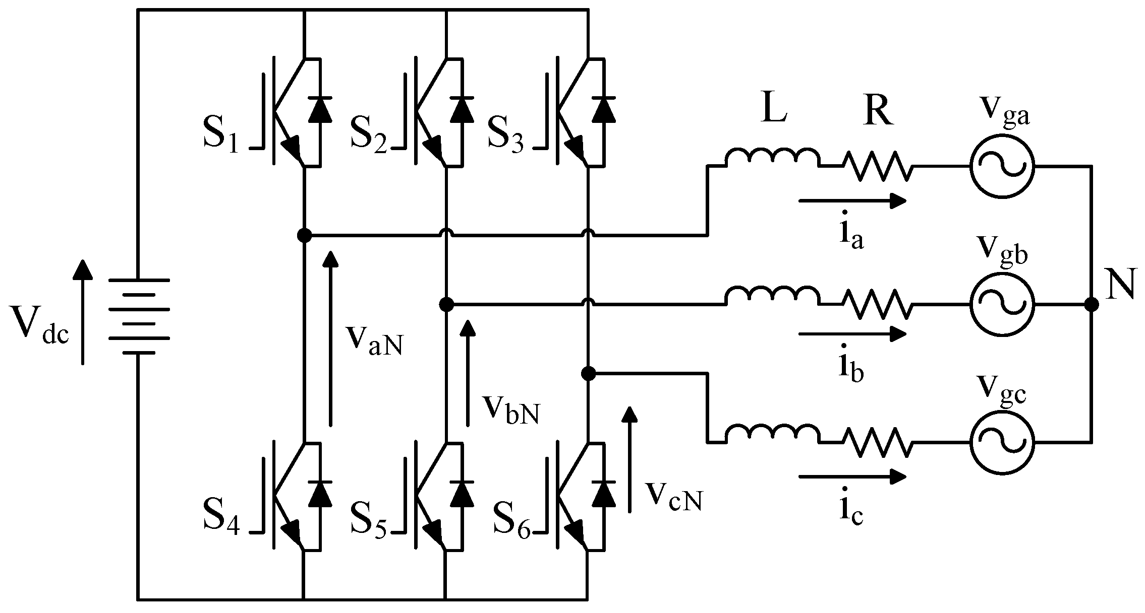
2.1. Discrete-Time Model of Converter

The predicted variables of BESS are determined based on the discrete-time model of the converter. In this study, the BESS uses a two-level voltage source converter (VSC) converter, shown in Figure 1, connected to the three-phase AC power supply voltage vg through filter inductance L and resistance R. The equations for each phase are given by Equations (1)–(3):
v a N = L d i a d t + R i a + v g a
v b N = L d i b d t + R i b + v g b
v c N = L d i c d t + R i c + v g c
Figure 1. Configuration of BESS.
Energies 08 08798 g001
These equations can be represented by the space-vector equations given in Equation (4).
2 3 ( v a N + a v b N + a 2 v c N ) = L d d t ( 2 3 ( i a + a i b + a 2 i c ) ) + R ( 2 3 ( i a + a i b + a 2 i c ) ) + 2 3 ( v g a + a v g b + a 2 v g c )
where a = e j 2 π / 3 .
Equation (4) can be simplified by considering the following definitions.
v = 2 3 ( v a N + a v b N + a 2 v c N )
i = 2 3 ( i a + a i b + a 2 i c )
v g = 2 3 ( v g a + a v g b + a 2 v g c )
The voltage v in Equation (5) is determined by the switching states of the converter and the DC link voltage ( V D C ), as given in Equation (8).
v = 2 3 V D C ( S a + a S b + a 2 S c )
Where the switching signals Sa, Sb, and Sc are defined as follows:
S a = { 1   if   S 1   on   and   S 4   off 0   if   S 1   off   and   S 4   on
S b = { 1   if   S 2   on   and   S 5   off 0   if   S 2   off   and   S 5   on
S c = { 1   if   S 3   on   and   S 6   off 0   if   S 3   off   and   S 6   on
The combination of Sa, Sb, and Sc creates eight switching states and eight voltage vectors, as shown in Table 1.
Table 1. Switching states and voltage vectors [29].
xSaSbScVoltage vectors
1000v0 = 0
2100 v 1 = 2 3 V d c
3110 v 2 = 1 3 V d c + j 3 3 V d c
4010 v 3 = 1 3 V d c + j 3 3 V d c
5011 v 4 = 2 3 V d c
6001 v 5 = 1 3 V d c j 3 3 V d c
7011 v 6 = 1 3 V d c j 3 3 V d c
8111v7 = 0
Substituting Equations (5)–(7) in Equation (4), we get
v = L d i d t + R i + v g
From Equation (12), the discrete-time model of the converter is determined by approximating the derivative load current d i / d t in terms of a forward Euler approximation, as shown in Equation (13).
d i d t i ( k + 1 ) i ( k ) T s
By substituting Equation (13) in Equation (12), the future current at the sampling instant k + 1 is represented as
i p ( k + 1 ) = ( 1 R T s L ) i ( k ) + T s L ( v ( k ) v g ( k ) )
where i(k) and vg(k) are the three-phase current and voltage of the BESS measured at sampling instant k, respectively; v(k) is the voltage vector according to the eight switching states of the converter; and Ts is the sampling time.
Based on the measured voltage and current of BESS at sampling instant k, the variables at sampling instant k + 1 are predicted as given in Equation (14). For a small sampling time (Ts), the predicted grid voltage at sampling instant k + 1 can be assumed equal to the measured grid voltage at the kth sampling instant (vg(k + 1) = vg(k)) owing to the fundamental grid frequency [29]. As a result, the predicted instantaneous real and reactive powers can be expressed as follows:
P p ( k + 1 ) = 1.5 R e { i ¯ p ( k + 1 ) v g m ( k ) }
Q p ( k + 1 ) = 1.5 I m { i ¯ p ( k + 1 ) v g m ( k ) }
where i p ( k + 1 ) is the complex conjugate of the predicted current vector i p ( k + 1 ) .
Equations (14)−(16) show that the predictive current and power highly rely on system model, converter, and filter parameters. Any change in the model parameters can provide inaccuracy in the predictive variables. Reference [29] shown that the current or power ripple could be affected by the parameter variations, whereas the dynamic response was almost unchanged. In case of extreme variations in the model parameters, an online parameter estimation algorithm should be included in the MPC strategy [30,31]. However, MPC can effectively handle the small change in inductive filter parameters. The comparison between MPC with and without the online filter estimation was presented in [29,32]. The major errors were observed at low values of the filter parameters. In addition, only a small difference was observed at high values of the filter parameters. In this study, a high value of the filter parameter is chosen to avoid the major errors by filter parameter variations. Thus, the model parameters is assumed unchanged during simulation for the sake of simplicity.

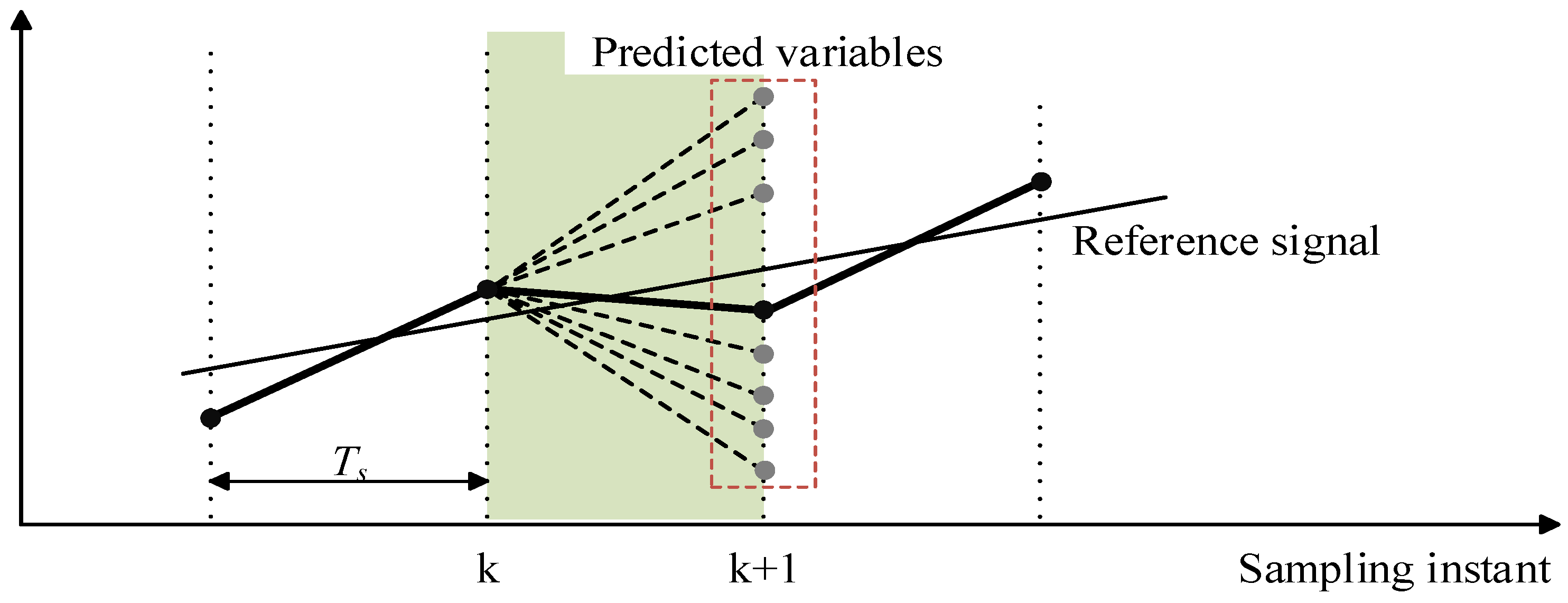
2.2. Principle of MPC

MPC is based on the inherent discrete nature of a power converter, which has a finite number of switching states. All possibilities of variables (current or real/reactive powers) of the converter according to switching states can be predicted. The predicted variables are compared to the reference control signal, and the predicted variable that is closest to the reference control signal is chosen as shown in Figure 2. Then, the switching state related to this predicted variable is applied to control the converter.
Figure 2. Principle of MPC.
Energies 08 08798 g002
Figure 3 shows two types of MPC techniques applied for BESSs: MPC based on PI control in the outer and PCC in the inner control loops (Figure 3a) and MPC based on PPC (Figure 3b). As shown in Figure 3a, PI control in the outer control loop is used to regulate the real/reactive powers as well as voltage of the microgrid. The reference current obtained by the outer control loop is used for the inner PCC control loop based on Equation (14). As shown in Figure 3b, in comparison, PPC based on Equations (15) and (16) can control real/reactive powers directly. To control the frequency of the microgrid, the frequency droop control scheme is suitable for a BESSs control system. However, conventional droop control can cause a steady-state error [33]. Thus, this study proposes an improved droop control scheme in which the steady-state error is removed by a new feedback signal through the PI regulator [9].
The objective of the MPC scheme is to minimize the error between the reference values and the measured values. This can be achieved by introducing a cost function g C for PCC and g S for PPC, as shown in the following equations.
g C = | i α * ( k + 1 ) i α p ( k + 1 ) | 2 + | i β * ( k + 1 ) i β p ( k + 1 ) | 2 + λ C n
g S = | P * ( k + 1 ) P p ( k + 1 ) | 2 + | Q * ( k + 1 ) Q p ( k + 1 ) | 2 + λ S n
where i α * ( k + 1 ) and i β * ( k + 1 ) are the real and imaginary parts of the reference current, i α p ( k + 1 ) and i β p ( k + 1 ) are the real and imaginary parts of the predicted current vectors i p ( k + 1 ) according to Equation (14), P * ( k + 1 ) and Q * ( k + 1 ) are the real and reactive reference powers, P p ( k + 1 ) and Q p ( k + 1 ) are the predicted real and reactive powers according to Equations (15) and (16), λ C n and λ S n represent the reduction of switching frequency of the converter where n is the number of switches that change when the switching states S = ( S a ,   S b ,   S c ) are applied, and λ C and λ S are the weighting factor for PCC and PPC, respectively.
The cost functions g C and g S have two terms with different goals. The primary goal is the current control in case of g C or power control in case of g S , which must be achieved to provide a proper system behavior. The secondary goal is the reduction of switching frequency ( λ C n and λ S n ) in both cost functions. The importance of second term corresponds to the weighting factors λ C and λ S that can impose a trade-off with the primary control objective. The algorithm to adjust the weighting factors proposed in [29] is used in this study. Total harmonic distortion (THD) is used to estimate the trade-off between the primary and secondary goals.
The switching frequency of the converter depends on the change in the switching state, which can be only one or zero. Therefore, the number of switches that change from S ( k 1 ) to S ( k ) is defined as given in Equation (19):
n   =   | S a ( k ) S a ( k 1 ) | + | S b ( k ) S b ( k 1 ) | + | S c ( k ) S c ( k 1 ) |
Figure 3. MPC block diagrams: (a) MPC based on PI control in the outer and PCC in the inner control loops; (b) MPC based on PPC.
Energies 08 08798 g003
The control strategy of MPC techniques involves the following four steps:
(1)
The three-phase current and voltage of the BESS are measured, and the values of reference signals are obtained from the outer control loop.
(2)
The discrete-time model of the converter is used to predict the values of current or real/reactive powers in the next sampling interval (k + 1) for each voltage vector according to Equations (14)–(16).
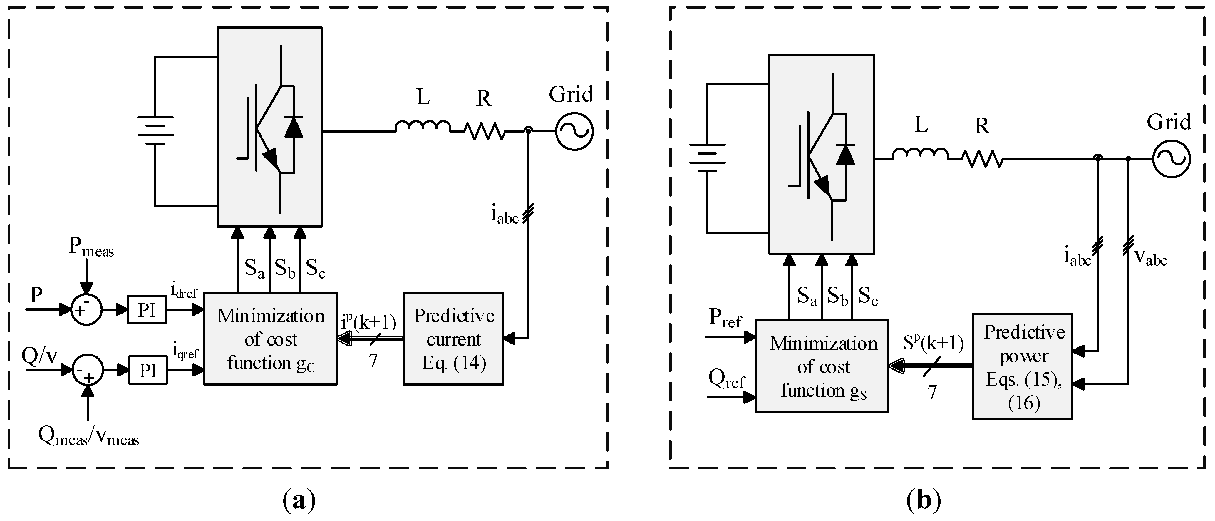
(3)
The cost function g C or g S based on Equations (17) and (18) is used to compute the errors between the reference and the predicted current or real/reactive powers for each voltage vector.
(4)
The minimum value of the cost function gives the minimum error between the reference and the measured signals. The voltage vector with respect to the minimum cost function is selected, and the corresponding switching state signals are generated to apply to the converter.
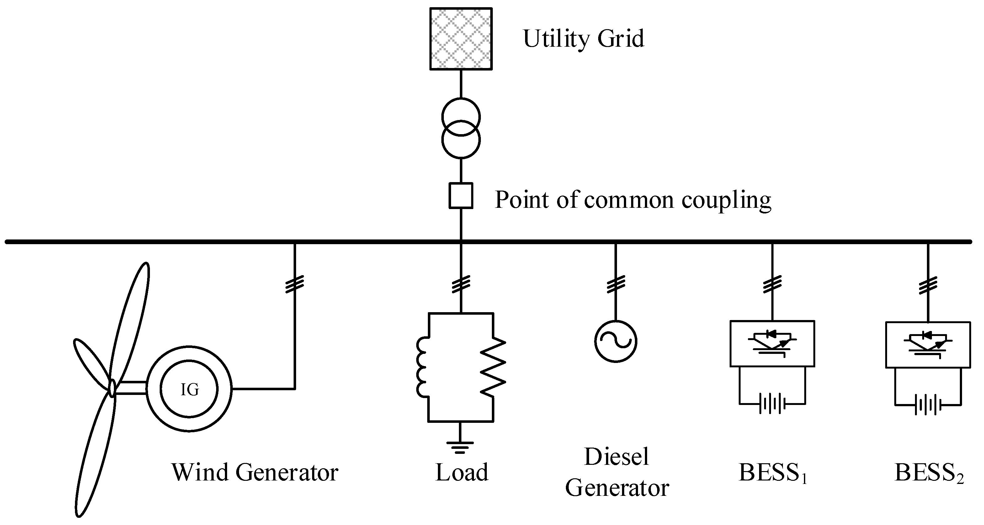
3. Test Microgrid

The test microgrid system (Figure 4) used in this study includes several components: A diesel generator, a consumer load, a wind generator, and two BESSs. Table 2 shows the parameters of the test microgrid system. In this study, the fixed-speed wind energy conversion system (WECS), a type of WECS [34], is used for simplicity. Two BESSs with different control strategies according to the operation mode of the microgrid, as shown in Table 3, are used. In the grid-connected mode, the voltage and frequency of the microgrid is set by the utility grid. Therefore, the main function of the BESS is to control the real and reactive powers. On the other hand, in the islanded mode, the microgrid is disconnected from the utility grid and controls its own frequency and voltage.
Figure 4. Configuration of microgrid.
Energies 08 08798 g004
Table 2. Parameters of test microgrid.
ComponentsRating
Wind generator150 kVA
BESS1450 kWh
BESS2200 kWh
Load500 kW; 100 kVAR
Diesel generator500 kVA
Mean wind speed9 m/s
System frequency60 Hz
Transformer700 kVA; 6.6 kV/380 V
Table 3. Control strategies of BESSs.
Operation modesBESS1BESS2
Grid-connectedTie-line powers at point of common couplingSmoothing wind power
IslandedFrequency controlSmoothing wind power
Reactive power at point of common couplingVoltage control

4. Control Performance of MPC Techniques

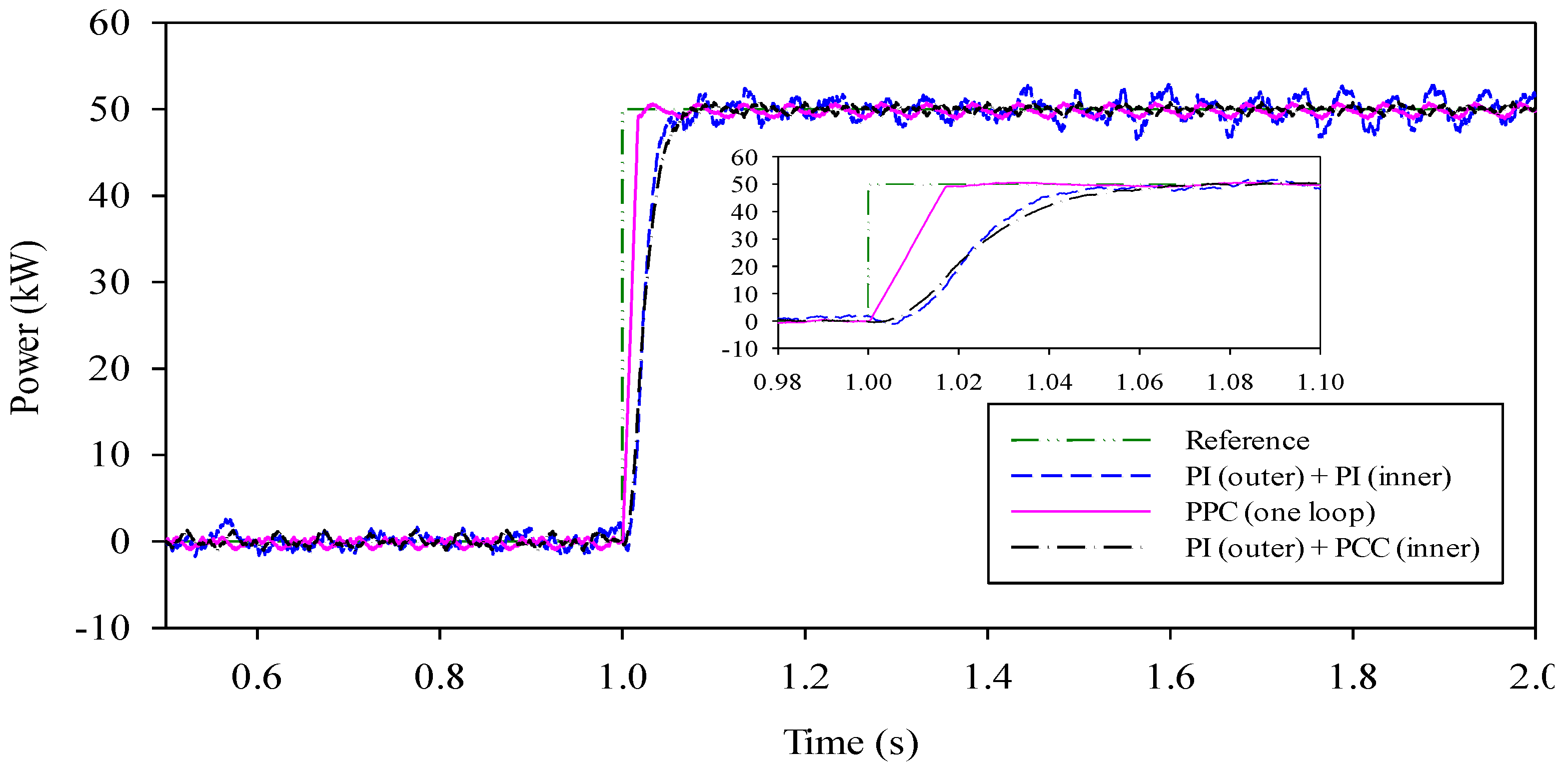
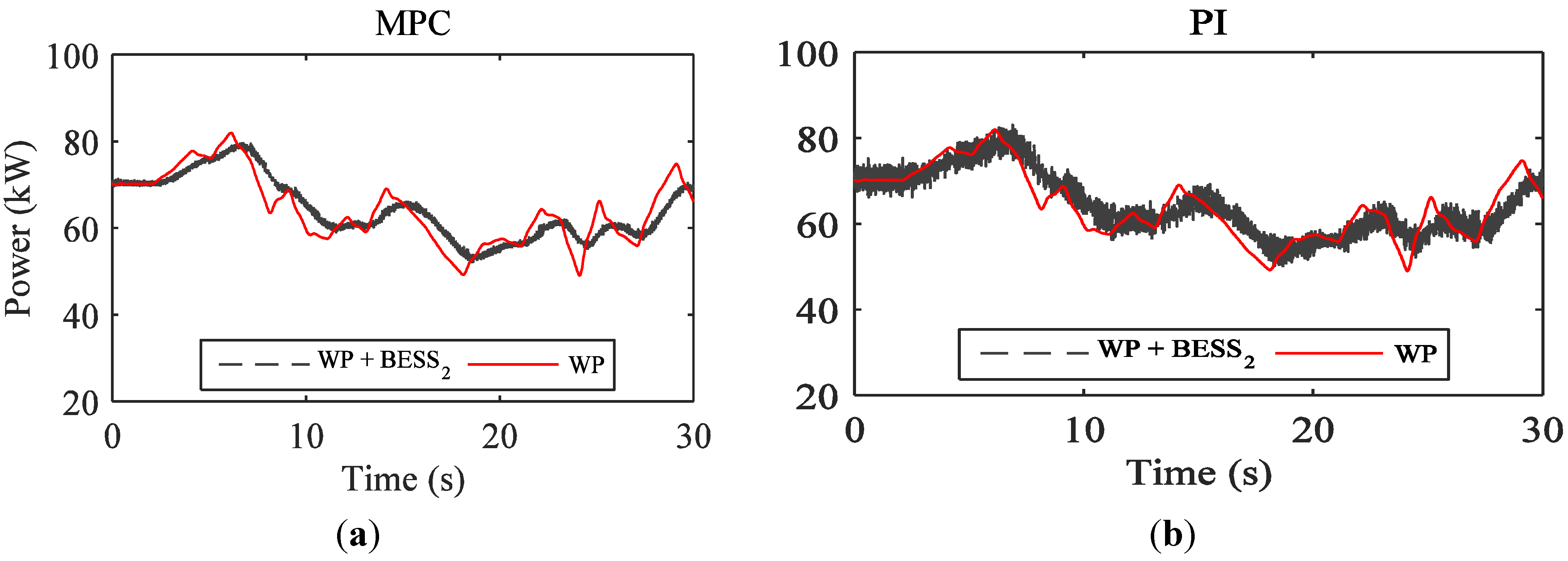
4.1. Comparison of Control Performance of MPC and PI Control Techniques

The control performances of two MPC techniques according to the change in real power are compared to that of the PI control technique proposed in [35]. Tuning the PI parameters is an important factor for comparison. Several functions as well as linear analysis tools provided by MATLAB/Simulink are used for tuning. First, the function “getlinio” is used to obtain the linearized input/output of the plant. The linear approximation of the plant is estimated based on the linearized input/output by using the “linearize” function. Then, the linear analysis tool in Simulink is used to estimate the frequency response of a plant based on the linear approximation of the plant. Finally, the PID tuner in Simulink is used to automatically tune the PI parameters based on the frequency response estimation.
Figure 5 shows the simulation results of three types of control techniques. The real power changes from 0 to 50 kW at 1.0 s. The response of the PPC technique is clearly much quicker than that of other techniques. In the case of MPC based on PI in the outer and PCC in the inner control loops and PI control technique using PI regulators in the outer and inner control loops, the dynamic response is similar owing to the action of the PI controller in the outer control loop. Both MPC technique based on PI and PCC and PI technique show good reference tracking under the steady-state condition. However, the power ripple obtained by MPC technique is smaller than that obtained by PI control technique owing to PCC in the inner control loop in MPC technique. Figure 5 shows that MPC techniques can significantly improve the performance of a control system for BESSs in terms of the response time and power ripple.
Figure 5. Response of different control techniques for change in reference power.
Energies 08 08798 g005

4.2. Effective Application of MPC Techniques to Microgrid Control

Table 4 shows the characteristics of the MPC and PI control techniques. Among these two MPC techniques, the PPC technique shows the best control performance; however, it can only be used for controlling the power. On the other hand, the MPC technique based on PI in outer and PCC in inner control loops is more flexible owing to the use of a PI regulator in the outer control loop; this technique can be used to control the power, frequency, and voltage. The ripple in case of both MPC techniques is smaller than that in case of the PI control technique.
Table 4. Characteristics of MPC and PI control techniques.
CharacteristicsPI (outer) + PI (inner)PI (outer) + PCC (inner)PPC (one loop)
Ability to controlP/Q, f/vP/Q, f/vP/Q
Response timeLongLongShort
RippleLargeSmallSmall
In this study, two BESSs with different functionalities are proposed to control the microgrid, as shown in Table 3. BESS1 is used to control the power at the point of common coupling and the frequency in the islanded mode, in which case fast dynamic response under disturbances is required for the control system. Therefore, PPC-based MPC is suitable for application to BESS1 because its control performance shows the shortest response time compared to other cases. Furthermore, BESS2 is used for handling fluctuations in wind power in both grid-connected and islanded modes. Thus, the control performance of the MPC technique based on PI control in the outer control loop and PCC control in the inner control loop is suitable for BESS2 owing to gradual fluctuations in wind power. The microgrid voltage is controlled by BESS2 and the frequency, by BEES1 and BESS2 through the improved frequency droop control scheme.

5. Simulation Results

5.1. Control Microgrid in Grid-Connected Mode

BESSs can operate in the charging or discharging mode. Therefore, they can reduce the fluctuations in wind power through effective compensation. Figure 6 shows the action of BESS2 in terms of smoothing the wind power. In the case of BESS2, the MPC technique based on PI control in the outer control loop and PCC in the inner current control loop is applied as the control system. This figure shows that the wind power fluctuations can be reduced significantly by effectively charging or discharging BESS2. Both the MPC and the PI control techniques show good results from the viewpoint of smoothing the wind power. However, the power ripple in case of the MPC technique is much smaller than that in case of the PI control technique.
On the other hand, BESS1 based on the PPC technique controls the power at the point of common coupling. In this study, it is assumed that the real power at the point of common coupling is maintained at zero. Figure 7 shows the simulation result. At 10 s, an additional load of 100 kW is connected to the microgrid. Therefore, BESS1 increases its real power to maintain the power at zero. The subfigure of Figure 7 shows that the response of the MPC technique is slightly quicker than that of the PI control technique. Additionally, the ripples of the BESS power when using the MPC technique is smaller than that of PI control technique. Both the MPC and the PI control techniques show good performance for controlling the power at the point of common coupling.
Figure 6. Smoothened wind power: (a) MPC technique; (b) PI technique.
Energies 08 08798 g006
Figure 7. Real power at point of common coupling and real power of BESS1.
Energies 08 08798 g007

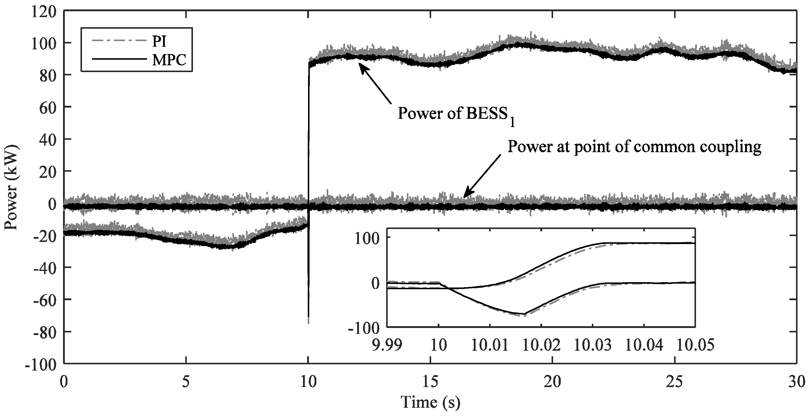
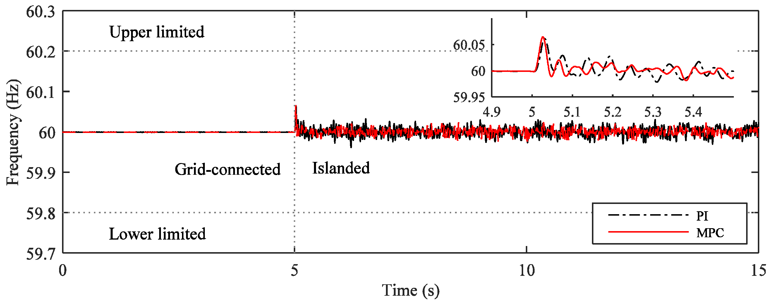
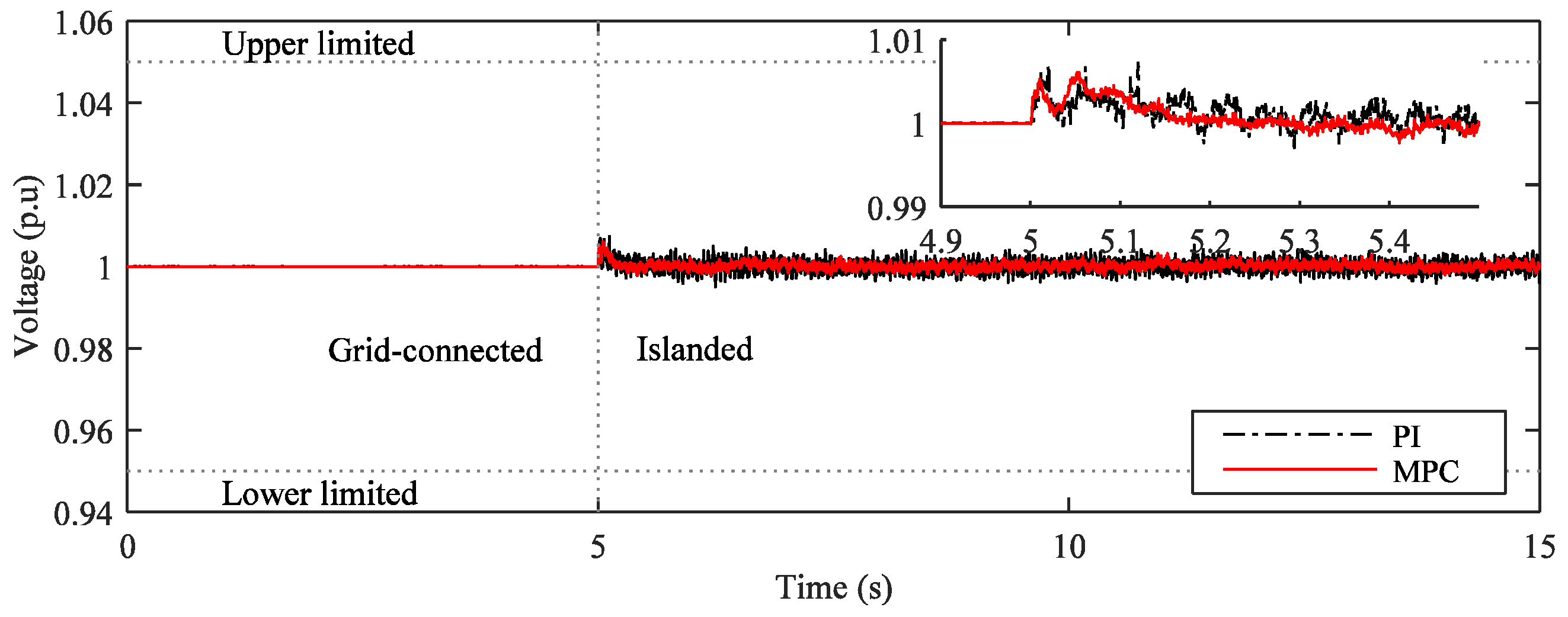
5.2. Control Microgrid in Islanded Mode

In the islanded mode, the microgrid frequency is controlled by BESS1, and the microgrid voltage is controlled by BESS2. Figure 8 and Figure 9 respectively show the frequency and voltage of the microgrid. Both the MPC and the PI control techniques can stably control the frequency and voltage of the microgrid. However, as shown in Figure 8, the frequency response under the MPC technique is quicker than that under the PI control technique. Moreover, Figure 9 shows the microgrid voltage. Obviously, the performance of the MPC techniques is much better than that of the PI control technique. The voltage ripple in the case of the MPC technique is much smaller than that in the case of the PI control technique.
Figure 8. Frequency of microgrid system.
Energies 08 08798 g008
Figure 9. Voltage of microgrid system.
Energies 08 08798 g009
Additionally, the output voltage spectra generated by the converter is one of the important factors. Figure 10 shows a comparison of the voltage spectra of the MPC and PI control techniques. As shown in Figure 10b, the frequency spectrum generated using the PI control technique is concentrated around the carrier frequency owing to PWM. For comparison, Figure 10a shows the frequency spectrum obtained by MPC. The reduction of the switching frequency of the converter is implemented in the cost function of MPC as a secondary control objective to reduce the power losses of converters. Figure 10 shows that the average switching frequency ( f s ) obtained by MPC is slightly lower than that obtained by the PI control technique. Moreover, the MPC technique shows significantly lower THD than the PI control technique.
Figure 10. Load voltage spectrum and THD: (a) MPC technique; (b) PI technique.
Energies 08 08798 g010

6. Conclusions

This study discusses the effective application of two types of MPC techniques to BESSs for microgrid control: MPC based on PPC and MPC based on PI control in the outer control loop and PCC in the inner current control loop. In addition, PI control using a PI regulator in the outer and inner control loops for BESS was compared to these two types of MPC techniques. A reduction switching frequency is implemented in the cost function to reduce the power losses of converters. The simulation results show that the response time, power ripples, and frequency spectrum could be improved significantly by using MPC techniques. Both the average switching frequency and the THD obtained by using MPC techniques were lower than those obtained by using PI control. Using MPC based on PI control in the outer and PCC in the inner control loops did not improve the response time under power changing compared to PI control; however, it could significantly improve the power and voltage ripples under the steady-state condition. Moreover, using PPC-based MPC could reduce the response time under power changing compared to other control techniques. Therefore, in microgrids with multiple BESSs, the PPC-based MPC technique should be applied for BESSs that control the power at the point of common coupling and the frequency of the microgrid, and an MPC technique based on PI in the outer control loop and PCC in the inner control loop should be applied for BESSs that play the role of smoothing wind power fluctuations. Besides, in case of microgrids with a BESS, PCC-based MPC technique should be a suitable alternative for the BESS owing to its flexible characteristic. MPC technique is easy to implement and it can eliminate the tuning controller parameters effort that has to be done in the PI technique. Furthermore, various control objectives can be included in the MPC strategies.
In the future, we plan to include additional control variables such as considering the state of charge of the battery and coordination control of multiple ESSs in the MPC algorithm.

Acknowledgments

This work was supported by the Power Generation & Electricity Delivery Core Technology Program of the Korea Institute of Energy Technology Evaluation and Planning (KETEP), granted financial resource from the Ministry of Trade, Industry & Energy, Republic of Korea. (No. 20141020402350).

Author Contributions

The paper was a collaborative effort between the authors. The authors contributed collectively to the theoretical analysis, modeling, simulation, and manuscript preparation.

Conflicts of Interest

The authors declare no conflict of interest.

References

  1. Mahmoud, M.S.; Hussain, S.A.; Abido, M.A. Modeling and control of microgrid: An overview. J. Frankl. Inst. 2014, 351, 2822–2859. [Google Scholar] [CrossRef]
  2. Hatziargyriou, N.D. Microgrids. IEEE Power Energy 2008, 6, 26–29. [Google Scholar] [CrossRef]
  3. Olivares, D.E.; Mehrizi-Sani, A.; Etemadi, A.H.; Canizares, C.A.; Iravani, R.; Kazerani, M.; Hajimiragha, A.H.; Gomis-Bellmunt, O.; Saeedifard, M.; Palma-Behnke, R.; et al. Trends in microgrid control. IEEE Trans. Smart Grid 2014, 5, 1905–1919. [Google Scholar] [CrossRef]
  4. Kim, H.-M.; Lim, Y.; Kinoshita, T. An intelligent multiagent system for autonomous microgrid operation. Energies 2012, 5, 3347–3362. [Google Scholar] [CrossRef]
  5. Kim, H.-M.; Kinoshita, T. A multiagent system for microgrid operation in the grid-interconnected mode. J. Electr. Eng. Technol. 2010, 2, 246–254. [Google Scholar] [CrossRef]
  6. Molina, M.G.; Mercado, P.E. Power flow stabilization and control of microgrid with wind generation by superconducting magnetic energy storage. IEEE Trans. Power Electron. 2011, 26, 910–922. [Google Scholar] [CrossRef]
  7. Inthamoussou, F.A.; Pegueroles-Queralt, J.; Bianchi, F.D. Control of a supercapacitor energy storage system for microgrid applications. IEEE Trans. Energy Conver. 2013, 28, 690–697. [Google Scholar] [CrossRef]
  8. Islam, F.; Al-Durra, A.; Muyeen, S.M. Smoothing of wind farm output by prediction and supervisory-control-unit-based FESS. IEEE Trans. Sustain. Energy 2013, 4, 925–933. [Google Scholar] [CrossRef]
  9. Nguyen, T.-T.; Yoo, H.-J.; Kim, H.-M. A flywheel energy storage system based on a doubly fed induction machine and battery for microgrid control. Energies 2015, 8, 5074–5089. [Google Scholar] [CrossRef]
  10. Chang, X.; Li, Y.; Zhang, W.; Wang, N.; Xue, W. Active disturbance rejection control for a flywheel energy storage system. IEEE Trans. Ind. Electron. 2015, 62, 991–1001. [Google Scholar] [CrossRef]
  11. Li, X. Fuzzy adaptive kalman filter for wind power output smoothing with battery energy storage system. IET Renew. Power Gener. 2012, 6, 340–347. [Google Scholar] [CrossRef]
  12. Li, X.; Hui, D.; Lai, X. Battery energy storage station (BESS)-based smoothing control of photovoltaic (PV) and wind power generation fluctuations. IEEE Trans. Sustain. Energy 2013, 4, 464–476. [Google Scholar] [CrossRef]
  13. Lawder, M.T.; Suthar, B.; Northrop, P.W.C.; De, S.; Hoff, C.M.; Leitermann, O.; Crow, M.L.; Santhanagopalan, S.; Subramanian, V.R. Battery energy storage system (BESS) and battery management system (BMS) for grid-scale applications. Proc. IEEE 2014, 102, 1014–1030. [Google Scholar] [CrossRef]
  14. Duran, M.J.; Prieto, J.; Barrero, F.; Toral, S. Predictive current control of dual three-phase drives using restraned search techiniques. IEEE Trans. Ind. Electron. 2011, 58, 3253–3263. [Google Scholar] [CrossRef]
  15. Kouro, S.; Cortés, P.; Vargas, R.; Ammann, U.; Rodríguez, J. Model predictive control—A Simple and powerful method to control power converter. IEEE Trans. Ind. Electron. 2009, 56, 1826–1838. [Google Scholar] [CrossRef]
  16. Miranda, H.; Cortés, P.; Yuz, J.I.; Rodríguez, J. Predictive Torque control of induction machines based on state-space models. IEEE Trans. Ind. Electron. 2009, 56, 1916–1924. [Google Scholar] [CrossRef]
  17. Morel, F.; Xuefang, L.S.; Retif, J.M.; Allard, B.; Buttay, C. A comparative study of predictive current control schemes for a permanent-magnet synchronous machine drive. IEEE Trans. Ind. Electron. 2009, 56, 2715–2728. [Google Scholar] [CrossRef]
  18. Bolognani, S.; Peretti, L.; Zigliotto, M. Design and implementation of model predictive control for electrical motor drives. IEEE Trans. Ind. Electron. 2009, 56, 1925–1936. [Google Scholar] [CrossRef]
  19. Cortés, P.; Rodríguez, J.; Antoniewicz, P.; Kazmierkowski, M. Direct power control of an AFE using predictive control. IEEE Trans. Power Electron. 2008, 23, 2516–2523. [Google Scholar] [CrossRef]
  20. Vargas, R.; Rodríguez, J.; Ammann, U.; Wheeler, P.W. Predictive current control of an induction machine fed by a matrix converter with reactive power control. IEEE Trans. Ind. Electron. 2008, 55, 4362–4371. [Google Scholar] [CrossRef]
  21. Abad, G.; Rodriguez, M.A.; Poza, J. Three-level NPC converter based predictive direct power control of the doubly fed induction machine at low constant switching frequency. IEEE Trans. Ind. Electron. 2008, 55, 4417–4429. [Google Scholar] [CrossRef]
  22. Torreglosa, J.P.; Garcia, P.; Femadez, L.M.; Jurado, F. Predictive control for the energy management of a fuel-cell-battery-supercapacitor tramway. IEEE Trans. Ind. Electron. 2014, 10, 276–285. [Google Scholar] [CrossRef]
  23. Hredzak, B.; Agelidis, V.G.; Jang, M. A model predictive control system for a hybrid battery-ultracapacitor power source. IEEE Trans. Power Electron. 2014, 29, 1469–1479. [Google Scholar] [CrossRef]
  24. Akter, M.P.; Mekhilef, S.; Tan, N.M.L.; Akagi, H. Model predictive control of bidirectional AC-DC converter for energy storage system. J. Electr. Eng. Technol. 2015, 10, 165–175. [Google Scholar] [CrossRef]
  25. John, T.; Wang, Y.; Tan, K.T.; So, P.L. Model predictive control of distributed generation inverter in a microgrid. In Proceedings of the 2014 IEEE Innovative Smart Grid Technologies (ISGT Asia), Kuala Lumpur, Malaysia, 20–23 May 2014; pp. 657–662.
  26. Jafari, H.; Mahmodi, M.; Rastegar, H. Frequency control of micro-grid in autonomous mode using model predictive control. In Proceedings of the 2012 IEEE Iranian Conference on Smart Grids (ICSG), Tehran, Iran, 24–25 May 2012; pp. 1–5.
  27. Naeiji, N.; Hamzeh, M.; Rahimi Kian, A. A modified model predictive control method for voltage control of an inverter in islanded microgrids. In Proceedings of the 2015 IEEE Power Electronics, Drives Systems & Technologies Conference (PEDSTC), Tehran, Iran, 3–4 February 2015; pp. 555–560.
  28. Han, J.; Solanki, S.K.; Solanki, J. Coordinated predictive control of a wind-battery microgrid system. IEEE J. Emerg. Sel. Top. Power Electron. 2013, 1, 296–305. [Google Scholar] [CrossRef]
  29. Rodríguez, J.; Cortés, P. Predictive Control of Power Converter and Electrical Drives; John Wiley & Sons: West Sussex, UK, 2012. [Google Scholar]
  30. Xia, C.; Wang, M.; Song, Z.; Liu, T. Robust model predictive current control of three-phase voltage source PWM rectifier with online disturbance observation. IEEE Trans. Ind. Informat. 2012, 8, 459–471. [Google Scholar] [CrossRef]
  31. Antoniewicz, P.; Kazmierkowski, M.P. Virtual-flux-based predictive direct power control of AC/DC converters with online inductance estimation. IEEE Trans. Ind. Electron. 2008, 55, 4381–4390. [Google Scholar] [CrossRef]
  32. Rivera, M.; Yaramasu, V.; Rodriguez, J.; Wu, B. Model predictive current control of two-level four-leg inverters—Part II: Experimental implementation and validation. IEEE Trans. Power Electron. 2013, 28, 3469–3478. [Google Scholar] [CrossRef]
  33. Natesan, C.; Ajithan, S.; Mani, S.; Kandhasamy, P. Applicability of droop regulation technique in microgrid—A survey. Eng. J. 2014, 18, 23–35. [Google Scholar] [CrossRef]
  34. Wu, B.; Lang, Y.; Zargari, N.; Kouro, S. Power Conversion and Control of Wind Energy Systems, 1st ed.; Wiley-IEEE Press: Hoboken, NJ, USA, 2011; pp. 153–170. [Google Scholar]
  35. Yoo, H.-J.; Kim, H.-M.; Song, C.-H. A coordinated frequency control of lead-acid BESS and Li-ion BESS during islanded microgrid operation. In Proceedings of the 2012 IEEE Vehicle Power and Propulsion Conference (VPPC), Seoul, Korea, 9–12 October 2012; pp. 1453–1456.

