1. Introduction
With the emergence of the energy crisis, electric vehicles (EVs) are attached with great importance because of their high efficiency and environmentally friendly features. Hybrid electric vehicles (HEV), plug-in electric vehicles (PEV) and fuel-cell electric vehicles (FEV) have been getting more attention in recent years. Many famous enterprises have launched their feature EVs. PEVs still face several challenges: (1) How to recover the braking energy more efficiently with minimum harm to the batteries; (2) How to provide instantaneous and maximum power output when the EVs are in accelerating or climbing operations; (3) How to maximally extend the mileage of PEVs.
Aiming at resolving the aforementioned challenges, a lot of work has been done so far in the last decade. A hybrid power source system (HPSS), which was based on an ultra-capacitor-battery combination is put forward to solve this problem. The ultra-capacitor, or electrochemical double-layer capacitor, has great advantages compared to the standard electrolytic capacitor in high energy and power density, high efficiency and cycling capability, and long endurance [
1]. The latest capacitance technology can reach up to 250 F/g, and the surface of the electrode is as high as 2000 m
2/g [
2,
3,
4].
The state-of-art on HPSS can be summarized as follows: In [
5] Aharon and Kuperman elaborate different battery-ultra-capacitor hybrid topologies. In [
6], Ribeiro analyzed the utilization of ultra-capacitors as energy storage for power quality applications and in order to overcome the power delivery limitations of the batteries and the energy storage limitations of ultra-capacitors, a hybrid energy storage system, which combines the two energy sources, has been proposed. A method of optimizing the operation of a battery/ultra-capacitor hybrid energy storage system (HESS) is presented in [
7], where Thouthong, Raël and Davat proposed an energy-management scheme of a fuel cell battery ultra-capacitor hybrid power source for vehicle applications. The state of the art of batteries, ultra-capacitors, fuel cells, and hybrid energy storage systems for electric vehicles has been elaborated in [
8]. A semi-active battery-ultra-capacitor hybrid energy source is proposed in [
9], in which, the HPSS consists of an ultra-capacitor-assisted Li-Ion battery via a DC-DC converter. In [
10], Cao and Emadi proposed a new battery/ultra-capacitor hybrid energy storage system for electric drive vehicles including electric, hybrid electric, and plug-in hybrid electric vehicles. The proposed design uses a much smaller DC/DC converter working as a controlled energy pump to maintain the voltage of the ultra-capacitor at a value higher than the battery voltage for mostly city driving conditions. The battery will only provide power directly when the ultra-capacitor voltage drops below the battery voltage. Except for the power circuit topology of the hybrid power supply system, modern control strategies have been used in the control of ultra-capacitor/battery systems, and a model predictive control system (MPC) for a hybrid battery-ultra-capacitor power source is proposed in [
11]. The contribution of the MPC method is that the state of battery charge, and the ultra-capacitor current and voltage are maintained within predefined limits during the operation. Additionally, the controller allocates fast current changes to the ultra-capacitor since it has the capability of instantaneous current charging and discharging.
From the aforementioned previous works, we may know that much of the research work related to HPSS has been done [
12,
13,
14,
15]. Yet few papers have been found illustrating energy-management and coordination control strategies for the HPSS considering the parameter variations, especially, when the EVs are in regenerative braking operation, how to allocate the braking energy between the UCs and batteries has become an important issue, moreover, due to the parameter variations in HPSS, acquiring an accurate model of the HPSS also becomes very difficult, and a more robust controller is needed for the un-modelled component. In
Section 2, we will first analyze the power circuit and operation principles of HPSS, then, instantaneous charging current of both the ultra-capacitor and batteries in energy regenerative braking operation is analyzed, after that, an optimal energy-management control strategy which separates the consistent energy is discussed in
Section 3, Finally, a H
∞ for HPSS is designed, weighing functions selection criteria for H
∞ are elaborated in
Section 4, to further demonstrate the feasibility and utility of the proposed control scheme, experimental results are presented in
Section 5. Finally, the key points of this paper are concluded in
Section 6.
3. Proposed Energy-Management under Regenerative Braking
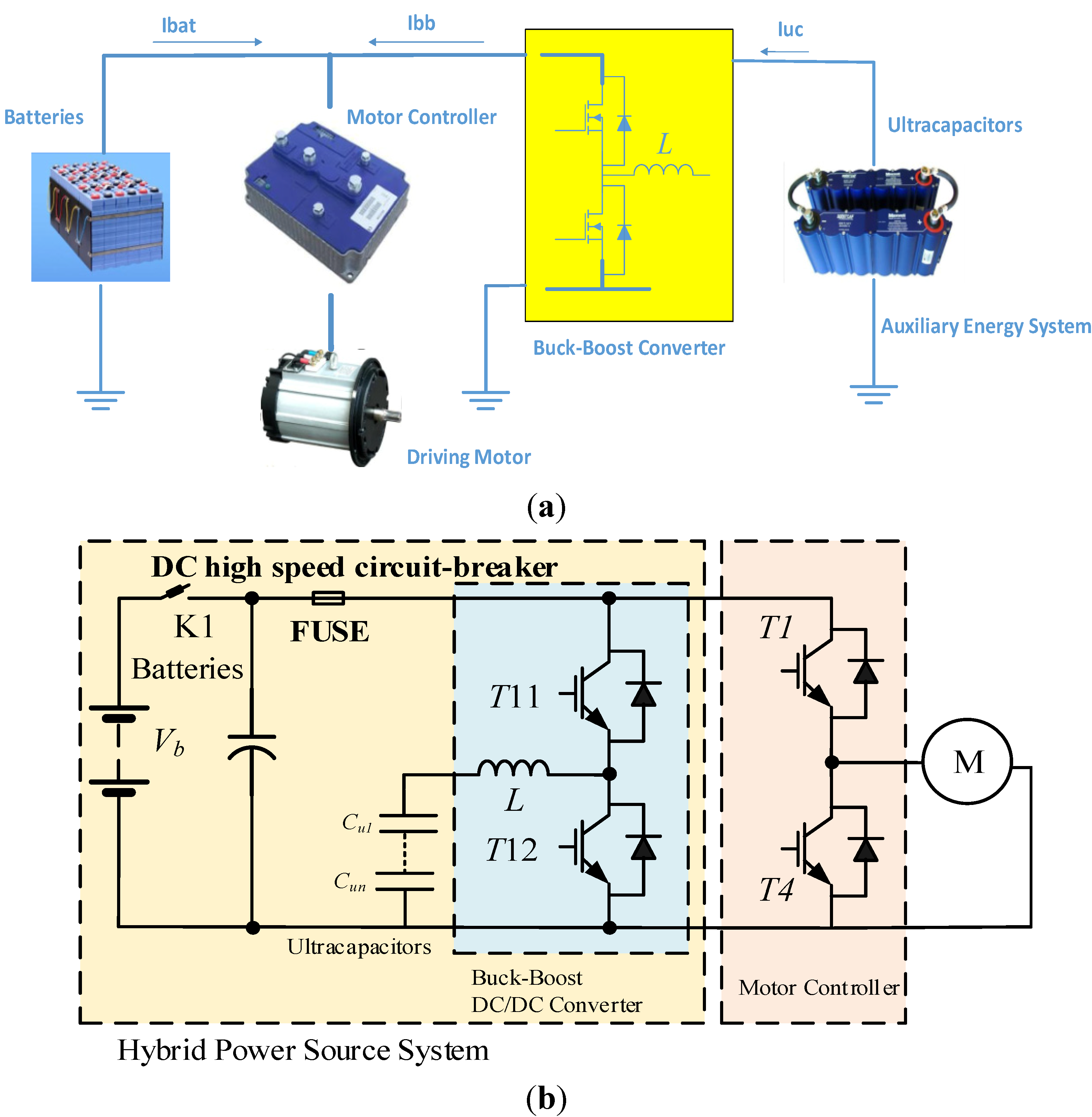
From the aforementioned description of the charging current direction in regenerative braking operation, we can know that the bidirectional DC-DC converter is assigned as an interface between the batteries and the ultracapacitors. The combination of batteries and ultracapacitors has the merits of high power density and specific energy. Hence, how to dynamically allocate the charging current between the batteries and the ultracapacitors is the key issue.
In [
17], Zhou
et al. established a speed control and current limitation control methodology for the energy management of an electric bus. This method can avoid the over-charging and discharging current of the batteries, yet, it reduced the dynamic performance of the PEV. In [
18], Schaltz
et al. put forward a power allocation scheme for the two power sources, which is realized by way of limiting the maximum power output of the batteries; this method has limitations on the improvement of the power-out efficiency, moreover, this control strategy has the drawbacks of complicated computation problems on the definition of average positive and negative power needs. Moreover, the influences of battery/ultra-capacitor energy-storage sizing on extending the battery lifetime are discussed.
From the above analysis, we can conclude that the best way for energy allocation of HPSS is to certify the needed power of EVs in use, which is decided according to the state of charge (SOC) of the batteries and ultra-capacitors, then, the energy allocation scheme can be realized by fuzzy control theory. Another solution is to put forward an objective optimization function which is composed of minimum battery energy consumption, the real maximum power output of EVs, the SOC of batteries and ultra-capacitors, the maximum output current of the batteries, and the variations of the acceleration pedal.
An optimal way to improve the energy recovery efficiency of HPSS is to detach the instantaneous charging current
Iac and the consistent charging current
Idc from the total braking power P
Brake, to realize this purpose, a current filter is needed.
Figure 3 shows the proposed scheme, where the instantaneous braking power can be decomposed into two components—high and low frequency current. Hence, the reference power for batteries can be derived by adding an additional low pass filter (LPF) to get the dc-current component, on the other hand, the high frequency current component
Ih can be derived by the difference between the total braking current
Ibrake and dc-current component
Idc. Since the ultra-capacitors are series together, state of charge (SOC) on ultra-capacitors should be considered, the current allocation for each UCs are different.
Figure 3.
Current allocation scheme for ultrapacitors and batteries in regenerative braking operation.
Figure 3.
Current allocation scheme for ultrapacitors and batteries in regenerative braking operation.
From
Figure 3, we may know that after being filtered by the LPF, the reference current for the UCs can be acquired by the difference of the DC-link current
idc and the DC-component of the DC-link current
ibat.
4. H∞ Design for HPSS
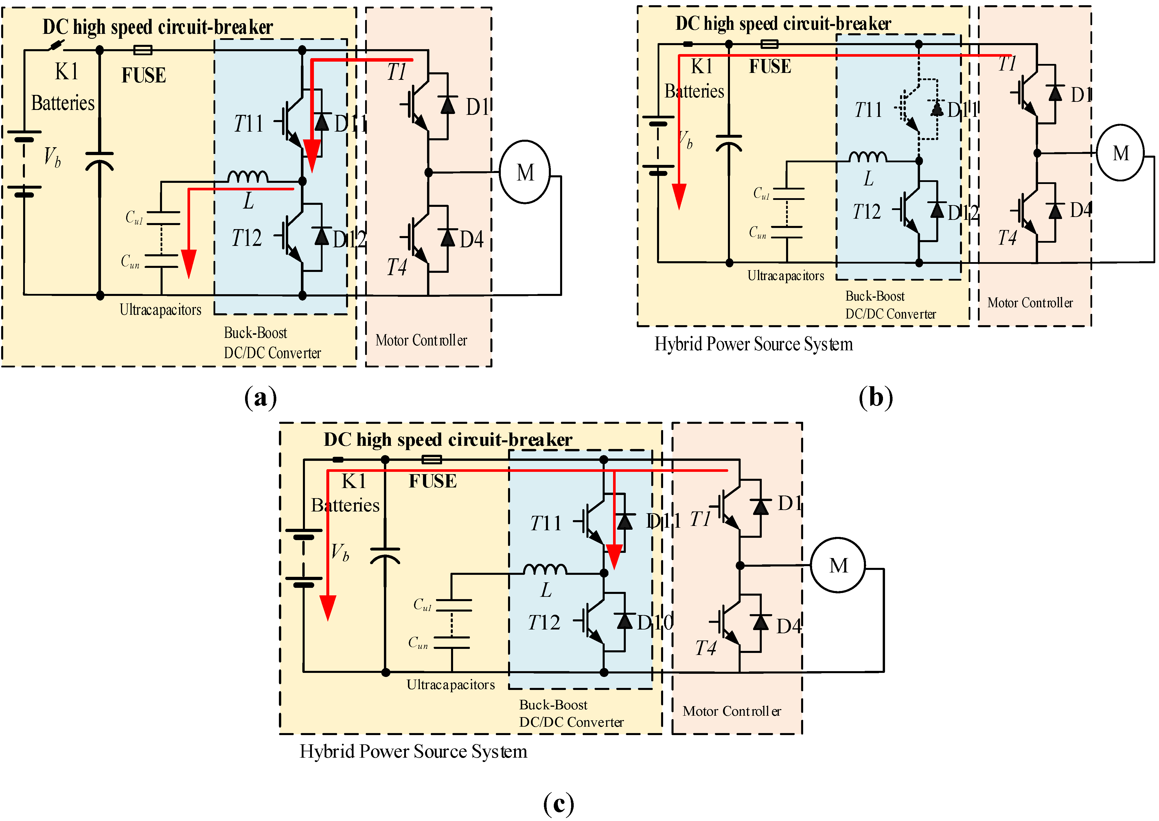
In the proposed scheme, either in driving or regenerative braking operation the bidirectional DC-DC converter is the key issue. The DC-DC converter contains power transistor T11 and T12, filter inductance L, equivalent resistance of the UCs, batteries rbat and the motor, and the driving motor. Since the structure of the two energy sources are similar, hence, the same equivalent circuit can be used for modeling, in the following parts, we will conclude the mathematical model of the hybrid power source system in regenerative braking operations.
4.1. Linear Small Signal Model in Regenerative Braking Operation
In regenerative braking operation, the back electromotive force (BEMF) of the motor, the DC-DC converter, the UCs and batteries form a closed circuit, The Kirchhoff’s Voltage Law (KVL) equation of the power circuit can be derived in continuous conduction mode (CCM):
In
Figure 1b, when T12 is
ON (0 ≤
t ≤
dTs),
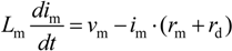
Ts is the modulation period of the power transistor. The regenerative braking energy is temporarily stored in the filter inductance. The voltage drop on the inductance would be:
In Equation (1), Lm is the filter inductance, vm denotes the BEMF of the motor, im is the motor current, rm and rd denote as the internal resistance of the motor and equivalent of the diode in on-state.
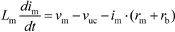
When T12 is
OFF (
dTs ≤
t ≤
Ts):
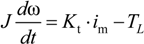
According to the electromagnetic torque equation:
Assuming that the state variable x = [im ω]T, output current is y = ib, back electromotive force (BEMF) expression of the driving motor is vm = Keω.
When T12 is
ON, the system matrix
A1, control matrix
B1 and output control matrix C
1 under regenerative braking can be derived as:
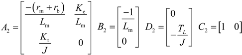
Similarly, When T12 is
OFF, the system matrix
A2, control matrix
B2 and output control matrix
C2 under regenerative braking operation can be derived as:
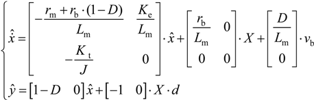
After being processed by perturbation, and steady state variable separation and instantaneous variable, the linear small signal model of the system can be written as:
4.2. H∞ Design for the Proposed Hybrid Power Source System
Nowadays, the H
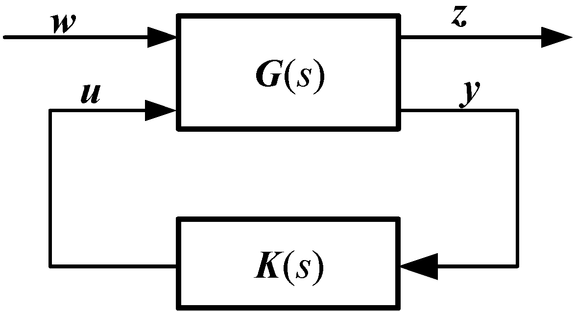
∞ control issues has been standardized, and block diagram of H
∞ design can be represented as shown in
Figure 4.
In
Figure 4,
u is the control input,
y is the measured output,
w denotes the perturbations, including disturbance, noise and reference input,
z symbols as the output control signal,
G(s) is augmented controlled object, including namely controlled device and weighing function designed for performance index, and
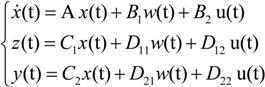
K(s) is the feedback controller needed to design. Assuming that the state-equation of the transfer function
G(s) can be written as:
In Equation (5),
x ∈ R is the state variable of the augmented controlled object;
B1,
D11,
D21 are the coefficient matrices for noise input signal
w; B
2, D
12 are the input control matrix;
C1 and
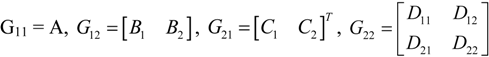
C2 are the state variable coefficient matrix, respectively. Equation (5) can also be written as the system matrix expressed as:
Then, the transfer-function of G(s) from noise signal input
w to output control signal z in
Figure 4 can be written as:
In Equation (7), LFT is the Linear Fraction Transformation function (LFT),
G11,
G12,
G21,
G22 in Equation (7) are defined as:
In the design procedure of a feedback control system, performance requirements of the closed-loop system include: robust stability, sensitivity to the disturbances, dynamic performance, and speed response error both in steady state and steady-state. Among them, robust stability and sensitivity to disturbance are especially important in a closed-loop system, and they are also the basic conditions for normal operation of a system. In order to reduce the sensitivity to perturbation and improve the robustness-stability of the system, special requirements are needed for the sensitivity-function in finite-frequency range. Compound sensitivity optimization has particular merits; by selecting a proper weighing function, it can force the system’s sensitivity function to be changeable within the expected rule, thus satisfying as a result, the requirements of the closed-loop system.
In this paper, based on the H
∞ compound sensitivity control theory, aiming at the HPSS system, a robust regenerative braking H
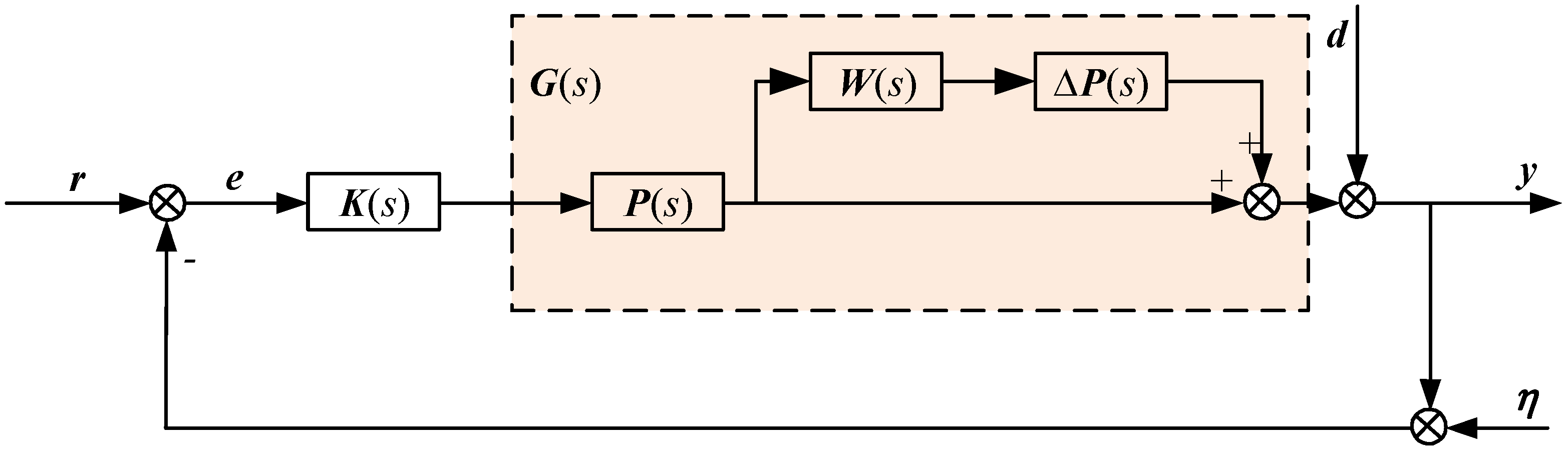
∞ is designed to guarantee the robust stability of the system under parameter variations and un-modelled component of the batteries and UCs, this method can minimize and disturbance caused by disturbances. The multiplicative uncertain feed-back control system is shown in
Figure 5.
Figure 5.
Multiplicative uncertain feed-back control system.
Figure 5.
Multiplicative uncertain feed-back control system.
In
Figure 5,
d is the outside perturbation signal, η is the measured noise of the system,
P(
s) is the nominal controlled device,
K(
s) is the needed controller,
W(
s) symbols as the multiplicative model uncertain function. As is shown in
Figure 5, the necessary and sufficient conditions of closed-loop control system to ensure the robustness of the system is:
where
T =
PK(
I +
PK)
-1 is defined as the complementary sensitivity function. If the variations of the system △
P(
s) = 0, the system’s output can be deduced as:
Hence, the tracking error of the system for the reference
r would be:
4.3. Weighing-Function Selection
Since the H
∞ design problem can be realized by solving two Riccati equations [
13,
14,
15,
16,
17,
18], the mixed-sensitivity design can be changed to a standard H
∞ control problem,
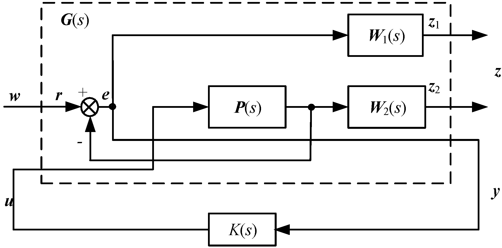
Figure 6 gives the transformed H
∞ control of a mixed-sensitivity design problems.
Figure 6.
The mixed-sensitivity design methodology diagram being transformed to a H∞ standard controller.
Figure 6.
The mixed-sensitivity design methodology diagram being transformed to a H∞ standard controller.
In
Figure 6, the augmentation controlled system G (s) is:
The closed-loop transfer-function
Tzw(s) of the system from
w to
z in
Figure 6 would be:
in which,
Fl(
G(
s)),
K(
s)) is the linear fractional transformation, thus, we need to design a feedback controller
K (
s) which can ensure the stability of the closed-loop system and satisfy the inequality:
In
Figure 6,
W1(
s) is the weighing function for sensitivity function
S—it reveals the ability to resist perturbation and tracking performance. Normally, the smaller value the singular value of the sensitivity function is, the better performance it has to resist perturbation and tracking ability.
W2(
s) is the weighing function for the complement sensitivity function
T, It can be selected according to the system’s high frequency un-modeled part. Therefore, the dynamic performance of
W2(
s) is mainly decided by the uncertain part at its high frequency part, in addition, in order to realize noise suppression, it is required that the sensitivity function
T should be small at the high frequency band, the norm function of
W2(s) should be large enough at high-frequency section, in addition, frequency of
W1(
s) and
W2(
s) should not be overlapped, and the exponent of
W2(
s) need not be too large. Weighing function
W3(
s) is used to restrain the value of control signal, it also affects the system’s bandwidth as well, in order to keep the system’s exponent invariable, normally,
W3(
s) is chosen as a constant. As the exponent of H
∞ is equal to the sum of the controlled object and weighing function, in order to get a low exponent H
∞, it is better to choose a low exponent weighing function under the guarantee of the system’s design requirements.
After being regulated many times using Matlab/robust toolbox, the frequency weighing function of the H
∞ of the EVs in regenerative braking operation can be written as:
According to the mathematical model described in Equation (4), and the suggested weighing function in Equations (14)–(16), The frequency weighing composite sensitivity H
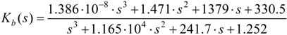
∞ can be derived as:
Assuming that the sampling time
T = 0.002 s, after being processed by bilinear transformation, the discrete controller in regenerative braking mode would be derived from Equation (17) as:
5. Experimental Results
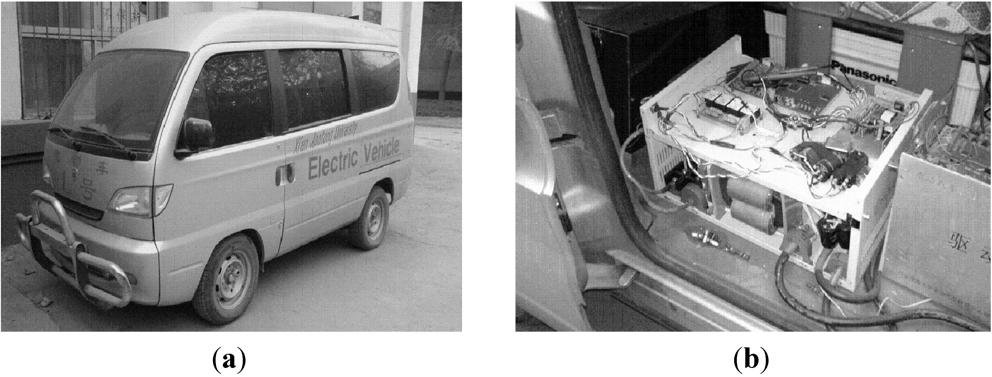
In order to validate the proposed scheme, an HPSS system hardware platform using a digital signal processor (DSP)-TMS320F28335 (Texas Instruments, Dallas, TX, USA) has been set up in the laboratory (see
Figure 7). The PID controller parameters (actually, a PI controller instead of a PID controller is utilized when in use in case of system oscillation which may be caused by an improper choice of the
kd coefficient) in experiments are chosen by simulation verifications using Matlab/SimPowersystem. Specifications of the HPSS used in the hardware platform are listed in
Table A1 in the Appendix. The parameters of PID controller are
kp = 1.5,
ki = 0.002,
kd = 0, sample time
Ts= 4 μs, respectively. The experiment is performed with two main objectives:
- (a)
In motoring operation, when the PEV needs an instantaneous and peak power output, and meanwhile, the ultra-capacitors are fully charged and have stored enough energy, the HPSS is controlled as a boost DC-DC converter which works in parallel driving mode. The additional energy is provided by the ultra-capacitors and batteries.
- (b)
Since the ultra-capacitor has the merits of high energy and power density, and high efficiency of charging and discharging current. In deceleration or braking operation, the ultra-capacitors have priority to be charged. A constant power charging control strategy is implemented in this paper, which means position of the pedal determines the braking power command. The maximum braking power reference is limited to 10 kW.
Figure 7.
Hardware setup for experiments. (a) Electric vehicle; (b) controller for HPSS using DSP.
Figure 7.
Hardware setup for experiments. (a) Electric vehicle; (b) controller for HPSS using DSP.
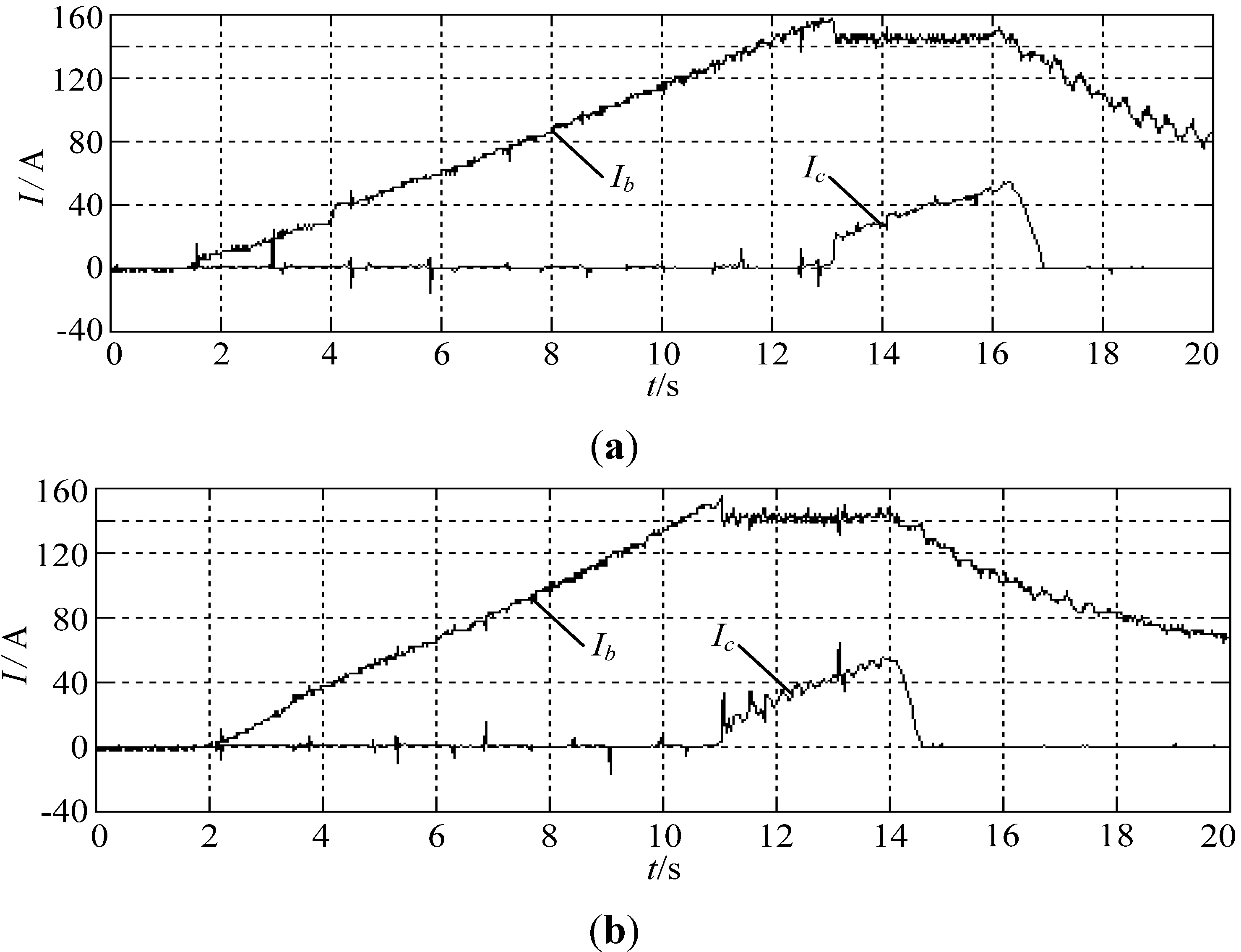
Figure 8 illustrates the experimental results of HPSS under motoring operation, in which,
Ib stands for the batteries’ discharging current,
Ic stands for discharging current of the ultra-capacitors. In motoring operation, the DC-DC converter acts when the discharging current of the batteries
Ib is greater than 140 A; the additional current needs are supplied by the ultra-capacitors, in this way, the batteries can be protected from over-discharging.
Figure 8.
Discharging current of the batteries and ultra-capacitors under motoring operation. (a) PID controller; (b) H∞.
Figure 8.
Discharging current of the batteries and ultra-capacitors under motoring operation. (a) PID controller; (b) H∞.
Also seen from
Figure 8, we may realize that both PID and H
∞ can perform very well, the total discharging current
Idc is well constrained to 140 A, yet, the performance indicates that the steady state error and time response of H
∞ are superior than that of conventional PID controller. The steady state error
ess and time response of PID controller are:
ess_pid ≈ 5 A,
tpid = 13 s, respectively, for H
∞, they are:
ess_H∞ ≈ 2 A,
tH
∞ = 11 s. Hence, the H
∞ has much faster time response (2 s) than the PID controller, which is caused by a large integral variable existing in the PID controller. The larger the integral coefficient is, the slower the time response would be. On the contrary, Equation (18) is discrete, which does not have any integral component, so it is easier for fast implementation. It should also be noted that the smaller the upper limit of batteries’ discharging current is, the larger its available capacitance would be, but this upper limit is constrained by the maximum energy stored in the ultra-capacitors. If the energy stored in the ultra-capacitor is large enough, it would be better if the batteries’ reference discharging current is restrained to be a relatively smaller value. This would be beneficial for improving the available capacitance of the batteries. In our experiment, the energy stored in the ultra-capacitors is relatively smaller, that is why the batteries’ discharging current is set to 140 A.
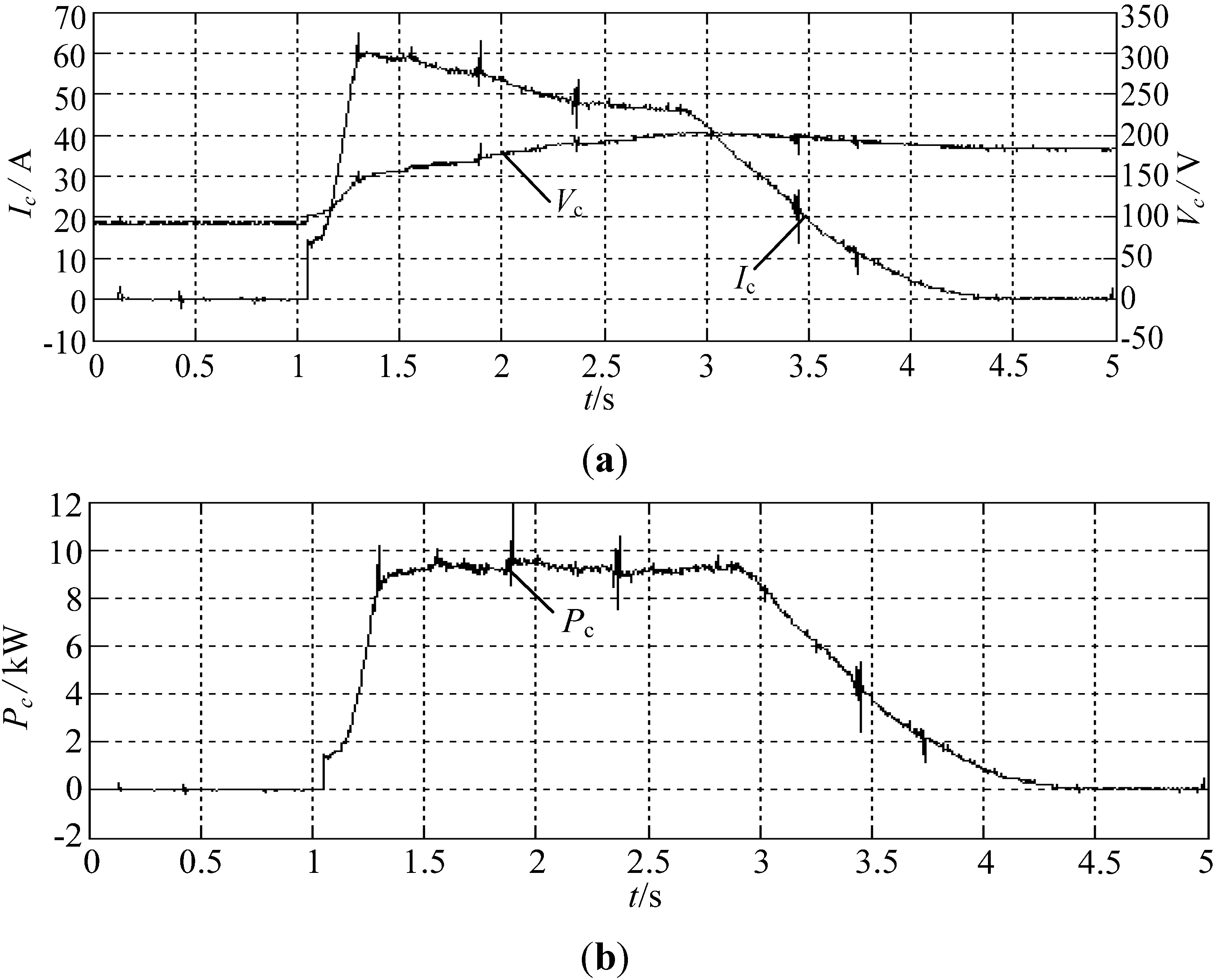
Figure 9a illustrates the charging current of the ultra-capacitors using PID controller and H
∞, respectively, under regenerative braking. The terminal voltage of the ultra-capacitors V
C and their charging current
Ic are also provided. It can be clearly seen that the regenerative braking operation starts at 1 s, the charging current of the ultra-capacitors increases from 0 to 60 A (peak value). This procedure lasts about 0.25 s. After that, the EVs slow down, and the charging current starts to decrease, at 4.5 s, the charging current, again, is reduced to 0 A. The ultra-capacitors’ terminal voltage increases from 100 to 200 V during the braking procedure.
Figure 9b shows the charging power of the ultra-capacitors P
c, since the reference charging power of the ultra-capacitors is constrained to 10 kW, the experimental shows that the charging power is well controlled to the reference value, and this procedure lasts about 3.5 s.
Figure 9.
Charging current of the ultra-capacitors using PID controller in regenerative braking operation. (a) Terminal voltage of the ultra-capacitors Vc and charging current Ic; (b) charging power of the ultra-capacitors (Pc).
Figure 9.
Charging current of the ultra-capacitors using PID controller in regenerative braking operation. (a) Terminal voltage of the ultra-capacitors Vc and charging current Ic; (b) charging power of the ultra-capacitors (Pc).
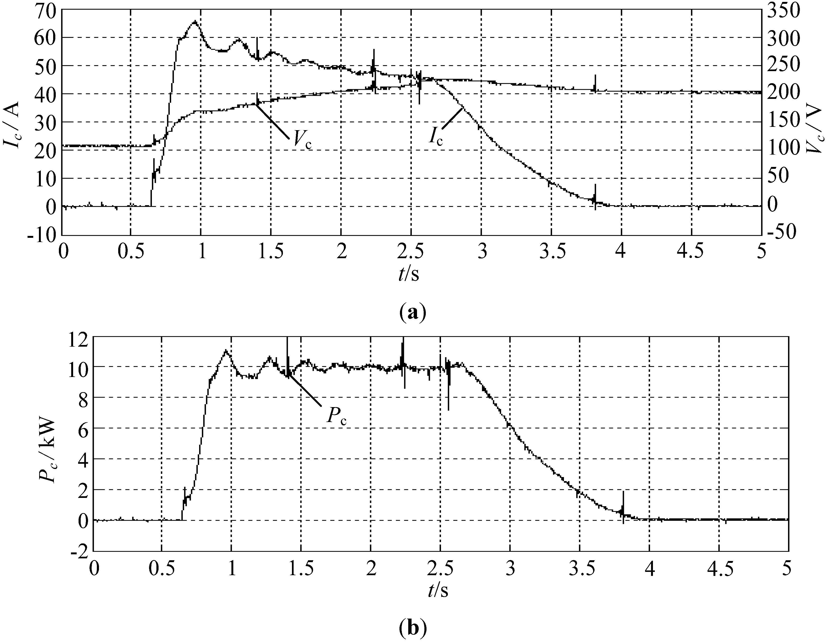
Compared to a conventional PID controller, H
∞ is also adopted in our implementation.
Figure 10 shows the charging current of the ultra-capacitor pack using H
∞ under regenerative braking. As compared to
Figure 9, we can conclude that sliding mode controller is superior to the PID controller in steady state error and time response. From
Figure 9b, we can conclude that the average charging power is about 10 kW for H
∞ and 9.5 kW for PID controller, which means that the H
∞ could acquire more energy (about 5.3%) than the PID controller under the same conditions.
Figure 10.
Charging current of the ultra-capacitor pack using H∞ under regenerative braking. (a) Terminal voltage of the ultra-capacitors (Vc) and charging current Ic; (b) charging power of the ultra-capacitors (Pc).
Figure 10.
Charging current of the ultra-capacitor pack using H∞ under regenerative braking. (a) Terminal voltage of the ultra-capacitors (Vc) and charging current Ic; (b) charging power of the ultra-capacitors (Pc).


