1. Introduction
Belt conveyor systems are used to transport raw materials inside mines over long distances (up to several dozens of km) [
1,
2]. They usually are in operation nearly 24 h/day, often in harsh environmental conditions, especially in underground mines. It is obvious that they are subjected to faster degradation processes. According to mining law as well as internal regulations in enterprises, they should be inspected on a regular basis.
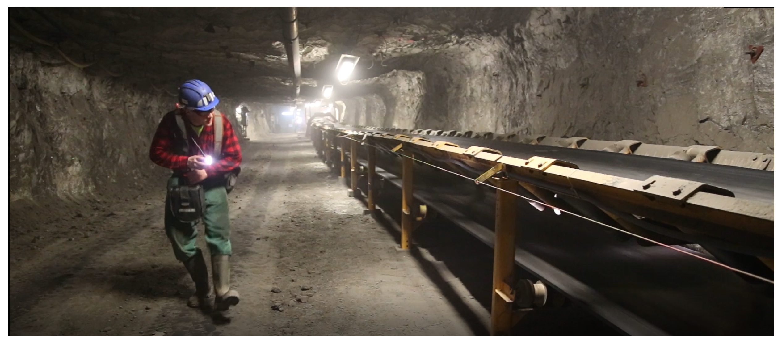
Normally, some elements of the conveyor (drive units) are monitored 24 h/day using SCADA systems. The rest of the conveyor is inspected by maintenance staff. This requires visual checking of all elements along the conveyor in order to search for anomalies; see
Figure 1.
Unfortunately, conveyors require high power and are spatially distributed over a large area. In practice, this means inspectors must walk many kilometers in very difficult environmental conditions (humidity, temperature, mud on the surface, noise, dust, potential gas hazard [
3,
4]). Rotating elements and moving belts are examples of elements with potential sources of accidents. According to state mining authorities one of the most frequent reason of accidents is related to human–machines interactions [
5].
Thus, mining companies are looking for alternative approaches to maintain conveyors. As mentioned, there are two types of problems: the first one is related to key parts of conveyors, such as drive units and return pulleys, that can be monitored by installed sensors and data acquisition systems [
6]. There are many solutions for such machine monitoring, including drive units [
7], transfer points [
8], belts [
9,
10], and belt splices [
11]. These elements are stationary (electric motor, gearbox, pulley, transfer points) and can be monitored by stationary sensors. Even if the element is moving, such as a belt, one can use stationary sensors to investigate the conditions of the belt.
The most critical are the remaining components of the conveyor, with hundreds of rollers installed along the conveyor route and belts moving on these rollers. The direct method to replace human-based inspection is by introducing mobile robotic platforms with appropriate sensors and data acquisition/transmission systems. Inspection robots for mining applications have already been developed by several research teams [
12,
13,
14,
15,
16,
17,
18,
19,
20]. A specific case is related to conveyor belt inspection [
15,
21,
22,
23,
24,
25,
26,
27].
However, using inspection robots in the mine is challenging due to several issues. In an underground mine, one of the biggest challenge is localization and navigation [
28,
29,
30,
31,
32,
33]. In [
34], the problem of positioning the robot is discussed in indoor conditions, where GPS signals might by not be available. This is also the case for underground mines, and this is the ultimate goal for our work. In [
34], the authors proposed a combination of IMU-based odometry and a vision system. Szrek et al. [
35] analyzed various localization techniques in the context of their applications in underground mines.
Another important issue is the harsh environment [
36] and the geometry of the supervised infrastructure. It can be assumed that average length of the conveyor is 1 km. Maneuvering in mining conditions over such distances is also a challenge. Unmanned Aerial Vehicles (UAVs), Unmanned Ground Vehicles (UGVs) and walking robots have been tested for this purpose according to the literature [
15,
23,
24,
25,
37,
38,
39,
40,
41].
Due to powder/dust conditions, UAVs are hardly acceptable in underground mines. Additionally, in comparison to UGVs, legged robots are much more complicated. Therefore, for our application, a UGV seems to be optimal due to speed, payload, stability and battery usage.
To minimize the presence of humans in the harsh environment, we propose a mobile inspection platform based on autonomous UGV. It is equipped with various sensors (RGB image, sound, gas sensor, etc.), and thus is able to collect almost the same information as a maintenance inspector. Till now such experiments have been performed in labs as well as in mines [
12,
15], but the robot was remotely controlled by an operator.
In this paper we introduce the general concept of an autonomous robot-based automatic inspection. A framework of how to deploy the inspection robot for automatic inspection (3D scanning of the tunnel, 3D model, path planing, etc.) is defined and some first results from automatic inspection tested in lab conditions are presented. Differences between the planned and actual path are evaluated. We also point out some challenges for further research, especially for planned validation in underground mines.
2. Problem Formulation
The purpose of this work is to perform automatic inspection missions to support the daily maintenance of belt conveyors in mines. An autonomous drive in the mining tunnel with mining infrastructure is challenging. First of all, one needs a detailed map of the tunnel (which needs to be prepared during the so-called “training”). Then, some key points (start/stop of the mission, start/stop of data recording, specific and characteristic points on the path where the robot should slow down, take special care, turn, etc.) should be addressed on the map to create a desired path. Finally, during execution, one could expect to measure how precise the robot is (i.e., if its location matches the planned route). Thus, the problem addressed in this paper is to develop a general framework describing what steps should be taken to achieve the goal, i.e., automatic inspection of infrastructure.
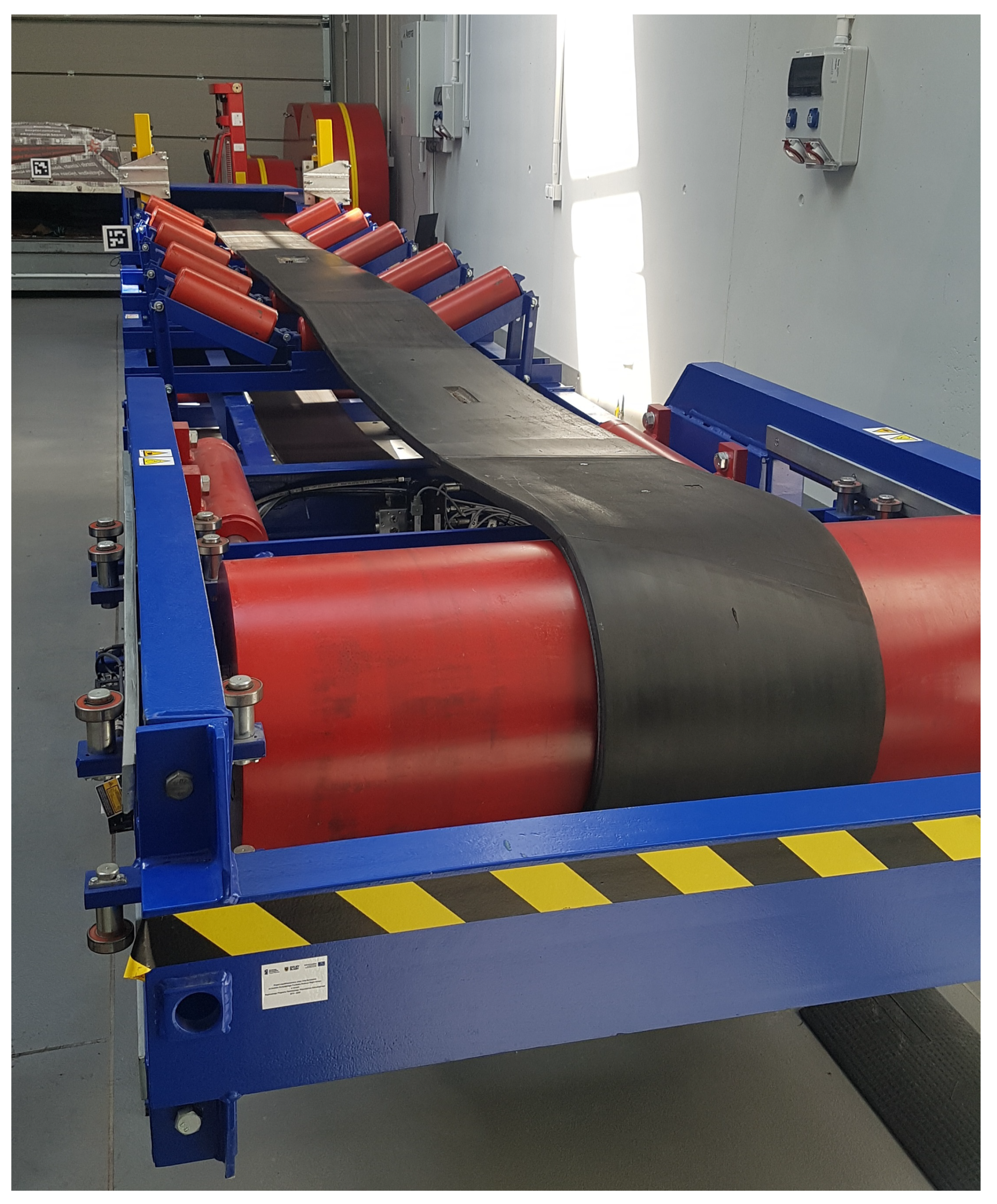
As field experiments in deep mines are difficult to organize and costly, and there is very limited time to test/validate the system, it was decided to spend as much time as possible in laboratory conditions with a belt conveyor test rig designed for research purposes (see
Figure 2).
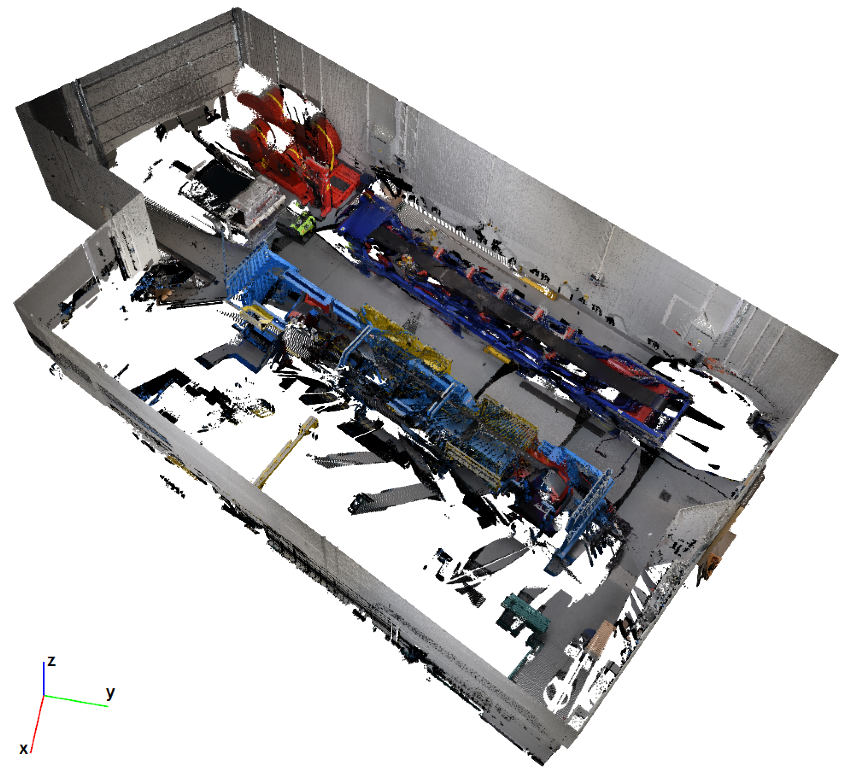
A point cloud map of the laboratory that was collected using a high resolution stationary geodesic LIDAR (see
Figure 3) is available as a reference for experiments.
An analysis of the requirements of the automatic inspection process has led us to divide the process into two separate parts: inspection planning and execution.
In the first part, the procedure of the inspection is transformed into elementary tasks for the robot. It includes defining paths to be followed and measurements to be taken associated with certain locations. As the planning is expected to be performed once for a given conveyor setup, it is less time-restricted, and a part of it, which requires additional computations, can also be performed off-line.
The inspection execution is meant to follow the plan defined in the first part, providing a report with a current state of the conveyor. As this part is periodically repeated, it should follow two principles: minimize deviation from the plan and the time needed to complete it.
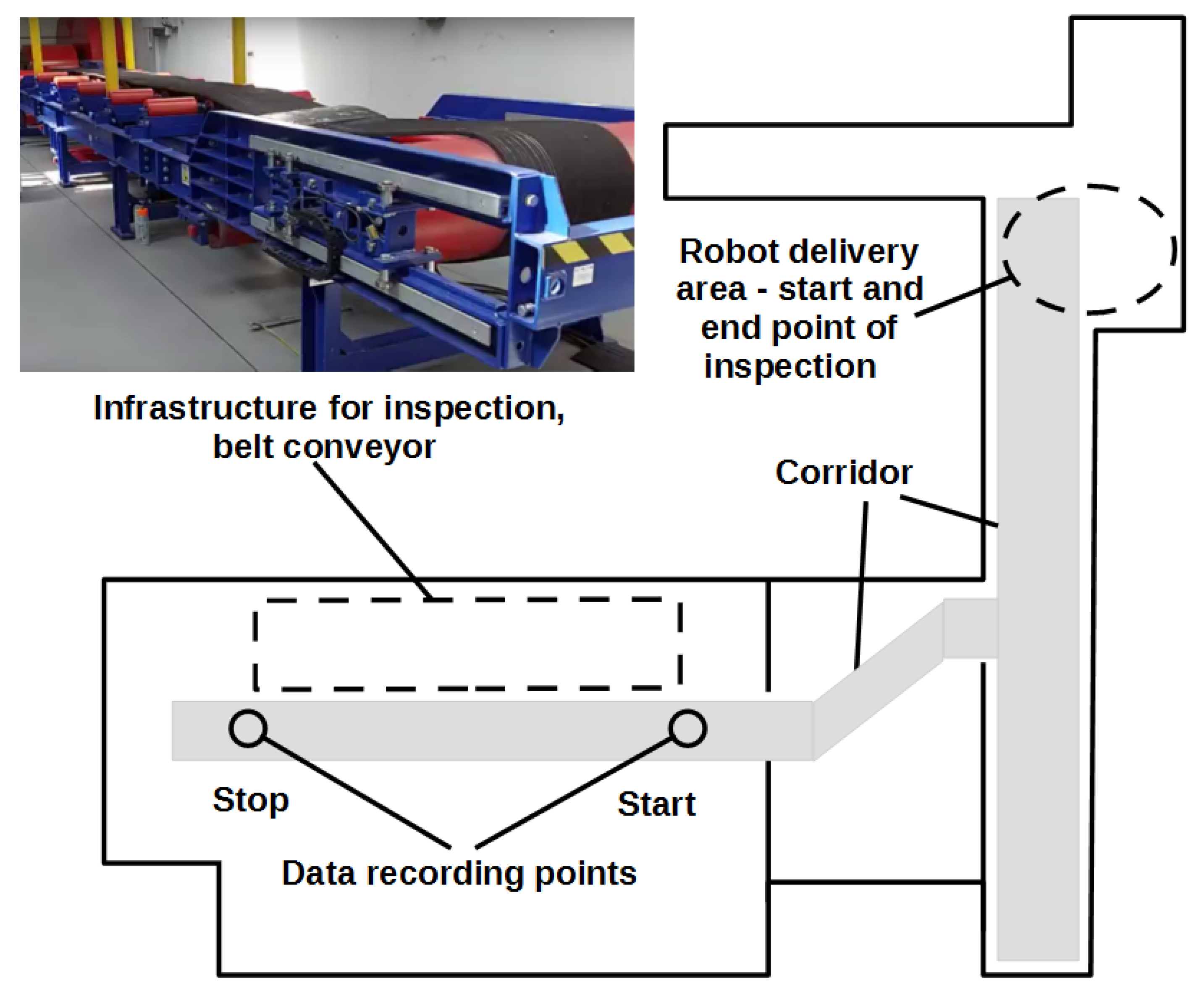
In this paper we propose a procedure for the automatic inspection. Furthermore, we present a system, including its components and their functions, that was developed to validate the procedure in laboratory conditions. To summarize the whole mission route, the robot should go from a starting point in the corridor, pass several turns, start the measurement process at the beginning of the conveyor, travel to the end of the conveyor and back while taking the measurements, arrive at the beginning of the conveyor, stop data acquisition and return to the starting point in the corridor.
Figure 4 shows the general plan of the facility with the relevant areas marked for the planning of the inspection mission.
It is assumed that the the robot will be delivered by a special car that is used for transport of materials close to the corridor with the belt conveyor (note the large distances in the mine). The second area is the corridor where only the robot can move. The last area is the area to be inspected, with the starting and ending points of data recording.
It is obvious that we should provide the map and characteristic points to the robot, so first a “training mission” for 3D scanning of the surroundings should be carried out. Next, we indicate key points of the mission on the obtained map and the robot is ready to go.
3. UGV Platform Description
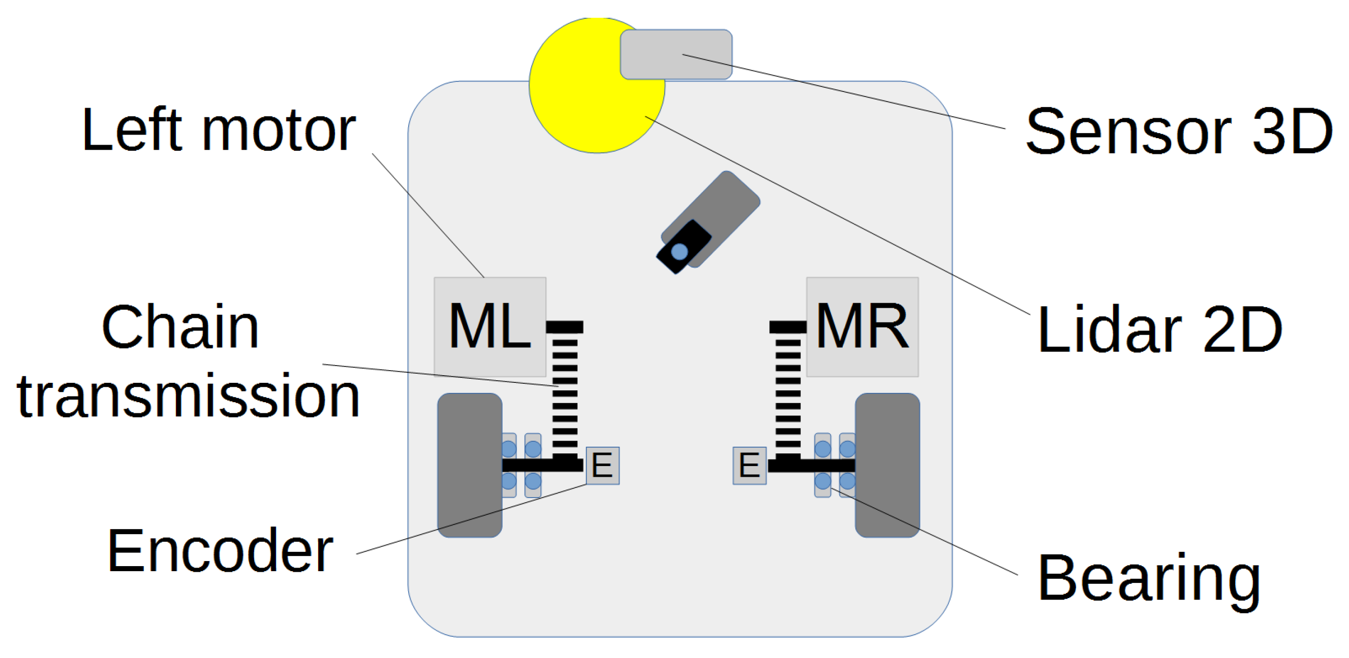
The UGV platform has two driving wheels attached to the platform in a classic 2.0 class system. The third, self-aligning wheel is a support element that allows to maintain the stability of the platform and will not be taken into account in further considerations. Maneuvering is done by changing the speed of each wheel (see
Figure 5). Lidar 2D, used for mapping, is shifted relative to the center of the robot, to avoid collision with the front wheel, and the 3D sensor has been placed centrally.
The robot’s wheels are driven by 250 W, 24 V DC motors integrated with the gearbox. Additional gear ratio and displacement of the drive motor axis in relation to the wheel axis was achieved thanks to the use of a chain transmission. The power supply of the robot is 24 V and it is supplied with a Li-Ion battery with a capacity of 20 Ah.
3.1. Kinematic Model
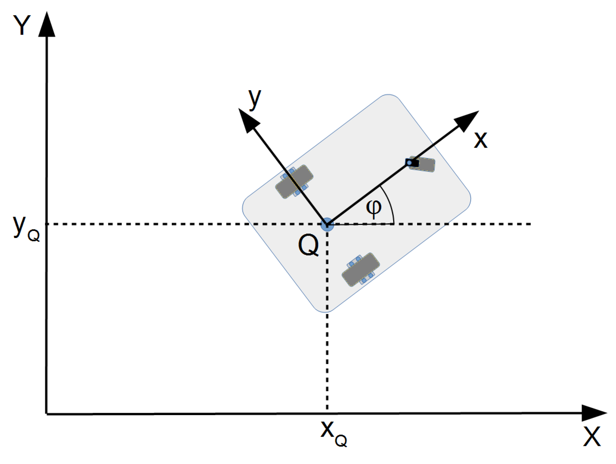
The mobile platform consists of a rigid body to which wheels are attached. The space in which the robot will be described is shown in
Figure 6.
Assuming that the robot moves on a plane surface, three parameters are sufficient to describe its position in space. Two of the parameters define the position of the robot on the
plane, and the third one is used to describe its
orientation, which can be represented by the parameter vector (
1) considered in the global coordinate system
.
For a detailed description of the platform movement, geometric parameters are required, as shown in
Figure 7. These are the radius of the wheel and the track width. Given the expected speed of the robot’s
V and the angular velocity
, the speeds of the left (
) and the right wheel (
) are then calculated.
Figure 7 shows the instant center of rotation, around which the rotation of the platform takes place.
In order to describe the robot’s motion in space, let us associate the local coordinate system
with it and assume that there is no lateral skid of the robot’s wheels, which is the same as ensuring zero velocity along the
y-axis [
42,
43].
The linear velocity
v is one of the input parameters (See
Figure 7) together with the angular velocity
, as described in (
2). Bearing in mind the geometrical parameters of the platform, in particular
R—wheel radius,
L—wheel track, and
—linear velocities of the left and right wheels, respectively, the dependencies (
3) can be written.
The platform has two independently driven wheels, so due to the hardware structure of the control system, dependencies describing the relation of the speed of particular robot wheels to the input parameters should be written as well, in the following form: (
4).
The kinematic model of the mobile platform in the form of (
2) has natural input parameters, such as linear velocity and angular velocity, and is, e.g., used in trajectory planning algorithms. From the point of view of the low-level control system in which the process of setting control parameters to individual platform drives is carried out, the (
4) dependencies apply, which link the speeds of individual wheels with the speeds (
v,
). The block diagram of the platform control system is shown in
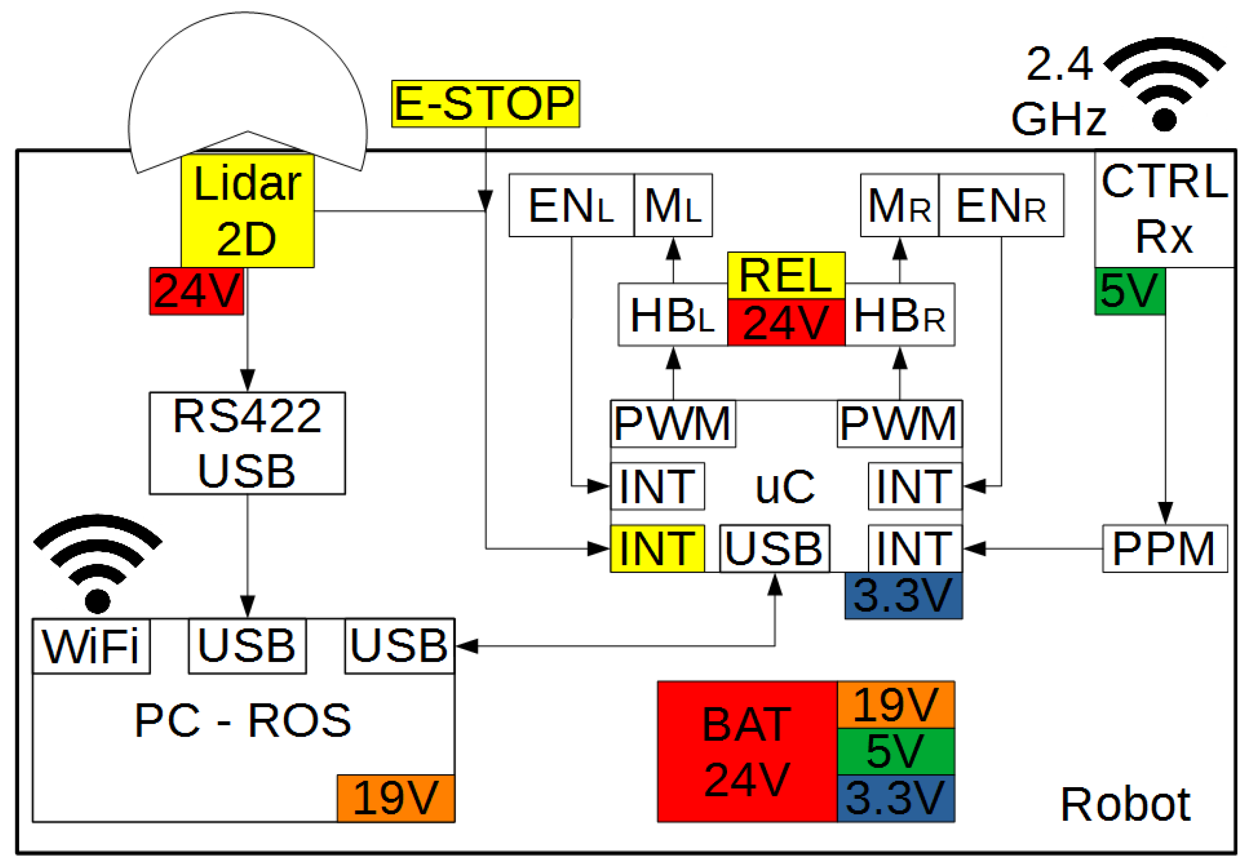
Figure 8.
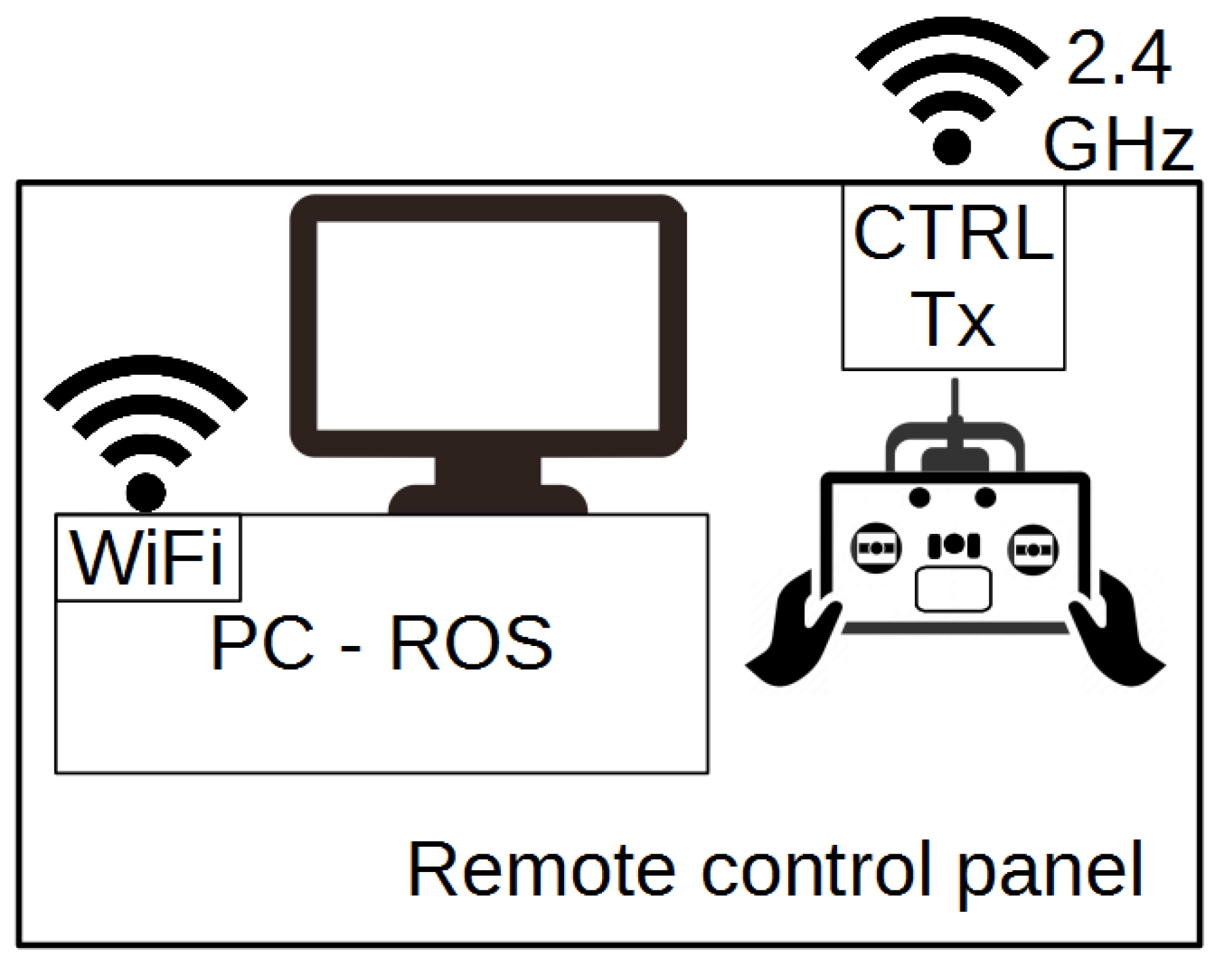
The drives are controlled by a module based on an STM32 microcontroller with an ARM Cortex M3 (uC) core. PWM signals are generated in the timer block, which sets the speed of the robot’s drives via H-bridges (HB). The feedback loop consists of AS4050 (EN) incremental magnetic encoders mounted on the wheel axis. The signal from the encoders is read with the use of external interruptions of the microcontroller. The speed of the robot’s drives is regulated with the use of a PI controller. The value of the expected speed is read via the USB port from the host computer-level (PC-ROS) based on the Intel NUC single-board unit. The master computer also receives the current speed value and signals read from the receiver of the remote control panel, thanks to which the robot can be controlled manually or switched to an autonomous mode. In the master computer, the robot localization and navigation algorithm are implemented. Spatial information is provided from the SICK S300 2D scanner, via the USB port using the RS422/USB converter.
Control of the robot is possible in either manual or autonomous mode. Switching between the modes is done remotely from the RC transmitter. One can also remotely view the current state of the robot using the WiFi network generated by the robot’s computer (
Figure 9).
3.2. Platform Navigation
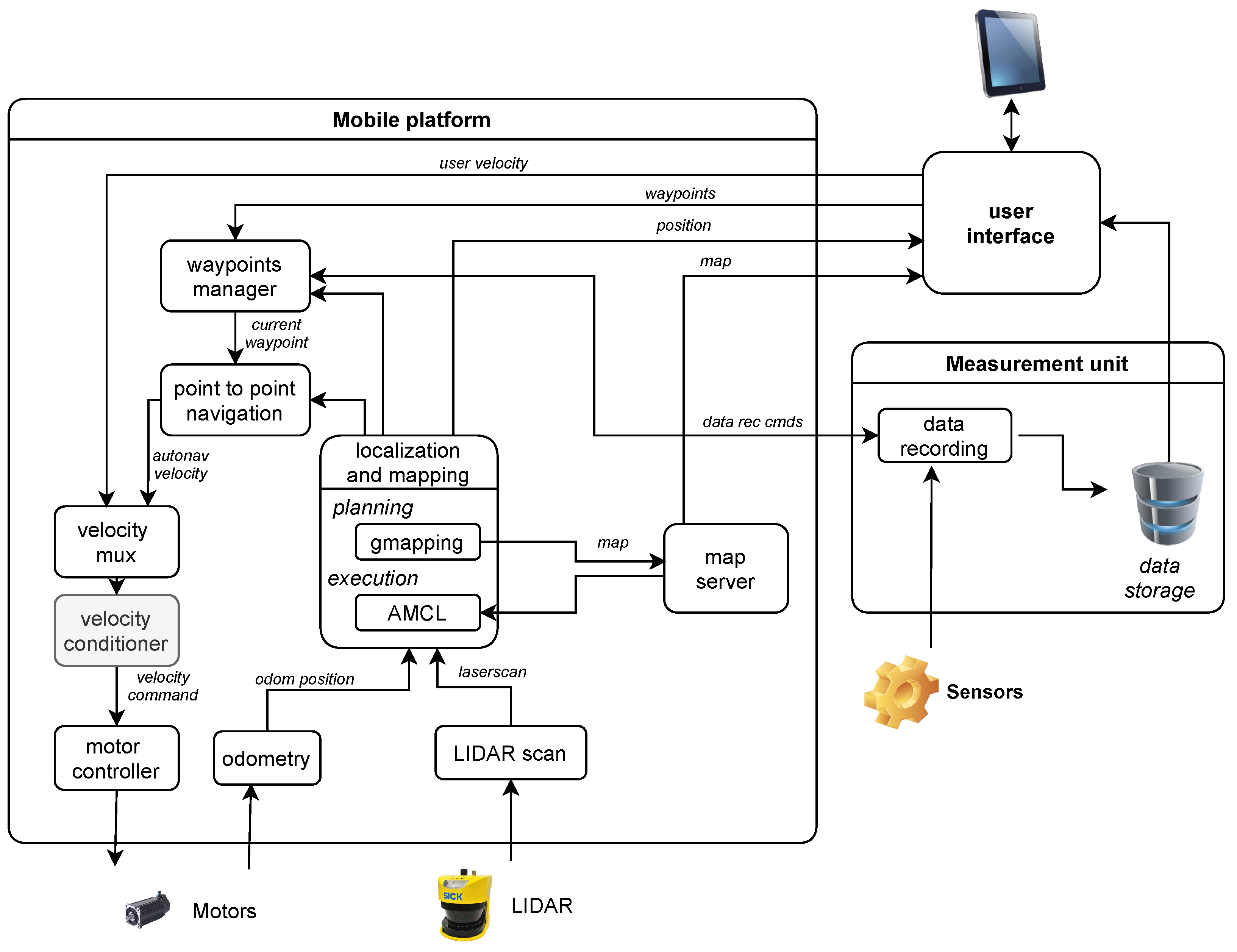
The navigation of the platform is implemented within the Robot Operating System (ROS) framework. The architecture of the system is presented in
Figure 10.
The architecture contains three main logical subsystem: mapping and localization, autonomous navigation and motion execution.
3.2.1. Mapping and Localization
The robotic platform in the experiment setup is assumed to move on a flat, planar surface. Additionally, the main mapping and localization sensor, SICK LIDAR, scans the environment in a single plane. Therefore the map is limited to a 2D map and the pose vector is limited to three coordinates.
The tasks of localization and mapping may be solved at the same time, as a Simultaneous Localization And Mapping (SLAM) problem, or separately. The latter approach separates mapping, when a map is built using the sensor data and high precision robot pose, and localization, when a fixed, previously built map is used to determine the current robot position with respect to this map. Solving the tasks separately is much less complex and requires lower computation power, but is less robust and imposes additional constraints on the system.
In our system we have decided to use a mixed approach. In the planning part we use full SLAM. As we assume that no precise robot pose is provided by any sensor, the additional estimation of robot pose from SLAM is necessary. That approach may require slower movement of the platform during map building, even with temporary stops to process data. However, during the inspection part we assume that the environment is not subject to major changes and therefore we can use the fixed map and solve only map-based localization problems. Additionally, the localization task alone is expected to be computed online even when the robot moves at a full speed.
That difference in behavior is illustrated in the “mapping and localization” block in
Figure 10. The actual composition of this block depends on the stage of operation in which the platform is. In the preparation area mapping stage, it performs a map building process based on the robot position from the odometry and detected fixed objects from the robot environment. It uses a Rao–Blackwellized particle filter SLAM approach [
44] from the
slam_gmapping package. The map building process provides a 2D occupancy grid map with cells indicating free, occupied and unknown areas. In the inspection stage, the map built and recorded in the mapping stage is used as a fixed reference for platform localization. In this stage, an implementation of the Adaptive Monte Carlo Localization (AMCL) algorithm [
45] from the
amcl ROS package is used.
3.2.2. Autonomous Navigation
The path to be followed during the inspection stage is represented as a list of waypoints to be passed with an additional tasks for a data recording system planned in key waypoints.
It is governed by a waypoint-following component based on a finite state machine. The component tracks the distance to the current goal point. When the point is reached, a communication with the data recording system scheduled for that point is executed. Then, the next point from the path is sent to the motion control component. The steps are repeated until the last point of the planned path is reached. The motion control component is compatible with the ROS navigation stack; however it does not use the standard ROS planners. Instead, a dedicated component is implemented. This was motivated by the requirement of repeating the same path in each inspection pass so that the measurements are recorded from the same locations. It is assumed that the robot follows a line segment between the previous and the next waypoint with a given maximum allowed deviation from the line. As long as the robot remains within these boundaries, it moves with the maximum allowed velocity, correcting the motion on the fly. When the deviation exceeds the given limits, the robot’s forward movement is stopped and its heading is corrected with in-place rotation.
3.2.3. Motion Execution
The task of the motion execution component is to receive control commands from the autonomous navigation and the operator panel, select the command to be executed and communicate with the motor controllers. It also provides the odometric localization calculated from encoder inputs for mapping and localization components. The components uses internally forward and backward kinematics of the differential drive model to translate velocities from the external world coordinates to wheel angular velocity and encoder signals to robot position and orientation. The selection of the actual control uses prioritized multiplexing, where the remote control by the user overwrites the output of the autonomous system to ensure safety in emergency situations.
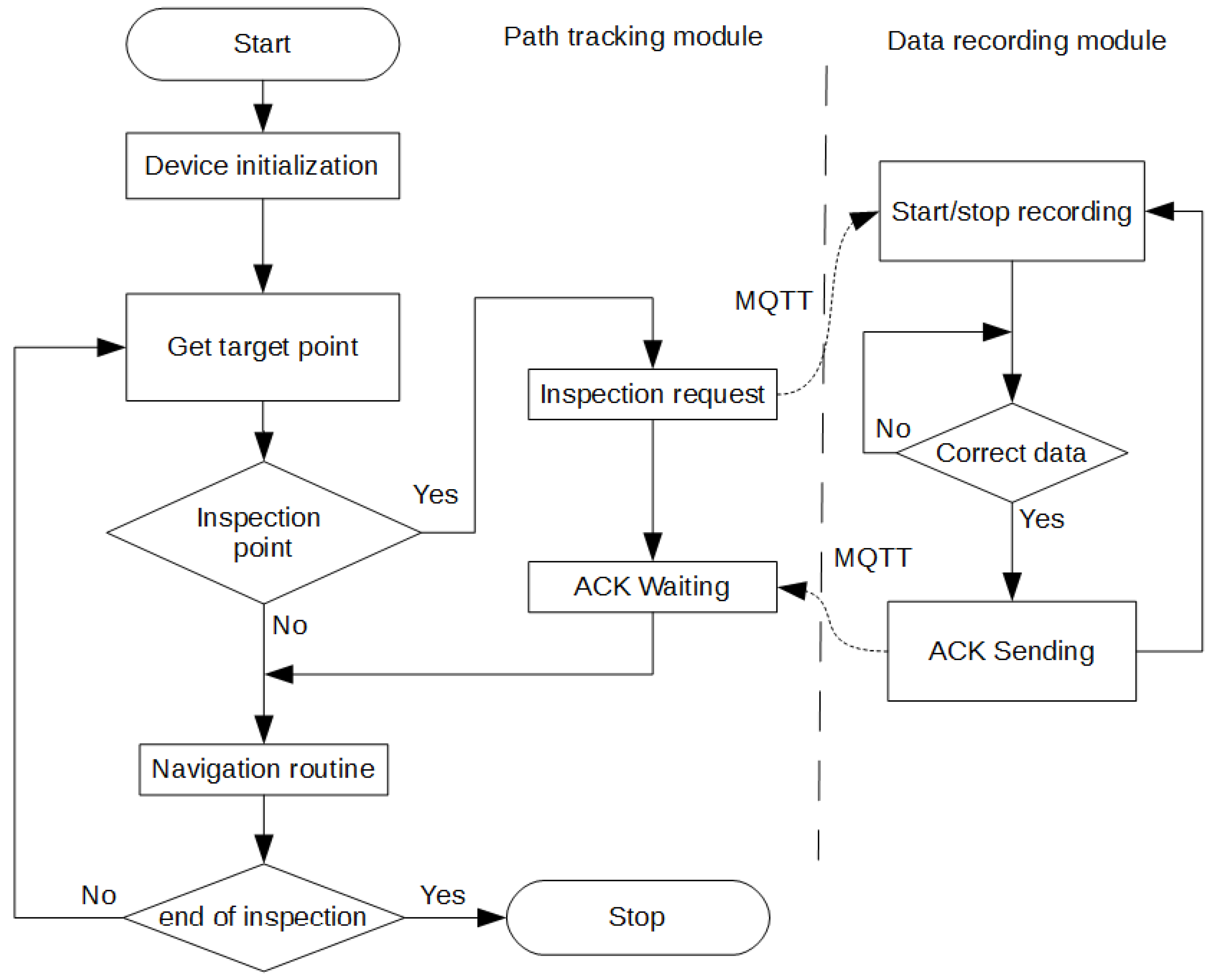
3.2.4. Inspection Algorithm
The MQTT protocol governs the communication between functional program modules. It gives great flexibility in data transfer between different operating systems and programming languages. When the inspection start point is reached, a request is made to start data logging (see
Figure 11). After initializing the measurement systems operation and saving the data, the module responsible for registration sends a confirmation message. After receiving the confirmation, the robot downloads the next path points until obtaining the information that the point at which the measurements are to be stopped has been registered. After stopping data recording, the robot loads further path points, which lead to the location where the mission ends. In order to secure the measurement system, the maximum waiting time for the confirmation messages has been set. Timeout results in aborting the mission with an error message.
4. Experiment Description and Result—An Inspection Task Preparation and Execution
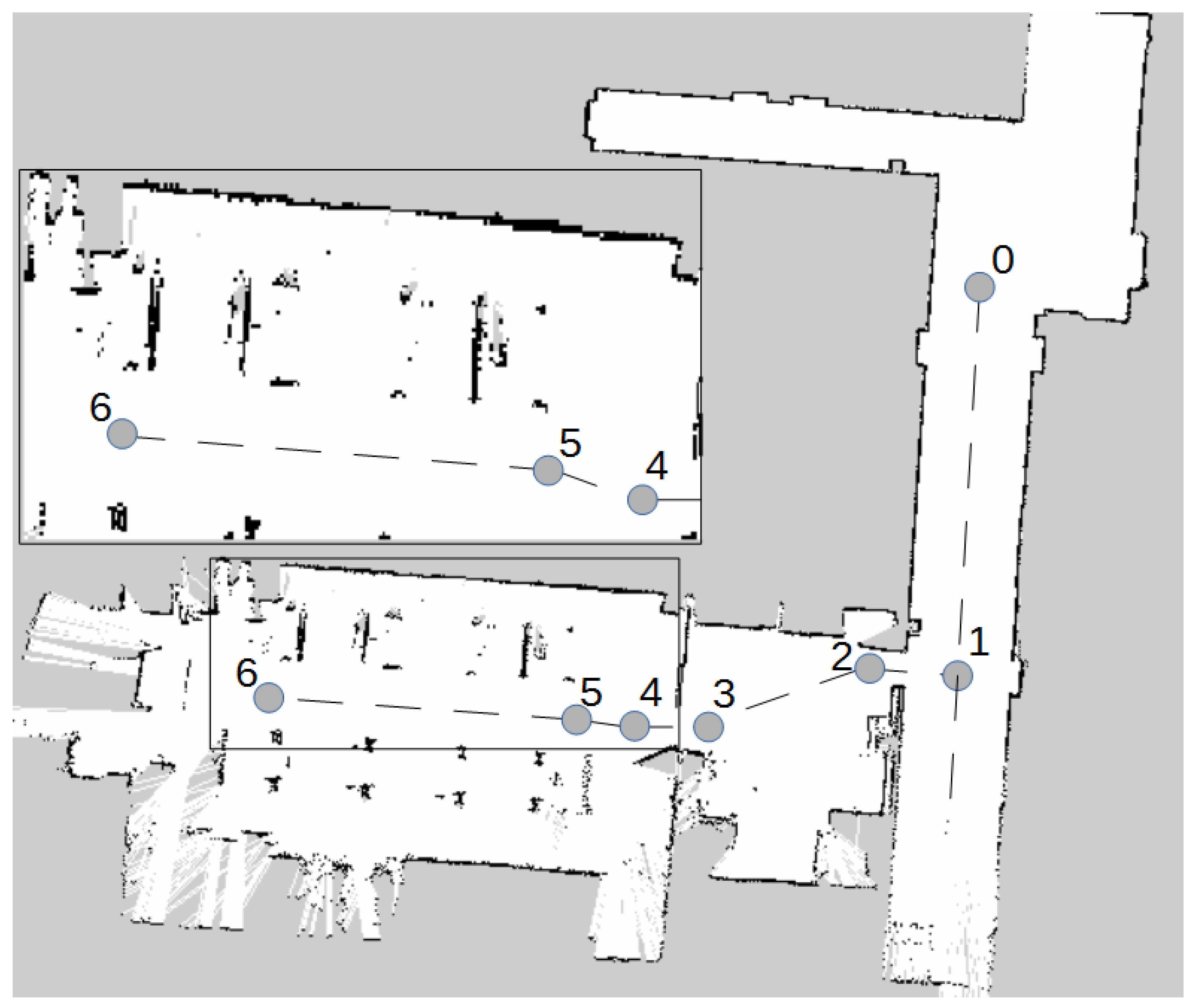
A visual description of the mission was preliminary presented in
Figure 4. For further precise discussion we will refer to
Figure 12. The mission starts with mapping the area and then defining the waypoints of the robot path, which include: mission start/end point (0), data recording start (5) and end (6) points. The remaining points (1, 2, 3, 4) are defined for the purpose of traveling to a specific location along the permitted area (
Figure 12). The total length of the planned path was 58.93 m.
The experiment area was mapped during a remotely controlled run. For the purpose of the laboratory experiments, area boundaries and obstacles were registered with a 2D LIDAR. After building the map, a path to be followed was defined. The path consisted of 13 waypoints (with a return path) and it was the same for all experiments. The waypoints were defined as robot positions and orientations to be reached and actions of the measurement subsystem to be executed after each waypoint is reached.
To verify the correct communication with the measurement system, the image data of the conveyor was recorded. From the industrial installations operation standpoint, it is important to compare current data with historical data. To allow for such a comparison, the recording of measurements is started and stopped at the same decision points. Two-way data exchange takes place between the robot controller and the sensor recording module. In order to be sure that the information was received, the confirmation of message delivery was used.
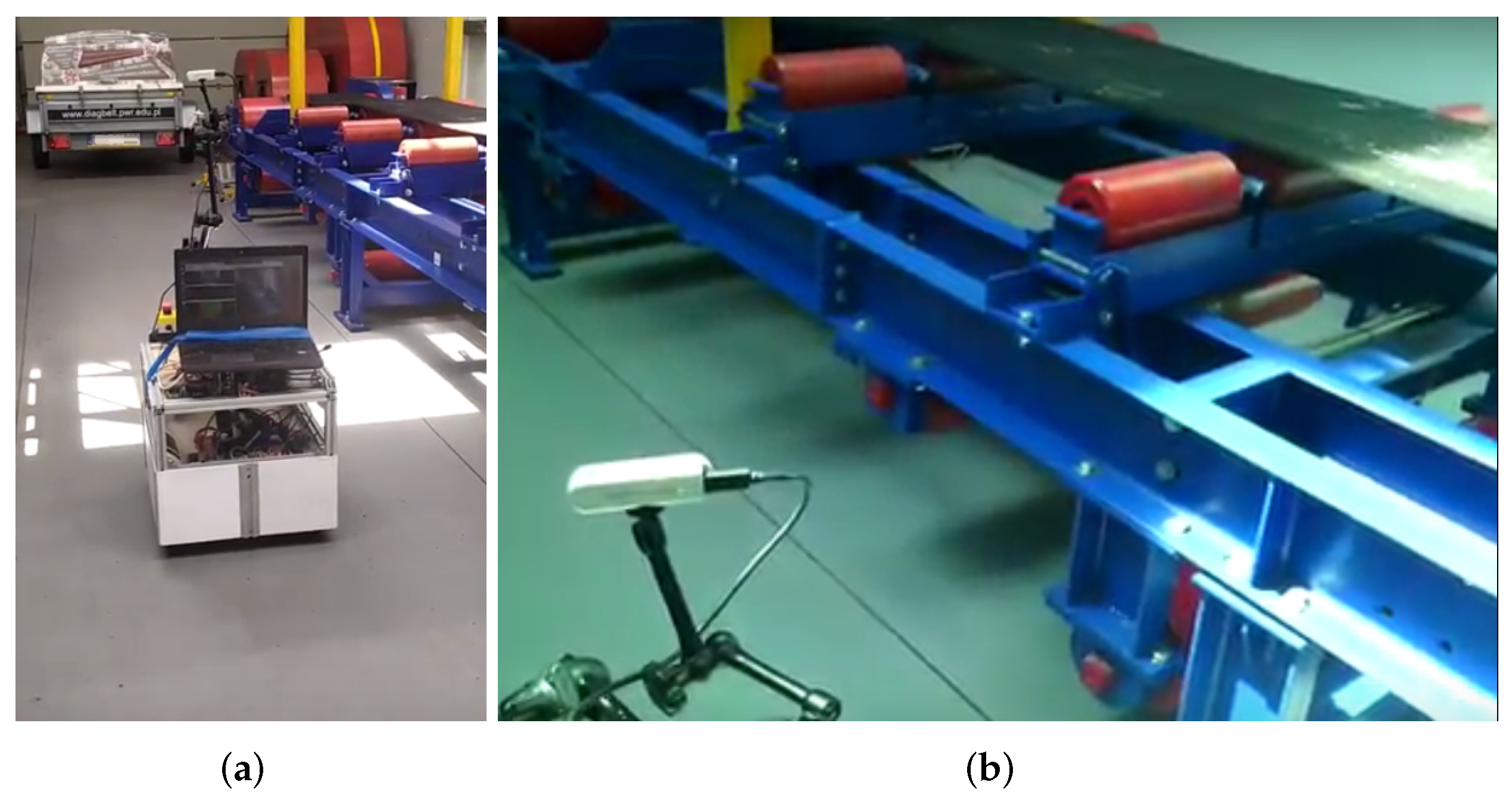
The experiment runs were repeated several times with two forward velocity limits. The view of the conveyor belt during the experiments is shown in
Figure 13.
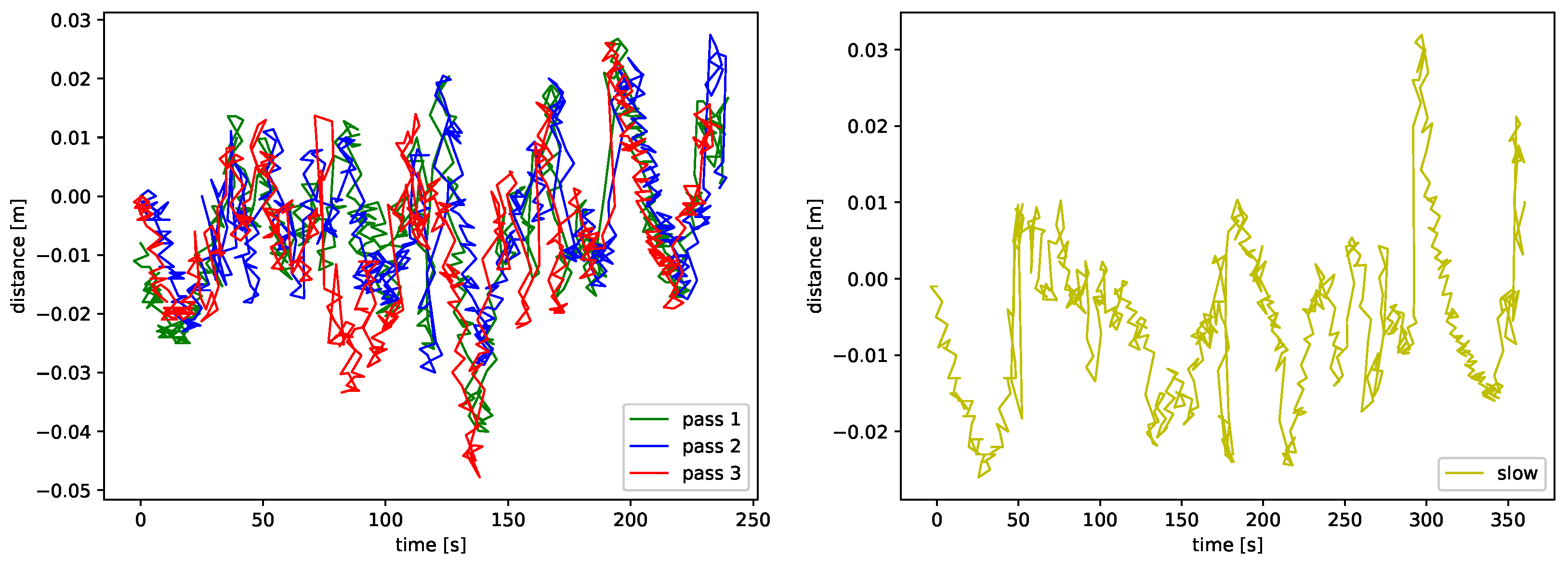
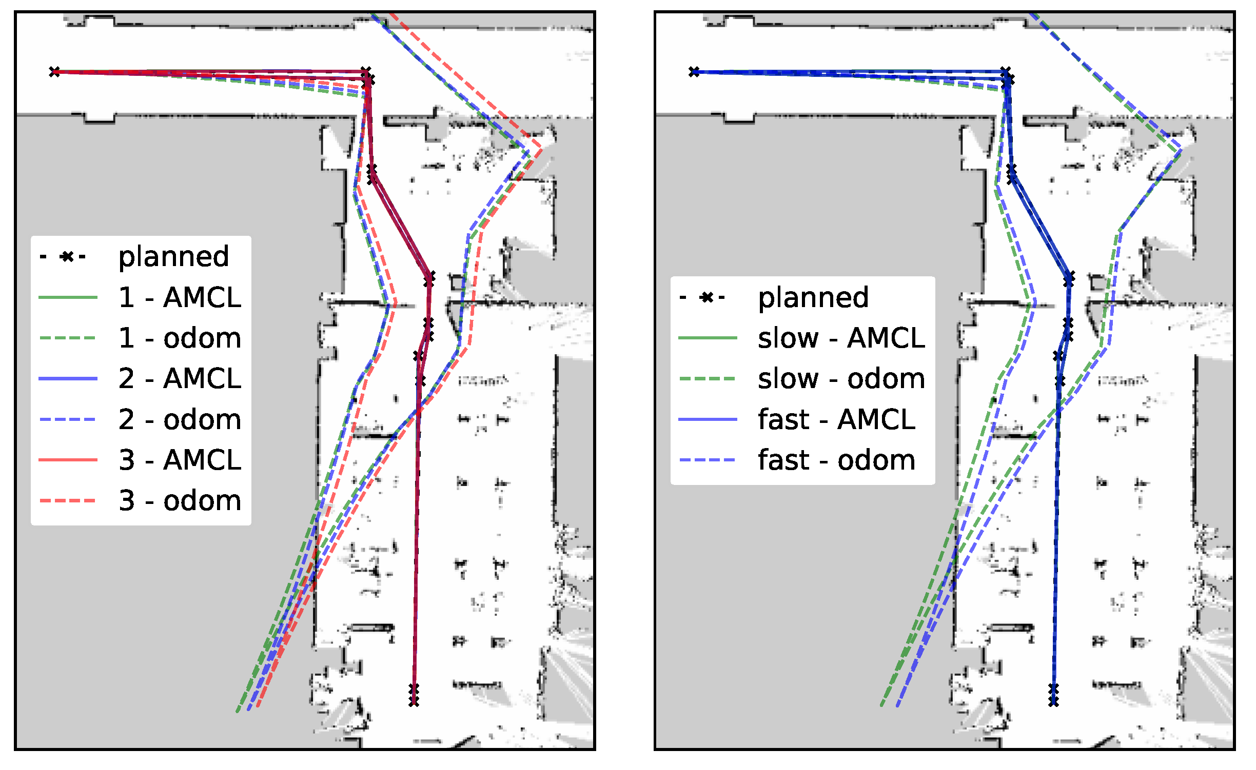
The experiment presented in this section included four full passes of the planned route, three of them, denoted below as “fast”, with a travel velocity set to 0.4 m/s, and one “slow”, with half of that value. During each pass all sensor data were recorded for further analysis of various aspects of the tested system. The localization data source for the autonomous drive was AMCL.
For the purpose of evaluation of the precision of path following, an instantaneous displacement between planned and executed paths was defined as a signed distance from the current robot position and a line connecting the current (
) and the preceding (
) waypoints as:
The time series plots in
Figure 14 present the results, separately for slow and fast passes. It can be observed that the displacement for the fast passes is slightly bigger, with the distance to the planned path reaching at the peak 0.05 m, whereas in the slow pass the maximum distance from the path did not exceed 0.03 m. However, for all experiments for most of the time the path did not drift from the plan by more than
m.
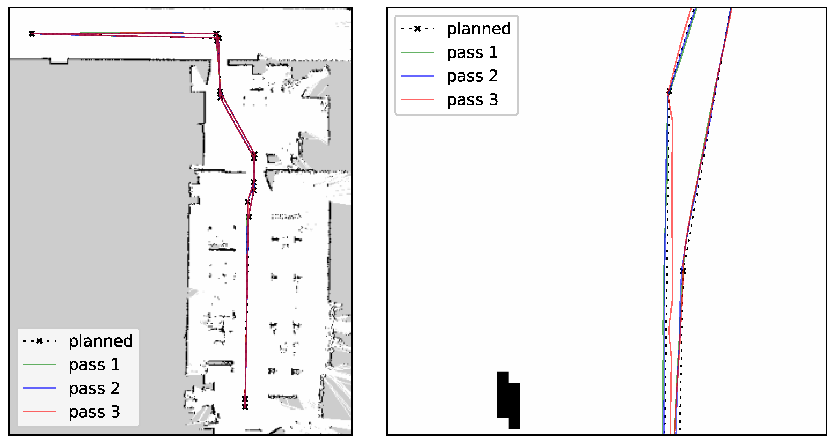
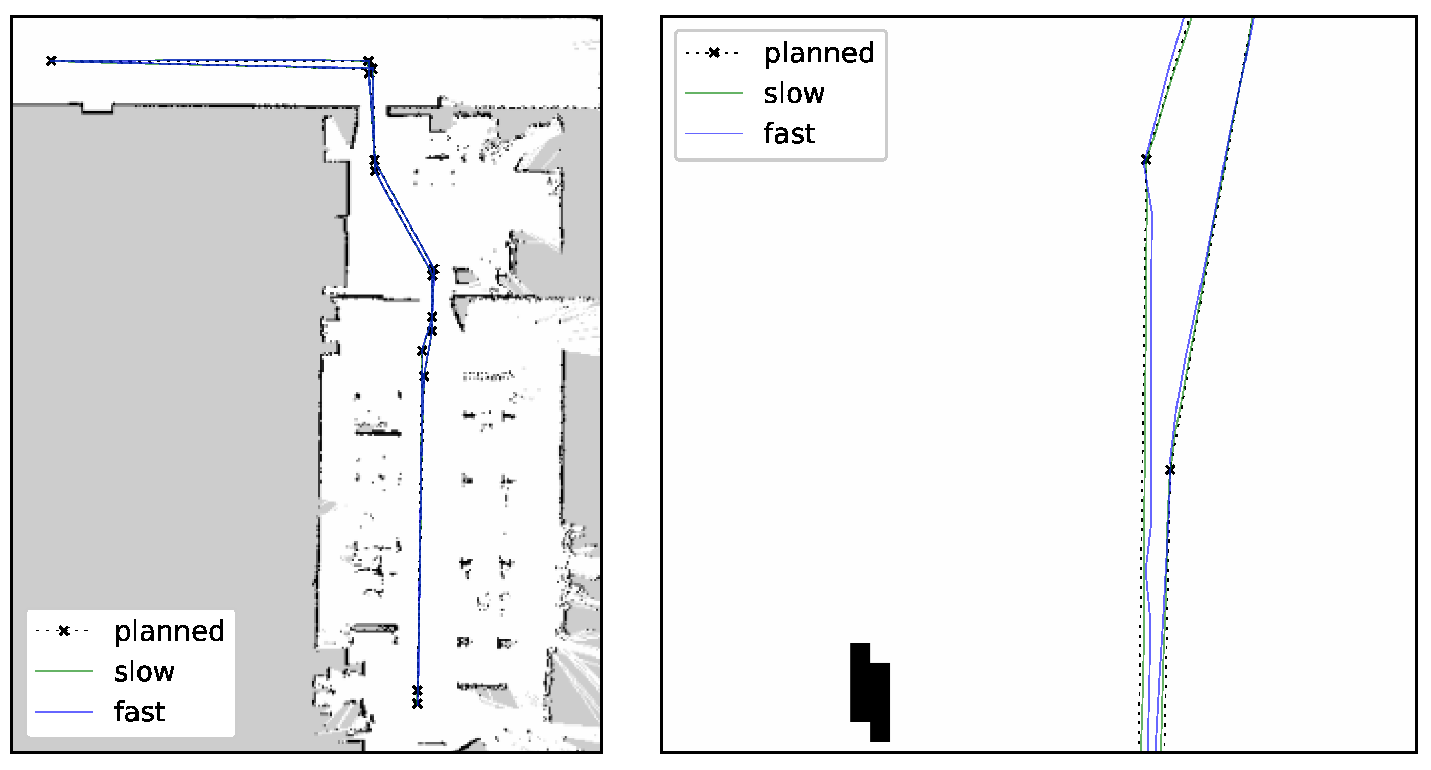
A visual comparison of “fast” paths with the planned path is presented in
Figure 15, while
Figure 16 shows an analogous comparison for the “slow” and one of the “fast” passes. One can observe that in both cases a difference between the paths from different passes is barely noticeable, even in a zoom view. That allows us to conclude that the paths are repeatable and that a reduction of velocity from 0.4 to 0.2 m/s did not significantly improve the quality of the path following.
The results for all tests show that the AMCL localization performed satisfactorily for the purpose of navigation. For a comparison, localization data from the odometry were calculated. The data from all passes are presented in
Figure 17. One can observe that the repeatability of the results is worse than in the AMCL case, but the main issue with the method is a big positioning error that disqualifies using odometry as a standalone method of localization for navigation.
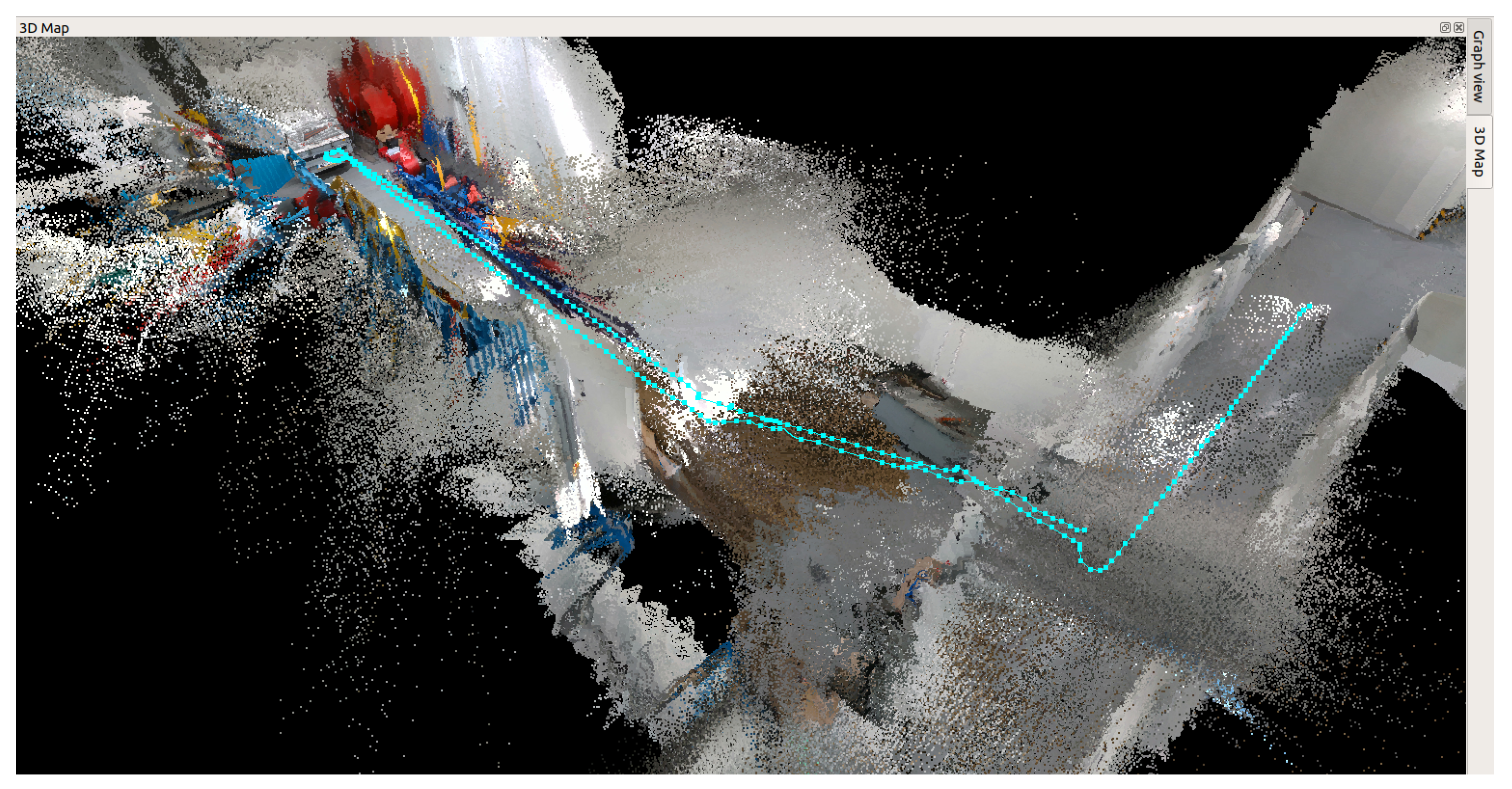
During the inspection drive, a 3D map was also recorded with the use of RTABMap [
46], which is presented in
Figure 18. The figure shows the visualization of the path traveled by the robot during the experiment in space.
5. Conclusions
The paper presents a proposition of an architecture of a system for automatic inspection of technical infrastructures such as belt conveyors, using a mobile robot platform and a procedure describing how to perform such inspections. The correct operation of the system was verified during experiments in a laboratory environment.
An automatic inspection is a complex task that requires several steps to be performed first to prepare and later to execute the inspection. In our system we have separated those two phases. The preparation phase contains environment mapping and inspection route definition, and it is carried out with the operator’s assistance. The execution part consists of following the route while collecting the measurements for further processing and is performed fully automatically.
The system was designed to navigate in areas where GPS localization is unavailable or unreliable. It is capable of building a map of the environment, self localization on the map, following a path along the user-defined waypoints and performing scheduled measurements along the movement. The system is built on an ROS framework. The area mapping in the preparation phase uses the Rao–Blackwellized particle filter SLAM and during the execution phase robot localization with the AMCL method is used.
The experiments in the laboratory were carried out in order to confirm that the system can execute the whole scheduled inspection route without an operator’s intervention. During the motion the drift of the executed paths from the plan and the other paths was observed. The tests were repeated several times with various velocities with two methods of robot localization: AMCL and odometry. The performed tests have shown that each time, the system with the AMCL localization was able to perform the whole inspection procedure correctly. Comparison of the paths followed by the robot has shown that the paths have high repeatability, which will allow direct comparison of measurements from different passes and relating recent data with historical measurements.
The results of the laboratory tests have proven the concept of the system. The next step of research is to move the tests to real conditions. That will require extending the current solution, which uses a 2D map, with the ability to move on rough (uneven) terrain, where either a full spatial map or multi-layer 2D maps will be needed.


