Modern Hybrid Excited Electric Machines


Faculty of Electrical Engineering, West Pomeranian University of Technology, Sikorskiego 37, 70-313 Szczecin, Poland
*
Author to whom correspondence should be addressed.
Energies 2020, 13(22), 5910; https://doi.org/10.3390/en13225910
Submission received: 1 October 2020
/
Revised: 27 October 2020
/
Accepted: 10 November 2020
/
Published: 12 November 2020
(This article belongs to the Special Issue Design and Application of Electrical Machines)
Abstract
:The paper deals with the overview of different designs of hybrid excited electrical machines, i.e., those with conventional permanent magnets excitation and additional DC-powered electromagnetic systems in the excitation circuit. The paper presents the most common topologies for this type of machines found in the literature—they were divided according to their electrical, mechanical and thermal properties. Against this background, the designs of hybrid excited machines that were the subject of scientific research of the authors are presented.
1. Introduction
Permanent magnets excited electrical machines, and in particular, hybrid excited, play nowadays an increasingly important role mainly due to their high efficiency and relatively high power-to-weight ratio. Their great popularity is related to dynamic developments in the field of modern materials, such as permanent magnets, magnetic composites, but also various types of power electronic components and fast and efficient microprocessor systems used to control the machine.
Over the past two decades, the development of technology has caused the properties of permanent magnets to improve rapidly. For this reason, permanent magnet machines have become competitive to those previously used.
Due to the development of machines of this type, manufacturers of various types of drive systems are increasingly turning to structures containing permanent magnets [1,2,3,4,5]. A very strong development in this area has been noticeable in the automotive industry. Currently, all major car companies offer cars powered by electric motors. Most of all, reliability and low production costs are required from motors in electric vehicles. Perhaps for this reason, until recently, the “strongest player” in this part of the automotive sector, which is the Tesla Company, used only induction motors in its designs. However, most manufacturers today use mainly permanent magnet motors [6].
Apart from the undoubted advantages mentioned earlier, permanent magnet machines have also some disadvantages. The disadvantages most frequently mentioned in the literature, include the higher cost of their production, compared to induction machines and limited and energy-costly ability to regulate the excitation flux. In variable speed drives, e.g., in electric vehicles, the drive is required to operate over the widest possible rpm range with the highest possible torque. Due to the constant flux of excitation from permanent magnets, to enable the motor to operate in the high-speed area—switching from constant torque to constant power characteristics—it is necessary to apply the d-axis current strategy [7]. This strategy is effective, but only to a limited extent. Too deep, field weakening can lead to permanent damage to the magnets, and also generates additional losses.
Another area by which electric machines, that can operate in a wide range of rotational speeds can be used, is wind energy that the electrical power that a wind turbine can generate depends on the strength of the wind. In the case of small (home) power plants, which usually do not have wind attack angle control systems on the turbine blades, the wind force will directly determine the rotational speed of the turbine, and therefore also the generator. There are several ways to regulate the rotational speed of a low-power wind turbine, from eccentric mounting of the turbine in relation to the axis of rotation of the entire nacelle, through more or less complicated mechanical systems causing the wind to press against the axis of rotation of the turbine, to electrical limiters (e.g., resistors) increasing the generator torque, which consequently brakes the turbine [8]. When a permanent magnet machine is used in a turbine of this type, the generation of energy depends on the occurrence of a minimum wind speed, as the generator voltage will be high enough to allow energy flow towards the receivers or energy storage systems.
In the above-mentioned areas (electric vehicle drives and generators in wind turbines), i.e., where it is necessary to regulate the excitation, rotational speed, induced voltage in the widest possible range and the efficiency of energy conversion is also important, electric machines with hybrid excitation can be successfully used.
The trend of minimizing the amount of permanent magnets in electric machines has been noticeable for many years. This is mainly due to economic aspects (PMs are relatively expensive), as well as limitations related to the temperature resistance, and permanent magnets may permanently lose their magnetic properties after exceeding a critical temperature. In addition, the development of electro-mobility forces, the use of electric machines with the widest possible range of rotational speed, at which the electric machine is able to generate the appropriate torque on the shaft. Otherwise, hybrid excitation allows for a much wider range of machine operation, compared to machines with only PM excitation. Research on hybrid-excited machines fits this trend perfectly, in which a part of the magnetic excitation flux is generated by the PM and the remainder by the corresponding electromagnetic system.
In this paper, in Section 2, the idea of controlled magnets is presented, and then in Section 3, an overview of the design solutions of hybrid-excited electric machines is presented. They are divided into several groups depending on the characteristic design properties. Then, based on this background, proprietary design solutions of hybrid excited machines are presented in Section 4, Section 5, Section 6 and Section 7, which are implemented at the Department of Power Engineering and Electric Drives of the West Pomeranian University of Technology in Szczecin. The paper ends with a short summary.
2. Controlled Magnets
The idea of hybrid excitation of electrical machines comes from so-called controlled magnets which were initially used in different levitation systems and magnetic bearings [9,10,11,12,13]. In these systems, strong permanent magnets are used for force generation. Their flux is modulated by currents flying in properly placed coils. The principle of operation of such a system is shown in Figure 1. It is equipped with additional current coils, which demagnetize one part of the magnetic circuit and magnetize the other one, depending on changes in the size of the air gap. In this way, the system is stabilized in the tangential direction having negative stiffness values. Figure 1 shows a situation in which the moving part of the system was horizontally shifted in relation to the neutral position. In this case, it is necessary to reduce the magnetic flux on the side of the smaller air gap and increase it on the opposite side, in order to create reverse forces moving the permanent magnet system back to the central position. The magnetic flux produced by the coil current is directed against the main flux on the left side of the system, and in line with it on the right side. The levitation force in the configuration shown in Figure 1 is generated by a large, strong permanent magnet, which guarantees the creation of high lift forces, and to actuate the bearing in the tangential direction, small currents in the electromagnets are required. This means that the entire system works with a very low power consumption by the system measurement and control and executive elements. The operation of all levitation systems requires the optimization of the magnetic field distribution within the air gap by means of proper choice of geometry, material characteristics and power supply conditions [14,15]. Controlled magnets are used in various levitation systems, and their most spectacular use tangential directions the Transrapid levitation and side stabilization systems [9,10,11,12,13].
Controlled magnets are the basic executive part of all magnetic bearings [16,17]. Figure 2 shows two examples of magnetic bearings: a conventional bearing with an external moving part and a hybrid bearing with the control coils placed in the stationary part of the bearing. Such bearings are stable in the axial direction, and the central position of the moving parts is maintained by appropriate control of the coils currents.
The mathematical description (voltage equations) of magnetic bearings is very similar to the description of hybrid-excited electric machines due to the appropriate selection of the coordinate system (rotating with the rotor). The main goal in magnetic bearings is to maintain a constant air gap, while in hybrid-excited machines, it is to obtain the required values of the magnetic flux.
3. Review of Hybrid Excited Machines
Hybrid excited electric machines can be divided into two groups. In the first group, the flux caused by the excitation winding passes through permanent magnets. The second group includes parallel excited hybrid machines. In these machines, the permanent magnet flux and the excitation winding flux have different trajectories. The magnetic permeability of PM is similar to air permeability. Therefore, for the first group machines, the coil magnetic reluctance is relatively high. This is a reason for the introduction of magnetic bridges into the machine in order to ensure lower reluctance for the excitation circuit.
For all machines with hybrid excitation the general mathematical model is described by Equations (1) and (2). They show that the induced voltage and magnetic flux related to the machine axes d and q – and, consequently, to the electromagnetic torque depend on the flux from permanent magnets and the current in the excitation coil [18,19]. Information about transformation from three-phase (L1–L2–L3) system to two phase (α–β) system, and then to d–q axis, are described in details e.g., in [20],
where ud—d-axis voltage component, uq—q-axis voltage component, uc—voltage on the excitation coil, Rs—stator winding resistance, s—operator d/dt, Ld—d-axis inductance, ωe—angular velocity, Lq—q-axis inductance, Msc—mutual inductance between the stator winding and the excitation coil, Rc—excitation coil resistance, Lc—inductance of the excitation coil, id—d-axis stator current component, iq—q-axis stator current component, ic—excitation coil current, ΨPM—flux of permanent magnets,
where: Ψd—d-axis flux, Ψq—q-axis flux.
The comparison of different structures of hybrid excited electrical machines is very difficult because of their variety. They can be compared, e.g., in terms of their external characteristics (mechanical design) [1,2,3,21]. Hybrid excited electrical machines can also be categorized according to the path-determining design of the combined excitation flux. There is a huge number of design solutions for hybrid excited machines. This Chapter presents the most interesting ones found in the literature.
3.1. Synchronous Machines with Permanent Magnets
In order to regulate the excitation flux, in addition to permanent magnets, an additional source is used in the form of a winding. A different approach is presented [22]. The synchronous generator rotor has been modified by adding permanent magnets. In this way, it became independent to some extent from the failure of the sensitive part of the machine, which is the arrangement of brushes and slip rings. The machine can operate at high rotational speed with weakened excitation field. There is a high flux density between two adjacent PM poles, which can increase iron losses in the stator core.
3.2. Flux-Switching Machines
A novel hybrid excitation flux-switching motor (HEFS) presented in [25] is dedicated to hybrid vehicles. A new motor topology has been proposed, in which the dimensions of the magnets have been reduced to save space for additional excitation winding, while the rotor and stator lamination remain unchanged. It should be noted that this allows the machine stream to be adjusted by controlling the length of the magnets in the radial direction. This solution in its idea is to eliminate the disadvantages, even higher torque ripple due to the cogging torque, which has, for example, a permanent magnet motor with flux switching (FSPM). Similar design has been investigated in [26]. The paper presents numerical research as well as experimental tests on built machine prototype.
3.3. Doubly Salient Machines
The paper [27] presents design of hybrid excited doubly salient machine with parallel excitation system. Authors of the paper analyzed the regulation possibility of air gap flux in three types of the machine main poles. By performing simulation and then experimental tests, obtain very good control properties from approx. 30 V to approx. 220 V. Hybrid excited doubly salient machines are also presented in [28,29,30].
3.4. Axial Flux Machines
The text [31] discusses a synchronous, hybrid excitation, axial flux generator in autonomous mode, with a field winding powered by an armature winding. The proposed solution allows for very precise control of the magnetic flux, which allows to obtain the set value of the output voltage in cases where the load or speed changes, or both. Very interesting designs of hybrid excited axial flux machines are also described in various papers [32,33,34,35].
3.5. Axial-Radial Flux Machines
Structural optimization, which maximizes the flux control range of a dual excitation synchronous machine, is discussed in the paper [36]. The air gap flux in this type of machine can be regulated by controlling the field currents. A machine of this type is able to regulate the air gap flow more flexibly compared to conventional PM machines. This has been achieved at the expense of more volume and higher costs due to the presence of additional field windings. Both electromagnetic and thermal complexity has been well addressed through the use of equivalent circuit networks. It was also found that one of the analyzed configurations almost eliminates the PM flux. Similar construction of the machine is shown in [37]. On the other hand, in [38] the authors presented simulation studies of a machine with an excitation flux in both, radial and axial direction, while the rotor is similar to a rotor of a flux-switching machine. In addition, some parts of the machine are proposed to be made of SMC material.
3.6. Dual Rotor/Stator Machines
In [39], a new toroidal winding twin-rotor permanent magnet synchronous reluctance machine (PM-SynRM) is discussed, which is proposed for high electromagnetic torque taking full advantage of the permanent magnet torque and reluctance torque due to the special design of the mounting angles of the two rotors. Permanent magnet torque and reluctance torque of the proposed machine can obtain their maximum values near the same current phase angle due to the special configuration of the two rotors, which significantly increases the total torque. It turned out that, as a result of the FEM analysis, the proposed machine gives much better torque results. On the other hand, the proposed double rotor structure has excellent properties and resistance to irreversible magnetization. The paper [40] discusses the research on a hybrid excited machine with a double rotor, in which one part is a rotor with permanent magnets, and the other—a classic wound rotor.
Inverted structure is presented by the authors of the paper [41]. In the paper, a hybrid-excited PM machine, based on the flux modulation effect, has been proposed. The authors state that in the machine there is no risk of irreversible demagnetization of PMs. Moreover, the machine does not need slip rings and brushes, since the DC excitation coils are placed in the stator, which makes the structure simple and reliable. The paper shows FEA numerical model of the machine, its structure and the working principle. Similar design is presented in [42].
A very interesting, but at the same time very complicated structure, was presented by the authors [43]. The paper presents a machine with two stators (inner and outer) and two parts of the rotor, one of which was composed of alternately arranged N and S magnets, and the other part was a classic claw pole rotor with excitation from the coil inside it.
3.7. Hybrid Excited Machines with DC Winding on Stator
The concept of a machine with hybrid excitation with permanent magnets and excitation of the AC field winding is presented in [44]. In this machine, permanent magnets (PM) are placed on the rotor side and the AC windings on the stator side for flux control while ensuring high torque. Since the magnetic field PM rotates with the rotor, the alternating currents would have the same frequency as the motor speed. The obtained results and FEM analyzes show that, in the case of the HEPM machine, flux regulation and operation in a wide speed range can be realized, and the electrical parameters can be improved compared to the original IPMSM, which could verify the theoretical analysis presented above, expand the method of designing permanent magnet machines and control strategy and provide a reference to the design of machines with hybrid excitation of permanent magnets.
Similar design can be found in [45]. An example of a parallel hybrid excitation machine is hybrid excitation flux reversal machine (HEFRM). It has been designed for application in electric vehicles propulsion. It may not only show better overload and the possibility of weakening the flux, but also reduces the risk of PM demagnetization. The change in the air gap flux can be controlled by controlling the excitation winding current, which also improves the overload torque at low speeds.
3.8. Axial Flux SRM Machines
The issues of construction and modeling of a machine with some favorable features for wind energy conversion applications are presented in [46]. A machine with a double stator with an axial rotor and permanent magnet flux switching (AFSPM) was adopted for consideration. The developed model of this machine was verified by comparing its results with the results from the two-dimensional (2D) FEM model. The modeling approach adopted has proved to be effective and gives good results compared to FEM. The open-circuit AFSPM performance was compared to the previously developed SMPMAF prototype. This comparative study showed that the EMF waveform is very close to the sinusoidal signal for AFSPM, which is desirable for the intended applications. However, for SMPMAF the EMF wave contains more harmonics.
3.9. Consequent-Pole Permanent Magnet Machines
An innovative concept of a permanent magnet motor with sequence poles was proposed in [47]. The motor has a unique rotor configuration in which the actual PM pole pairs and image pole pairs are positioned every other pole pair. The pole pairs of the image are formed on parts of the iron core next to the actual solid parts of the rotor surface. One of the most important features of the proposed motor is the ability to run at high speed with a lower field-weakening current (negative d-axis current). This enables the operating range to be effectively extended at high speeds without increasing copper losses. One disadvantage is that the amount of effective magnetic flux is too low, which results in a lower torque in the low speed range. Therefore, optimization of the magnetic circuit is needed.
A slightly different construction is presented in [48]. The subject of the research was a machine, the rotor of which had alternating permanent magnets and iron poles, consequently one pole of the machine was a magnet and iron element. Between the two parts of the stator the excitation regulating coil was placed.
3.10. Claw Pole Machines
The rapid development of hybrid vehicles has prompted the need to develop a highly efficient source of electricity for this type of vehicle. One of the ways to achieve this goal is to equip the synchronous generator with claw poles.
The article [49] proposes a new design of a machine with a claw pole and compares its performance with a conventional machine. The new design features permanent magnets in the inter-claw region to reduce leakage flux and provide increased magnetic flux in the machine. It was observed that when adding permanent magnets weighing only a few grams, the machine output power increased significantly by over 22%. The geometrical dimensions of the magnets were also changed to verify their influence on the operation and it was observed that, as the mass of the magnet increases, there is a non-linear increase in the machine torque. The power-to-weight ratio of the machine has also been significantly improved, which is one of the main advantages for mild hybrid applications.
A similar variant of the rotor structure, only seven-phase, was considered in [50]. This solution is characterized by an unequal number of pairs of magnetic poles between the armature and the excitation circuit. In this case, it is necessary to model only a quarter of the structure, not a third as in the case of a classical generator, where the number of bars of the rotor and stator poles is the same p = 6. The main goal of the project was to increase the output power and reduce the core losses.
The paper [51] presents a hybrid excited machine, in which the sources of the excitation field are placed inside a claw rotor—toroidal permanent magnets are inside the toroidal core, on which the excitation coil is located.
4. Electric Controlled Permanent Magnet Synchronous Machine
Electric Controlled Permanent Magnet Synchronous machine (ECPMS-machine) is one of the hybrid excited machine concepts with good application prospects. The magnetic field excited by the DC coil current (IDC) gives possibility to change a machine air gap flux and consequently the stator flux linkage Ψs. In this way, the output voltage of the machine is electrically controlled.
Figure 3 shows ECPMS-machine concept, in which an air gap flux is controlled by a DC excitation control coil (DC control coil), fixed on the stator or on the machine rotor. The presented 12-poles ECPMS-machine design has a winded double stator, which is separated by a stator DC control coil and is centrally placed between two stator laminations. The stator DC control coil is locked inside a toroidally-wound additional stator core. The machine rotor has two lamination stacks which are separated by toroidally-wound additional rotor core. The rotor lamination structure has multi-flux barriers and embedded flat magnets NdFeB type, that form six iron poles (IP) and six permanent magnets poles (PMP) for each of two rotor stacks. The main feature of the proposed rotor structure is related with proper machine air gap flux distribution and simultaneously required machine flux control (FC) ability. The presented ECPMS-machine concept has been presented in [7,52,53,54].
4.1. Stator DC Control Coil of the ECPMS-Machine Concept
The concept of hybrid excitation with permanent magnets and the additional DC field winding locked on the stator machine is presented in Figure 4. The DC control coil placed on the stator side (Figure 4a) is used to control the machine air gap flux. The presented machine design concept has been widely analyzed in [52], where the influence of rotor structures on field regulation capability of the machine has been described. The main results of the study show a rotor structure which ensures the effective machine flux regulation. The results obtained during FEA carried out on the three-dimensional (3D) model of the machine (Figure 4b, where B is flux density expressed in tesla) confirmed effective flux control of the machine. The characteristics of magnetic flux linkage Ψs versus of DC coil magneto-motive force (MMF) θDC, which can be seen in the Figure 4c, is proof.
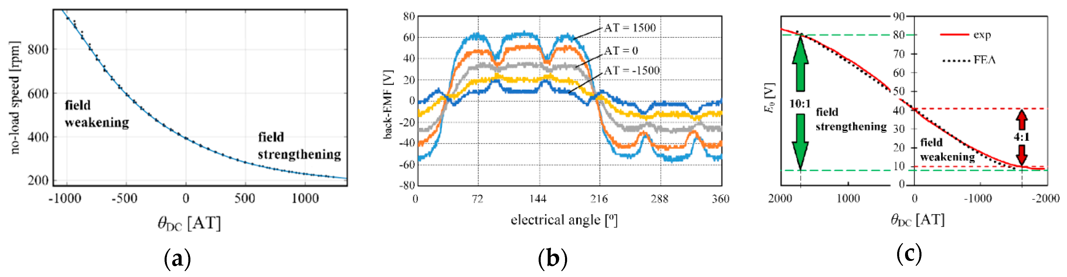
To validate the simulation results, a set of experimental tests have been carried out on a machine prototype. Figure 5 shows experimental validation results of no-load rotor speed obtained at constant DC-bus voltage of 100 V (Figure 5a), back-EMF waveforms recorded at 1000 rpm rotor speed (Figure 5b) and characteristics of no-load induced voltage in phase winding (Figure 5c) at different DC coil MMF of ECPMS-machine. The results have shown that the high (10:1) field control ratio of the presented hybrid excited machine concept is successfully achieved.
4.2. Rotor DC Control Coil of the ECPMS-Machine Concept
The DC excitation source can be placed in the rotor of ECPMS-machine. Figure 6a presents a 3D-FE model and rotor prototype of the machine where the placement of the DC control coil on the rotor is clearly shown. It should be noted that, depending of the presence of the stator DC control coil, the rotor DC control coil can be an additional or independent source of excitation.
Commonly, in order to supply the windings placed on the rotor, it is necessary to use brushes and slip rings. Alternatively to this, modern contactless energy transfer (CET) system shown in Figure 6b have been performed and described in [54], and it has been successfully used, in this case.
Figure 6b shows construction details of the ECPMS-machine prototype with the rotor DC control coil and supply coils used for the wireless power transfer which have been designed and locked on the housing of the machine prototype. Such a solution includes a transformer whose windings are formed by a double-sided printed circuit board (PCB) (used 70 µm copper thickness) plates. On both parts of the secondary and primary plates, ferrite sheets have been used as the path of the magnetic flux (Wurth Electronic® WE-FSFS flexible ferrite sheet, number 344,003). Air gap between TX and RX-coil was approx. 1 mm, in this case.
Figure 6c shows experimental results of phase back-EMF waveforms recorded at constant rotor speed of 1000 rpm by three operating conditions at rotor DC control coil MMF (0 and ± 1000 AT). The results show that the field control ratio (FCR) up to 4:1 can be effectively obtained. Additionally, the result of FWR has been achieved at low losses and low power consumption of the rotor DC control coil. In this case, the power consumption of the DC control coil (at 1000 AT excitation) is approx. 20 W.
4.3. ECPMS-Machine Concept-Conclusion
The presented ECPMS-machine belongs to the concept of hybrid excited machines with excellent field-control capability, which can be used in wide adjustable speed drives. The experiment validations have shown that the field control ratio 10:1 of the presented machine can be effectively obtained. This property can be used in electric vehicle drives and other adjustable speed drive applications.
Advantages: wide flux control range, high starting torque, totally flux-weakening possibility, low demagnetization risk of rotor magnets, possibility to locate additional DC field sources on the stator or rotor machine, or both.
Drawbacks: additional components, complex machine structure and greater weight and dimensions compared to conventional machines.
5. Hybrid Excited Disk Type Machine
The hybrid-excited axial flux machine (HEAFM) is built on the basis of an internal double winding stator and two external 12-pole rotors connected by a ferromagnetic bushing. Additional electromagnetic excitation is placed in the stator circuit. The structure of the machine is shown in Figure 7.
The machine’s stator is made of two laminated toroidal cores, and in each of them 32 slots with a 3-phase winding. The DC coil used as an additional excitation source was mounted on the inside of the stator around the rotor bushing. The coil is stationary, so it has no brushes or slip rings. The rotor consists of two outer discs connected by a steel sleeve. On each disk are alternately mounted iron poles with magnets polarized in one direction. There are 6 pole pairs on each disc. The operating principle of HEAFM is shown in Figure 8. When no current flows through the DC coil, the main magnetic flux in the machine flows through the air gap between the magnets, and part of it between the magnet and the iron pole. Depending on the direction of the current in the DC coil, the iron poles magnetize, which in turn leads to a strengthening of the main flux (FS) or its weakening (FW).
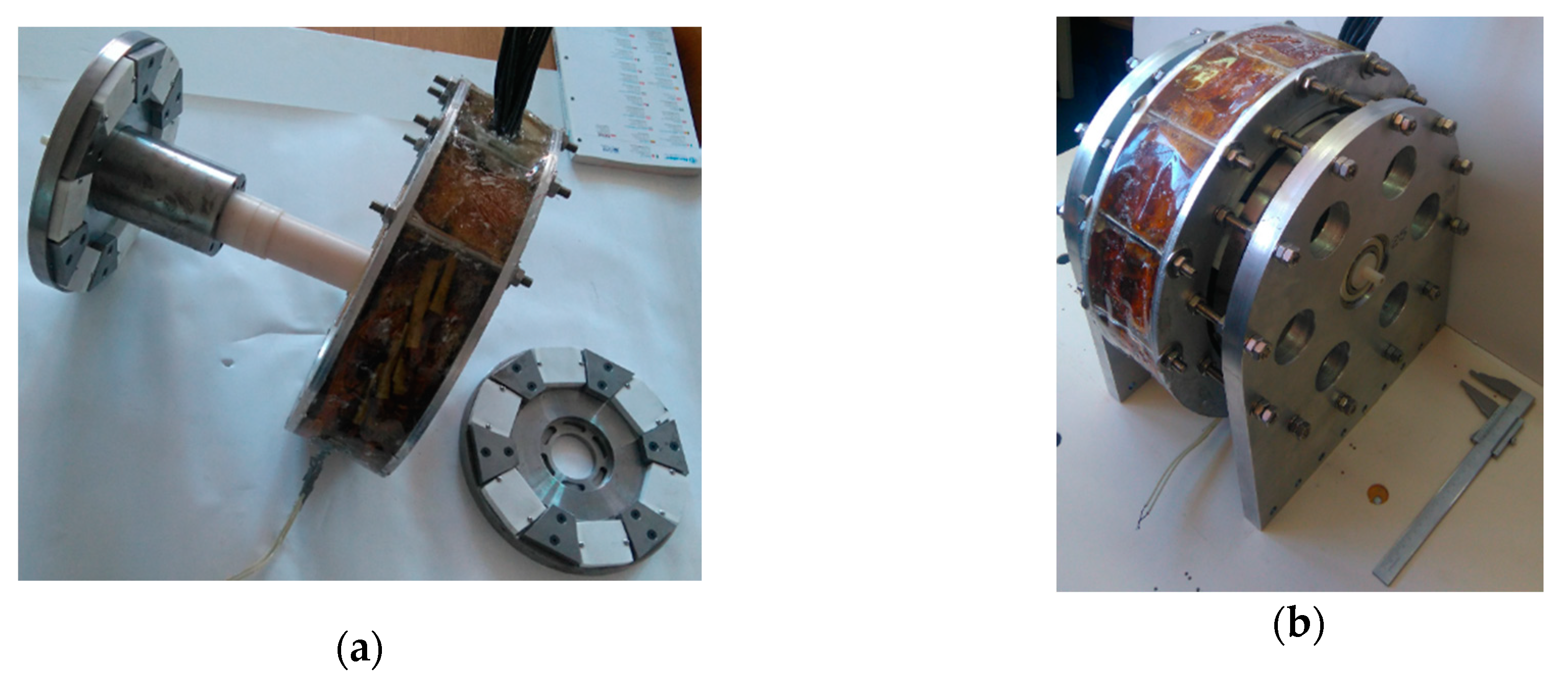
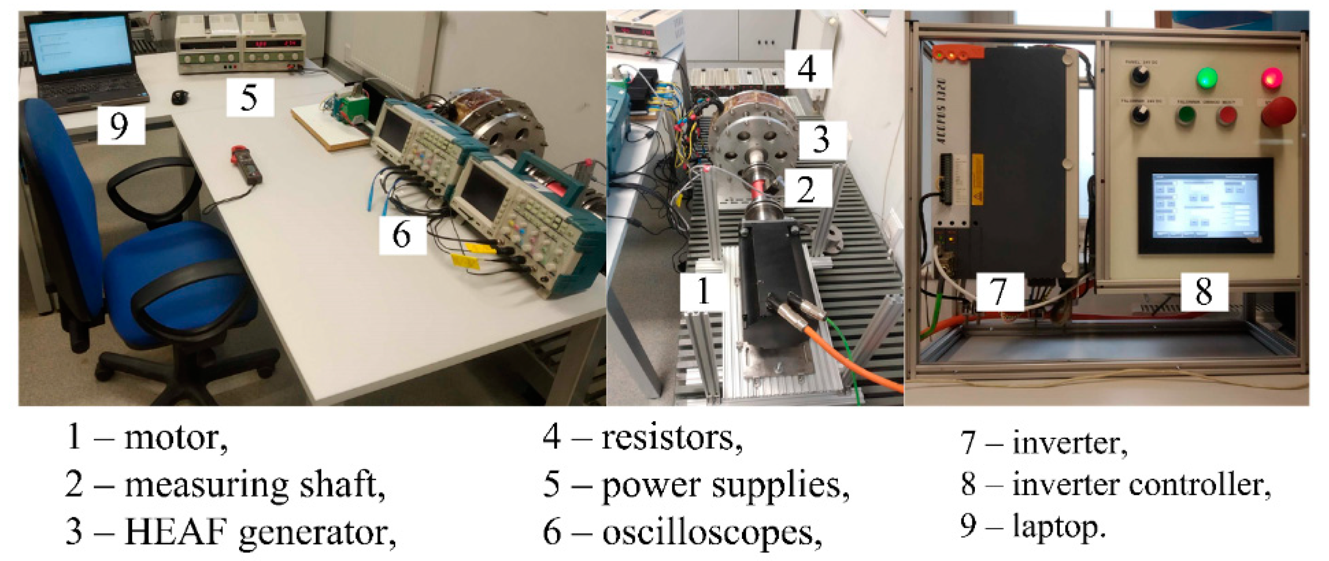
The prototype of the machine (Figure 9) was made in accordance with the assumptions and tested on the experimental stand (Figure 10) in generator mode.
Waveforms induced in the machine without load at a speed of 600 rpm for different currents in the DC coil are shown in Figure 11 by a dotted line.
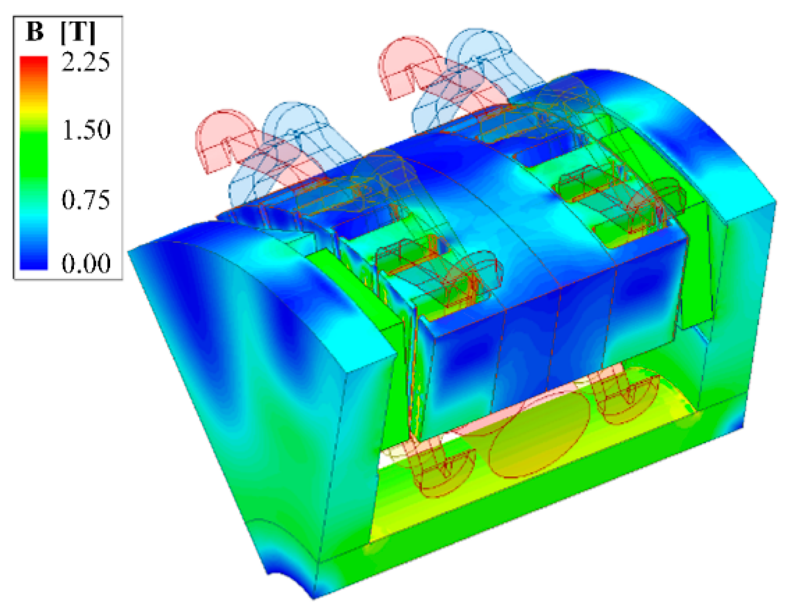
A 3D model of HEAFM was built and simulations were made using the finite element method (FEM). Figure 12 shows the distribution of magnetic induction in a magnetic circuit of the machine with the unpowered DC coil. Figure 13 shows the 2-D distribution of magnetic induction in an air gap for different currents in the DC coil on an arc, the radius of which is the average of the inner and outer radius of the machine active parts. This arc spans two adjacent poles: iron pole and PM pole.
The results show that the magnetic flux only changes under the iron pole, which is the advantage of this design, unfortunately the FS level is much higher than FW. Waveforms of magnetic induction in air gap for different currents in the DC coil are shown in Figure 13.
Subsequent simulation studies were to show the effect of modification of the machine’s magnetic core on the magnetic field regulation (FCR) range. The height of the magnets was examined first. The base model was the machine in which the height of PM was 12 mm and it was changed in the range from 2 to 14 mm. ΔFCR is the ratio of the base machine FCR to the FCR of the machine with different heights of PM (Figure 14).
The results show that the amount of PM has an impact on FCR. With increasing PM height, the induced voltage increases, but at the same time the possibility of its regulation decreases.
Further research aimed to demonstrate the impact of permanent magnet materials on FCR. For this purpose, various types of PM were shown, shown in Table 1.
FEM simulations have been conducted for no-load generator mode. Table 2 shows the distribution of induction throughout the entire air gap and the percentage ratio of magnetic flux flowing through the surface over the iron pole (IP) to pole with permanent magnet (PMP).
The waveforms of induced voltages for selected materials of PM—neodymium (N38H) and ferrite (F30) depending on the currents in the additional DC coil at 200 rpm are also presented in Figure 15.
Based on the simulating results, which was made, it can be concluded that despite the N38H magnet is the strongest and has the largest coefficient kΦ%, it allows the smallest possibility of flux control, and thus the induced voltage regulation.
The FCR coefficient of the analyzed machine is influenced, among other factors, by the magnetic circuit topology, including the shape, dimension and material of PM.
6. Hybrid Excited Claw Pole Machine (HECPM)
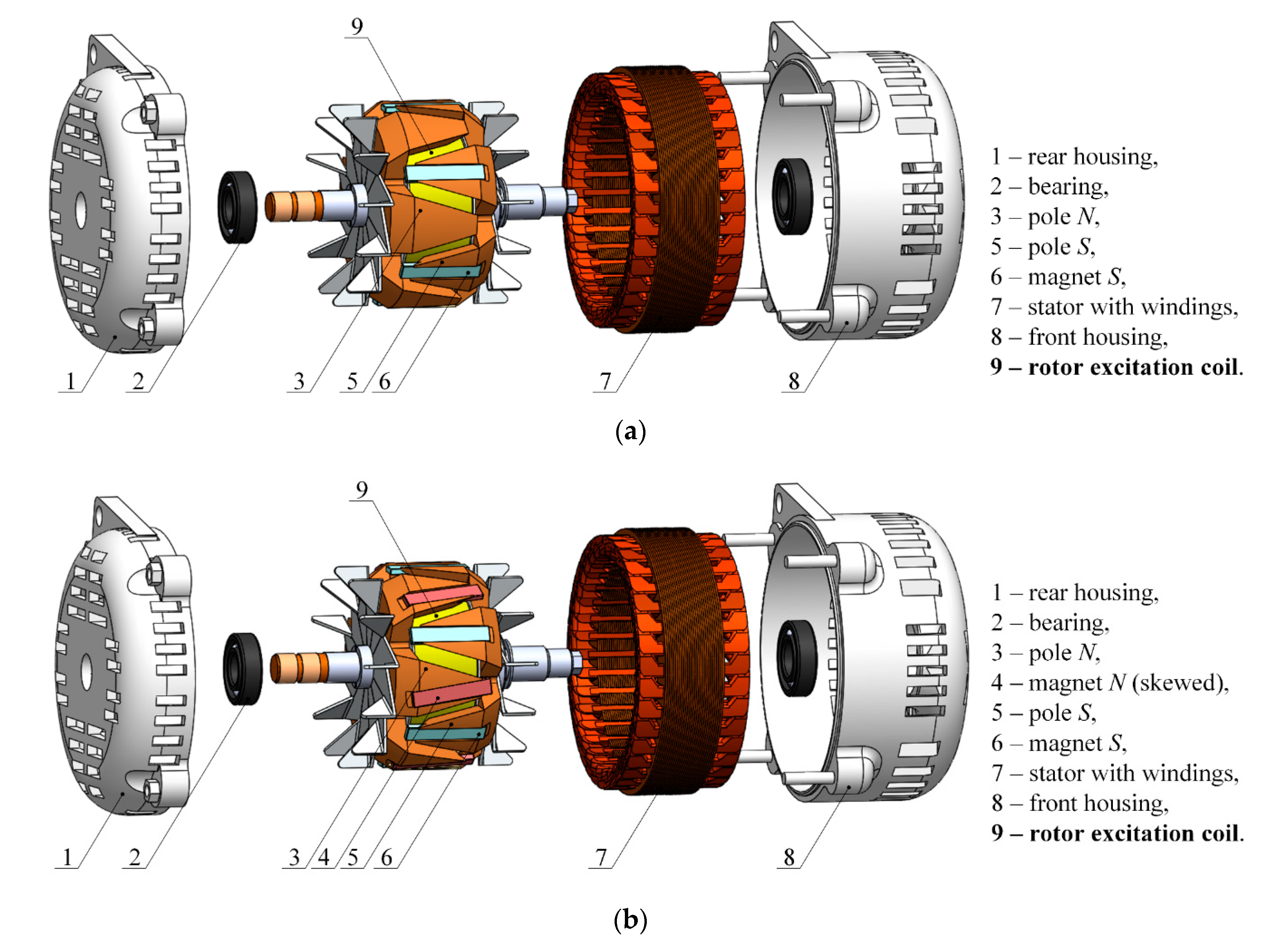
One of the innovative solutions is the use of hybrid excitation in claw pole machines by placing permanent magnets on or inside the claws. A construction of a hybrid excited claw machine with permanent magnets placed in milled areas on one [56] or both parts [57] of the rotor was proposed. Figure 16 shows these structures.
During the scientific research of the proposed solutions, in order to experimentally validate the results of numerical tests, a car alternator manufactured by Denso, with the nominal current In = 100 A and nominal voltage Un = 12 V, was used and rebuilt, while maintaining the standard excitation regulator. As a result of the work, it was possible to develop a technical solution that made it possible to self-excite the machine without the use of an additional DC source. In the first solution [56], self-excitation took place at the rotational speed equal to 1300 rpm, while in the second solution [57]—at 850 rpm. This feature can be used in a home wind turbine—in the absence of wind, thanks to the use of one diode, the generator regulator would not get energy from the batteries, while when the wind of sufficient strength appears, the generator would be self-excited, and consequently the energy would be generated for the storage system.
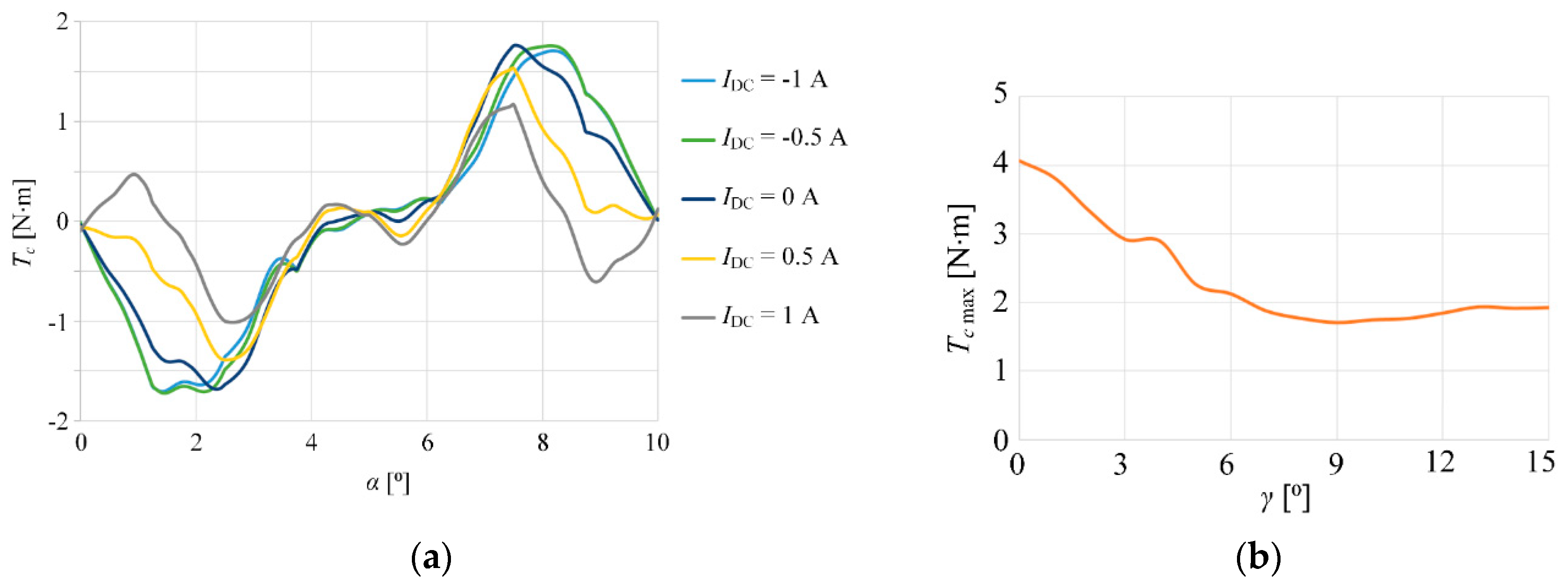
The influence of the excitation current on the cogging torque of the machines was also investigated. The results are shown in Figure 17a which shows cogging torque waveforms for a machine with permanent magnets on one part of the rotor for five current values in the excitation coil-parameter α is an angular (mechanical angle) position between rotor and stator.
In the second model, the magnets from the first model (on one part of the rotor) were retained and another 6 magnets were added to the second part of the rotor, however, simulation studies on the influence of the γ angle between the permanent magnets on this part of the rotor and the machine axis were previously carried out with using FEA. This angle varied from 0 to 15° in steps of 1°. It turned out that the angle at which the lowest cogging moment occurs is γ = 9°. The chosen results are presented in Figure 17b, which demonstrates the maximum values of the cogging torque as a function of the angle γ, in a no-load excitation coil state.
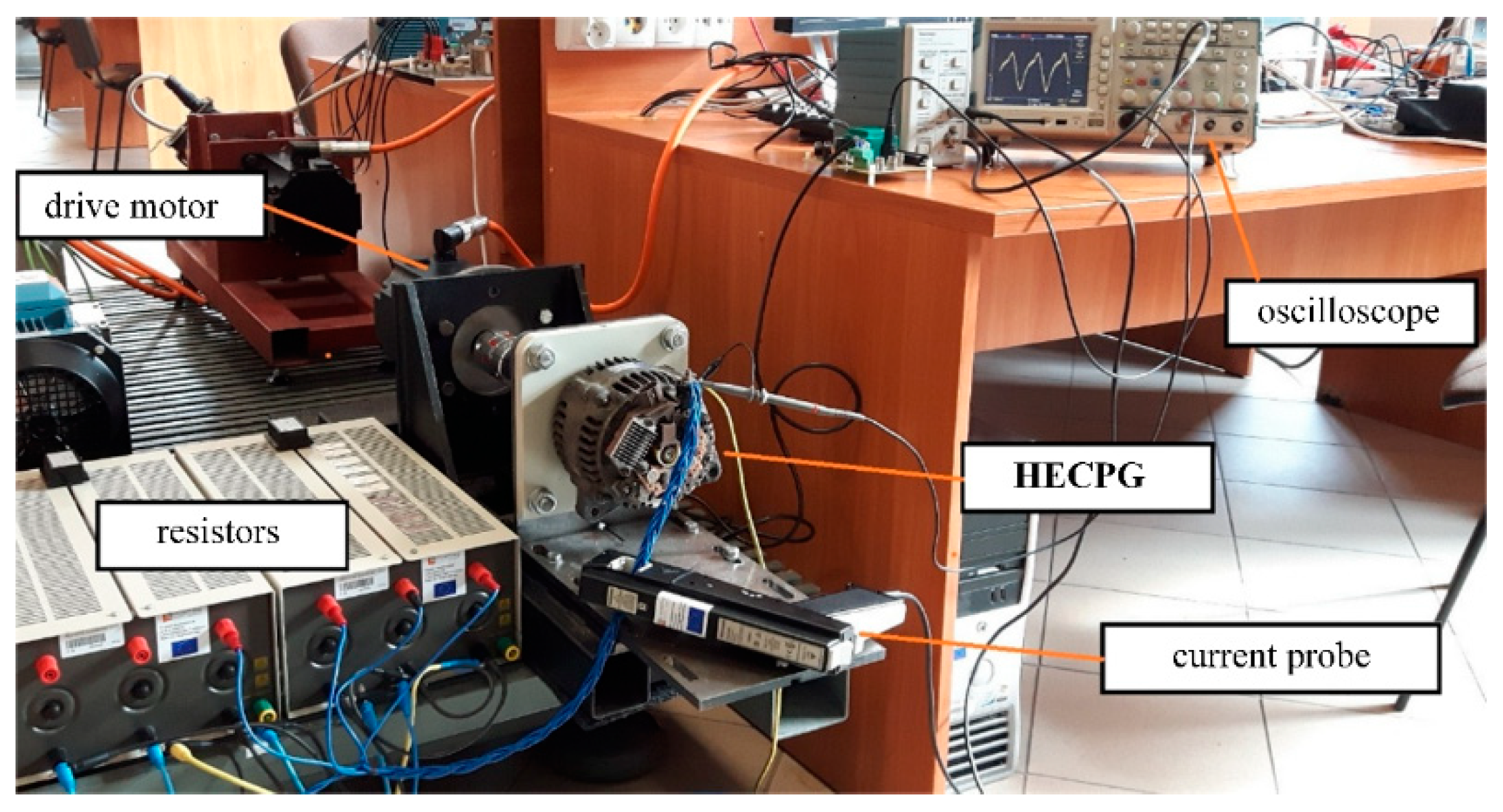
The test results showed that the induced voltage decreased with the increase of the angle γ, while the cogging torque reached the minimum for the angle γ = 9°. Additionally—thanks to the use of additional magnets set at an angle of γ = 9°—the machine was self-excited at speeds up to 450 rpm lower, moreover, despite the fact that twice as many sources of magnetomotive forces were installed, the cogging torque in the no-load state of the excitation coil did not increase in relation to the machine presented in [57]. Figure 18 presents experimental stand with HECPM.
Very important, from the technological point of view, is the simplicity and ease of production of all kinds of devices, including electromechanical energy converters. For this reason, a new approach to designing a hybrid excited claw machine has been proposed. The paper [58] presents the concept of building a machine with the use of a laminated rotor made by sheets of an appropriate shape (Hybrid Excited Claw Pole Machine with Laminated Rotor—HECPMLR). Figure 19 shows FEA model of the tested HECPMLR machine which is 1/6 of whole machine.
This type of approach allows the construction of even the most complex electromagnetic structures. The paper [58] presents also preliminary results of simulation tests of the proposed structure and the relationship between the maximum cogging torque and the induced voltage distribution depending on the current in the excitation coil (Figure 20). Figure 20a shows the maximum value of the cogging torque Temax depending on the current in the excitation coil Iexc, and Figure 20b—the distribution of the back-EMF depending on the current in the excitation coil, where α is a mechanical angle between rotor and stator.
The research shows that the cogging torque always increases with the increase of the current in the excitation coil, regardless of its direction—Figure 20a. On the other hand, the induced voltage Uimax has the following adjustment range from 189.4 V to 253.8 V (−18% ÷ +10%).
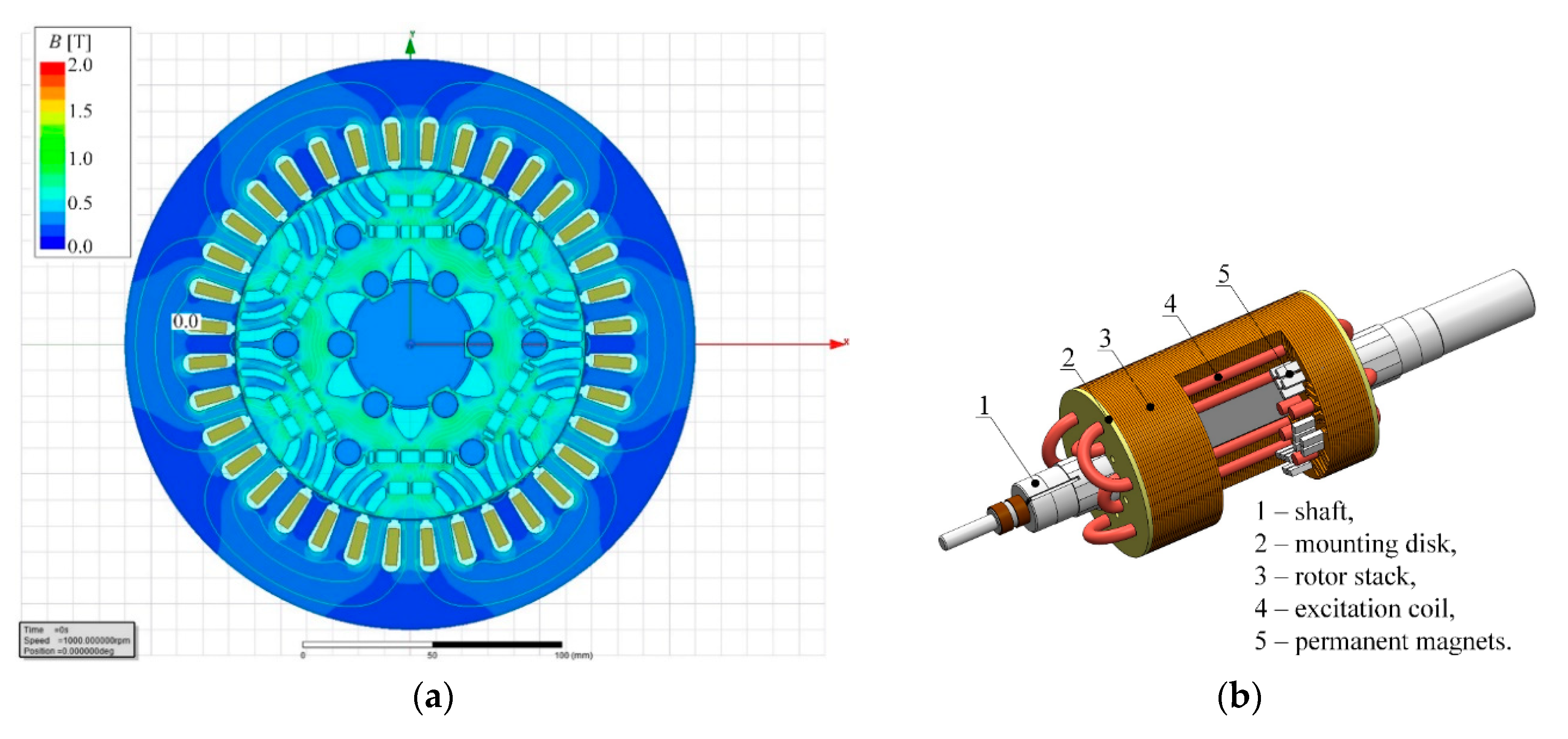
7. PM Electric Machine with Magnetic Barriers and Excitation Coils in the Rotor (HESMFB)
The purpose of the work of a new design of HESMFB machine was to develop a construction with magnetic flux barriers, embedded PMs and additional electromagnetic excitation in the machine rotor. It should be added that in order to achieve a wide speed control range of PM machines a large inductance ratio Lq/Ld (Lq—inductance in q-axis, Ld—inductance in d-axis) of the machine is required. The magnetic flux density distribution in the FEA model has been presented in Figure 21.
As can be seen in Figure 21a, the large saturation in magnetic bridges in the rotor close to the air gap and permanent magnets is noticeably. Due to this, flux leakage is reduced because the most of the magnetic flux passes through the air gap. Figure 21b presents a novel conception of the machine rotor with barriers and hybrid excitation.
During FEA investigations induced voltage waveforms have been plotted—Figure 22a, where α is a mechanical angle between rotor and stator. Furthermore the influence of additional windings current density (jDC) on the electromagnetic torque characteristics of the machine has been specified. These numerical tests have been conducted for three stator currents at Is max = 4; 8 and 12 A, at various additional winding current density jDC in the range from −8 A/mm2 to + 8 A/mm2 and for whole load angle range (from 0 to 360⁰el). The maximum values of electromanetic torque Te depending on jDC and Is max have been presented in Figure 22b.
Next, the experimental tests have been conducted. Figure 23 presents chosen experimental results and comparison with simulation predictions.
Figure 23 show that in the proposed machine the induced voltage control range from 77.6 V to 129.8 V has been obtained. Whereas according to FEA results the back-EMF control range from 72.2 V to 129.3 V was reached. It follows from the above that the field control range (FCR) for the experiment is 1.67 but for FEA-1.79. This means a good representation of the real machine using the developed simulation model. Regarding the cogging torque, the results of the experiment differ slightly from the results obtained in the simulations. However, these differences are rather minor. These differences may result from the not perfect torque measuring, because of very small its values and the FEA model’s mesh and accuracy.
8. Conclusions
The paper provides an overview of various hybrid excited machine topologies. In the literature a lot of solutions for hybrid excited machines can be found. In this paper the most common ones have been presented. Against this background, some new designs, sometimes completely innovative, developed by the authors were presented. In Table 3, the advantages, disadvantages and characteristic features of these machines are summarized.
Finally, we conclude that some of the presented solutions have very good flux control properties, but their complicated structure eliminates them from the possibility of practical application. Hence, the legitimacy of further search for such structures will be easy and inexpensive to manufacture, durable in operation, and at the same time will be characterized by a large range of control.
Author Contributions
All authors worked on this manuscript together. Conceptualization, M.W. and R.P.; investigation, resources, writing—original draft preparation and writing—review and editing, M.W., R.P., P.P. (Piotr Paplicki), P.P. (Pawel Prajzendanc), and T.Z. All authors have read and agreed to the published version of the manuscript.
Funding
This research received no external funding.
Acknowledgments
This work has been supported with the grant of the National Science Centre, Poland 2018/02/X/ST8/01112.
Conflicts of Interest
The authors declare no conflict of interest.
Nomenclature
| 2D | Two-dimensional |
| 3D | Three-dimensional |
| AFSPM machine | Axial flux switching permanent magnet machine |
| AT | Ampere-turns |
| CET | Contactless energy transfer |
| DC | Direct current |
| ECPMS machine | Electric controlled permanent magnet synchronous machine |
| EMF | Electromotive force |
| FC | Flux control |
| FCR | Field control ratio |
| FEA | Finite element analysis |
| FEM | Finite element method |
| FS | Flux strengthening |
| FSPM machine | Flux switching permanent magnet machine |
| FW | Flux weakening |
| HEAFM | Hybrid excited axial flux machine |
| HECPMLR | Hybrid excited claw pole machine with laminated rotor |
| HEFRM | Hybrid excited flux reversal machine |
| HEFS machine | Hybrid excitation flux switching machine |
| HEPM machine | Hybrid excited permanent magnet machine |
| HESMFB | Hybrid excited synchronous machine with flux barriers |
| IP | Iron pole |
| IPMSM | Internal permanent magnet synchronous machine |
| MMF | Magnetomotive force |
| N | North (pole) |
| NdFeB | Neodymium, iron, boron (type of permanent magnets) |
| PM | Permanent magnet |
| PMP | Permanent magnets pole |
| PM-SynRM machine | Permanent magnet assisted synchronous reluctance machine |
| RMS (rms) | Root mean square |
| RX | Receiver |
| S | South (pole) |
| SMC | Soft magnetic composites |
| SMPMAF machine | Surface mounted permanent magnet axial flux machine |
| SRM | Switched reluctance machine |
| TX | Transmitter |
References
- Zhu, Z.Q.; Cai, S. Overview of Hybrid Excited Machines for Electric Vehicles. In Proceedings of the Fourteenth International Conference on Ecological Vehicles and Renewable Energies (EVER), Monte-Carlo, Monaco, 8–10 May 2019. [Google Scholar] [CrossRef]
- Wang, Y.; Hao, W. General topology derivation methods and control strategies of field winding based flux adjustable pm machines for generator system in more electric aircraft. IEEE Trans. Transp. Electrif. 2020, 6, 1478–1496. [Google Scholar] [CrossRef]
- Zhu, Z.Q.; Cai, S. Hybrid excited permanent magnet machines for electric and hybrid electric vehicles. CES Trans. Electr. Mach. Syst. 2019, 3, 233–247. [Google Scholar] [CrossRef]
- May, H.; Palka, R.; Paplicki, P.; Szkolny, S.; Wardach, M. Comparative research of different structures of a permanent-magnet excited synchronous machine for electric vehicles. Electr. Rev. 2012, 88, 53–55. [Google Scholar]
- Wardach, M.; Paplicki, P.; Palka, R.; Cierzniewski, P. Influence of the rotor construction on parameters of the electrical machine with permanent magnets. Electr. Rev. 2011, 87, 131–134. [Google Scholar]
- Tesla Motor Designer Explains Model 3′s Transition to Permanent Magnet Motor. Available online: https://electrek.co/2018/02/27/tesla-model-3-motor-designer-permanent-magnet-motor/ (accessed on 27 October 2020).
- Di Barba, P.; Mognaschi, M.E.; Bonislawski, M.; Palka, R.; Paplicki, P.; Piotuch, R.; Wardach, M. Hybrid excited synchronous machine with flux control possibility. Int. J. Appl. Electromagn. Mech. 2016, 52, 1615–1622. [Google Scholar] [CrossRef] [Green Version]
- Trzmiel, G. Analysis of Power Control Methods in Wind Power Plants. Electr. Eng. Pozn. Univ. Technol. Acad. J. 2017, 89, 395–404. [Google Scholar] [CrossRef]
- May, H.; Shalaby, M.; Weh, H. Berechnung von geregelten permanent-magneten für tragen, führen und antriebsaufgaben. Etz Arch. 1979, 2, 63–67. [Google Scholar]
- Weh, H. Linear electromagnetic drives in traffic systems and industry. In Proceedings of the LDIA’95, Nagasaki, Japan, 31 May–2 June 1995. [Google Scholar]
- Weh, H.; May, H.; Hupe, H. Magnet concepts with one- and two-dimensional stable suspension characteristics. In Proceedings of the MAGLEV’89, Yokohama, Japan, 7–11 July 1989. [Google Scholar]
- Weh, H.; May, H.; Hupe, H.; Steingröver, A. Improvements to the attractive force levitation concept. In Proceedings of the MAGLEV’93, Argonne, IL, USA, 19–21 May 1993. [Google Scholar]
- Weh, H.; Steingröver, A.; Hupe, H. Design and simulation of a controlled permanent magnet. Int. J. Appl. Electromagn. Mater. 1992, 3, 199–203. [Google Scholar]
- Palka, R. Synthesis of magnetic fields by optimization of the shape of areas and source distributions. Arch. Elektrotechnik 1991, 75, 1–7. [Google Scholar] [CrossRef]
- Sikora, R.; Palka, R. Synthesis of Magnetic-Fields. IEEE Trans. Magn. 1982, 18, 385–390. [Google Scholar] [CrossRef]
- Schweitzer, G.; Traxler, A.; Bleuler, H. Magnetlager; Springer: Berlin/Heidelberg, Germany, 1993. [Google Scholar]
- Meins, J. Elektromechanik; Teubner: Stuttgart, Germany, 1997. [Google Scholar]
- Mbayed, R.; Vido, L.; Salloum, G.; Monmasson, E.; Gabsi, M. Effect of iron losses on the model and control of a hybrid excitation synchronous generator. In Proceedings of the IEEE International Electric Machines & Drives Conference, Niagara Falls, ON, Canada, 14–17 May 2011; pp. 971–976. [Google Scholar]
- Huang, M.; Huang, Q.; Zhang, Y.; Guo, X. A comprehensive optimization control method for hybrid excitation synchronous motor. Math. Probl. Eng. 2020. [Google Scholar] [CrossRef]
- Faleh, R.; Rahi, M.S. Improved performance of three phase motor with high power quality based on dual boost converter. Int. J. Innov. Res. Electr. Electron. Instrum. Control Eng. 2016, 4, 128–135. [Google Scholar] [CrossRef]
- Geng, H.; Zhang, X.; Zhang, Y.; Hu, W.; Lei, Y.; Xu, X.; Wang, A.; Wang, S.; Shi, L. Development of brushless claw pole electrical excitation and combined permanent magnet hybrid excitation generator for vehicles. Energies 2020, 13, 4723. [Google Scholar] [CrossRef]
- Luo, X.; Lipo, T.A. A synchronous/permanent magnet hybrid AC machine. IEEE Trans. Energy Convers. 2000, 15, 203–210. [Google Scholar]
- Xia, Y.; Yi, X.; Wen, Z.; Chen, Y.; Zhang, J. Direct Torque control of hybrid excitation permanent magnet synchronous motor. In Proceedings of the 22nd International Conference on Electrical Machines and Systems (ICEMS), Harbin, China, 11–14 August 2019. [Google Scholar]
- Fodorean, D.; Djerdir, A.; Viorel, I.A.; Miraoui, A. A double excited synchronous machine for direct drive application—Design and prototype tests. IEEE Trans. Energy Convers. 2007, 22, 656–665. [Google Scholar] [CrossRef]
- Hua, W.; Cheng, M.; Zhang, G. A novel hybrid excitation flux-switching motor for hybrid vehicles. IEEE Trans. Magn. 2009, 45, 4728–4731. [Google Scholar] [CrossRef]
- Sun, X.Y.; Zhu, Z.Q. Investigation of DC winding induced voltage in hybrid-excited switched-flux permanent magnet machine. IEEE Trans. Ind. Appl. 2020, 56, 3594–3603. [Google Scholar] [CrossRef]
- Chen, Z.; Zhou, N. Flux regulation ability of a hybrid excitation doubly salient machine. IET Electr. Power Appl. 2011, 5, 224–229. [Google Scholar] [CrossRef]
- Leonardi, F.; Matsuo, T.; Li, Y.; Lipo, T.A.; McCleer, P. Design considerations and test results for a doubly salient PM motor with flux control. In Proceedings of the IAS’96, Conference Record of the 1996 IEEE Industry Applications Conference Thirty-First IAS Annual Meeting, San Diego, CA, USA, 6–10 October 1996. [Google Scholar] [CrossRef]
- He, M.; Xu, W.; Zhu, J.; Ning, L.; Du, G.; Ye, C. A novel hybrid excited doubly salient machine with asymmetric stator poles. IEEE Trans. Ind. Appl. 2019, 55, 4723–4732. [Google Scholar] [CrossRef]
- Chen, Z.; Sun, Y.; Yan, Y. Static characteristics of a novel hybrid excitation doubly salient machine. In Proceedings of the Eighth International Conference on Electrical Machines and Systems, Tokyo, Japan, 27–29 September 2005; pp. 718–721. [Google Scholar]
- Ostroverkhov, N.; Chumack, V.; Monakhov, E. Synchronous axial-flux generator with hybrid excitation in stand alone mode. In Proceedings of the 2nd Ukraine Conference on Electrical and Computer Engineering, Lviv, Ukraine, 2–6 July 2019. [Google Scholar]
- Ostroverkhov, M.; Chumack, V.; Monakhov, E. Ouput voltage stabilization process simulation in generator with hybrid excitation at variable drive speed. In Proceedings of the 2nd Ukraine Conference on Electrical and Computer Engineering (UKRCON), Lviv, Ukraine, 2–6 July 2019. [Google Scholar] [CrossRef]
- Geng, W.; Zhang, Z.; Li, Q. Concept and electromagnetic design of a new axial flux hybrid excitation motor for in-wheel motor driven electric vehicle. In Proceedings of the 22nd International Conference on Electrical Machines and Systems (ICEMS), Harbin, China, 11–14 August 2019. [Google Scholar] [CrossRef]
- Hsu, J.S. Direct control of air-gap flux in permanent-magnet machines. IEEE Trans. Energy Convers. 2000, 15, 361–365. [Google Scholar] [CrossRef]
- Aydin, M.; Huang, S.; Lipo, T.A. A new axial flux surface mounted permanent magnet machine capable of field control. In Proceedings of the International Conference Record of the IEEE IAS Annual Meeting, Pittsburgh, PA, USA, 13–18 October 2002; pp. 1250–1257. [Google Scholar]
- Hoan, T.K.; Vido, L.; Gillon, F.; Gabsi, M. Structural optimization to maximize the flux control range of a double excitation synchronous machine. Math. Comput. Simul. 2019, 158, 235–247. [Google Scholar] [CrossRef]
- Mohammadi, A.S.; Pedro, J.; Trovão, F.; Antunes, C.H. Component-Level Optimization of Hybrid Excitation Synchronous Machines for a Specified Hybridization Ratio Using NSGA-II. IEEE Trans. Energy Convers. 2020, 35, 1596–1605. [Google Scholar] [CrossRef]
- Kosaka, T.; Matsui, N. Hybrid excitation machines with powdered iron core for electrical traction drive applications. In Proceedings of the ICEMS 2008 International Conference on Electrical Machines and Systems, Wuhan, China, 17–20 October 2008; pp. 2974–2979. [Google Scholar]
- Zhang, Z.; Liu, Y.; Zhao, W.; Wang, X.; Kwon, B. A novel dual-rotor permanent magnet synchronous reluctance machine with high electromagnetic performance. In Proceedings of the 22nd International Conference on Electrical Machines and Systems (ICEMS), Harbin, China, 11–14 August 2019. [Google Scholar]
- Naoeand, N.; Fukami, T. Trial production of a hybrid excitation type synchronous machine. In Proceedings of the IEMDC 2001 IEEE International Electric Machines and Drives Conference, Cambridge, MA, USA, 17–20 June 2001; pp. 545–547. [Google Scholar]
- Liu, Y.; Zhang, X.; Niu, S.; Chan, W.L.; Fu, W.N. Novel hybrid-excited permanent magnet machine based on the flux modulation effect. In Proceedings of the 22nd International Conference on Electrical Machines and Systems (ICEMS), Harbin, China, 11–14 August 2019. [Google Scholar] [CrossRef]
- Wei, L.; Nakamura, T. Optimization design of a dual-stator switched flux consequent pole permanent magnet machine with unequal length teeth. IEEE Trans. Magn. 2020, 56, 1–5. [Google Scholar] [CrossRef]
- Liu, X.; Lin, H.; Zhu, Z.Q.; Yang, C.; Fang, S.; Guo, J. A Novel dual-stator hybrid excited synchronous wind generator. IEEE Trans. Ind. Appl. 2009, 45, 947–953. [Google Scholar] [CrossRef] [Green Version]
- Liu, L.; Li, H.; Chen, Z.; Yu, T.; Liu, R.; Mao, J. Design of a hybrid excited permanent magnet machine with AC field winding excitation. In Proceedings of the 22nd International Conference on Electrical Machines and Systems (ICEMS), Harbin, China, 11–14 August 2019. [Google Scholar]
- Gao, Y.; Qu, R.; Li, D.; Li, J. A novel hybrid excitation flux reversal machine for electric vehicle propulsion. In Proceedings of the IEEE Vehicle Power and Propulsion Conference (VPPC), Hangzhou, China, 17–20 October 2016. [Google Scholar] [CrossRef]
- Diab, H.; Amara, Y.; Barakat, G. Open circuit performance of axial air gap flux switching permanent magnet synchronous machine for wind energy conversion: Modeling and experimental study. Energies 2020, 13, 912. [Google Scholar] [CrossRef] [Green Version]
- Noguchi, T. Proposal and operation characteristics of novel consequent pole permanent magnet motor. J. Phys. Conf. Ser. 2019, 1367, 012032. [Google Scholar] [CrossRef]
- Tapia, J.A.; Leonardi, F.; Lipo, T.A. Consequent pole permanent magnet machine with extended field weakening capability. IEEE Trans. Ind. Appl. 2003, 39, 1704–1709. [Google Scholar] [CrossRef] [Green Version]
- Upadhayay, P.; Kedous-Lebouc, A.; Garbuio, L.; Mipo, J.C.; Dubus, J.M. Design & comparison of a conventional and permanent magnet based claw pole machine for automotive application. In Proceedings of the 15-th International Conference on Electrical Machines, Drives and Power Systems (ELMA), Sofia, Bulgaria, 1–3 June 2017. [Google Scholar]
- Bruyere, A.; Henneron, T.; Locment, F.; Semail, E.; Bouscayrol, A.; Dubus, J.M.; Mipo, J.C. Identification of a 7-phase claw-pole starter-alternator for a micro-hybrid automotive application. In Proceedings of the 18th International Conference on Electrical Machines, Vilamoura, Portugal, 6–9 September 2008. [Google Scholar] [CrossRef] [Green Version]
- Popenda, A.; Chwalba, S. The synchronous generator based on a hybrid excitation with the extended range of voltage adjustment. Electr. Rev. 2019. [Google Scholar] [CrossRef]
- Paplicki, P. A novel rotor design for a hybrid excited synchronous machine. Arch. Electr. Eng. 2017, 66, 29–40. [Google Scholar] [CrossRef] [Green Version]
- Wardach, M.; Palka, R.; Paplicki, P.; Bonislawski, M. Novel hybrid excited machine with flux barriers in rotor structure. COMPEL 2018. [Google Scholar] [CrossRef]
- Wardach, M.; Bonislawski, M.; Palka, R.; Paplicki, P.; Prajzendanc, P. Hybrid excited synchronous machine with wireless supply control system. Energies 2019, 12, 3153. [Google Scholar] [CrossRef] [Green Version]
- Paplicki, P.; Prajzendanc, P. The influence of permanent magnet length and magnet type on flux-control of axial flux hybrid excited electrical machine. In Proceedings of the 14th Selected Issues of Electrical Engineering and Electronics (WZEE), Szczecin, Poland, 19–21 November 2018. [Google Scholar] [CrossRef]
- Wardach, M. Torque and back-emf in hybrid excited claw pole generator. COMPEL 2018. [Google Scholar] [CrossRef]
- Wardach, M. Hybrid excited claw pole generator with skewed and non-skewed permanent magnets. Open Phys. 2017, 15, 902–906. [Google Scholar] [CrossRef] [Green Version]
- Wardach, M. Design of hybrid excited claw pole machine with laminated rotor structure. In Proceedings of the Innovative Materials and Technologies in Electrical Engineering (i-MITEL 2018), Sulec̨in, Poland, 18–20 April 2018. [Google Scholar] [CrossRef]
- Wardach, M.; Paplicki, P.; Grochocki, P.; Piatkowska, H. Influence of rotor design on field regulation capability of hybrid excited electric machines. In Proceedings of the 14th Conference on Selected Issues of Electrical Engineering and Electronics (WZEE’2018), Szczecin, Poland, 19–21 November 2018. [Google Scholar] [CrossRef]
Figure 1.
(a) Levitation systems with controlled permanent magnets; (b) Unbalanced position with current compensation.
Figure 1.
(a) Levitation systems with controlled permanent magnets; (b) Unbalanced position with current compensation.

Figure 2.
(a) Conventional magnetic bearing; (b) Hybrid magnetic bearing.

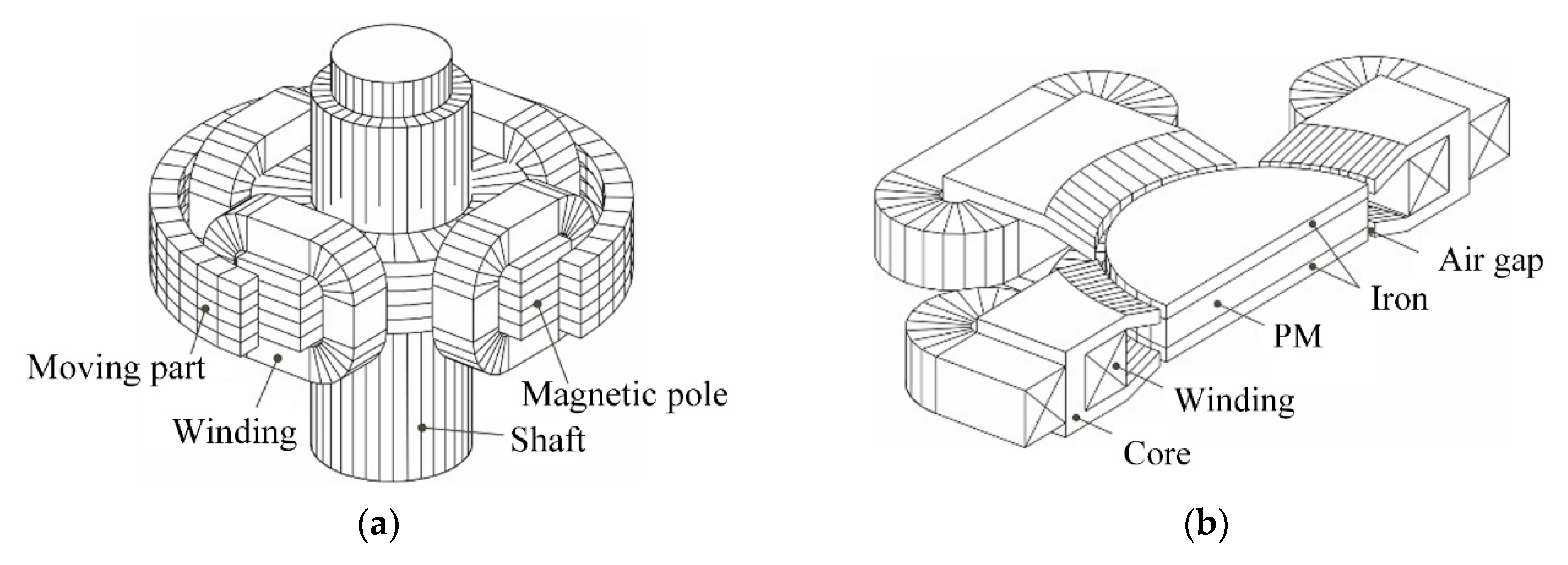
Figure 3.
ECPMS-machine design: (a) Design; (b) Prototype [54].
Figure 3.
ECPMS-machine design: (a) Design; (b) Prototype [54].

Figure 4.
(a) The stator DC control coil location in the prototype; (b) 3D-FEA model; (c) Results of no-load magnetic flux linkage Ψs vs. DC coil MMF of ECPMS-machine design [54].
Figure 4.
(a) The stator DC control coil location in the prototype; (b) 3D-FEA model; (c) Results of no-load magnetic flux linkage Ψs vs. DC coil MMF of ECPMS-machine design [54].

Figure 5.
(a) Experimental results of no-load speed obtained at constant DC-bus voltage of 100 V; (b) Back-EMF waveforms at 1000 rpm rotor speed; (c) Characteristics of no-load phase output voltage at the different DC coil MMF of ECPMS-machine [54].
Figure 5.
(a) Experimental results of no-load speed obtained at constant DC-bus voltage of 100 V; (b) Back-EMF waveforms at 1000 rpm rotor speed; (c) Characteristics of no-load phase output voltage at the different DC coil MMF of ECPMS-machine [54].

Figure 6.
(a) 3D-FE model with rotor DC control coil location; (b) Machine prototype with contactless energy transfer system; (c) Experimental results of no-load induced voltage in phase winding at the different DC coil MMF of ECPMS-machine [54].
Figure 6.
(a) 3D-FE model with rotor DC control coil location; (b) Machine prototype with contactless energy transfer system; (c) Experimental results of no-load induced voltage in phase winding at the different DC coil MMF of ECPMS-machine [54].

Figure 7.
HEAFM construction [55].
Figure 7.
HEAFM construction [55].

Figure 8.
Main principle of the HEAFM.

Figure 9.
The prototype of the HEAFM machine: (a) A stator with a rotor, (b) A complex machine with a caliper 20 cm long [55].
Figure 9.
The prototype of the HEAFM machine: (a) A stator with a rotor, (b) A complex machine with a caliper 20 cm long [55].

Figure 10.
Experimental stand [55].
Figure 10.
Experimental stand [55].

Figure 11.
RMS of induced experimental (dotted line) and simulation voltages (solid line) in no-load machine for IDC = −5 A (blue) and IDC = 5 A (orange).
Figure 11.
RMS of induced experimental (dotted line) and simulation voltages (solid line) in no-load machine for IDC = −5 A (blue) and IDC = 5 A (orange).

Figure 12.
Distribution of magnetic induction in a machine for the unpowered DC coil.

Figure 13.
The distribution of magnetic induction in air gap for different currents in the DC coil [55].
Figure 13.
The distribution of magnetic induction in air gap for different currents in the DC coil [55].

Figure 14.
Relation ΔFCR to the height of PM based on FEA [55].
Figure 14.
Relation ΔFCR to the height of PM based on FEA [55].

Figure 15.
Induced voltage waveforms depending on different DC coil currents for: (a) N38H and (b) F30 PM types [55].
Figure 15.
Induced voltage waveforms depending on different DC coil currents for: (a) N38H and (b) F30 PM types [55].

Figure 16.
Visualization of a claw pole machine: (a) With permanent magnets on one part of the rotor [56]; (b) With permanent magnets on both parts of the rotor [57].

Figure 17.
(a) Cogging torque waveforms for a machine with permanent magnets on one part of the rotor as a function of the current in the excitation coil (in kilo ampere-turns); (b) Maximum values of the cogging torque for a machine with permanent magnets on both parts of the rotor as a function of the angle γ, in a no-load excitation coil state [56,57].

Figure 18.
Test stand with HECPM [57].
Figure 18.
Test stand with HECPM [57].

Figure 19.
FEA model of HECPMLR [58].
Figure 19.
FEA model of HECPMLR [58].

Figure 20.
(a) Maximum value of the cogging torque depending on the current in the excitation coil; (b) Distribution of the back-EMF depending on the current in the excitation coil [58].
Figure 20.
(a) Maximum value of the cogging torque depending on the current in the excitation coil; (b) Distribution of the back-EMF depending on the current in the excitation coil [58].

Figure 21.
(a) Magnetic flux density distribution in the FEA model; (b) Concept of HESMFB machine rotor [59].
Figure 21.
(a) Magnetic flux density distribution in the FEA model; (b) Concept of HESMFB machine rotor [59].

Figure 22.
(a) No-load back-EMF waveforms at 1000 rpm under different current density levels; (b) Electromagnetic torque means values versus additional windings current density at the stator peak current Is max = 12 A [59].
Figure 22.
(a) No-load back-EMF waveforms at 1000 rpm under different current density levels; (b) Electromagnetic torque means values versus additional windings current density at the stator peak current Is max = 12 A [59].

Figure 23.
(a) RMS values of back-EMF; (b) Maximum values of cogging torque [59].
Figure 23.
(a) RMS values of back-EMF; (b) Maximum values of cogging torque [59].


Table 1.
Specification of tested PMs.
| Item (Unit) | Material Code | Remanent Magnetic Flux Density (T) | Coercive Force (kA/m) |
|---|---|---|---|
| Type A | N48H | 1.388 | 1058.8 |
| Type B | N38H | 1.248 | 947.8 |
| Type C | SmCo5 | 0.943 | 693.5 |
| Type D | F30 | 0.399 | 226.5 |
Table 2.
Air gap magnetic flux density distribution for different types of PMs.
| - | Type A | Type B | Type C | Type D |
|---|---|---|---|---|
| Magnetic flux near PMP ΦPMP | 2.05 mWb | 1.87 mWb | 1.63 mWb | 0.58 mWb |
| Magnetic flux near IP ΦIP | 0.76 mWb | 0.64 mWb | 0.48 mWb | 0.09 mWb |
| Percentage ratio of magnetic flux ΦIP/ΦPMP | 37.10 | 34.22 | 29.45 | 15.52 |
Table 3.
Characteristic features of tested machines.
| Machine Type | Advantages | Disadvantages | Features |
|---|---|---|---|
| ECPMS-machine | wide control range, FCR ~10, low PM demagnetization risk, possibility to locate DC coil on stator or rotor machine, or both | complicated structure, large dimensions | dedicated to high-speed drive, e.g., electromobility |
| HEAFM | middle control range useful FCR ~5 low PM demagnetization risk | very complicated structure, large dimensions | dedicated to low-speed applications, e.g., wind power |
| HECPM (HECPMLR) | middle control range, (easy implementation of complex rotor structures) | middle PM demagnetization risk, necessity to use brushes and slip rings or CET | dedicated to low and middle-speed applications, e.g., wind power |
| HESMFB | simple construction, middle control range, large inductance ratio Lq/Ld | middle PM demagnetization risk, necessity to use brushes and slip rings or CET | dedicated to high-speed drive, e.g., electromobility |
Publisher’s Note: MDPI stays neutral with regard to jurisdictional claims in published maps and institutional affiliations. |
© 2020 by the authors. Licensee MDPI, Basel, Switzerland. This article is an open access article distributed under the terms and conditions of the Creative Commons Attribution (CC BY) license (http://creativecommons.org/licenses/by/4.0/).
Share and Cite
MDPI and ACS Style
Wardach, M.; Palka, R.; Paplicki, P.; Prajzendanc, P.; Zarebski, T. Modern Hybrid Excited Electric Machines. Energies 2020, 13, 5910. https://doi.org/10.3390/en13225910
AMA Style
Wardach M, Palka R, Paplicki P, Prajzendanc P, Zarebski T. Modern Hybrid Excited Electric Machines. Energies. 2020; 13(22):5910. https://doi.org/10.3390/en13225910
Chicago/Turabian StyleWardach, Marcin, Ryszard Palka, Piotr Paplicki, Pawel Prajzendanc, and Tomasz Zarebski. 2020. "Modern Hybrid Excited Electric Machines" Energies 13, no. 22: 5910. https://doi.org/10.3390/en13225910
Note that from the first issue of 2016, this journal uses article numbers instead of page numbers. See further details here.