Virtual Oscillator Control of Equivalent Voltage-Sourced and Current-Controlled Power Converters †


Department of Electrical and Computer Engineering, United States Naval Academy, Annapolis, MD 21402, USA
*
Author to whom correspondence should be addressed.
†
This paper is an extended version of our work published in the IFAC Workshop on Control of Transmission and Distribution Smart Grids, Prague, Czech Republic, 11–13 October 2016.
Energies 2019, 12(2), 298; https://doi.org/10.3390/en12020298
Submission received: 27 November 2018
/
Revised: 4 January 2019
/
Accepted: 9 January 2019
/
Published: 18 January 2019
(This article belongs to the Special Issue Power Electronics in Renewable Energy Systems)
Abstract
:The dynamics of a general class of weakly nonlinear oscillators can be used to control power converters to create a self-forming AC network of distributed generators. Many control stability results for these “virtual” oscillators consider the interaction of voltage-source converters, but most practical converters use a nested current loop. This paper develops a general method to extend voltage-source stability results to current-controlled converters using a virtual admittance. A fast current control loop allows a singular perturbations analysis to demonstrate the equivalence of the two. This virtual admittance can also manipulate load sharing between converters without changing the core nonlinear dynamics. In addition, Virtual Oscillator Control is experimentally demonstrated with three-phase voltage-sourced and current-controlled inverters. This validates the equivalence of the two formulations, and extends previous single phase testing into three phases. The extension to current-controlled converters enhances safety and increases the breadth of applications for existing control methods.
1. Introduction
1.1. Motivation
The increasing penetration of power converters has raised new problems and opportunities in the control of small power systems and microgrids [1,2,3]. Power conversion decouples the physical dynamics of generators and loads from the rest of the system, allowing almost any set of dynamics to be substituted. Converter dynamics can be designed to facilitate load sharing, synchronization, and voltage and frequency regulation among multiple generators in both AC and DC power systems [4].
Historically, inverters would connect to an existing stiff AC power grid where a synchronous machine established the voltage and frequency. The proliferation of distributed generation and renewable energy has spurred interest in “grid forming” controls that can create a functioning AC power system using only power converters. However, the synchronous machines that comprise a standard power system have well-understood dynamics that serve to create an oscillating AC waveform and synchronize multiple power sources [5].
This innate feature of synchronous machines must be replaced by power converters. As a simple approach, the converters may have their own sinusoidal reference voltage generation, somewhat similar to the traditional Phase Lock Loop controls used with existing AC grids [6]. Alternatively, a synchronous machine’s dynamics can be simulated in software to produce a “Virtual synchronous machine” that uses tunable virtual parameters [7] to create the desired system dynamics including droop [8], frequency dynamics [9,10], and damping [11].
1.2. Approach
This paper focuses on an entirely separate method, a class of weakly nonlinear Liénard oscillators that form nearly sinusoidal stable limit cycles when simulated in software. They take the general form of a resonant linear oscillator with weakly nonlinear forcing terms, as [12,13]. Theoretical analysis has shown that coupled networks of these oscillators can produce the desired AC system behaviors including synchronization, stability, power sharing, and droop [14,15,16]. This general approach is termed virtual oscillator control (VOC) [12,13,17,18,19] because the oscillator dynamics are simulated to produce inverter commands. Two examples include the Van Der Pol Oscillator and the Nonlinear Dead Zone Oscillator (DZO) [17,18,19,20], which is the focus of the examples in this paper.
The theoretical analysis of VOC typically approximates a switching power converter as an ideal voltage source. Controller dynamics are assigned to command the output voltage as a function of output current. This is a logical approach for control of voltage-source converters. In practice, however, it is common to have a low-level current control loop to render the converter a controlled current source. A practical consideration critical to commercial utilization of power converters is the need to prevent damage to devices due to load anomalies. Semiconductors are sensitive to overloads of even short duration, and the current-controlled formulation makes it easy to enforce protective limits during faults, rapid transients, and low-voltage ride-through conditions. VOC based on the voltage-source formulation presents no obvious way to satisfy these protective limiting requirements, which presently restricts its commercial deployment.
This paper attempts to bring theoretical VOC converter control methods closer to deployment through three main contributions built on our previous work [20]. The first is a general theoretical approach that can extend a voltage-source analysis into a current-controlled version while maintaining its stability proofs, enabling more direct implementation into the current-controlled converters common in practice [20]. This method uses a simulated virtual admittance (the inverse of impedance) to create an equivalence between the two implementations under the assumption of fast current controller dynamics. A virtual admittance simulates the output current produced by a voltage difference across a component that exists only in simulation, while a virtual impedance simulates a voltage drop based on a current. The second contribution is the ability to control the power output and droop characteristics of current-controlled VOC inverters by varying their virtual output admittance, rather than the physical filter components as in the voltage-sourced derivation. Finally, we extend the experimental VOC results from the existing single-phase dead-zone oscillators [17,18,19] to three-phase voltage-sourced inverters, and then to three-phase current-controlled inverters using the equivalence technique. Compared to our previous work [20], this paper adds a more detailed theoretical analysis, simulations, voltage-sourced inverter testing, and considers current controllers with limited bandwidth.
1.3. Literature Review
The idea of virtual admittance is not new in converter controls [21,22,23,24,25,26]. It has been studied for DC systems to create droop phenomena and enforce power sharing in DC [23,27,28] and AC [24,29,30,31] microgrids, and similarly in battery management systems [22]. Another application is to regulate harmonic voltages in current-controlled inverters [29,32]. The idea of having dual voltage-sourced or current-controlled implementations has been studied for virtual synchronous machines, where the simulated dynamics already include a clear method to implement the two variants [33,34]. The novelty here and in our previous work is using virtual admittance to enable current control for VOC controllers, which have no obvious method to create a current-controlled equivalent.
When operating as a voltage-sourced virtual oscillator, tuning the effective output impedance of an inverter requires changing the core oscillator dynamics or the inverter’s physical output filter. However, the effective output impedance of a current-controlled inverter can be manipulated by changing only a virtual admittance [20]. As a consequence, the relative power contributions of parallel-connected current-controlled inverters can be manipulated without changing the core oscillator control or any physical components. The idea of varying virtual impedances or admittances to enforce a desired power sharing arrangement in voltage controlled inverters was shown in [30,35], but is new for VOC applications.
To demonstrate these ideas, we implemented them experimentally using the dead zone oscillator for virtual oscillator control. A key feature of DZO control is that the parameters can be tuned such that parallel-connected inverters self-synchronize with no communication other than that inherent to their common electrical coupling [18]. Existing DZO work assumes voltage-source inverters and was tested in single-phase [17,18,19]. This paper extends the hardware testing to three-phase via the Clarke transformation [19]. The voltage-to-current conversion is then used to drive three-phase current-controlled inverters, as in our previous work [20]. The resulting AC grid in both cases demonstrates self-synchronization, voltage and frequency regulation, controllable load sharing, and droop characteristics, all without dedicated communication between units. The testbed parameters for both current and voltage-controlled systems were identical thus proving the stability characteristics apply under either control framework.
The proposed DZO control method is only one of many available for microgrid control. Most involve some form of low level control, combined with a hierarchical control scheme. Droop control is commonly used for the low level, in which the voltage and/or frequency reference are modified based on the measured real and reactive power outflows [6,36,37]. DZO control does not explicitly implement this phenomenon, but the nonlinear dynamics of the system inherently exhibit this same behavior [12,13]. There are many proposed algorithms for hierarchical control between multiple converters [38,39], but DZO functions in a truly distributed fashion without a higher level controller.
This paper is organized as follows: Section 2 describes the extension of voltage-source stability results to the current-controlled case. Section 3 summarizes DZO dynamics for both voltage and current-controlled variants, and Section 4.1 describes the testbed setup. Section 4.2 describes simulation results, while Section 4.3 presents the results of hardware testing which demonstrate three phase DZO synchronization, load sharing, and response to step changes in loads.
2. Voltage- and Current-Controlled Inverters
This section describes a typical model of a voltage-sourced converter and its interaction with a grid or load. It then describes how the same dynamics and control can be used with a current-controlled inverter. This concept initially appeared in [20].
2.1. Converter Models
A simple voltage-source converter with ideal semiconductor switches is illustrated in Figure 1. The current and voltage are measured at the output of the inverter bridge. An inductor and a parallel capacitor serve as an output filter, however, these elements may be eliminated if filtering is not required. The voltage where the output of the converter connects to the grid is labeled . The converter establishes a voltage given the injected current and activity in the rest of the system. The “Grid” component G represents everything external in the system: loads, impedances, and other inverters. Although Figure 1 depicts a single-phase AC converter, different switch configurations can produce three-phase or DC converters.
Assuming the switching dynamics are sufficiently fast to be neglected and by replacing the inverter bridge with an ideal voltage source, the voltage-source converter can be further simplified into Figure 2. The series-connected inductor filter has been replaced in the system by which uses the voltage drop to calculate a current. Also, the parallel-connected capacitor filter is combined with the grid system, now denoted .
2.2. Voltage-Sourced Analysis
For an AC or DC converter system, stability analysis depends on assumptions about the following elements: The dynamics of the controller; the grid impedance seen at the output of the voltage source; and the switching dynamics, which are fast and often neglected.
The software-based oscillator controller C has an internal state that evolves with dynamics and assigns a voltage based on the output function in response to , the measured output current. This current is produced by the voltage drop across the output filter F via its internal dynamics and output function . In a similar manner, the internal model of the grid is specified by with output . It should be noted that the components C, F, and may all be nonlinear. The basic equations are thus
In the case where the F is linear, it becomes an admittance.
2.3. Current-Controlled Equivalent
To adapt the previous analysis for the case of a current-controlled converter, we assume a sufficiently fast current-control loop (PI or similar) which allows the converter to maintain a desired output current by varying the converter output voltage. Because the current controller must be able to modulate output current, it will not function with an open circuit. Hence, we require the output impedance to be bounded. To meet this condition even if the grid interface to the converter terminals G is unconnected, we include a parallel-connected filter capacitor as in Figure 1.
Under this ideal current-controlled model, the effects of the series filter on current are removed as it is within the closed-loop portion. Yet, this offers the possibility to simulate the effect of any desired output filter in software as a virtual impedance as shown in Figure 3.
To create this system, start with the simulated controller output and subtract the measured terminal voltage to create the voltage difference needed to calculate output current with . This current is then fed back as the current command . The dynamics of the current controller K are added as (10) to drive the actual current to the desired and yield the modified system
The “singular perturbations” theorem [40] states that for a dynamical system where a portion of the dynamics are much faster than the rest, those fast dynamics can be treated as an algebraic relationship. Assuming the current controller K is fast compared to the other dynamics and drives the current tracking error to zero, in (10) approaches zero. A singular perturbations argument [40] allows us to consider (10) as an algebraic relationship, and the converter can be treated as a current source where matches exactly the desired within the bandwidth of the current controller. This reduces the current controlled system (7)–(13) to match the original voltage source system (1)–(6) with the original filter dynamics F replaced with the virtual filter .
For a voltage-source model, the output impedance includes the series output filter of the inverter in Figure 2, which is a physical hardware component. For the current-controlled version, the physical output filter impedance is neglected due to the ideal current control loop, but a simulated filter impedance is included in the controller dynamics. This makes the full system analysis and system dynamics identical to the previous case, except for that filter dynamics are now virtual rather than real.
Thus, for , the system dynamics are identical to the voltage-source case. This method makes no assumptions about linearity or AC vs. DC operation. The main underlying assumption is that the current loop is stable and much faster than other dynamics such that converges to . A necessary condition for this assumption is the effective grid impedance must be finite.
Specifying the inverter’s effective output filter as a virtual impedance whose characteristics are controlled via software offers several benefits. Firstly, methods exist to control power sharing, droop, etc. based on this filter, thus software control of this parameter permits unlimited flexibility as compared to changing the actual hardware values. Also, most causal filter models can be implemented independent of the actual hardware. This also permits improved analysis since the simulated filter impedance will be accurately known. This is not always the case with actual hardware.
Although presented here for the single-phase AC case, this current-controlled model similarly extends to three-phase systems for both unbalanced or nonlinear conditions.
2.4. Non-Ideal Current Amplifiers
This equivalent controller method relies on a current control loop or current source that rapidly tracks the commanded current (10). Typically, this is only true within a specific frequency range, and so long as the current controller is sufficiently fast compared to the oscillator dynamics, the singular perturbations analysis holds. For completeness, consider the behavior of the system as the base dynamics approach the bandwidth of the current controller, and the tracking performance weakens.
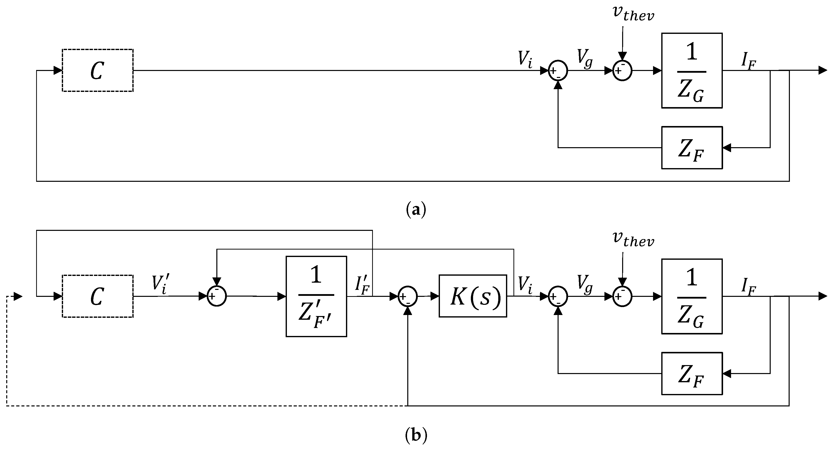
Consider the transfer function at the output of the controller C, which sends a commanded inverter voltage, and receives a current feedback. The voltage-source converter of Figure 4a observes an output transfer function that behaves as a simple impedance
The more complex current-controlled converter of Figure 4b observes the output transfer function
When the current controller gain is large, those terms dominate, and the transfer function reverts to the form of the voltage-sourced version (14), with the virtual filter replacing the hardware filter , as expected. If becomes very small, for example if the output is disabled, the dynamics reduce to the simple impedance of the virtual filter .
As an alternative, the feedback current could be the output of the real system, rather than the commanded current, as shown by the dashed feedback line in Figure 4b. In this case, the transfer function seen by the oscillator control output is
This configuration exhibits the same behavior when current controller gain is large, again matching the form of the voltage-sourced version (14), with the virtual filter replacing the hardware filter. However, as the gain approaches zero, this output transfer function also approaches zero to reflect the reality that there is little real output current. This alternative method is not used in the results presented in this paper, but its behavior may be desirable in specific applications.
2.5. Synchronization and Over-Current Protection
Converters typically have output filters with impedances of 5%–20% per unit at the fundamental frequency. Directly connecting a voltage-source virtual oscillator via switch or a bridge and enabling switching without synchronizing first will usually result in a large current spike that will either damage the converter or trip the protection. This is not an issue from an analysis or stability perspective, but can cause significant damage in hardware.
Current-controlled inverters can be set to self-limit this current spike, protect the device, and continue operating. This is one reason why current control loops are used so often in practice.
Voltage-controlled inverters cannot directly limit current in the same way, and they are often protected by software trip logic that instantly ceases outputs if the measured current exceeds given threshold values. In normal operation this is not a problem, but a direct startup to an operating grid will trip the protection.
For the voltage-controlled case, one possible solution is to achieve some degree of synchronization before connecting the converter or enabling the switching action. This can be achieved with a voltage measurement on the line side of any switches or breakers. One approach is to use this voltage measurement to adjust the states of the oscillator to match the grid oscillation.
A second approach is used in the experimental section of this paper. The line-side voltage measurement is fed to the control software, and a simulated output admittance is connected between the oscillator dynamics and the grid. This process is entirely virtual and results in no real currents or voltages, but it does synchronize the oscillator dynamics in software before the physical converter is connected or enabled.
3. Application of Dead-Zone Oscillator Control to Current and Voltage-Controlled Three-Phase Inverters
DZO control was formulated in [17,18,19] as a voltage-source algorithm, but a current-controlled equivalent would both increase the breadth of application for DZO control and offer the advantages of controlling the effective output impedance of inverters through software. To these ends, the method developed in Section 2 of adapting voltage-source control algorithms to current-controlled converters is applied to DZO control. The basics of this method are summarized here for convenience. The various stability and convergence proofs are found in [17,18,19].
3.1. Dead-Zone Oscillator Control
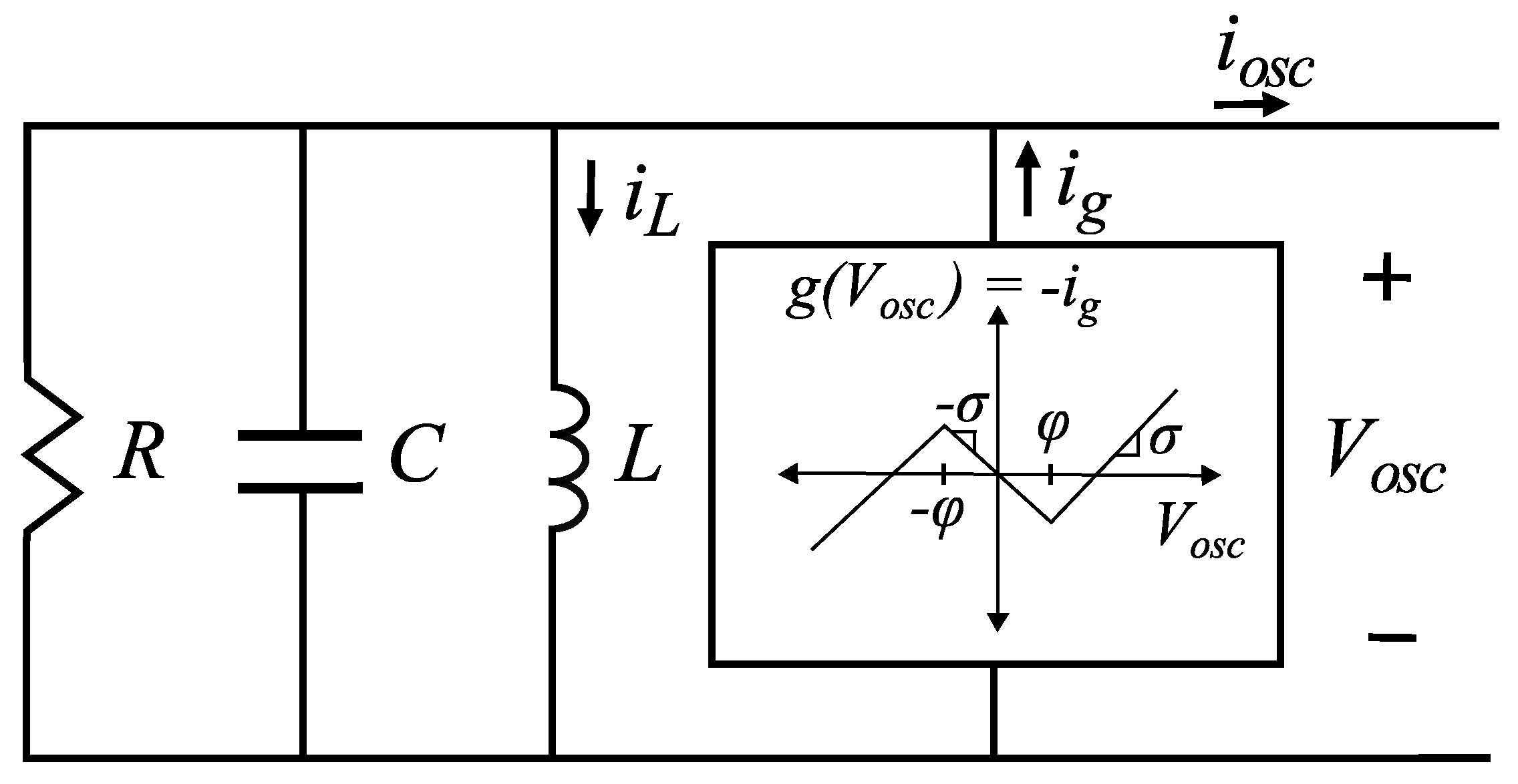
Under DZO control, an inverter mimics the dynamics of a nonlinear DZO in a manner similar to the well-known Van der Pol oscillator. A DZO circuit equivalent model, shown in Figure 5, consists of a nonlinear voltage-dependent current source and a parallel resistor inductor capacitor (RLC) circuit.
The DZO [17,18,20] is a nonlinear dynamic system of two states: The DZO terminal voltage and the inductor current with dynamics specified by
where is the dead-zone function with parameters and , and is the voltage-current characteristic of the voltage-dependent current source, which is related to by (19).
The dynamics of the DZO, as presented in [18], are governed by the parameters of and by the impedance of the parallel RLC circuit. For a standalone inverter, has a stable, unique limit cycle if . If , it can be shown that the limit cycle is approximately sinusoidal with frequency close to the natural frequency of the RLC circuit, .
When multiple inverters under DZO control are connected in parallel, each inverter’s output current is determined by , , and , and because each inverter’s output current depends on the common grid voltage, the inverters demonstrate the ability to self-synchronize. Further, due to the dependence of the inverter current on its own output filter impedance , load-sharing between inverters can be controlled by changing .
3.1.1. Voltage-Controlled Inverter DZO Requirements
The DZO control derivation and testing was initially created for use in voltage-source inverters. The controller measures the current at the terminal of the inverter and commands the bridge voltage .
3.1.2. Adaptation of DZO Control to Current-Controlled Inverters
DZO control can be extended from voltage-source inverters to current-controlled inverters using the approach presented in Section 2. As illustrated in Figure 3, the DZO terminal voltage and the voltage measured at the grid terminal are used to compute , which are both sent as a control signal to the current-controlled inverter and fed back into the DZO model to calculate the value of at the next time step.
3.2. Extension of DZO to Three-Phase Networks
In [19], the Clarke Transform was used to generate the balanced three-phase voltage control signal from and , the virtual inductor current of (18). For control of current-controlled inverters in the test bed described here, is generated in the same way.
3.3. Software DZO Inverter Synchronization
Voltage measurements are processed by the controller to provide a reference for multiple inverter synchronization. During initial startup of additional inverters when at least one is already running, software in the starting inverter synchronizes the output of the inverter with AC voltage across the load to decrease potential current spikes upon connecting multiple inverters across the same load. Before the inverter switches are enabled, the load side voltage measurement is fed to the simulated oscillator and connected through a virtual impedance. This triggers the natural synchronization behavior of the oscillator and causes it to synchronize with the grid before the output bridge is enabled, minimizing transients.
4. Results
4.1. Test Bed Configuration
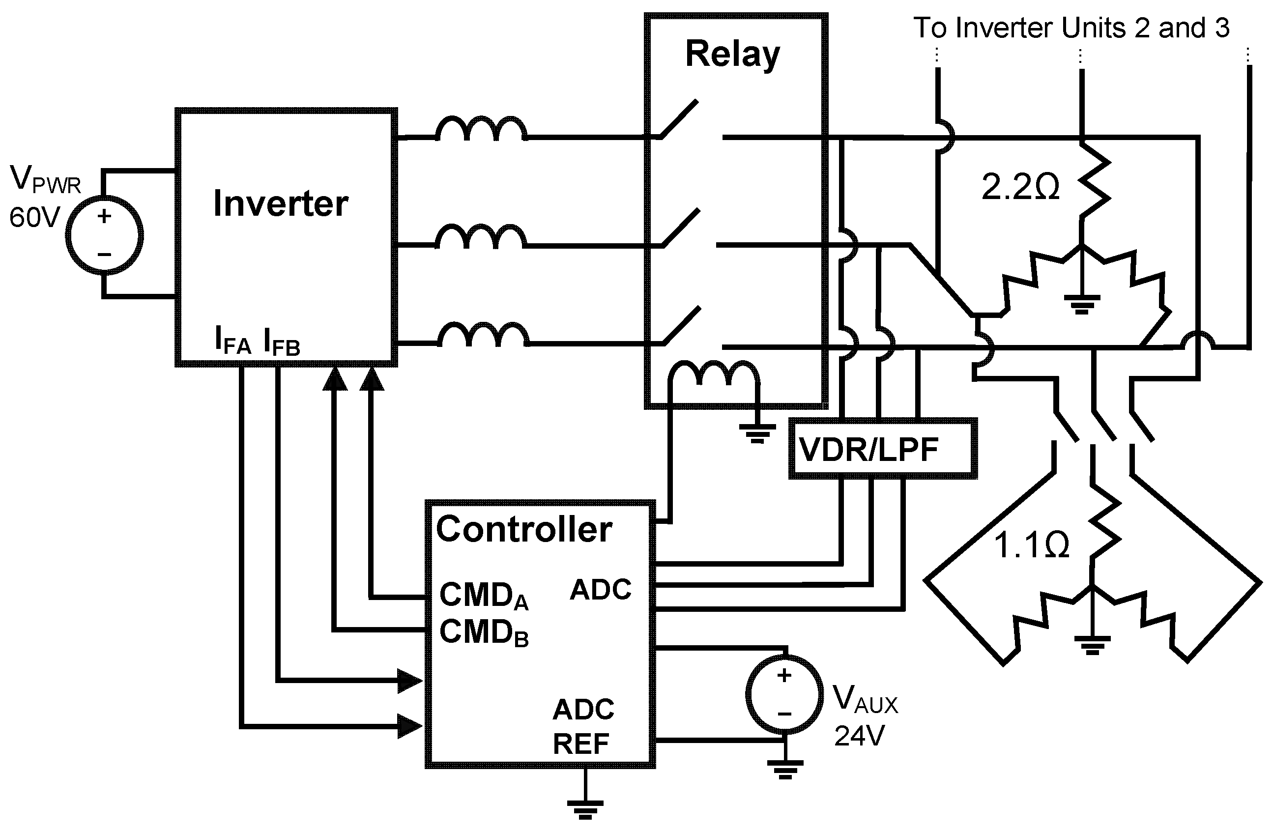
The three-phase testbed consists of three inverter subunits connected in parallel to a Y-connected resistive load. The general configuration is identical for both current- and voltage-controlled inverters. Figure 6 shows one inverter subunit connected to the load, and displays the core functional elements of the subunit. A picture of this unit in the physical testbed is shown in Figure 7 without the attached load.
The controller samples and , the grid voltages on the A and B phases, each at a rate of 10 kHz. Current measurements from the inverter are also fed back into the controller for processing. An analog signal conditioning board provides a voltage divider and low-pass filter with a single pole at 22 kHz.
The controller sends a reference command to the inverter, either an A- and B-phase voltage or an A- and B-phase current depending if the inverter is voltage-sourced or current-controlled.
Current and voltage measurements are fed back to the controller regardless of the controller type. The voltage-controlled variant nominally requires only current feedback, while the current-controlled variant requires only voltage feedback. However, both types use the voltage measurement for initial grid synchronization, and current measurements for over-current protection.
Each inverter subunit’s controller actuates a normally-open relay to connect the subunit to the grid. For a current-controlled inverter, an open circuit can create control loop stability problems, so when the relay is open the controller holds the states of the simulated oscillator and the current commands at zero to prevent current loop saturation. The governing state equations of the dead-zone oscillator are discretized and solved in real time with a fixed step size of 100 s.
4.2. Simulation Results
The dead zone oscillator system with both voltage-sourced and current-controlled amplifiers was simulated in the MATLAB/SIMULINK environment. The ability of the current amplifier to accurately track current commands is critical to the correct functionality of the system, as described in Section 2.4. The simulation was configured and tuned to match the test bed, with both voltage-sourced and current-controlled amplifiers connected through a 150 H inductor to a Y-connected resistor bank. The current controller is a Proportional Integral (PI) type.
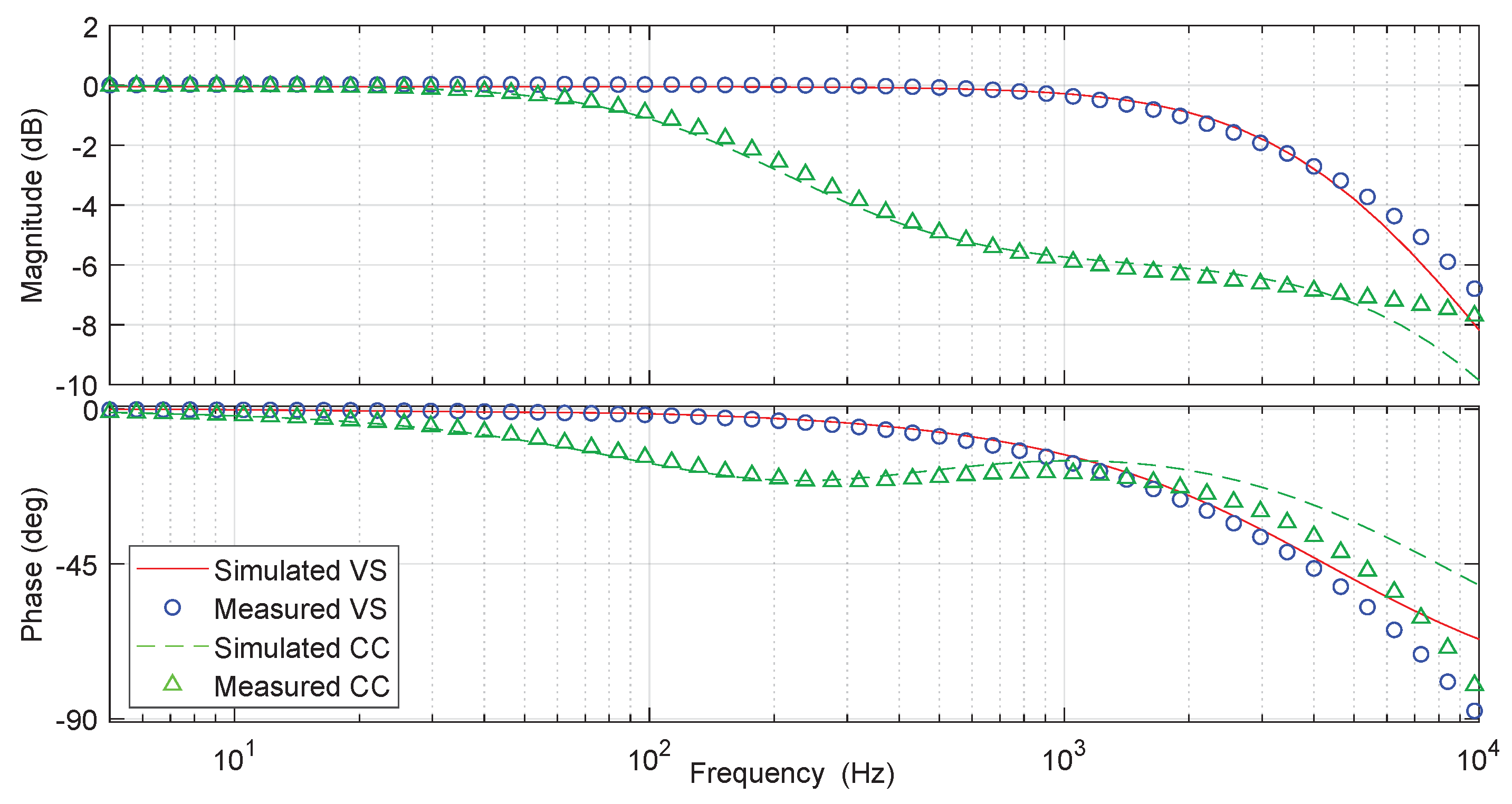
To understand the amplifier response, the transfer function from amplifier command to output current was measured via a frequency sweep in the amplifier reference input as shown in Figure 8.
For the voltage-sourced inverter, the voltage command was scaled by the output resistance () so that a 1 V command would nominally produce 1 A and measure 0 dB. This is visible in both the simulated and measured output currents until at least 1 kHz, when the current response rolls off due to the system L/R pole at 4.2 kHz. This means the voltage follows the command very well within this measurement window.
The current-controlled amplifier response is shown as the transfer function from current command to current output. In this case, both real and simulated current controllers show good tracking until a dB bandwidth of about 200 Hz, when the response no longer tracks the command. So for this system, both simulation and hardware tests indicated that the current-controlled and voltage-sourced systems should be equivalent for frequencies below about 100 Hz. This should suffice for the steady-state behavior of oscillators set for 60 Hz. Rapid transients may cause the two versions to diverge somewhat.
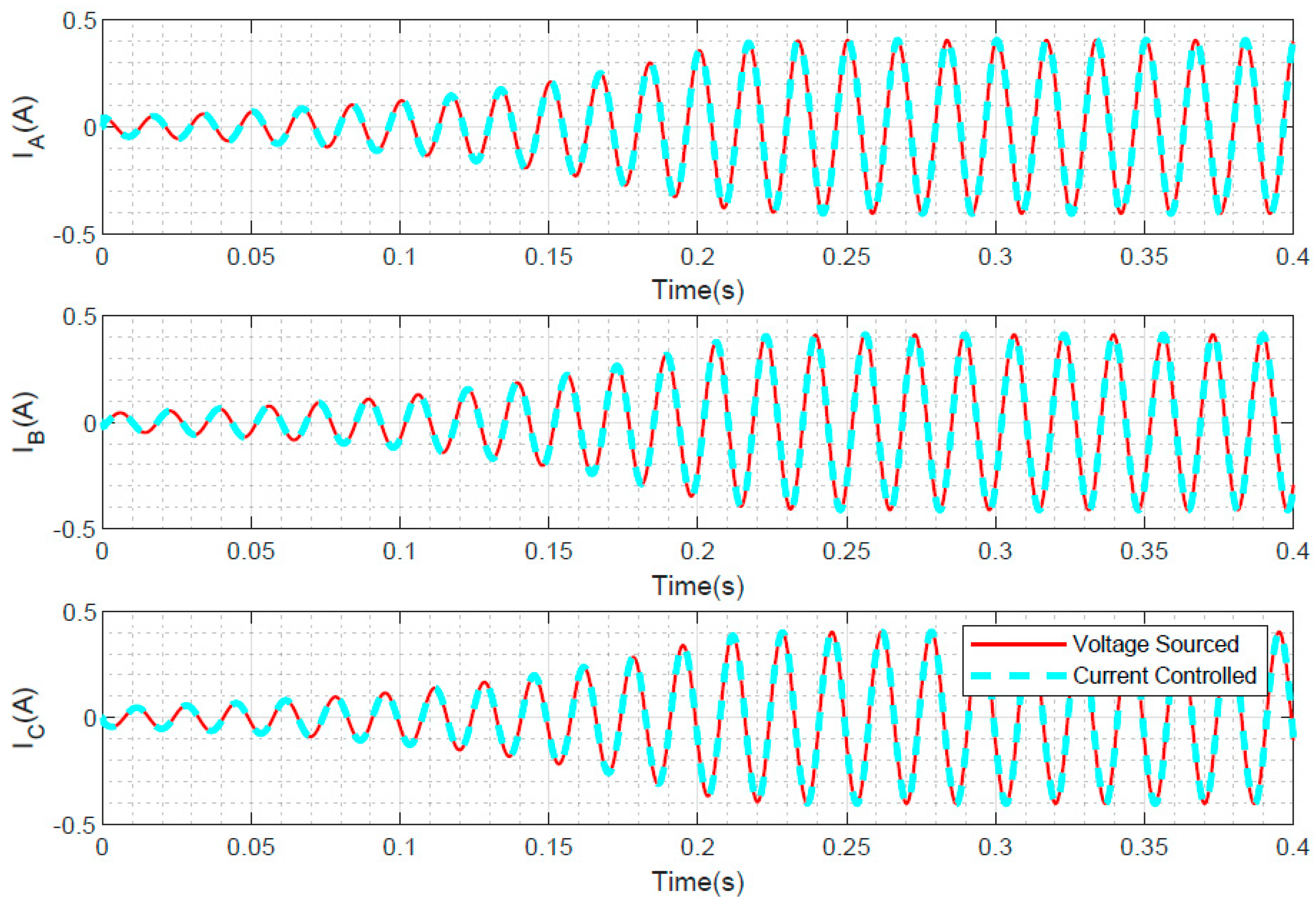
The basic operation of the virtual oscillator is tested in simulation by starting from a zero initial condition. The system starts from rest, begins oscillating with increasing amplitude, and reaches a stable limit cycle. Both voltage-sourced and current-controlled versions are shown in Figure 9, and demonstrate good agreement between the two.
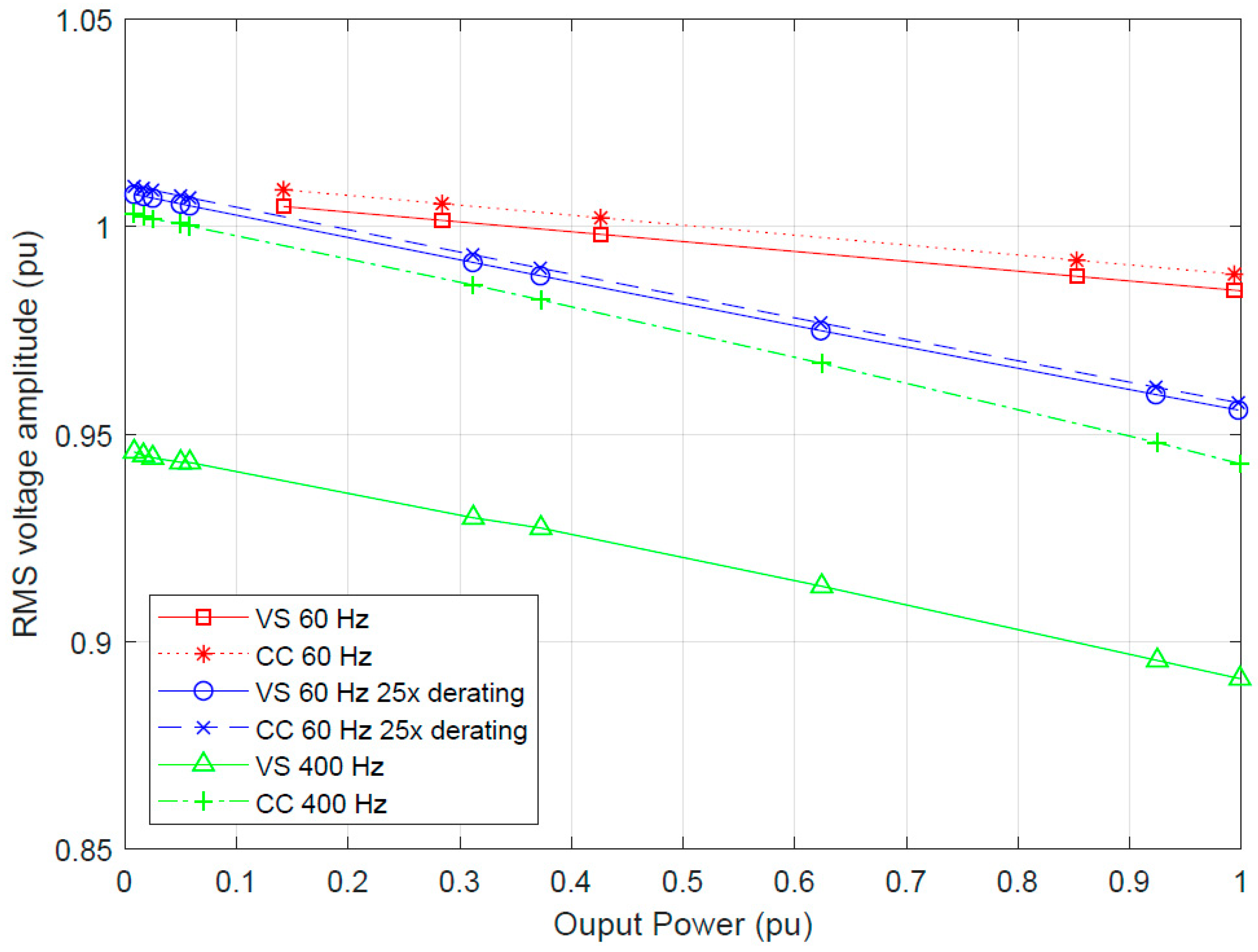
To study the effects of the two different implementations in a more realistic scenario, simulations were conducted to study the droop characteristics of the oscillator. As more power is drawn from the system, the output voltage decreases based on the nonlinear oscillator dynamics. This feature aids in load sharing between inverters. As shown in Figure 10, the voltage-sourced and current-controlled versions match very well during 60 Hz operation for two different nominal power ratings of the oscillator. However, when set for 400 Hz operation, more divergence appears. This validates the predictions of the current tracking response shown in Figure 8, which starts to introduce errors above about 100 Hz.
4.3. Experimental Results
This section experimentally demonstrates three phenomena that are useful for practical implementation of oscillator-based converter controls. The first is the three-phase voltage-source DZO control theoretically developed and simulated (but not tested) in [19], including synchronization and the predicted power droop characteristic. The second is the equivalent performance of a current-controlled inverter to its voltage-controlled counterpart, including oscillation and synchronization of parallel-connected inverters regardless of their control framework. This validates the results of Section 2.
The final tests demonstrate the ability to dynamically change and control the power output of a current-controlled inverter by adjusting a virtual output filter admittance as described in Section 2.3. The ability to alter the load-share of an inverter by changing its physical output filter was demonstrated for single-phase voltage-controlled inverters in [17]. Changing a virtual output filter as described here achieves the same result, and can be done dynamically without hardware changes. This concept is only applicable to the current-controlled implementation.
4.3.1. Voltage-Controlled Inverter
A three-phase voltage-sourced converter using DZO control was tested for self-oscillation, step changes in load, synchronization, and droop characteristics. The behavior matches expectations, confirming the theoretical results in [19].
As a first test, a single inverter self-oscillates and powers a Y-connected load of per phase as shown in Figure 11a. The load resistance then changes to (66% decrease) in each phase. A brief transient occurs, then settles to a steady state at higher current values as expected.
An important feature of DZO control is synchronization with other inverters. In Figure 11b, one inverter is operating and powering a load, and another inverter is then connected. They synchronize and then share the current provided to the load.
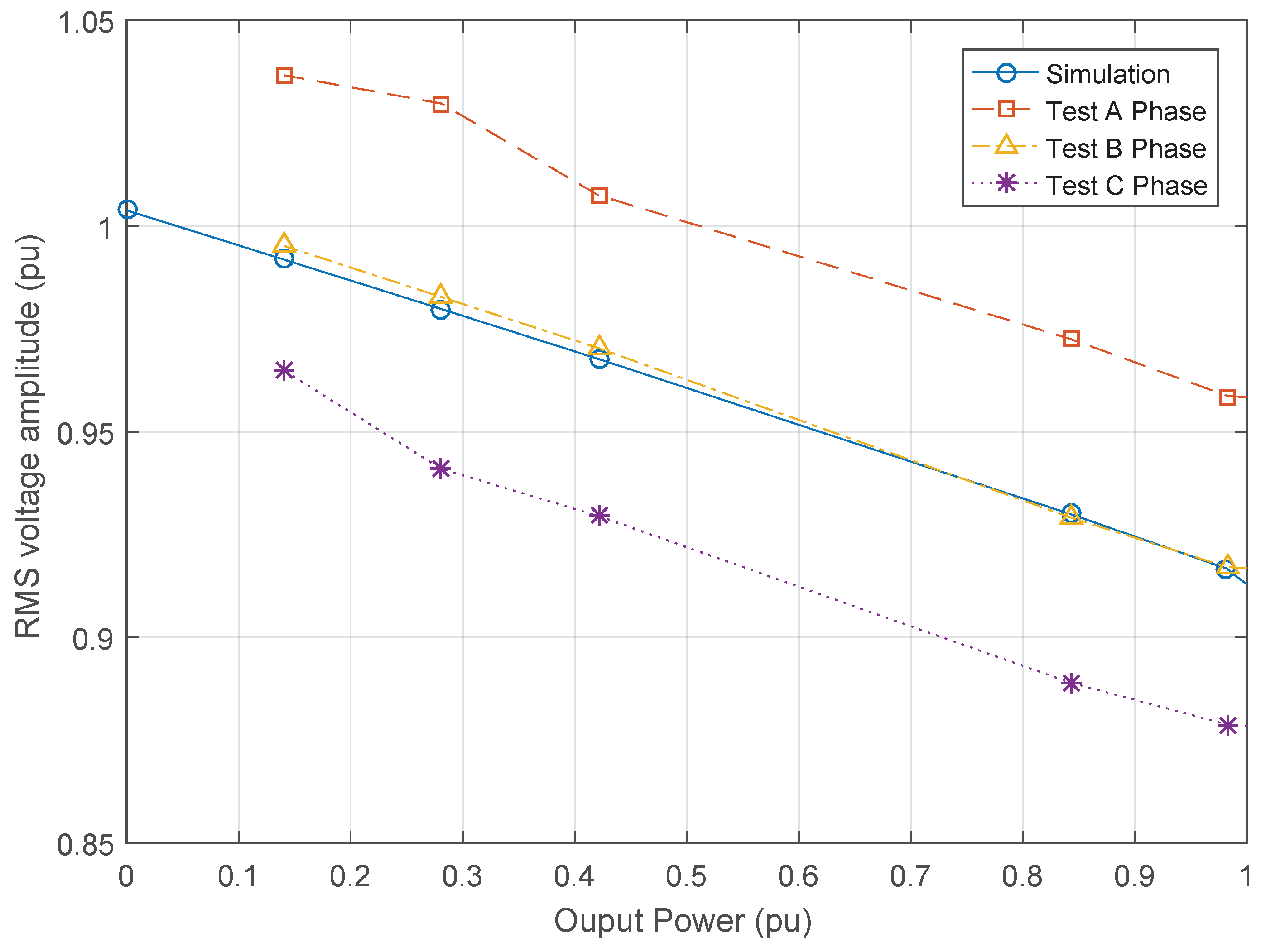
Finally, the DZO dynamics yield a droop characteristic where the output voltage drops in the presence of increasing load. The predicted and experimental results are shown in Figure 12. The simulation results are perfectly symmetric and all three phases yield the same voltage, current, and power magnitudes. The experimental results indicate some discrepancy between phases, but the general trend is the same. The output power is calculated based on the load resistance and the nominal output voltage.
4.3.2. Current-Controlled Inverter
Three-phase current-controlled converters were tested for self-oscillation, synchronization, and step changes in load. These are the same physical converters as in the voltage-controlled case, but they have an internal current feedback loop such that the command from the microprocessor to the converter is a current command.
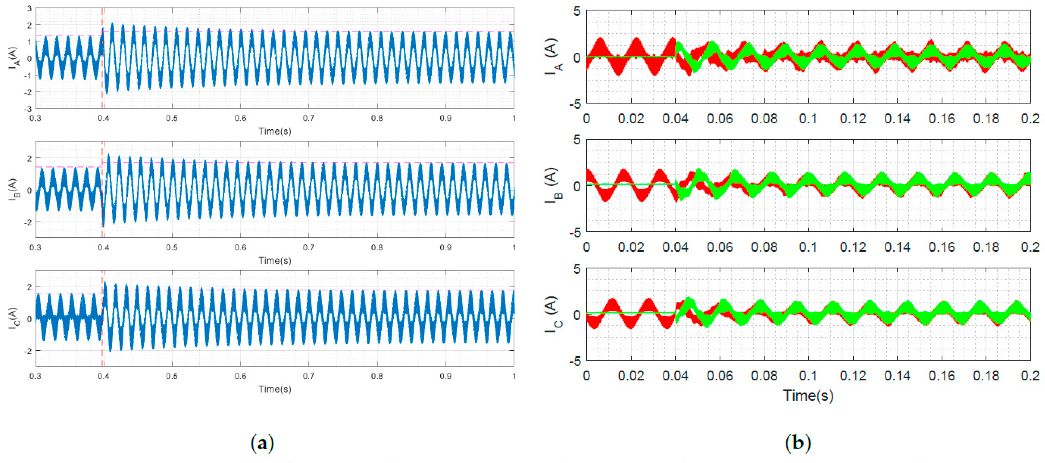
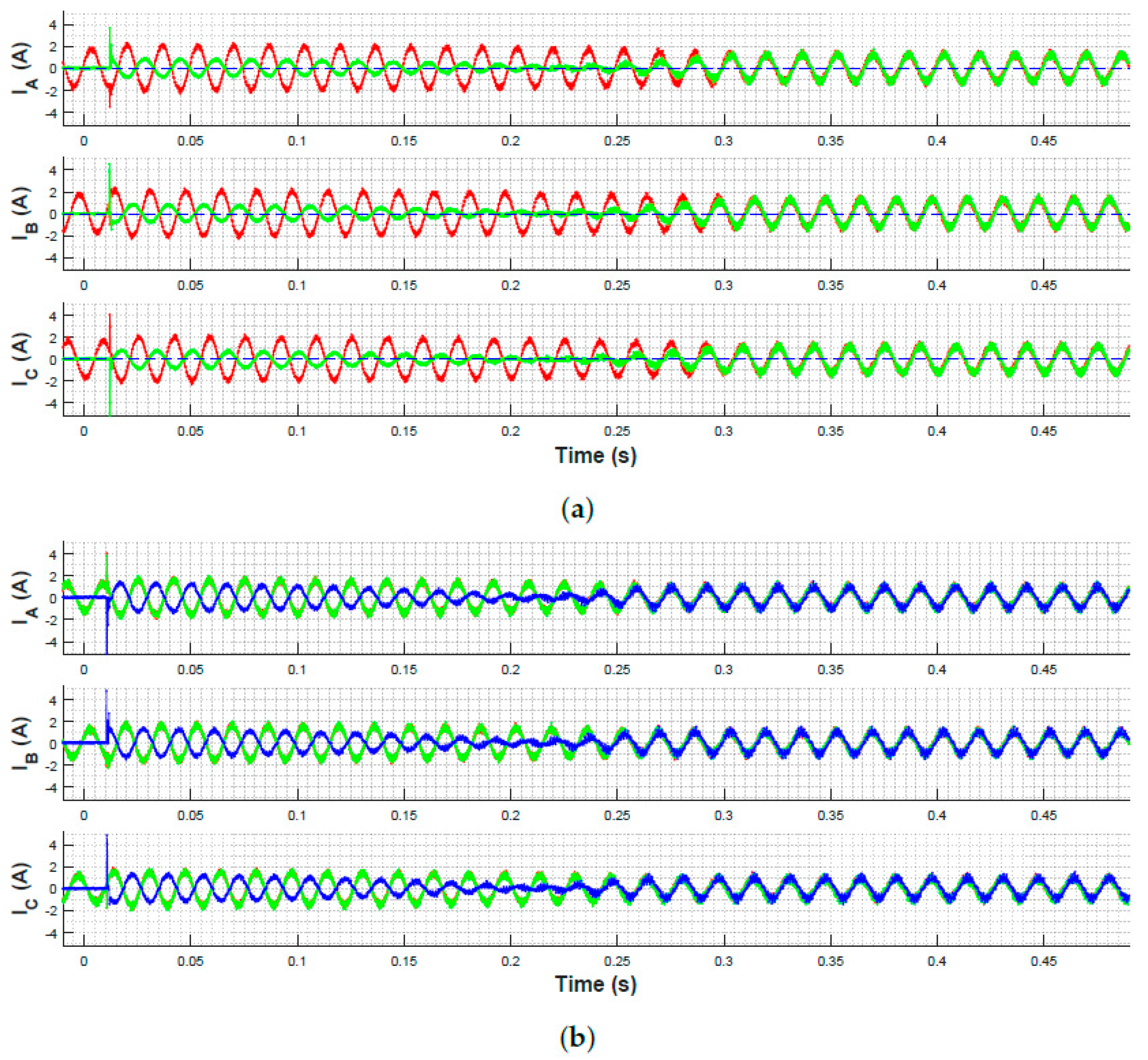
In the first test case, a single inverter self-oscillates to power a load, and a second inverter is then connected. The three phase current measurements from each inverter are shown in Figure 13a. They synchronize and begin to share load. A current spike occurs 10 ms after the synchronizing inverter is connected, reaching a maximum of 4.64 A on one phase. Out-of-phase oscillation is observed from 10–200 ms after connection, and then low-amplitude oscillation of the synchronizing inverter from 200–250 ms. Both converge to full-amplitude, in-phase oscillation after 250 ms with each providing half the load current.
As a second test case, a third inverter is added to the two that were already synchronized, as shown in Figure 13b. The same general trend occurs, with all three equally sharing the load current once they synchronize.
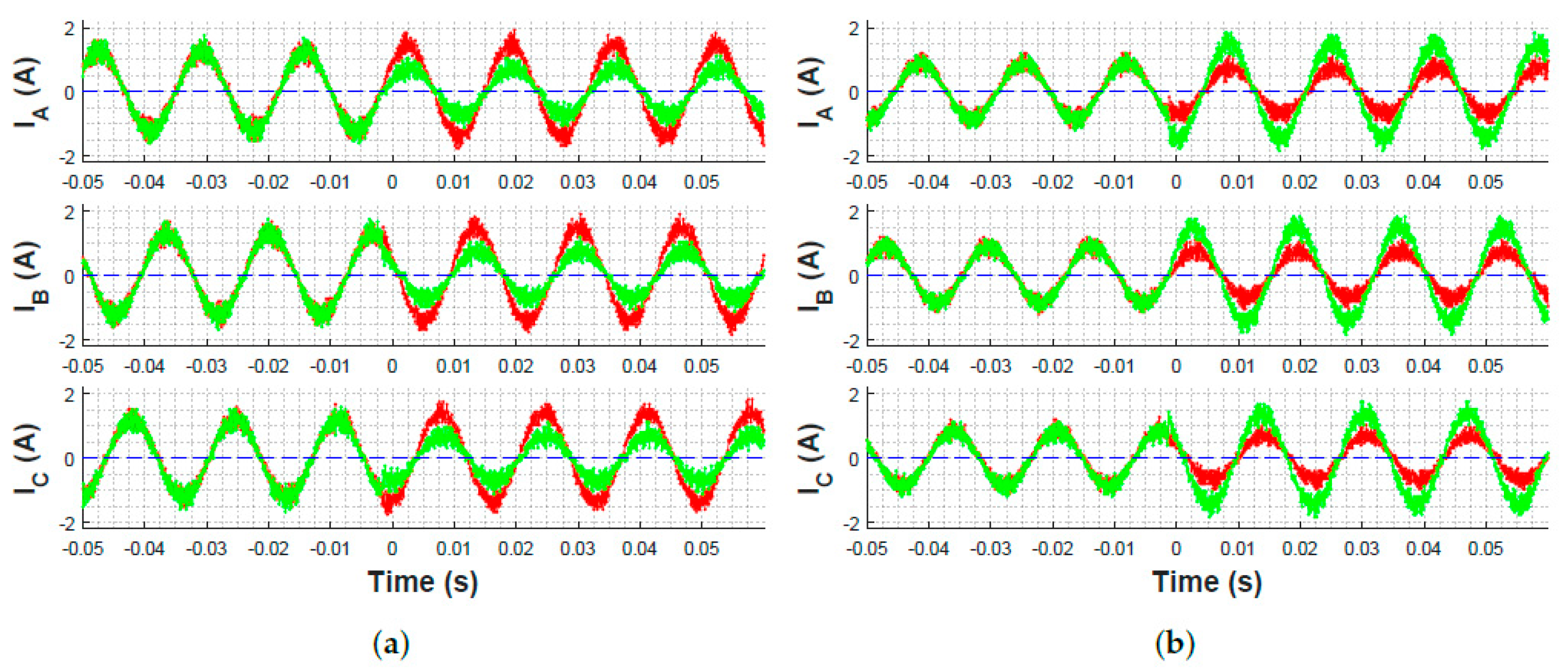
To demonstrate stability through rapid step-changes in load, two synchronized, identical inverters were equally sharing the load, and the load resistance was switched from a Y-connected to (66% decrease) on each phase, as shown in Figure 14a. These two inverters have identical virtual output impedance , and thus share load equally. They tolerate the change and maintain synchronization.
4.4. Inverter Load-Sharing Control through Manipulation of Virtual Output Impedance
One unique advantage of a current-controlled inverter is that the virtual output impedance can be manipulated during operation to change that inverter’s share of the load (Section 2.3). It was shown in [17] that the relative power contributions P of synchronized inverters under DZO control are related to the relative output impedances of the inverters j and k,
In Figure 15a, both inverters oscillate in synchronization with identical virtual output impedances until is doubled at time 0, increasing to twice . After is doubled, the output currents and continue to oscillate in phase but change magnitude, is approximately half of . This observation is consistent with (20). The opposite process, in which is halved rather than doubled, also yields the expected results in Figure 15b, with increasing to approximately twice .
This change in virtual output impedance does not affect the response to step changes in load. Figure 14b shows the same step change in load resistance ( to ) applied to inverters with unequal sharing such that the load-share of the first inverter is half that of the second inverter. It can be seen for both tests that the inverter output currents maintain both their relative amplitudes and their phase synchronization during a step change in load resistance. Recall that Figure 14a is the same test, but with identical virtual impedances .
5. Conclusions
This paper formulated and experimentally validated a method to bridge the gap between voltage-source and current-controlled converters for Virtual Oscillator Control applications. A virtual output admittance was used to allow a controller based on voltage output to interact with an amplifier based on a current command. If the current amplifier exhibits good command following at a bandwidth much higher than the base controller, the singular perturbations theorem allows the amplifier to be treated as an ideal current source. This paper showed that under these conditions, the dynamic behavior of the current-controlled amplifier oscillator system would match that of a voltage sourced amplifier. Simulations and hardware experiments demonstrated the effectiveness of this method for the basic oscillator performance, synchronization of multiple inverters, responses to load changes, and droop characteristics. The approach was also analyzed and simulated for cases when the amplifier has limited bandwidth. As expected, once the speed of the core oscillator dynamics approaches or exceeds the current control bandwidth, the behavior of the two implementations starts to diverge.
This VOC control was experimentally validated for the first time in a three-phase grid system with both voltage-source and current-controlled converters, and the voltage droop characteristics were verified to match predictions. The ability to tune the effective output impedances of current-controlled inverters was demonstrated by dynamically changing the load-share of parallel-connected inverters during operation. The particular variant tested, the dead-zone oscillator, demonstrated robustness to a 66% step-change in load was also with equal and unequal load-sharing. These results facilitate the deployment of VOC by extending it to three-phase and current-controlled inverter networks, and by demonstrating a new method of implementing load-sharing.
Author Contributions
Conceptualization, D.F.O.; Data curation, K.K., S.S. and S.P.; Formal analysis, D.F.O.; Investigation, K.K., S.S. and S.P.; Project administration, D.F.O.; Software, K.K., S.S. and S.P.; Supervision, D.F.O. and K.K.; Writing—original draft, D.F.O. and S.S.; Writing—review & editing, D.F.O. and K.K.
Funding
This work was partially supported by the United States Office of Naval Research under N0001415WX01739 and DURIP award N0001415WX02048.
Conflicts of Interest
The authors declare no conflict of interest. The funders had no role in the design of the study; in the collection, analyses, or interpretation of data; in the writing of the manuscript, or in the decision to publish the results.
References
- Trudnowski, D.; Donnelly, M.; Lightner, E. Power-System Frequency and Stability Control using Decentralized Intelligent Loads. In Proceedings of the 2006 IEEE/PES Transmission and Distribution Conference and Exhibition, Dallas, TX, USA, 21–24 May 2006; pp. 1453–1459. [Google Scholar]
- Dong, B.; Li, Y.; Zheng, Z.; Xu, L. Control strategies of microgrid with Hybrid DC and AC Buses. In Proceedings of the 2011 14th European Conference on Power Electronics and Applications, Birmingham, UK, 30 August–1 September 2011; pp. 1–8. [Google Scholar]
- Salehi, V.; Mohamed, A.; Mohammed, O.A. Implementation of real-time optimal power flow management system on hybrid AC/DC smart microgrid. In Proceedings of the 2012 IEEE Industry Applications Society Annual Meeting, Las Vegas, NV, USA, 7–11 Octorber 2012; pp. 1–8. [Google Scholar]
- Bidram, A.; Lewis, F.; Davoudi, A. Distributed Control Systems for Small-Scale Power Networks: Using Multiagent Cooperative Control Theory. IEEE Control Syst. 2014, 34, 56–77. [Google Scholar] [CrossRef]
- Kundur, P.; Klein, M.; Rogers, G.; Zywno, M.S. Application of power system stabilizers for enhancement of overall system stability. IEEE Trans. Power Syst. 1989, 4, 614–626. [Google Scholar] [CrossRef]
- Guerrero, J.M.; Vasquez, J.C.; Matas, J.; de Vicuna, L.G.; Castilla, M. Hierarchical Control of Droop-Controlled AC and DC Microgrids—A General Approach Toward Standardization. IEEE Trans. Ind. Electron. 2011, 58, 158–172. [Google Scholar] [CrossRef]
- D’Arco, S.; Suul, J.A.; Fosso, O.B. Automatic Tuning of Cascaded Controllers for Power Converters Using Eigenvalue Parametric Sensitivities. IEEE Trans. Ind. Appl. 2015, 51, 1743–1753. [Google Scholar] [CrossRef]
- D’Arco, S.; Suul, J.A. Equivalence of Virtual Synchronous Machines and Frequency-Droops for Converter-Based MicroGrids. IEEE Trans. Smart Grid 2014, 5, 394–395. [Google Scholar] [CrossRef] [Green Version]
- Torres, L.M.A.; Lopes, L.A.C.; Morán, T.L.A.; Espinoza, C.J.R. Self-Tuning Virtual Synchronous Machine: A Control Strategy for Energy Storage Systems to Support Dynamic Frequency Control. IEEE Trans. Energy Convers. 2014, 29, 833–840. [Google Scholar] [CrossRef]
- Moeini, A.; Kamwa, I. Analytical Concepts for Reactive Power Based Primary Frequency Control in Power Systems. IEEE Trans. Power Syst. 2016, 31, 4217–4230. [Google Scholar] [CrossRef]
- Alipoor, J.; Miura, Y.; Ise, T. Power System Stabilization Using Virtual Synchronous Generator with Alternating Moment of Inertia. IEEE J. Emerg. Sel. Top. Power Syst. 2015, 3, 451–458. [Google Scholar] [CrossRef]
- Sinha, M.; Dörfler, F.; Johnson, B.B.; Dhople, S.V. Virtual Oscillator Control subsumes droop control. In Proceedings of the 2015 American Control Conference (ACC), Chicago, IL, USA, 1–3 July 2015. [Google Scholar]
- Johnson, B.B.; Sinha, M.; Ainsworth, N.G.; Dörfler, F.; Dhople, S.V. Synthesizing Virtual Oscillators to Control Islanded Inverters. IEEE Trans. Power Electron. 2016, 31, 6002–6015. [Google Scholar] [CrossRef]
- Dörfler, F.; Chertkov, M.; Bullo, F. Synchronization in complex oscillator networks and smart grids. Proc. Natl. Acad. Sci. USA 2013, 110, 2005–2010. [Google Scholar] [CrossRef] [Green Version]
- Simpson-Porco, J.W.; Dörfler, F.; Bullo, F. Synchronization and power sharing for droop-controlled inverters in islanded microgrids. Automatica 2013, 49, 2603–2611. [Google Scholar] [CrossRef] [Green Version]
- Dörfler, F.; Bullo, F. Synchronization in complex networks of phase oscillators: A survey. Automatica 2014, 50. [Google Scholar] [CrossRef]
- Johnson, B.B.; Dhople, S.V.; Hamadeh, A.O.; Krein, P.T. Synchronization of Parallel Single-Phase Inverters With Virtual Oscillator Control. IEEE Trans. Power Electron. 2014, 29, 6124–6138. [Google Scholar] [CrossRef]
- Johnson, B.B.; Dhople, S.V.; Hamadeh, A.O.; Krein, P.T. Synchronization of Nonlinear Oscillators in an LTI Electrical Power Network. IEEE Trans. Circuits Syst. I 2014, 61, 834–844. [Google Scholar] [CrossRef]
- Johnson, B.B.; Dhople, S.V.; Cale, J.L.; Hamadeh, A.O.; Krein, P.T. Oscillator-Based Inverter Control for Islanded Three-Phase Microgrids. IEEE J. Photovolt. 2014, 4, 387–395. [Google Scholar] [CrossRef]
- Shabshab, S.C.; Opila, D.F. Extending control stability results from voltage-source to current-controlled AC or DC power converters. IFAC 2016, 49, 60–65. [Google Scholar] [CrossRef]
- Wang, X.; Li, Y.W.; Blaabjerg, F.; Loh, P.C. Virtual-Impedance-Based Control for Voltage-Source and Current-Source Converters. IEEE Trans. Power Electron. 2015, 30, 7019–7037. [Google Scholar] [CrossRef] [Green Version]
- Chowdhury, S.M.; Badawy, M.; Sozer, Y.; Garcia, J.A.D.A. A novel battery management system using a duality of the adaptive droop control theory. In Proceedings of the 2017 IEEE Energy Conversion Congress and Exposition (ECCE), Cincinnati, OH, USA, 1–5 Octorber 2017; pp. 5164–5169. [Google Scholar]
- Jin, Z.; Meng, L.; Han, R.; Guerrero, J.M.; Vasquez, J.C. Admittance-type RC-mode droop control to introduce virtual inertia in DC microgrids. In Proceedings of the 2017 IEEE Energy Conversion Congress and Exposition (ECCE), Cincinnati, OH, USA, 1–5 Octorber 2017; pp. 4107–4112. [Google Scholar]
- Zhang, W.; Remon, D.; Candela, I.; Luna, A.; Rodriguez, P. Grid-connected converters with virtual electromechanical characteristics: Experimental verification. CSEE J. Power Energy Syst. 2017, 3, 286–295. [Google Scholar] [CrossRef]
- Rodriguez, P.; Candela, I.; Citro, C.; Rocabert, J.; Luna, A. Control of grid-connected power converters based on a virtual admittance control loop. In Proceedings of the 2013 15th European Conference on Power Electronics and Applications (EPE), Lille, France, 2–6 September 2013. [Google Scholar] [CrossRef]
- Tarrasó, A.; Candela, J.I.; Rocabert, J.; Rodriguez, P. Grid voltage harmonic damping method for SPC based power converters with multiple virtual admittance control. In Proceedings of the 2017 IEEE Energy Conversion Congress and Exposition (ECCE), Cincinnati, OH, USA, 1–5 Octorber 2017; pp. 64–68. [Google Scholar]
- Jin, Z.; Meng, L.; Guerrero, J.M. Comparative admittance-based analysis for different droop control approaches in DC microgrids. In Proceedings of the 2017 IEEE Second International Conference on DC Microgrids (ICDCM), Nuremburg, Germany, 27–29 June 2017; pp. 515–522. [Google Scholar]
- Chandorkar, M.C.; Divan, D.M.; Adapa, R. Control of parallel connected inverters in standalone AC supply systems. IEEE Trans. Ind. Appl. 1993, 29, 136–143. [Google Scholar] [CrossRef] [Green Version]
- He, J.; Li, Y.W.; Guerrero, J.M.; Blaabjerg, F.; Vasquez, J.C. An Islanding Microgrid Power Sharing Approach Using Enhanced Virtual Impedance Control Scheme. IEEE Trans. Power Electron. 2013, 28, 5272–5282. [Google Scholar] [CrossRef]
- Guerrero, J.M.; de Vicuna, L.G.; Matas, J.; Castilla, M.; Miret, J. Output impedance design of parallel-connected UPS inverters with wireless load-sharing control. IEEE Trans. Ind. Electron. 2005, 52, 1126–1135. [Google Scholar] [CrossRef]
- He, J.; Li, Y.W. Analysis, Design, and Implementation of Virtual Impedance for Power Electronics Interfaced Distributed Generation. IEEE Trans. Ind. Appl. 2011, 47, 2525–2538. [Google Scholar] [CrossRef]
- Blanco, C.; Reigosa, D.; Vasquez, J.C.; Guerrero, J.M.; Briz, F. Virtual Admittance Loop for Voltage Harmonic Compensation in Microgrids. IEEE Trans. Ind. Appl. 2016, 52, 3348–3356. [Google Scholar] [CrossRef]
- Chen, Y.; Hesse, R.; Turschner, D.; Beck, H.P. Improving the grid power quality using virtual synchronous machines. In Proceedings of the 2011 International Conference on Power Engineering, Energy and Electrical Drives, Malaga, Spain, 11–13 May 2011; pp. 1–6. [Google Scholar]
- Chen, Y.; Hesse, R.; Turschner, D.; Beck, H.P. Comparison of methods for implementing virtual synchronous machine on inverters. In Proceedings of the International Conference on Renewable Energies and Power Quality, Santiago de Compostela, Spain, 28–30 March 2012; pp. 1–6. [Google Scholar]
- Guerrero, J.M.; Matas, J.; De Vicuna, L.G.; Castilla, M.; Miret, J. Wireless-Control Strategy for Parallel Operation of Distributed-Generation Inverters. IEEE Trans. Ind. Electron. 2006, 53, 1461–1470. [Google Scholar] [CrossRef] [Green Version]
- Guerrero, J.M.; Chandorkar, M.; Lee, T.L.; Loh, P.C. Advanced Control Architectures for Intelligent Microgrids—Part I: Decentralized and Hierarchical Control. IEEE Trans. Ind. Electron. 2013, 60, 1254–1262. [Google Scholar] [CrossRef]
- Guerrero, J.M.; Loh, P.C.; Lee, T.L.; Chandorkar, M. Advanced Control Architectures for Intelligent Microgrids—Part II: Power Quality, Energy Storage, and AC/DC Microgrids. IEEE Trans. Ind. Electron. 2013, 60, 1263–1270. [Google Scholar] [CrossRef] [Green Version]
- Baghaee, H.R.; Mirsalim, M.; Gharehpetian, G.B. Real-time verification of new controller to improve small/large-signal stability and fault ride-through capability of multi-DER microgrids. IET Gener. Transm. Distrib. 2016, 10, 3068–3084. [Google Scholar] [CrossRef]
- Baghaee, H.R.; Mirsalim, M.; Gharehpetan, G.B.; Talebi, H.A. Nonlinear Load Sharing and Voltage Compensation of Microgrids Based on Harmonic Power-Flow Calculations Using Radial Basis Function Neural Networks. IEEE Syst. J. 2018, 12, 2749–2759. [Google Scholar] [CrossRef]
- Khalil, H.K. Nonlinear Systems, 3rd ed.; Prentice Hall: Upper Saddle River, NJ, USA, 2002. [Google Scholar]
Figure 1.
Simple model of a voltage-source converter [20].
Figure 1.
Simple model of a voltage-source converter [20].
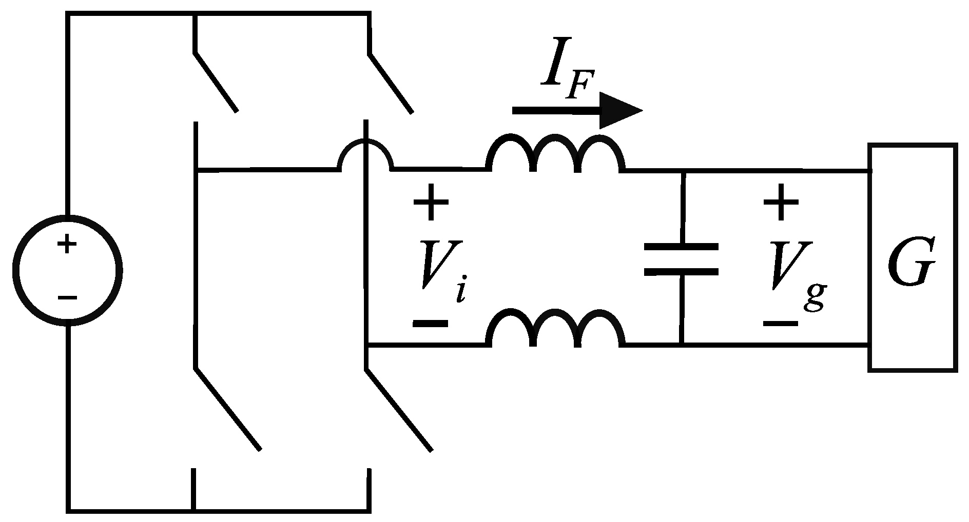
Figure 2.
The converter switches can be represented as an ideal voltage source. Series filter components are represented as , while parallel filter elements are lumped into the grid to become [20].
Figure 2.
The converter switches can be represented as an ideal voltage source. Series filter components are represented as , while parallel filter elements are lumped into the grid to become [20].
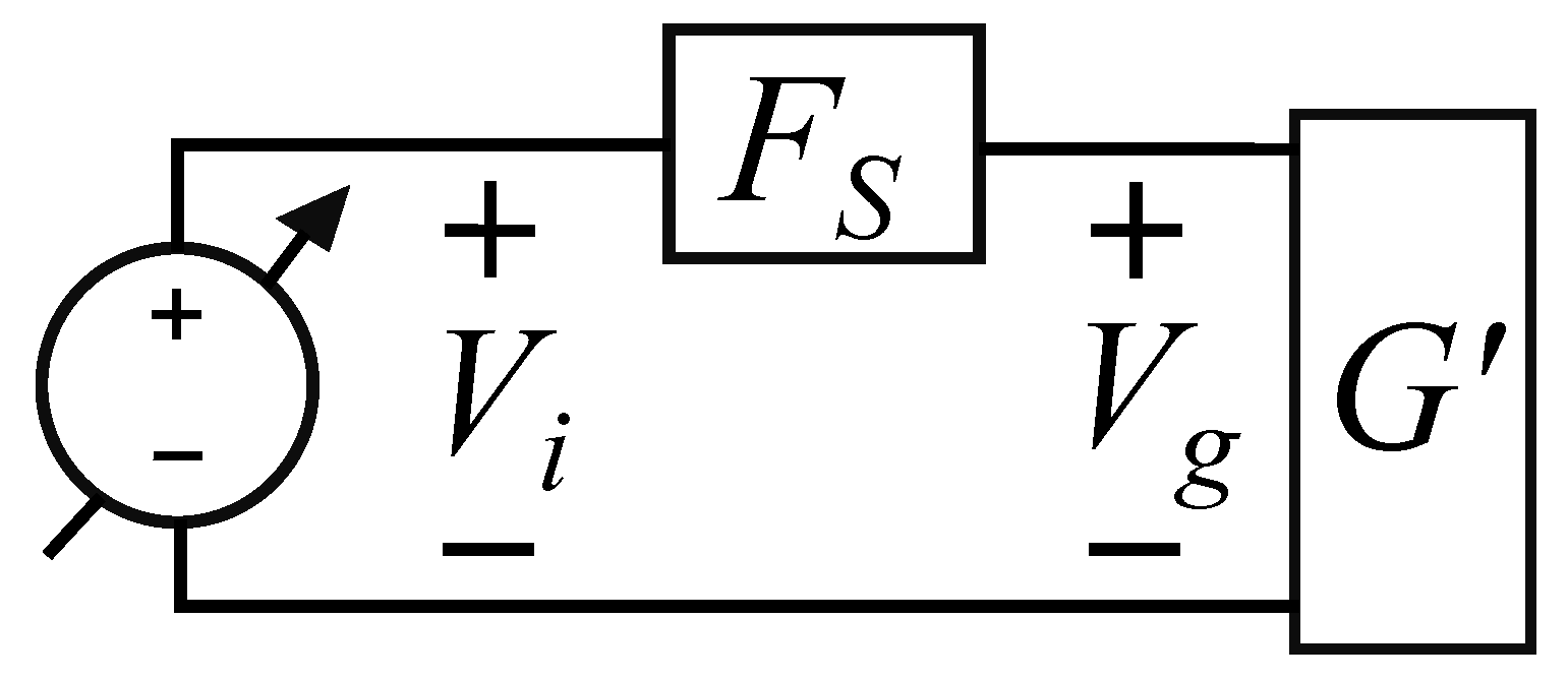
Figure 3.
A current-controlled inverter with a sufficiently fast PI loop can enforce any . Thus, given a simulated output voltage , it can enforce any virtual filter current (12). When the virtual and hardware filters do not match , the virtual () and real () inverter bridge terminal voltages will differ [20].
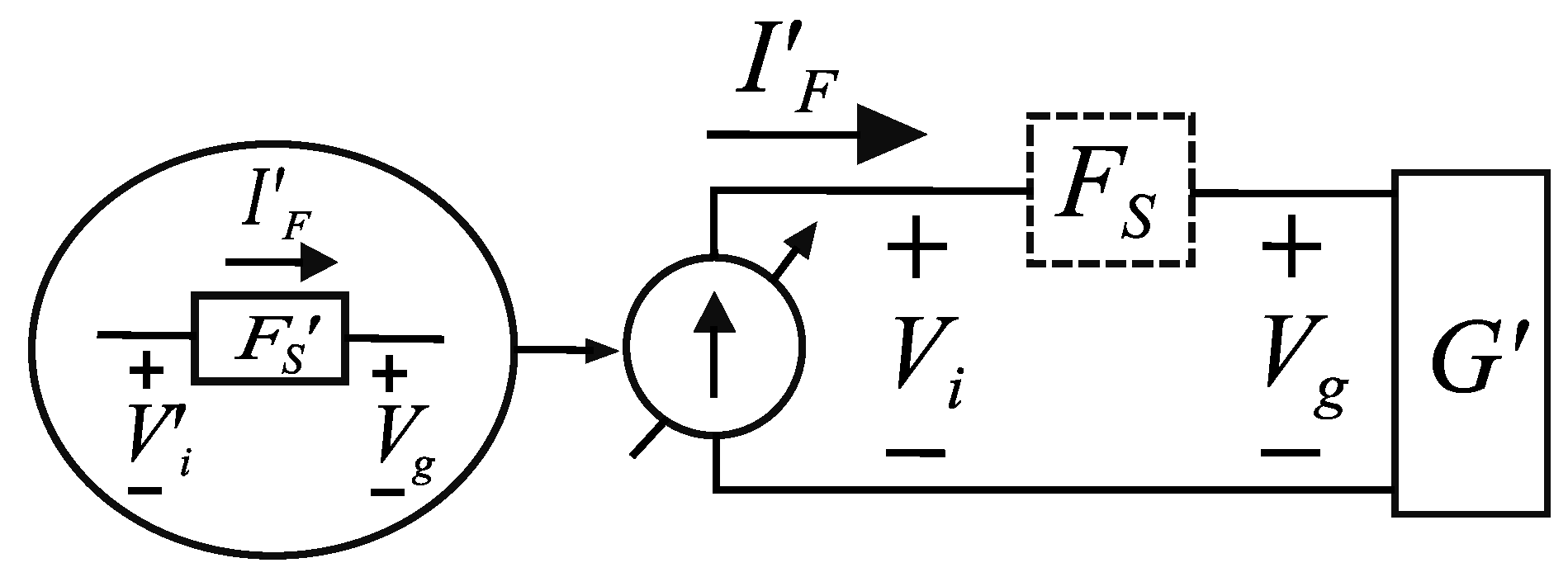
Figure 4.
Diagram of the output dynamics seen by the virtual oscillator for voltage-sourced and current-controlled systems. The oscillator controller C is not modified, and is shown with a dashed border. The remainder of the system is shown as a linear transfer function block diagram. The filter impedance is for the hardware filter or for the virtual filter. The grid (either G or ) is treated as its Thévenin equivalent with impedance and voltage . The current controller (e.g., a PI controller) is . The various impedances are all functions of s. (a) Voltage-sourced inverter block diagram. In the base derivation, the virtual oscillator control (VOC) controller C receives a current feedback measured at the inverter output. (b) Current-controlled inverter block diagram. In the base derivation, the VOC controller C receives a virtual current feedback based on the virtual filter. Alternatively, one could use the feedback of the actual current , shown as a dashed line.

Figure 5.
Circuit model of the Dead-Zone Oscillator. , the output of the voltage-dependent current source, is a nonlinear function . The impedance of the parallel resistor inductor capacitor (RLC) circuit, together with the parameters and of , control the limit cycle of a single oscillator and the interaction of coupled DZOs [17,20].

Figure 6.
One inverter subunit coupled to a Y-connected load. The inverter’s control signal reference and its negative DC rail are isolated. The negative DC power rail of each inverter floats in isolation. Each subunit’s controller reads and , the load voltages on phases A and B, and receives feedback of the amplifier output current. Additional inverter subunits are connected in parallel to the load for synchronization testing. The inverter can be either voltage-sourced and receive a voltage command, or current-controlled with a current command [20].

Figure 7.
One power converter subunit, as shown schematically in Figure 6. The testbed comprises three subunits connected in parallel to a Y-connected three-phase load. A DC source (not shown) feeds power to the inverter in the top left of the picture.
Figure 7.
One power converter subunit, as shown schematically in Figure 6. The testbed comprises three subunits connected in parallel to a Y-connected three-phase load. A DC source (not shown) feeds power to the inverter in the top left of the picture.
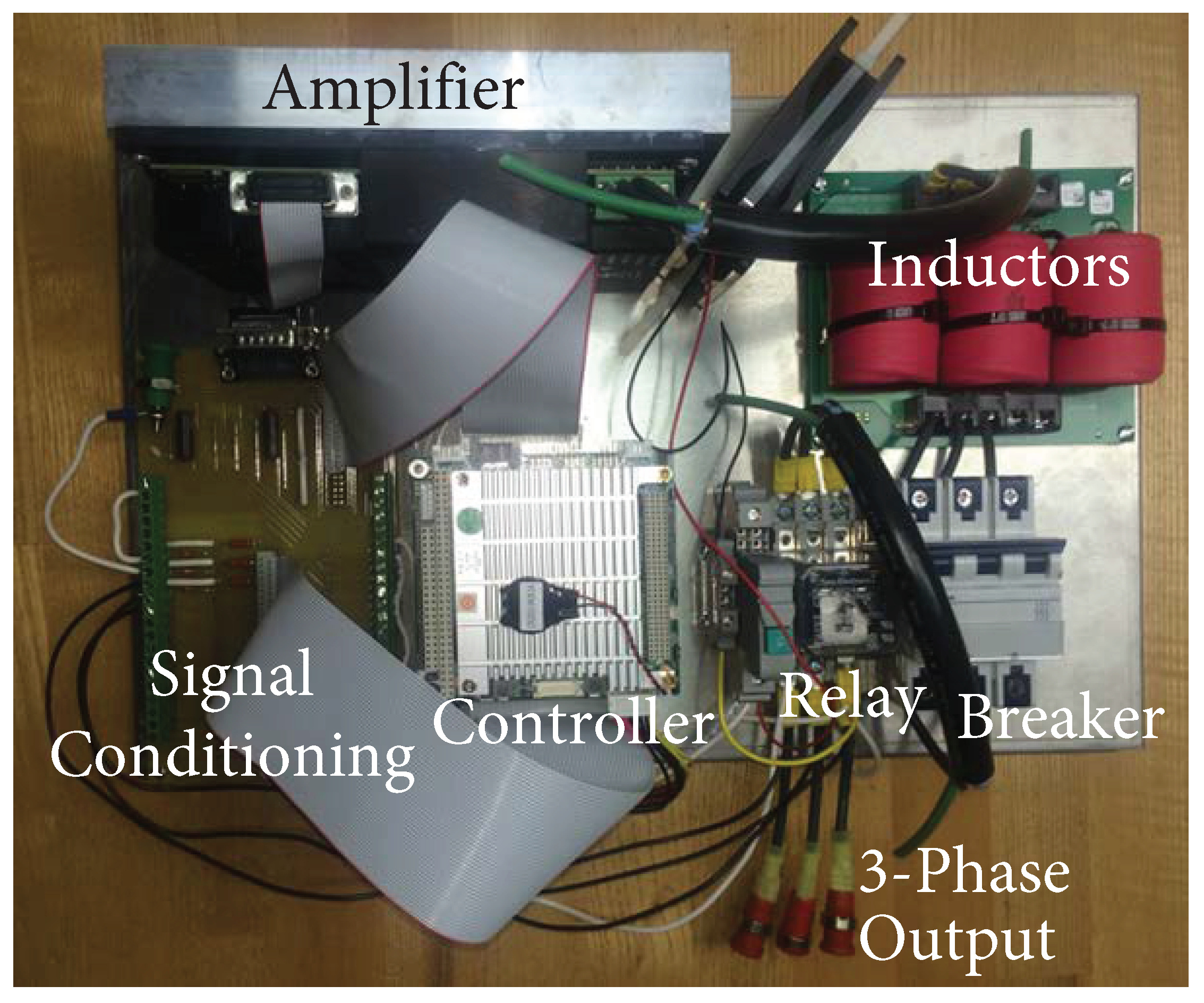
Figure 8.
Amplifier Bode plots in simulation and hardware for both voltage-sourced (VS) and current-controlled (CC) inverters. In all cases, the amplifier is connected through a 150 H inductor to a Y-connected resistive load. The voltage transfer function is measured as voltage command to current response, and scaled by the resistance () to produce 0 dB at low frequencies.

Figure 9.
Simulated startup transient for both voltage-sourced and current-controlled amplifiers operated by a DZO controller. They match almost exactly, as would be expected for operations within the bandwidth of the current controller. The phase of the traces diverge slightly over longer time intervals because the two systems are not completely identical.

Figure 10.
Simulated droop characteristics for voltage-sourced (VS) vs. current-controlled (CC) inverters for two different nominal ratings at 60 Hz and and one rating at 400 Hz. As expected, the two equivalent VS and CC formulations perform almost exactly the same for both ratings at 60 Hz, but they diverge at 400 Hz because it is beyond the current controller bandwidth shown in Figure 8. A derating by a factor of 25 is implemented by artificially scaling the current feedback to the oscillator, which creates a different droop characteristic [17,18,19].

Figure 11.
Experimental testing of a three phase voltage-sourced inverter which responds to step changes in load and synchronizes with another inverter. (a) Voltage-controlled inverter load resistance changes from to per phase resulting in transient response from the system with voltage and current overshoot. The DZO output then settles to nominal conditions. (b) Voltage-controlled inverter synchronizes when connected to another inverter.

Figure 12.
Three-phase voltage-controlled inverter droop characteristic demonstrated in simulation.

Figure 13.
Experimental testing of current-controlled converter synchronization with DZO control. (a) One current-controlled inverter synchronizes when connected to another inverter operating at rated power. (b) Current-controlled inverter synchronizes when connected to two already-synchronized inverters. Three traces are shown (red, green, blue), but the red trace is directly under the green because they are already synchronized. A maximum load phase current of 4.64 A and a maximum inverter phase current of 8.48 A were observed in testing [20].

Figure 14.
Hardware testing of two synchronized current-controlled inverters, with both equal and unequal load-sharing, that maintain their behavior through a step increase in load. Load resistance changes from 2.2 to 0.733 [20]. (a) Inverters with equal power sharing. (b) Inverters with unequal power sharing.
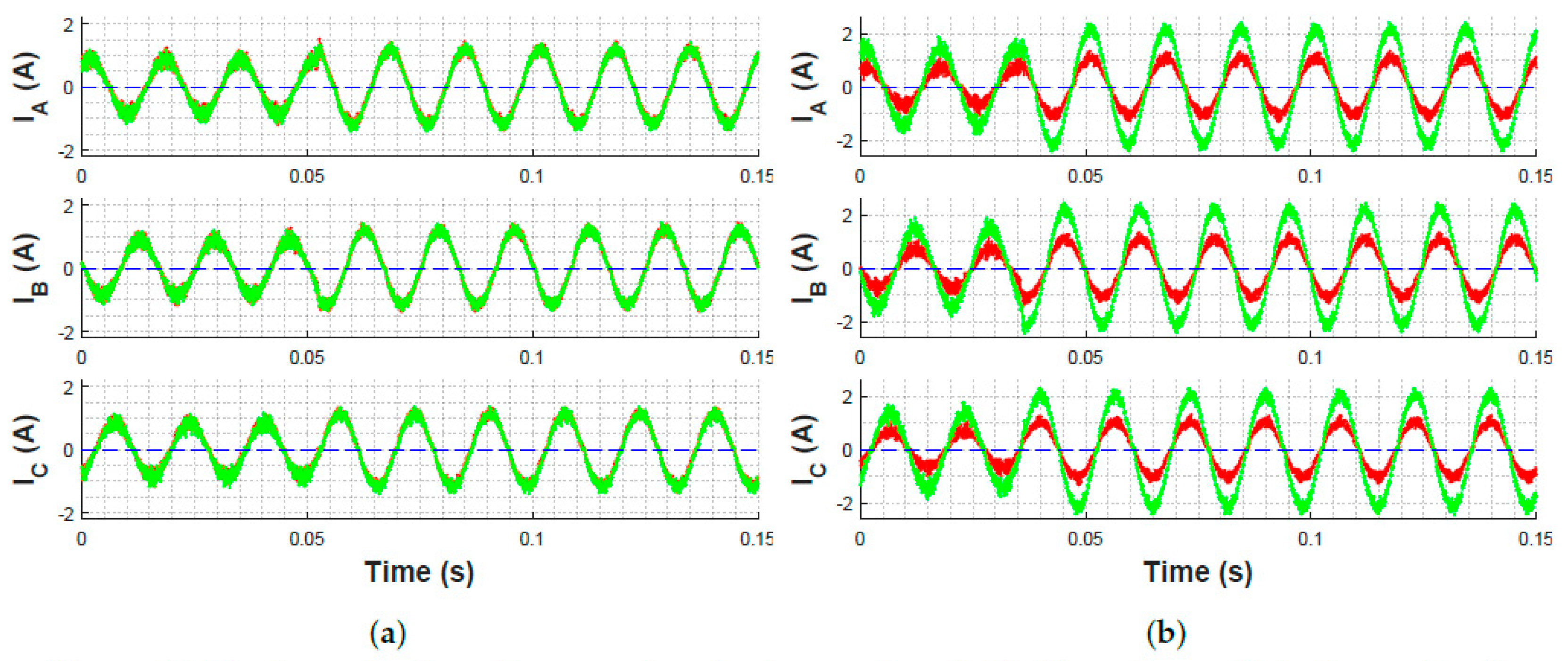
Figure 15.
Experimental three phase test cases demonstrate the ability to control load sharing between two different current-controlled inverters by changing the virtual output impedance of one of them [20]. (a) The load carried by one inverter is decreased by increasing virtual output impedance. (b) The load carried by one inverter is increased by decreasing virtual output impedance.

© 2019 by the authors. Licensee MDPI, Basel, Switzerland. This article is an open access article distributed under the terms and conditions of the Creative Commons Attribution (CC BY) license (http://creativecommons.org/licenses/by/4.0/).
Share and Cite
MDPI and ACS Style
Opila, D.F.; Kintzley, K.; Shabshab, S.; Phillips, S. Virtual Oscillator Control of Equivalent Voltage-Sourced and Current-Controlled Power Converters. Energies 2019, 12, 298. https://doi.org/10.3390/en12020298
AMA Style
Opila DF, Kintzley K, Shabshab S, Phillips S. Virtual Oscillator Control of Equivalent Voltage-Sourced and Current-Controlled Power Converters. Energies. 2019; 12(2):298. https://doi.org/10.3390/en12020298
Chicago/Turabian StyleOpila, Daniel F., Keith Kintzley, Spencer Shabshab, and Stephen Phillips. 2019. "Virtual Oscillator Control of Equivalent Voltage-Sourced and Current-Controlled Power Converters" Energies 12, no. 2: 298. https://doi.org/10.3390/en12020298
Note that from the first issue of 2016, this journal uses article numbers instead of page numbers. See further details here.