Energy Routing Control Strategy for Integrated Microgrids Including Photovoltaic, Battery-Energy Storage and Electric Vehicles

School of Electrical and Electronic Engineering, North China Electric Power University, Baoding 071003, China
*
Author to whom correspondence should be addressed.
Energies 2019, 12(2), 302; https://doi.org/10.3390/en12020302
Submission received: 30 November 2018
/
Revised: 8 January 2019
/
Accepted: 15 January 2019
/
Published: 18 January 2019
(This article belongs to the Special Issue Power Electronics in Renewable Energy Systems)
Abstract
:The Energy Internet is an inevitable trend of the development of electric power system in the future. With the development of microgrids and distributed generation (DG), the structure and operation mode of power systems are gradually changing. Energy routers are considered as key technology equipment for the development of the Energy Internet. This paper mainly studies the control of the LAN-level energy router, and discusses the structure and components of the energy router. For better control of the power transmission of an energy router, the energy routing control strategy for an integrated microgrid, including photovoltaic (PV) energy, battery-energy storage and electric vehicles (EVs) is studied. The front stage DC/DC converter of the PV system uses maximum power point tracking (MPPT) control. The constant current control is used by the bidirectional DC/DC converter of the battery-energy storage system and the EV system when they discharge. The DC/AC inverters adopt constant reactive power and constant DC voltage control. Constant current constant voltage control is adopted when an EV is charged. The control strategy model is simulated by Simulink, and the simulation results verify the feasibility and effectiveness of the proposed control strategy. The DG could generate reactive power according to the system instructions and ensure the stable output of the DC voltage of the energy router.
1. Introduction
In the third industrial revolution, Rifkin, an American economist, proposes the concept of Energy Internet and mainly describes the application of the Energy Internet in the future [1,2], which has drawn worldwide attention and studies [3,4]. With the continuous development of Internet+, microgrid, renewable energy and DG, the structure and operation mode of the traditional power system are gradually changing [5,6,7].
The Energy Internet is a new generation of intelligent network, having electric power information as its core. The energy domain and information technologies interact with each other and then make efficient use of different energy sources [8,9,10]. The Energy Internet is characterized by networking and distribution, and various international research organizations have done a lot of research works based on different needs and conditions. Germany has proposed the concept of E-Energy and the Energy Internet plan, and studied the system design and management mode [11]. The Future Renewable Electric Energy Delivery and Management (FREEDM) has proposed the concept of energy router and designed energy routers based on solid state transformers (SSTs). The energy router is considered as the infrastructure for building the future energy Internet [12]. Japan’s “Digital Power Grid Alliance” manages and dispatches the electric energy in the corresponding region based on a “Digital Power Grid Router” [13]. In China’s Energy Internet project, the large power grid is regarded as the backbone WAN and the microgrid as the local area network LAN. All components are connected through integrated information energy switching equipment [14]. Almost all of the above Energy Internet prototypes contain energy routers or power routers, indicating that energy routers are one of the key technologies of the Energy Internet [15,16]. Therefore, the Energy Internet is also defined as a multi-level distributed energy sharing complex network based on energy routers and energy LANs (units) with the microgrid as its basic structure [17]. The Energy Internet architecture based on energy routers is shown in Figure 1.
As the main component of the Energy Internet, the energy router has comprehensive functions such as energy-exchange, communication and energy management [18]. At present, energy router research is still in a primary stage. The aim of this paper is to study the control of a LAN-level energy router. This paper discusses the structure and compositions of the energy router, and focuses on the energy transmission control strategy of the energy router for different distributed generations, such as PV, battery-energy storage and EVs. The energy routing models of PV, energy storage and EVs are established and simulated by Simulink. The simulation results verify the feasibility and effectiveness of the proposed control strategy. The DG could generate reactive power according to the system instructions and ensure the stable output of the DC voltage of the energy router. The structure of the paper is as follows: in Section 2, related work is presented. The architecture of the energy router is described in Section 3. The energy routing control strategy is described in Section 4. The simulation and results are presented in Section 5. Finally, Section 6 gives the conclusions.
2. Related Work
At present, energy router research is still in a primary stage. In [19], a distributed power routing control strategy based on the Dijkstra algorithm method for the management and coordination control of power flow in energy routers was put forward. A three-layer tree architecture of an intelligent distributed energy network based on the multi-energy router concept is drawn in [20], where the typical characteristics of the energy router are summarized and analyzed. In [21], the authors presented the main circuit structure of a multi-interface energy router based on a power electronic converter and introduce the control strategy of each module of an energy router. A distributed energy router is designed in [22] and its control mode is designed to ensure the stability of AC and DC buses. However, different DGs have different characteristics and requirements. The common DGs are wind power, PV, energy storage and EVs [23,24]. The PV power generation has the characteristics of randomness, volatility and weak reactive power support [25]. Theories show that distributed energy storage is an effective approach to solve the problems of PV mentioned above [26,27]. EVs are controllable in time and mobile in space. They could be used as micro sources (V2G) to release electric energy. They could also be used as a load (charging), which is inserted into the grid to store electricity [28,29,30]. In fact, energy routers need to ensure the normal operation and quality of the power grid, but it is also important to ensure the reasonable flow of distributed energy, meet the load demand and control the correct and safe energy flow intelligently.
This paper mainly studies the control of a LAN-level energy router, discusses the structure and compositions of the energy router, and focuses on the energy transmission control strategy of the energy router for different distributed generations, such as PV, battery-energy storage and EVs.
3. The Architecture of the Energy Router
Since the development trend of energy routers is to combine the energy interface layer of the unified regional energy LAN with the distributed generation, the energy router needs various types of energy input interfaces and corresponding control loops. The architecture of an energy router is shown in Figure 2.
The energy router can be divided into three parts: the control part, the energy transmission loop and the Internet communication unit. The energy router network information unit has the functions of receiving Internet information, collecting and processing data, data analysis, prediction, interaction and decision-making. The energy transmission layer and control part work according to different requirements. The three parts interact and ultimately achieve high efficiency and safety of energy utilization.
In terms of the energy routing control, different control methods are adopted for different DGs. The PV system uses the unidirectional DC/DC converter to achieve one-way flow of power, at the same time to realize MPPT. A bidirectional DC/DC converter is used for the battery-energy storage system and EV system when they discharge. The DC/AC inverter of the AC side adopts constant reactive power and constant DC voltage control, which enables the PV, battery-energy storage and EVs to generate reactive power according to the grid instructions and ensure stable output of DC voltage of energy router. The constant current constant voltage control is adopted when an EV is charged. The energy routing models of PV, energy storage and the EVs are established and simulated based on Simulink.
4. The Energy Routing Control Strategy
4.1. EV and PV Battery-Energy Storage Power System
In order to study the energy routing strategy for the integrated microgrid, including PV, battery-energy storage and EVs, their structures are designed in this paper as shown in Figure 3, which includes a PV system, battery-energy storage system, EV system, load and the inverter control systems of each system.
In Figure 3, , and , are the switches and diodes. , , are the boost/buck circuit inductances of the PV system, energy storage system and EV system, respectively. , , are their DC capacitances, respectively. , , are the DC voltages. The is the boost circuit capacitances of PV. , , are the converter reactors. Load1, Load2, Load3 are the loads of system. , , , , and are the currents of the diode and DC capacitances. , , are the grid-connected capacitors and inductances.
4.2. Energy Routing Control Strategy of PV System
The power generation control system of PV is divided into two control subsystems, which are unidirectional DC/DC and DC/AC, respectively. The control goals of PV system are to achieve the MPPT operation of the PV array, stabilize the converter DC voltage and output reactive power according to the system instruction.
4.2.1. Unidirectional DC/DC Control Strategy
The front-stage converter of the PV power generation control system adopts unidirectional DC/DC control to realize one-way power flow and simultaneously realize MPPT control. The DC/DC converter realizes input and output voltages control by adjusting the duty cycle of insulated-gate bipolar transistor (IGBT). The principle of PV front-stage DC/DC control is shown in Figure 4. IPV is the current of PV array, VPV is the DC voltage of the PV array.
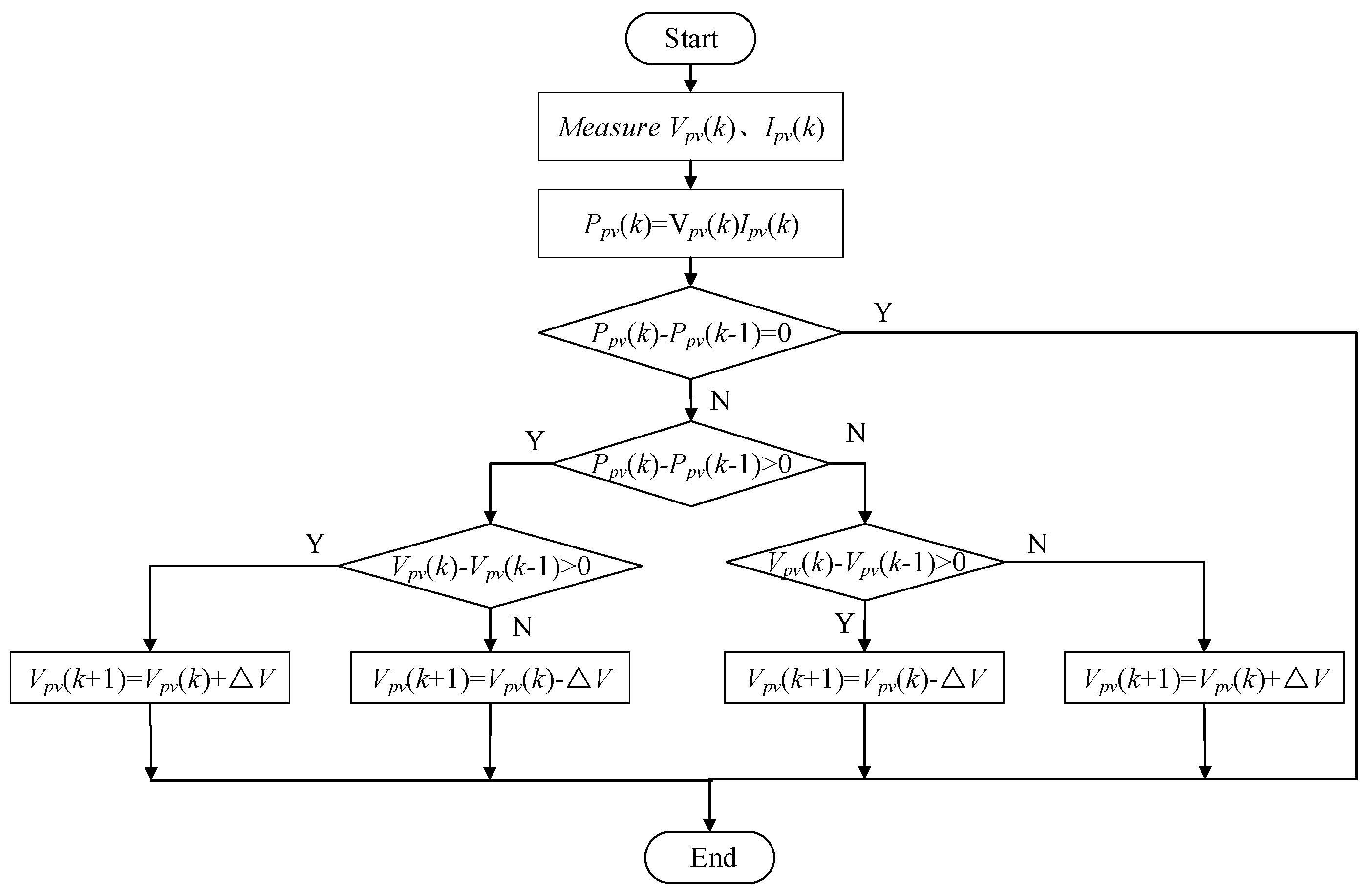
MPPT refers to the tracking and control of DGs, so that the maximum power output can be obtained in all circumstances. The common MPPT methods of PV arrays are the constant voltage method, disturbance observation method, and incremental conductance method. There is a maximum power point when a PV array operates under certain conditions. The main principle of the disturbance observation method is to apply a periodic constant step disturbance to the output voltage of PV array ∆V (or a constant step disturbance to the output current of the PV array ∆I). If the ∆P is positive, it means the working point voltage is less than the maximum power point voltage, and the disturbance in the original direction will continue to increase. Otherwise, the working point voltage will be larger than the maximum power point, and a negative direction will be added. The working point of the PV cell will be kept close to the MPPT. In this paper, the PV power generation system uses disturbance observation which is the most commonly used method.
In this way, by referring to a self-optimizing search program, which is shown in Figure 5, the constant step length disturbance is added to the PV output voltage. The change of current and pre-change power is compared in real time, so that PV array can work at the maximum power point as much as possible.
4.2.2. DC/AC Control Strategy
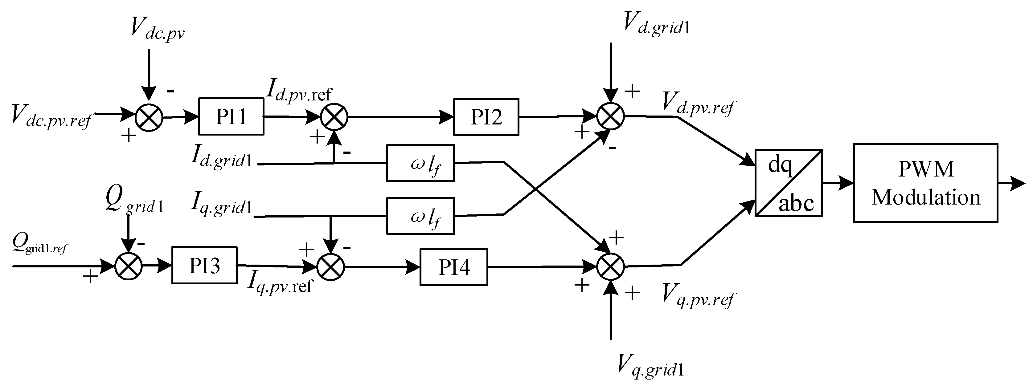
In Figure 6, the PV power generation inverter adopts double loop control, the outer ring is constant DC voltage and constant reactive power control, the inner ring is current control. Vq.grid.ref and Vd.grid.ref are respectively the instruction values of the d and q axis components of the grid side voltage. Vdc.pv is the output voltage actual value of the unidirectional DC/DC converter of PV, Qgrid1 is the reactive power actual value of the grid. They are the input of outer ring value of the inverter control system, and are compared respectively with the DC voltage instruction value of PV Vdc.pv.ref and network side reactive power instruction value Qgrid1.ref.
The input current instruction value of PV Id.pv.ref and Iq.pv.ref are obtained through the outer loop proportional integral (PI) controller for synchronous rotating coordinate system under the current inner loop controller. After coordinate transformation, the d, q components of the grid side DC current Id.grid1 and Iq.grid1 are obtained, and they are compared with their instruction value of corresponding current d and q components Id.grid1.ref and Iq.grid1.ref. The six PWM trigger pulses are obtained through PI controller and PWM modulation of the inner loop. Finally, IGBT is controlled to realize non-static adjustment of constant DC voltage and constant reactive power. The space vector pulse width modulation (SVPWM) modulation is adopted in this paper, and inductance capacitance (LC) filtering method is used to suppress the current harmonic generated by it in order to make it work normally.
4.3. Energy Routing Control Strategy of Battery-Energy Storage System
The battery-energy storage power generation control system is divided into two control subsystems, which are bidirectional DC/DC converter and DC/AC inverter. Its goals are:
- achieving two-way flow of power in battery-energy storage system
- achieving constant reactive power control
- achieving constant DC voltage control
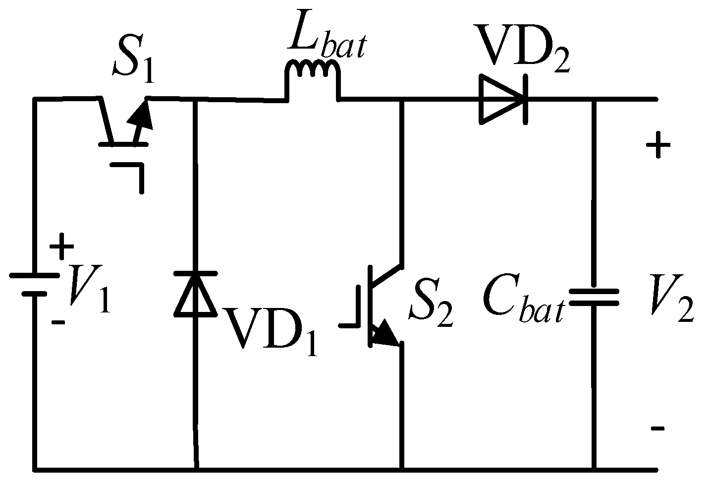
In Figure 7, the front stage converter of energy storage adopts directional DC/DC, which could increase the voltage or decrease the voltage. It is mainly composed of the inductance Lbat, capacitor Cbat, IGBT switches S1, S2, diode VD1 and VD2.
By controlling the conduction ratio of PWM to achieve its switches on and off. The output voltages, the duty ratio of the two switch tubes are set as V1, V2 and D1, D2 respectively, the relation of them as shown in Equation (1):
When the charge-discharge current instruction value Ibat.ref shown in Figure 6 is positive, the bidirectional DC/DC is in the boost state. Otherwise, the bidirectional DC/DC is in the buck state.
Figure 8 is the schematic diagram of the battery-energy storage control system. It consists of a bidirectional DC/DC converter control and inverter control. The principle of the bidirectional DC/DC control has been explained previously, the inverter is controlled by dual closed-loop control of voltage and current.
Vdc.bat is the actual DC voltage on the DC side of the inverter of the battery-energy storage system, Qgrid2 is the actual reactive power on the grid side of the grid. They are respectively controlled by the voltage outer ring and the power outer ring, and then the instruction values of d and q axis of current control Id.bat.ref and Iq.bat.ref are obtained. The current collected by the grid Il is transformed through coordinate transformation to obtain DC/AC inverter of d and q components of AC side current Id.l, Iq.l. The Id.l and Iq.l are compared with Id.bat.ref and Iq.bat.ref, respectively, and the PWM trigger pulse is obtained through the current controller, which ensures the non-static adjustment of DC voltage/reactive power.
4.4. Energy Routing Control Strategy of EVs
When the EV is a micro source (V2G), it adopts the same control strategy as a battery-energy storage control system, with bidirectional DC/DC control at the front stage and constant DC voltage constant reactive power of DC/AC inverter control at the after stage.
At present, lithium ion batteries are widely used in EVs. When the EV in this paper is used as system load (charging), its charging control mode needs to consider the characteristics of lithium ion batteries. The control purposes of EV charging machines are to improve the charging efficiency of the battery, shorten the charging time and extend the battery service life. As we all know, shortening the charging time will lead to a sharp decline in battery life, therefore, the charging time and battery life of EV should be considered comprehensively. This control strategy, mainly including AC/DC inverter voltage stability control, DC/DC buck chopper constant current control and DC/DC buck chopper constant voltage control, is shown in Table 1.
The control principle of the AC/DC inverter is same as that of discharge. Two different control modules of constant current and constant pressure are established on the DC/DC control side respectively. The switching of constant current and constant voltage charging mode is realized according to the battery terminal voltage. The current loop PI control is adopted in the constant current stage. By changing the duty cycle ratio, the on-off of the switch tube is controlled and the output current is kept constant. The control structure of the inverter is shown in Figure 9.
Constant voltage control adopts double closed loop control of the external power battery terminal voltage and internal inductance current. The current inner loop is to control according to the current instruction output by the voltage of the outer loop, and improve the dynamic response of the system. The outer voltage loop is used to maintain the stability of the power battery terminal voltage. The inverter control structure shown in Figure 10.
5. Simulation and Results
In order to verify the effectiveness of the control strategy proposed in this paper, a simulation study is carried out. In this paper, a complete simulation structure diagram of the energy routing control of the PV, battery-energy storage and EV system is built under Simulink. The simulation parameters are shown in Table 2, Table 3 and Table 4.
5.1. Example 1: The Reactive Power Instruction Values of PV, Battery-Energy Storage and EV Are all 0 Var
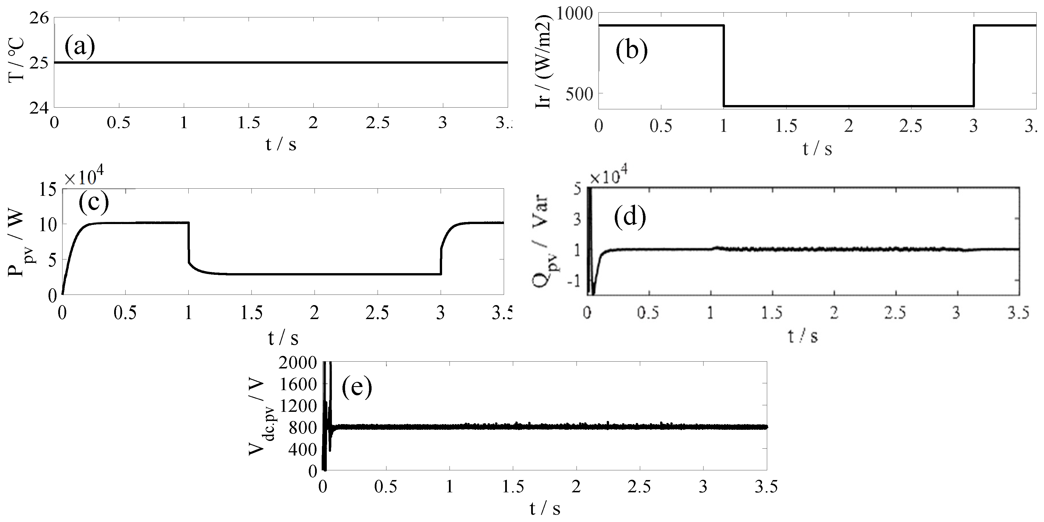
Figure 11 shows the PV simulation results when the reactive power instruction values of PV, battery-energy storage and EV are all 0 Var. As seen in Figure 11a, the initial temperature of the PV array is stable at about 25 °C. As depicted in Figure 11b, the light intensity of the PV array decreases at around 1s and increases back to the original state at around 3 s.
In Figure 11c, the active power output of PV array has the same change trend, falling at around 1 s and increasing back to the original state at around 3 s. Therefore, the PV array has realized the MPPT operation under the control of DC/DC. The variation of active power output is smooth and this reduces the impact on the system. The reactive power of the AC side of the PV inverter is stable at 0 Var as shown in Figure 11d. Figure 11e shows that the DC voltage of the inverter can be stabilized at around 800 V, which is the same as the instruction value of the grid side. As a power grid power source, PV has characteristics of uncertainty and randomness. The constant reactive power and constant DC voltage control strategy of DC/AC inverter used in this paper, is able to achieve the function of releasing reactive power according to the power grid instructions, stabilizing DC voltage and stabilizing the active power.
Figure 12a–f are the battery-energy storage results. The reactive power of the battery-energy storage could well track its instruction value shows Figure 12b, which is about 0 Var. As shown in Figure 12c, the DC voltage at the inverter side could track well its instruction value that is 800 V. The active power of it could stabilize the output as shown in Figure 12a. As depicted in Figure 12d–f, the bidirectional DC/DC converter of battery-energy storage adopts the constant current discharge control method, and the discharge current is basically kept at around 112 A as shown in Figure 12d. The discharge voltage is slightly reduced is shown in Figure 12e and the charge capacity of the battery decreases uniformly is shown in Figure 12f. The battery-energy storage could be controlled by constant DC voltage constant reactive power and the mode of constant current, which can realize stable output of the reactive power and active power, thus ensure the stable operation of the power grid. Figure 12g–i are the simulation results of EV. It can be seen that under the control of constant reactive power and constant DC voltage of energy router, EV could also be connected to the network stably.
Figure 13 shows the active and reactive power generated by the grid. The active and reactive load of this system are respectively 0.06 MW and 0.06 MVar. The active power generated by the grid makes up for the demand of active power load as shown in Figure 13a Since the reactive power instruction values of the DG are all 0 Var, the reactive power of the system is provided by the grid, as shown in Figure 13b.
5.2. Example 2: The Reactive Power Instruction Values of PV, Battery-Energy Storage and EV Are Respectively 10,000 Var, 20,000 Var and 0 Var
Figure 14 shows the PV simulation results. The reactive power instruction values of the PV, battery-energy storage and EV are respectively 10,000 Var, 20,000 Var, and 0 Var. As shown in Figure 14a, the initial temperature of the PV array is stable at about 25 °C.
As depicted in Figure 14b, the light intensity of the PV array decreased at around 1 s and increased back to the original state at around 3 s. In Figure 14c, the active power output of the PV array has the same change trend, and falls at around 1 s and increases back to the original state at around 3 s, therefore the PV array has realized the MPPT operation under the control of DC/DC. The variation of active power output is smooth and reduces the impact on the system. The reactive power of the AC side of the PV inverter is stable at 10,000 Var, as shown in Figure 14d. Figure 14e shows that the DC voltage of the inverter can be stabilized at around 800 V, which is the same as the reactive power and DC voltage instruction value of the grid side. As a power source of the power grid, PV has characteristics of uncertainty and randomness. The constant reactive power constant DC voltage control strategy of DC/AC inverter used in this paper can achieve the function of releasing reactive power according to the instruction of power grid, stabilizing DC voltage, and then stabilizing the active power.
Figure 15a–f are the battery-energy storage results. As shown in Figure 15b the reactive power of the battery-energy storage could track well its instruction value, which is about 20,000 Var. As shown in Figure 15c, the DC voltage at the inverter side could track well its instruction value, which is 800 V. The active power could be stabilized as shown in Figure 15a. The bidirectional DC/DC converter of battery-energy storage adopts the constant current discharge control method, the discharge current is basically kept at around 115 A as shown in Figure 15d, the discharge voltage is slightly reduced as shown in Figure 15e and the charge capacity of the battery decreases uniformly as shown in Figure 15f. The battery-energy storage could generate stable reactive power and active power, which ensure the stable operation of the power grid under the control of constant DC voltage constant reactive power and the mode of constant current. Figure 15g,h are the EV simulation results where the reactive power of the EV is about 0 Var and the DC voltage of the EV is about 800 V which are the same as their instruction values. It can be seen that under the control of constant reactive power constant DC voltage of energy router, the EV could be connected as a distributed power source to the grid and ensure the stability of the power grid.
Figure 16 shows the active and reactive power generated by the grid. The active and reactive load of this system are respectively 0.06 MW and 0.06 MVar. The active power generated by the grid makes up for the demand of active power load as shown in Figure 16a. Since the reactive power instruction values of the DG are respectively 10,000 Var, 20,000 Var, 0 Var., the rest of the reactive power of the system is provided by the grid. As shown in Figure 16b, the reactive power of grid is about 30,000 Var.
5.3. Example 3: EV Charging
Figure 17 shows the simulation results of the EV when it is the load of the grid. The constant current and constant voltage are adopted when the EV is charged. The constant current charging current is 10 A, and the constant voltage charging voltage is 440 V. It can be seen from Figure 17a,b, that a constant current is adopted at the beginning stage, and this constant current is 110 A. With the deepening of charging, the battery voltage gradually increases to 440 V, and the charging machine is switched to the constant voltage charging mode. The constant current charging time is 8 s. After 8 s, the terminal voltage of the power battery remains at 440 V, the charging current gradually decreases and enters the trickling charging stage. The battery continues to be charged. It can be seen from Figure 17c,d that the charge capacity of the power battery increases faster in the constant current stage, while the charge capacity increases slowly in the constant voltage stage due to the reduction of charging current. The intermediate voltage of AC/DC inverter remains stable after charging, which verifies the effectiveness of the control strategy of constant voltage and constant current charging of the power battery.
6. Conclusions
This paper mainly studies the control of a LAN-level energy router, discusses the structure and components of the energy router, and focuses on the energy transmission control strategy of the energy router for different distributed generations. The models of EV, PV and battery-energy storage are established respectively by using Simulink. Three examples are simulated to verify the effectiveness of the control strategy. The examples are the reactive power instruction values of DGs are all 0 Var; the reactive power instruction values of PV, battery-energy storage and EV are respectively 10,000 Var, 20,000 Var and 0 Var; and EV charging.
The simulation results show that the control method of the PV system could realize MPPT, and the EV system could achieve constant voltage and constant current control when it is charging. The EV, PV and battery-energy storage could release reactive power according to the instructions of the grid. The DC voltages of DGs could be well controlled and stabilized. The normal operation and quality of the power grid be achieved under the control of the energy router while maintaining the reasonable flow of distributed energy and safe intelligent energy flow. The limitation of this work is that the control model of the energy router lacks any interaction with the communication and decision-making part of the power system. In fact, the control of the energy router needs to interact with the communication part in real time, which can be further studied and combined in the future.
Author Contributions
Conceptualization, Y.L. (Yingpei Liu) and Y.L. (Yan Li); Funding acquisition, Y.L. (Yingpei Liu) and H.L.; Methodology, Y.L. (Yingpei Liu), Y.L. (Yan Li) and H.L.; Software, Y.L. (Yan Li), H.L., J.H. and H.C.; Validation, Y.L. (Yingpei Liu), Y.L. (Yan Li), H.L., J.H. and H.C.; Writing—original draft, Y.L. (Yingpei Liu), Y.L. (Yan Li) and H.L.; Writing—review & editing, Y.L. (Yingpei Liu), Y.L. (Yan Li), H.L., J.H. and H.C.
Funding
This research was funded by the Project Supported by National Natural Science Foundation of China, grant number 51607069 and the Fundamental Research Funds for the Central Universities, grant number 2016MS88; 2017MS091.
Acknowledgments
An earlier version of this paper was presented at 2018 IEEE International Conference on Information, Communication and Engineering. The authors would like to express their sincere gratitude to IEEE ICICE 2018 committees for recommending it to submit to Energies.
Conflicts of Interest
The authors declare no conflict of interest.
References
- Liang, H.; Li, Y.; Liu, Y.; He, J.; Cui, H. Grid-connected Control Strategy of PV Battery-energy Storage Hybrid Power System with Electric vehicle. In Proceedings of the 2018 IEEE International Conference on Information, Communication and Engineering, Xiamen, China, 28–30 September 2018. [Google Scholar]
- Rifkin, J. The Third Industrial Revolution: How Lateral Power Is Transforming Energy, the Economy, and the World; Palgrave Macmillan: New York, NY, USA, 2011; pp. 74–114. [Google Scholar]
- Chen, L.; Sun, Q.; Zhao, L.; Cheng, Q. Design of A Novel Energy Router and Its Application in Energy Internet. In Proceedings of the 2017 Chinese Automation Congress (CAC), Wuhan, China, 27–29 November 2017. [Google Scholar]
- Abdella, J.; Shuaib, K. Peer to Peer Distributed Energy Trading in Smart Grids: A Survey. Energies 2018, 11, 1760. [Google Scholar] [CrossRef]
- Panagiotis, K.; Lambros, E. (Eds.) Electricity Distribution, Intelligent Solutions for Electricity Transmission and Distribution Networks; Springer: Berlin/Heidelberg, Germany, 2016. [Google Scholar]
- De Quevedo, P.M.; Contreras, J.; Mazza, A.; Chicco, G.; Porumb, R. Reliability Assessment of Microgrids With Local and Mobile Generation, Time-Dependent Profiles, and Intraday Reconfiguration. IEEE Trans. Ind. Appl. 2018, 54, 61–72. [Google Scholar] [CrossRef]
- Hirsch, A.; Parag, Y.; Guerrero, J. Microgrids: A review of technologies, key drivers, and outstanding issues. Renew. Sustain. Energy Rev. 2018, 90, 402–411. [Google Scholar] [CrossRef]
- Yan, B.; Wang, B.; Zhu, L.; Liu, H.; Liu, Y.; Ji, X.; Liu, D. A Novel, Stable, and Economic Power Sharing Scheme for an Autonomous Microgrid in the Energy Internet. Energies 2017, 8, 14741–14764. [Google Scholar] [CrossRef]
- Liu, Q.; Wang, R.; Zhang, Y.; Wu, G.; Shi, J. An Optimal and Distributed Demand Response Strategy for Energy Internet Management. Energies 2018, 11, 217. [Google Scholar] [CrossRef]
- Liu, Y.; Gao, S.; Zhao, X.; Zhang, C.; Zhang, N. Coordinated Operation and Control of Combined Electricity and Natural Gas Systems with Thermal Storage. Energies 2017, 10, 917. [Google Scholar] [CrossRef]
- BDI Initiative. Internet of Energy; Federation of German Industries: Berlin, Germany, 2008. [Google Scholar]
- Huang, A.Q.; Crow, M.L.; Heydt, G.T. The future renewable electric energy delivery and management (FREEDM)system the energy internet. Proc. IEEE 2011, 99, 133–148. [Google Scholar] [CrossRef]
- Boyd, J. An internet-inspired electricity grid. IEEE Spectr. 2013, 50, 14. [Google Scholar] [CrossRef]
- Zhang, J.; Gao, F.; Xu, S.; Zhang, X.; Zhang, L.; Sun, Y. Energy Internet technology architecture and case analysis. China Electr. Power 2008, 51, 24–30. [Google Scholar]
- Liu, Y.; Fang, Y.; Li, J. Interconnecting Microgrids via the Energy Router with Smart Energy Management. Energies 2017, 10, 1497. [Google Scholar]
- Nguyen-Van, T.; Abe, R.; Tanaka, K. Digital Adaptive Hysteresis Current Control for Multi-Functional Inverters. Energies 2018, 11, 2422. [Google Scholar] [CrossRef]
- Cao, J.; Meng, K.; Wang, J. An energy internet and energy routers. Sci. China Inf. Sci. 2014, 44, 714–772. [Google Scholar]
- Lin, C.; Zhao, H.; Liu, X.; Li, H.Q.; Xu, J.Q. Research on routing strategy of energy Internet. J. Electr. Technol. 2017, 30, 37–44. [Google Scholar]
- Jiang, Y.; Ye, H.; Zhang, Q.; Wang, K.; Xu, Z.; Yang, R. Implementation of distributed power routing strategy based on Dijkstra algorithm in energy Internet. Power Syst. Technol. 2017, 41, 2071–2078. [Google Scholar]
- Guo, H.; Wang, F.; Zhang, L.J.; Luo, J. Intelligent distributed energy network technology based on energy router. Proc. CSEE 2016, 36, 3314–3325. [Google Scholar]
- Tian, B.; Lei, J.; Guo, X.; Li, P.; Liu, Z. Main circuit structure and function simulation of multi-interface energy router. Autom. Power Syst. 2017, 41, 16–21. [Google Scholar]
- Xu, W.; Zhou, G. Research on energy router design based on distributed power supply. Power Syst. Prot. Control 2017, 45, 64–71. [Google Scholar]
- Tchakoua, P.; Wamkeue, R.; Ouhrouche, M.; Slaoui-Hasnaoui, F.; Tameghe, T.A.; Ekemb, G. Wind Turbine Condition Monitoring: State-of-the-Art Review, New Trends, and Future Challenges. Energies 2014, 7, 2595–2630. [Google Scholar] [CrossRef] [Green Version]
- Shafiullah, G.M.; Oo, A.M.T.; Ali, A.B.M.S.; Wolfs, P.; Stojcevski, A. Experimental and simulation study of the impact of increased photovoltaic integration with the grid. J. Renew. Sustain. Energy 2014, 6, 033144. [Google Scholar] [CrossRef]
- Li, H.; Wen, C.; Chao, K.-H.; Li, L.-L. Research on Inverter Integrated Reactive Power Control Strategy in the Grid-Connected PV Systems. Energies 2017, 10, 914. [Google Scholar] [CrossRef]
- Wang, R.; Wang, D.; Jia, H.; Yang, Z.; Qi, Y.; Fan, M.; Sheng, W.; Hou, L. A Coordination Control Strategy of Battery and Virtual Energy Storage to Smooth the Micro-grid Tie-line Power Fluctuations. Proc. CSEE 2017, 35, 5144–5514. [Google Scholar]
- Marcos, J.; de la Parra, I.; García, M.; Marroyo, L. Control Strategies to Smooth Short-Term Power Fluctuations in Large Photovoltaic Plants Using Battery Storage Systems. Energies 2014, 7, 6593–6619. [Google Scholar] [CrossRef] [Green Version]
- Shepero, M.; Munkhammar, J.; Widén, J.; Bishop, J.D.K.; Bostrom, T. Modeling of photovoltaic power generation and electric vehicles charging on city-scale: A review. Renew. Sustain. Energy. Rev. 2018, 89, 61–71. [Google Scholar] [CrossRef]
- Habib, S.; Khan, M.M.; Abbas, F.; Sang, L.; Shahid, M.U.; Tang, H. A Comprehensive Study of Implemented International Standards, Technical Challenges, Impacts and Prospects for Electric Vehicles. IEEE Access 2018, 6, 13866–13890. [Google Scholar] [CrossRef]
- Nefedov, E.; Sierla, S.; Vyatkin, V. Internet of Energy Approach for Sustainable Use of Electric Vehicles as Energy Storage of Prosumer Buildings. Energies 2018, 11, 2165. [Google Scholar] [CrossRef]
Figure 1.
The Energy Internet architecture based on energy routers.

Figure 2.
The architecture of an energy router.

Figure 3.
Structure of a photovoltaic (PV) battery-energy storage hybrid power system with EVs.

Figure 4.
The principle of PV front-stage DC/DC control.

Figure 5.
Maximum power point tracking (MPPT) algorithm program based on disturbance observation.

Figure 6.
Control principle of PV power generation inverter.

Figure 7.
The circuit topology of Buck-Boost converter.

Figure 8.
The schematic diagram of battery-energy storage control system.

Figure 9.
The structure of constant current control.

Figure 10.
The structure of constant voltage control.

Figure 11.
The simulation results of PV. (a) the initial temperature of the PV array. (b) the initial conditions of the light intensity of PV array. (c) the active power of PV. (d) the reactive power of PV. (e) the DC voltage of PV.
Figure 11.
The simulation results of PV. (a) the initial temperature of the PV array. (b) the initial conditions of the light intensity of PV array. (c) the active power of PV. (d) the reactive power of PV. (e) the DC voltage of PV.

Figure 12.
The simulation results of battery-energy storage and electric vehicle (EV). (a) the active power of battery-energy storage. (b) the reactive power of battery-energy storage. (c) the DC voltage of battery-energy storage. (d) the discharge current of battery-energy storage. (e) the discharge voltage of battery-energy storage. (f) the state of charge (SOC) of battery-energy storage. (g) the active power of EV. (h)the reactive power of EV. (i) the DC voltage of EV.

Figure 13.
(a) active power of grid. (b) reactive power of grid.

Figure 14.
The simulation results of PV. (a) the initial temperature of the PV array. (b) the initial conditions of light intensity of PV array. (c) the active power of PV. (d) the reactive power of PV. (e) DC voltage of PV.
Figure 14.
The simulation results of PV. (a) the initial temperature of the PV array. (b) the initial conditions of light intensity of PV array. (c) the active power of PV. (d) the reactive power of PV. (e) DC voltage of PV.

Figure 15.
The simulation results of battery-energy storage and EV. (a) the active power of battery-energy storage. (b) the reactive power of battery-energy storage. (c) the DC voltage of battery-energy storage. (d) the discharge current of battery-energy storage. (e) the discharge voltage of battery-energy storage. (f) the SOC of battery-energy storage. (g) the active power of EV. (h) the reactive power of EV. (i) the DC voltage of EV.

Figure 16.
(a) active power of grid. (b) reactive power of grid.

Figure 17.
The simulation results of EV charging. (a) Charging current of EV. (b) Charging voltage of EV. (c) SOC of EV. (d) DC voltage of EV
Figure 17.
The simulation results of EV charging. (a) Charging current of EV. (b) Charging voltage of EV. (c) SOC of EV. (d) DC voltage of EV


Table 1.
Control strategy of charging machine.
| EV | AC/DC Part | DC/DC Part |
|---|---|---|
| Control mode | Constant DC voltage | Constant current constant voltage |
Table 2.
Simulation parameters of the PV system.
| Meaning and Unit | Number | Meaning and Unit | Number | PI Parameters | Number |
|---|---|---|---|---|---|
| Parallel number of the PV array | 48 | DC voltage of inverter Vdc.pv.ref/V | 800 | KP1 | 2 |
| Series number the PV array | 10 | Sampling frequency/kHZ | 1000 | Ki1 | 100 |
| Short-circuit current/A | 60.9 | Boost circuit capacitance Cpv/μF | 60 × 103 | KP2 | 1200 |
| Open-circuit voltage/V | 853.1 | Boost circuit inductance Lpv/mH | 50 × 10−3 | Ki2 | 1 |
| Optimum operating voltage/V | 729.1 | DC container Cdc.pv/μF | 750 | KP3 | 1 |
| Optimum operating voltage/A | 273.1 | Converter reactor L1/mH | 1 | Ki3 | 50 |
| Rated power/kW | 199.1 | The cycle of PWM | 10 × 10−3 | KP4 | 20 |
| Load1/MW + MVar | 0.02 + 0.02 | - | - | Ki4 | 20 |
Table 3.
Simulation parameters of the battery-energy storage system.
| Meaning and Unit | Number | PI Parameters | Number |
|---|---|---|---|
| DC voltage of inverter Vdc.bat.ref/V | 800 | KP1 | 2 |
| Rated voltage of energy storage battery/V | 400 | Ki1 | 100 |
| Rated capacity of energy storage battery/Ah | 200 | KP2 | 1000 |
| Initial state of charge (SOC) of the energy storage battery/% | 50 | Ki2 | 1 |
| Charge discharge current/A | ±110 | KP3 | 1 |
| Start time of bidirectional DC/DC converter/s | 0.05 | Ki3 | 50 |
| Sampling frequency/kHZ | 1000 | KP4 | 20 |
| Boost/Buck circuit inductance Lbat/mH | 5 | Ki4 | 20 |
| DC container Cdc.bat/μF | 2200 | - | - |
| Converter reactor L2/mH | 2 | - | - |
| The cycle of PWM | 10 × 10−3 | - | - |
| Load2/MW + MVar | 0.02 + 0.02 | - | - |
Table 4.
Simulation parameters of the EV system.
| Meaning and Unit | Number | PI Parameters | Number |
|---|---|---|---|
| DC voltage of inverter Vdc.bat.ref/V | 800 | KP1 | 2 |
| Rated voltage of EV/V | 400 | Ki1 | 100 |
| Rated capacity of EV/Ah | 200 | KP2 | 1000 |
| Initial state of charge (SOC) of the EV/% | 50 | Ki2 | 1 |
| Charge discharge current/A | ±110 | KP3 | 1 |
| Termination voltage at constant current charging stage/V | 440 | Ki3 | 50 |
| Start time of bidirectional DC/DC converter/s | 0.05 | KP4 | 20 |
| Sampling frequency/kHZ | 1000 | Ki4 | 20 |
| Boost circuit inductance Lbat/mH | 5 | - | - |
| DC container Cdc.bat/μF | 2200 | - | - |
| Converter reactor L2/mH | 2 | - | - |
| The cycle of PWM | 10 × 10−3 | - | - |
| Load3/MW + MVar | 0.02 + 0.02 | - | - |
© 2019 by the authors. Licensee MDPI, Basel, Switzerland. This article is an open access article distributed under the terms and conditions of the Creative Commons Attribution (CC BY) license (http://creativecommons.org/licenses/by/4.0/).
Share and Cite
MDPI and ACS Style
Liu, Y.; Li, Y.; Liang, H.; He, J.; Cui, H. Energy Routing Control Strategy for Integrated Microgrids Including Photovoltaic, Battery-Energy Storage and Electric Vehicles. Energies 2019, 12, 302. https://doi.org/10.3390/en12020302
AMA Style
Liu Y, Li Y, Liang H, He J, Cui H. Energy Routing Control Strategy for Integrated Microgrids Including Photovoltaic, Battery-Energy Storage and Electric Vehicles. Energies. 2019; 12(2):302. https://doi.org/10.3390/en12020302
Chicago/Turabian StyleLiu, Yingpei, Yan Li, Haiping Liang, Jia He, and Hanyang Cui. 2019. "Energy Routing Control Strategy for Integrated Microgrids Including Photovoltaic, Battery-Energy Storage and Electric Vehicles" Energies 12, no. 2: 302. https://doi.org/10.3390/en12020302
Note that from the first issue of 2016, this journal uses article numbers instead of page numbers. See further details here.