Article

An LQR-Based Controller Design for an LCL-Filtered Grid-Connected Inverter in Discrete-Time State-Space under Distorted Grid Environment

Department of Electrical and Information Engineering, Seoul National University of Science and Technology, 232 Gongneung-ro, Nowon-gu, Seoul 01811, Korea
*
Author to whom correspondence should be addressed.
Energies 2018, 11(8), 2062; https://doi.org/10.3390/en11082062
Submission received: 18 July 2018 / Revised: 1 August 2018 / Accepted: 6 August 2018 / Published: 8 August 2018
(This article belongs to the Special Issue Power Electronics in Renewable Energy Systems)

Abstract

:
In order to alleviate the negative impacts of harmonically distorted grid conditions on inverters, this paper presents a linear quadratic regulator (LQR)-based current control design for an inductive-capacitive-inductive (LCL)-filtered grid-connected inverter. The proposed control scheme is constructed based on the internal model (IM) principle in which a full-state feedback controller is used for the purpose of stabilization and the integral terms as well as resonant terms are augmented into a control structure for the reference tracking and harmonic compensation, respectively. Additionally, the proposed scheme is implemented in the synchronous reference frame (SRF) to take advantage of the simultaneous compensation for both the negative and positive sequence harmonics by one resonant term. Since this leads to the decrease of necessary resonant terms by half, the computation effort of the controller can be reduced. With regard to the full-state feedback control approach for the LCL-filtered grid connected inverter, additional sensing devices are normally required to measure all of the system state variables. However, this causes a complexity in hardware and high implementation cost for measurement devices. To overcome this challenge, this paper presents a discrete-time current full-state observer that uses only the information from the control input, grid-side current sensor, and grid voltage sensor to estimate all of the system state variables with a high precision. Finally, an optimal linear quadratic control approach is introduced for the purpose of choosing optimal feedback gains, systematically, for both the controller and full-state observer. The simulation and experimental results are presented to prove the effectiveness and validity of the proposed control scheme.

1. Introduction

The increasing interest in grid-connected voltage source inverters (VSI) for renewable energy conversion systems poses a challenge to the current control design of inverter systems. In particular, the current control scheme is responsible for a high quality of injected current to meet the power quality standard of distributed generation such as the IEEE-519 in USA or the IEC 61000-3-2 in Europe [1] even under harmonically distorted grid voltages. Additionally, the filter connected between the utility grid and VSI plays an essential role to attenuate the current in high switching frequency from the pulse width modulated inverter. In general, LCL filters are regarded as being satisfactory for three-phase voltage source grid-connected inverters because they provide a better grid-side current quality with lower costs and a smaller physical size when compared to the conventional L filters. Nevertheless, the disadvantages of using LCL filters include a high-order system and the resonance behavior. As a result, the current control strategies of LCL-filtered inverters are more difficult and complex to stabilize the system.
There are two methods to damp the resonance frequency of the LCL filter: passive damping using additional physical components on LCL circuits, and active damping implemented by modifying the control algorithm. A large number of studies in literature address the controller design in both ways. In [2], a passive resistor is added in series with the filter capacitance with the aim of attenuating the peak of LCL filter resonance. However, the main drawback of this method is that it causes extra losses through heat dissipation and overall reduction of the system efficiency. On the other hand, the active damping approaches are generally preferable and used quite commonly due to the fact that they stabilize the system without increasing the losses. An active damping realized by virtual resistance based on the capacitance current feedback is presented in [3,4,5]. In particular, Jia. Y et al. [3] presents the capacitance current feedback active damping implemented via a proportional gain of the feedback signal. The stability enhancement and robustness against distorted grid voltages are also discussed in this work. Similarly, the capacitor current feedback loop of the LCL filter is implemented to improve both the damping characteristic and inner-loop stability of a hierarchical control structure [4]. Furthermore, an H-infinity repetitive controller in [5] demonstrates a better performance and efficiency of the inverter by introducing the feedback of capacitor current to damp the resonance. Even though the stabilization can be achieved, those schemes increase the complexity and cost in hardware caused by extra sensors to obtain capacitor currents. As in other approaches, the studies in [6,7,8] present a state-space control scheme which provides a convenient and straightforward way for resonance damping. In order to avoid extra sensing devices, a full-state observer is also presented in these works, whereupon the number of sensors used in the controller is compatible with the design of the conventional L filter case.
Aside from the resonance of the LCL filter, the issue of grid voltage distortion should be taken into account in a current controller design for a grid-connected inverter. Thus, the adoption of a proportional-resonant (PR) controller in the control strategy was studied widely in both classical and modern control approaches to improve the power quality. Conventionally, the proportional-integral (PI) controllers in rotating frame and the resonant controller in the stationary frame have been studied in detail in [9], which demonstrates that an equivalent control performance can be achieved by these controllers. The research work in [10] uses multiple PI controllers that are implemented in respective reference frames rotating with the fundamental and harmonic frequencies to achieve control objectives such as reference tracking and harmonic compensation. Another approach uses a PR scheme and harmonic compensation control performing at particular frequencies in the stationary frame to restrain the disturbance caused by the distorted grid voltage [3,11,12,13,14,15]. However, since these approaches require two regulators to compensate both the negative and positive sequences, several regulators might be necessary in the control scheme to meet the required total harmonic distortion (THD) performance, which often leads to a significantly heavy computational burden. In order to reduce the complexity of the digital implementation, the PI and resonant (PI-RES) current control scheme constructed in the synchronous reference frame (SRF) has been studied in [16,17,18] to achieve multiple harmonic compensation with the number of resonant controllers reduced by half. In particular, PI-RES control schemes in the SRF are proposed for active power filters [18] or a three-phase grid converter system [16,17] for the purpose of compensating multiple harmonics.
Aside from the resonant control scheme, an H-infinity repetitive control approach was studied in [6] which presented the robustness against the system parameter variations of the LCL-type grid-connected inverter. In addition, Fu. X et al. investigated a neural network (NN)-based vector control approach for single-phase grid-connected converters to achieve an improved control performance without any damping method for LCL filter [19].
In addition to the typical control structure based on the transfer function design [3,13,14,15], the internal model (IM) principle proposed by Francis and Woham [20] has been applied to design controllers such as the PI and PR in the state-space. In this regard, several studies considered the IM approach to integrate control terms into the current control structure [17,21,22,23]. However, such a multivariable design approach also poses a challenge to an appropriate selection of controller gains to stabilize the system as well as to ensure both the desired steady-state and transient-state performances. The current controller design using the direct pole placement method in the state-space has been accomplished in the continuous-time domain [7], as well as in the discrete-time domain [8,21]. Although the controller gains can be chosen based on the open-loop poles and the desired dynamics of the closed-loop system, the pole placement method is not an attractive way in a complex system due to the laborious process to select a large number of state-feedback and controller gains. On the other hand, the studies in [12,17,22] solve the linear matric inequalities derived from the stability condition in the Lyapunov sense to obtain the controller gains systematically. In the same vein, an optimal solution based on the linear quadratic regulator (LQR) has been presented in [23], which optimizes the cost function to calculate the optimal gains of the system.
In regard to the solution to reduce the number of needed sensors while still meeting the requirement on the availability of system state variables for full-state feedback controller, many types of observer have been studied to estimate the system state variables by using only the information from the system input and output signals. In particular, the research works in [7,8,17,21] employ the prediction-type full-state observer, while the study in [24] presents the reduced-order observer. However, there are not many studies regarding the current full-state observer in the discrete-time domain and its performance applied to three-phase LCL-filtered grid-connected inverters, even though it is known to have the advantages that the estimated value is based on the current measurement in comparison with the prediction-type observer and the impact of possible noise from the system output signals can be avoided.
This paper presents a control design methodology for a grid-connected inverter with an LCL filter in the discrete-time state-space, where the current control design is accomplished by a full-state feedback control after incorporating the integral and resonant terms into control structure. In this proposed scheme, the controller is implemented in the SRF in order that the integral control on the DC quantities can ensure zero steady-state current error. Furthermore, four harmonic components in phase currents at the 5th, 7th, 11th and 13th order can be effectively compensated at the same time with only two resonant terms at 6th and 12th order. With an aim of reducing the total number of sensors required for the control of LCL-filtered grid-connected inverters, a current full-state observer is presented in the discrete-time domain with excellent estimation capability. The augmentation of the resonant terms as well as the integral term into an inverter system model causes an increase in the number of feedback gains to be selected. To choose the feedback gains in a systematic way, the optimal linear quadratic control approach is adopted in this paper. By minimizing the cost function to satisfy the stability and robustness requirements of the system, the overall system can be designed in an effective and straightforward way. As a result, both the reference tracking and harmonic compensation capability can be achieved in an LCL-filtered grid-connected inverter with an LQR approach by using only the grid-side current sensor and grid voltage sensor. To demonstrate the effectiveness and validity of the proposed control scheme, the PSIM software-based simulation (9.1, Powersim, Rockville, MD, USA) and experiments have been carried out comprehensively by using a three-phase 2 kVA prototype grid-connected inverter under adverse grid conditions.

2. State-Space Description of a Grid-Connected Inverter with LCL Filter

2.1. Modeling of a Grid-Connected Inverter with LCL Filter

In the SRF, three-phase variables “ a b c ” are transformed into two orthogonal DC phasor quantities “ d q ” by means of the Park’s transformation as follows:
[ f q f d f 0 ] = 2 3 [ cos ( θ ) cos ( θ 2 π 3 ) cos ( θ + 2 π 3 ) sin ( θ ) sin ( θ 2 π 3 ) sin ( θ + 2 π 3 ) 1 2 1 2 1 2 ] [ f a f b f c ]
where f denotes the variable being transformed and θ is the rotating phasor angle.
Figure 1 shows a configuration of a three-phase grid-connected inverter with an LCL filter, in which V D C denotes the DC-link voltage, R 1 , R 2 , L 1 , and L 2 are the filter resistances and filter inductances, respectively, and C is the filter capacitance. In the SRF, the mathematical model of the inverter system can be expressed as follows:
i 2 q   ˙ = R 2 L 2 i 2 q ω i 2 d + 1 L 2 v c q 1 L 2 e q
i 2 d ˙ = R 2 L 2 i 2 d + ω i 2 q + 1 L 2 v c d 1 L 2 e d
i 1 q ˙ = R 1 L 1 i 1 q ω i 1 d 1 L 1 v c q + 1 L 1 v i q
i 1 d ˙ = R 1 L 1 i 1 d + ω i 1 q 1 L 1 v c d + 1 L 1 v i d
v c q ˙ = ω v c d 1 C i 2 q + 1 C i 1 q
v c d ˙ = ω v c q 1 C i 2 d + 1 C i 1 d
where the superscript “q” and “d” denote the q-axis and d-axis variables, respectively, ω is the angular frequency of the grid voltage, i 1 is the inverter-side current, i 2 is the grid-side current, v c is the capacitor voltage, e is the grid voltage, and v i is the inverter output voltage.
From Equations (2) to (7), the continuous-time representation of inverter system can be expressed in the SRF as:
x ˙ ( t ) = A x ( t ) + B u ( t ) + D e ( t )
y ( t ) = C x ( t )
where x = [ i 2 q   i 2 d   i 1 q   i 1 d   v c q   v c d   ] T is the system state vector, u = [ v i q   v i d ] T is the system input vector, e = [ e q   e d ] T is the grid voltage vector, and the system matrices A , B , C , and D are expressed as:
A = [ R 2 / L 2 ω 0 0 1 / L 2 0 ω R 2 / L 2 0 0 0 1 / L 2 0 0 R 1 / L 1 ω 1 / L 1 0 0 0 ω R 1 / L 1 0 1 / L 1 1 / C 0 1 / C 0 0 ω 0 1 / C 0 1 / C ω 0 ]
B = [ 0 0 1 / L 1 0 0 0 0 0 0 1 / L 1 0 0 ] ,   D = [ 1 / L 2 0 0 0 1 / L 2 0 0 0 0 0 0 0 ] ,   C = [ 1 0 0 0 1 0 0 0 0 0 0 0 ]

2.2. System Model Discretization

For a digital implementation, the discretized model of inverter system is obtained by using the zero-order hold with the sampling time T s as [25]:
x ( k + 1 ) = A d x ( k ) + B d u ( k ) + D d e ( k )
y ( k ) = C d x ( k )
where the matrices A d , B d , C d , and D d can be calculated as follows:
A d = e A T s = I + A T s 1 ! + A 2 T s 2 2 ! +
B d = A 1 ( A d I ) B ,   C d = C
D d = A 1 ( A d I ) D

3. Proposed Control Scheme

Figure 2 represents the proposed control scheme for a three-phase inverter connected with the utility grid through an LCL filter. The inverter is controlled by the proposed current controller through the space vector pulse width modulation (PWM). Also, the phase-locked loop (PLL) scheme is implemented to generate the phase angle of the grid voltage for the grid synchronization process. The proposed control scheme is constructed by an integral-resonant state feedback controller and a current full-state observer in the discrete-time domain with only the measurements of the grid-side currents and grid voltages. Besides, the current full-state observer is also implemented by using LCL-filter inverter model to estimate the system state variables x from the control input u and system outputs y . Those estimated states are used for the full-state feedback controller to stabilize the whole system.

3.1. Internal Model-Based Current Controller

To ensure asymptotic reference tracking as well as disturbance rejection for the harmonics in the orders of 6th and 12th in the SRF, the integral-resonant state feedback control is constructed by augmenting the integral and resonant terms in the discrete-time state-space based on the internal model principle. An integral term in the state-space is expressed as [21,25]:
[ x i q ˙ ( t ) x i d ˙ ( t ) ] = A P c [ x i q ( t ) x i d ( t ) ] + B P c [ ε q ( t ) ε d ( t ) ]
where ε = [ ε q   ε d ] T = r   C d x is the current error vector, r = [ i 2 q *   i 2 d * ] T is the reference current vector, and A P c =   [ 0 0 0 0 ] , B P c = [ 1 0 0 1 ] .
Similarly, resonant terms for the q-axis and d-axis in the state-space are expressed as [17,26]:
[ δ ˙ 1 i q ( t ) δ ˙ 2 i q ( t ) δ ˙ 1 i d ( t ) δ ˙ 2 i d ( t ) ] = A r c i [ δ 1 i q ( t ) δ 2 i q ( t ) δ 1 i d ( t ) δ 2 i d ( t ) ] + B r c i [ ε q ( t ) ε d ( t ) ]   for   i = 6 ,   12
where A r c i =   [ 0 1 ( i ω ) 2 2 ξ ( i ω ) 0 1 ( i ω ) 2 2 ξ ( i ω ) ] , B r c i = [ 0 0 1 0 0 0 0 1 ] , and ξ is a damping factor.
As the damping ratio ξ is increased, it is well known that the magnitude of the frequency response at the resonant frequency is reduced, and the frequency response is flattened. The purpose of introducing the resonant terms is to effectively compensate the grid-side current harmonics caused by distorted grid voltages with the high gain at selective frequencies. Moreover, the proposed scheme can ensure the tracking performance of grid-side currents by adopting integral terms. Thus, damping ratio ξ is selected as zero in this study, which ensures that the harmonics from distorted voltages can be effectively compensated for by the high gain at selective frequencies.
The system states in Equations (17) and (18) are augmented as:
z ˙ c ( t ) = A c z c ( t ) + B c ε ( t )
where z c = [ z 0   z 6   z 12 ] T is the entire state variables for integral and resonant terms with z 0 =   [ x i q   x i d ] , z 6 = [ δ 16   q δ 26 q   δ 16 d   δ 26 d ] , z 12 = [ δ 112 q   δ 212 q   δ 112 d   δ 212 d ] :
A c = [ A P c A r c 6 A r c 12 ] ,   and   B c = [ B P c B r c 6 B r c 12 ]
The discrete-time counterparts of A c and B c can be obtained as:
A c d = e A c T s = I + A c T s 1 ! + A c 2 T s 2 2 ! +
B c d = A c 1 ( A c d I ) B c
Then, the entire control system can be augmented as follows:
[ x ( k + 1 ) z c ( k + 1 ) ] = [ A d 0 B c d C d A c d ] [ x ( k ) z c ( k ) ] + [ B d 0 ] u ( k ) + [ D d 0 ] e ( k ) + [ 0 B c d ] r ( k )
y ( k ) = [ C d 0 ] [ x ( k ) z c ( k ) ]
Considering the augmented system, the state feedback control is expressed as:
u ( k ) = [ K x K z ] [ x ( k ) z c ( k ) ] = u x ( k ) + u z ( k )
where u x ( k ) = K x x ( k ) and u z ( k ) = K z z c ( k ) .
The augmented system in Equations (22)–(24) can be rewritten in a compact form as:
x e ( k + 1 ) = A e x e ( k ) + B e u ( k ) + D e e ( k ) + B r e r ( k )
y ( k ) = C e x e ( k )
u ( k ) = K x e ( k )
where K = [ K x   K z ] is a set of feedback gains and K z = [ K P z   K 6 z   K 12 z ] . The detailed block diagram of the proposed current controller is depicted in Figure 3, where A P , A r 6 , A r 12 , B P , B r 6 , and B r 12 denote the discrete-time counterparts of A P c , A r c 6 , A r c 12 , B P c , B r c 6 , and B r c 12 , respectively.

3.2. Design of an Optimal Feedback Control Using Linear Quadratic Regulator (LQR) Approach

The state feedback control input u ( k ) will be an optimal control input to ensure the control performance and system stability if the gain matrix K in system Equations (25)–(27) are evaluated systematically by minimizing the discrete quadratic cost function as follows [27,28]:
J = 1 2 k = 0 x e T ( k ) Q x e ( k ) + u T ( k ) R u ( k )
where Q is positive semi-definite matrix and R is positive definite matrix.
To obtain the optimal control input vector u ( k ) in closed loop form, an n × n real symmetric matrix P with n being the number of state variables should be determined as the solution of the discrete Riccati equation as follows:
P = Q + A e T P A e A e T P B e ( R + B e T P B e ) 1 B e T P A e .
Then, the gain matrix K can be calculated in terms of P as follows:
K = R 1 B e T ( A e T ) 1 ( P Q ) .
The optimal control law is obtained by substituting Equations (30) to (27) as:
u ( k ) = R 1 B e T ( A e T ) 1 ( P Q ) x e ( k ) .
Then, the whole control system can be re-modeled as:
x e ( k + 1 ) = { A e B e [ R 1 B e T ( A e T ) 1 ( P Q ) ] } x e ( k ) + D e e ( k ) + B r e r ( k ) .
The discrete Riccati Equation (29) can be solved by MATLAB (R2017b, The MathWorks, Inc, Natick, MA, USA) functions “dare” and “dlqr”. It is obvious that all the elements in the feedback gain matrix K rely on the choice of the symmetrical weighting matrices Q and R which determine the relative importance of the state variable performance and expenditure of energy by control input signals. The larger value of Q indicates that the system is stabilized with less change in the states, while the smaller Q implies that the states would be in larger variation. Similarly, the emphasis on R represents the behavior of the system states inputs. With the larger value of R , the system is stabilized with less control input signals, whereas more energy is used to stabilize the whole system with smaller value of R . In the proposed control scheme, the weighting matrices Q and R are selected as:
Q = [ 10 2 · I 6 × 6 0 6 × 2 0 6 × 8 0 2 × 6 6.3 × 10 8 · I 2 × 2 0 2 × 8 0 8 × 6 0 8 × 2 6.3 × 10 8 · I 8 × 8 ] , R = [ 1 0 0 1 ]
where I n × m and 0 n × m are the identity and zero matrices with appropriate dimensions, respectively. To improve the transient responses as well as to achieve the control objectives, a large weighting value of 6.3 × 10 8 is used for the state variables of the IM components z c , while a quite small value of 10 2 is chosen for six system state variables. As a result, a fast reference tracking of state variables and a good suppression capability for the distorted harmonics on grid voltages can be obtained. The simulation and experimental results are presented in next section to demonstrate the performance of the optimal control scheme.

3.3. LQR-Based Current Full-State Observer in Discrete-Time

To realize a full-state feedback controller in the augmented system in Equations (25)–(27), all the system state variables should be available for feedback purpose. However, in a three-phase LCL-filtered grid-connected inverter, the additional sensing devices usually increase the total cost and hardware complexity. Therefore, in the proposed control scheme, an LQR-based discrete-time current full-state observer is employed to produce the estimated signals for the grid-side current i ^ 2 , the inverter-side current i ^ 1 , and the capacitor voltages v ^ c .
Regarding to the selection of observer type, there are three alternatives which are the prediction-type observer, the current observer, and the reduced-order observer [20]. In the prediction-type observer, the estimated states x ^ ( k ) are determined based on the past measurement of outputs at ( k 1 ) T . This means that the control signal u x ( k ) = K x x ^ ( k ) does not utilize the most current information on outputs y ( k ) , which leads to the inaccuracy of estimated values and might cause control performance degradation. On the other hand, the reduced-order observer can solve the drawback of the prediction-type observer by using the measured states to estimate remaining unmeasurable states at time k T . However, if the measurement variables are noisy, the imprecise measured states may influence directly the feedback control inputs. For these reasons, the current full-state observer is employed for the three-phase LCL-filtered grid-connected inverter in this paper, which yields a precise estimation capability even under harmonically distorted grid voltage condition.
From the discretized model of the inverter system in Equations (12) and (13), a current full-state observer is given as follows:
x ¯ ( k + 1 ) = A d x ^ ( k ) + B d u ( k ) + D d e ( k )
x ^ ( k + 1 ) = x ¯ ( k + 1 ) + K e [ y ( k + 1 ) C d x ¯ ( k + 1 ) ]
where the symbol “^” denotes the estimated variables, K e is the observer gain matrix, and x ¯ ( k + 1 ) is the first estimate of the state at time ( k + 1 ) T . In this type of observer, x ¯ ( k + 1 ) is first calculated from the dynamics of system and input signal at k T , and then this estimation is added with the correction term in Equation (35) when the output signals are measured at time ( k + 1 ) T . Figure 4 presents a discrete-time current full-state observer with a state-feedback controller, where the estimated state variables are used to construct the state feedback control inputs.
In order to determine the observer gain matrix K e , the estimation error x ˜ is defined as:
x ˜ ( k ) = x ( k ) x ^ ( k )
Then, the error dynamics of the observer can be obtained by subtracting Equation (35) from Equation (12) as follows:
x ˜ ( k + 1 ) = ( A d K e C d A d ) x ˜ ( k )
To ensure that the observer is stable and the estimated states well track the actual ones, the observer gain matrix should be chosen in order that the matrix ( A d K e C d A d ) or ( A d T ( C d A d ) T ) K e T ) is stable. By applying a LQR approach similar to the design of a state feedback control, the discrete Riccati equation can be applied for observer design as:
P o = Q o + A d P o A d T A d P o ( C d A d ) T ( R o + ( C d A d ) P o ( C d A d ) T ) 1 ( C d A d ) P o A d T
where P o is the solution of Riccati equation (38), and Q o and R o are weighting matrices. Hence, the observer gain K e can be calculated in terms of P o as follows:
K e = R o 1 C d A d ( A d ) 1 ( P o Q o ) .
In this paper, the optimal observer gains can be chosen by utilizing the MATLAB function “dlqr”.

4. Simulation Results

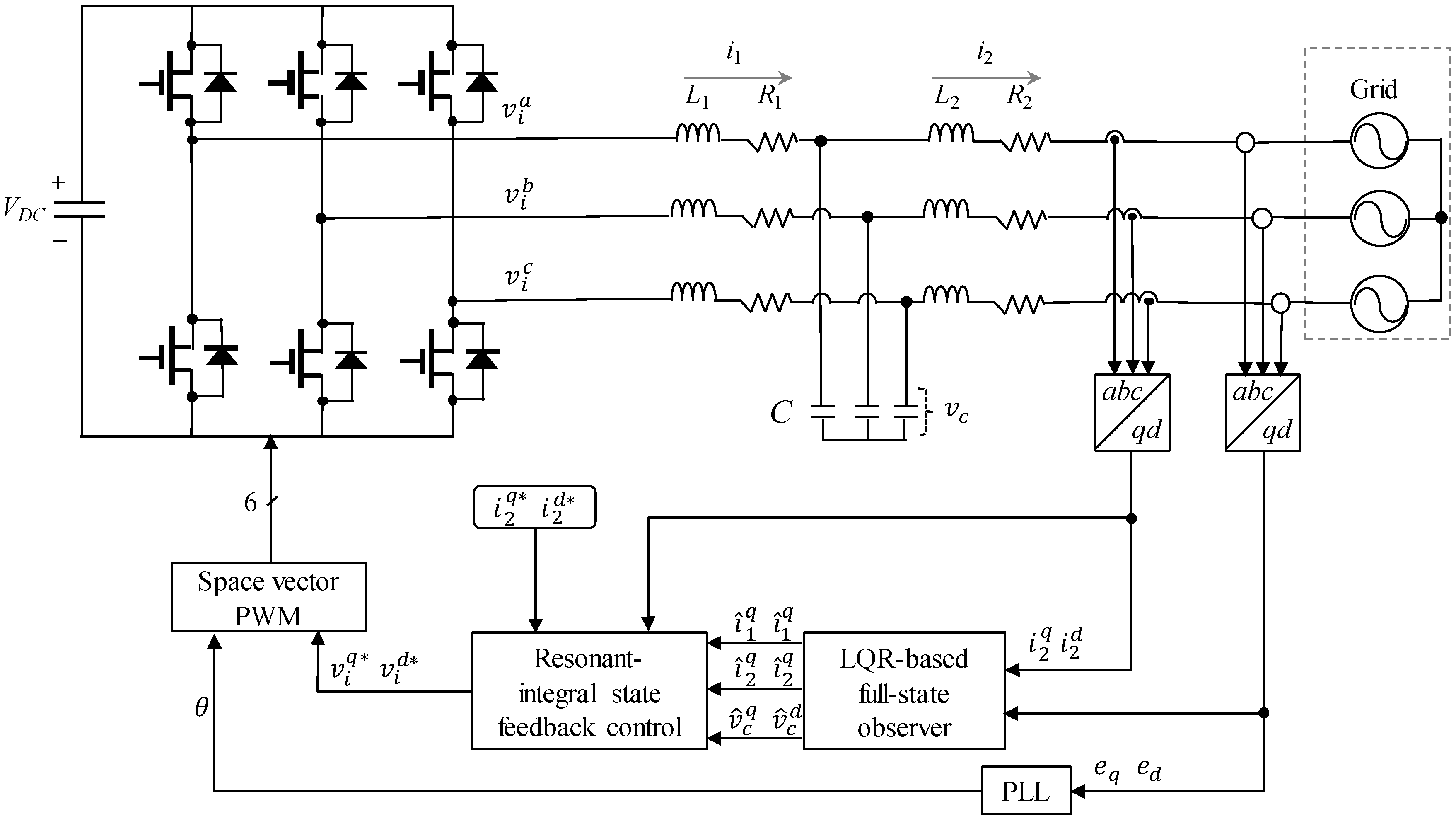
In order to verify the feasibility and validity of the proposed current control scheme, simulations were carried out for an LCL-filtered three-phase grid-connected inverter based on the PSIM software. The configuration of the inverter system and the proposed control scheme are depicted in Figure 2. The system parameters are listed in Table 1.
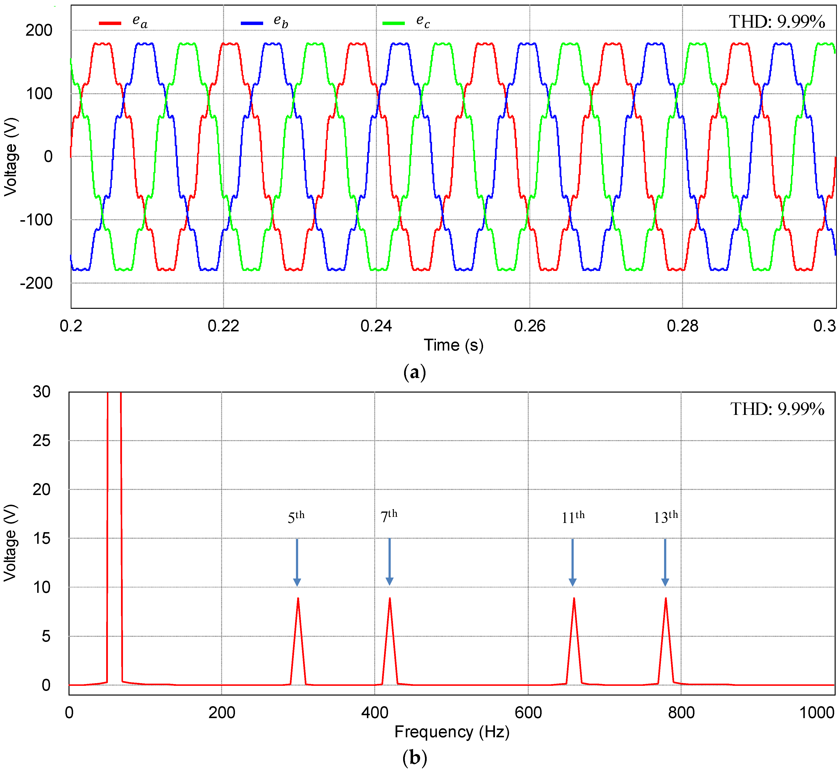
Figure 5 represents three-phase distorted grid voltages used for the simulations. The abnormal grid voltages contain the harmonic components in the order of the 5th, 7th, 11th, and 13th with the magnitude of 5% with respect to the nominal grid voltages, which yields the THD value of 9.99%.
Figure 6 shows the simulation results of the proposed current control scheme at steady-state under the distorted grid condition as in Figure 5. Figure 6a shows the grid-side current responses at the SRF with the reference currents. As can be observed from Figure 6a, the grid-side currents track the reference values well. Figure 6b,c represent the steady-state responses for the inverter-side current and capacitor voltage, respectively.
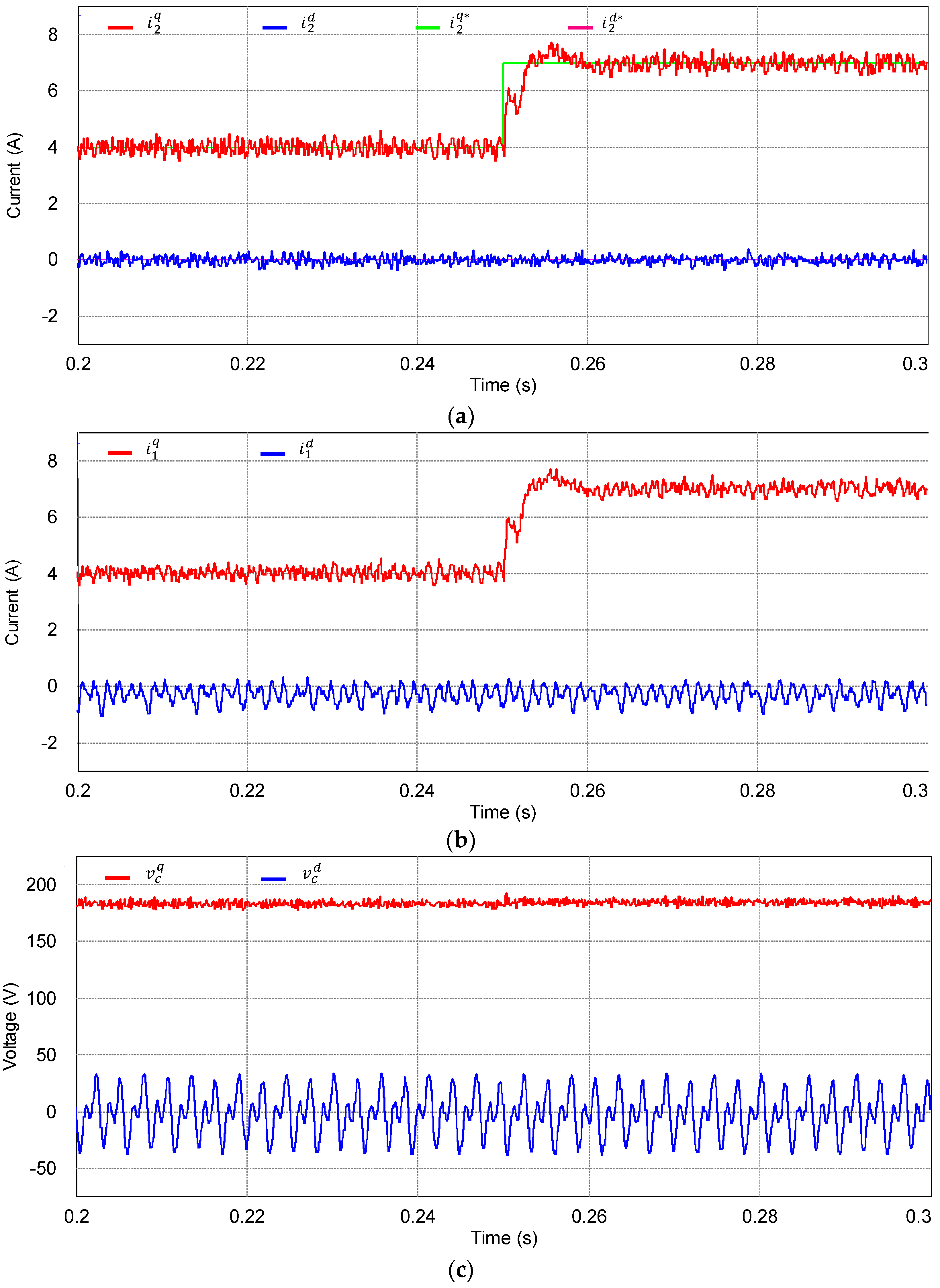
To demonstrate the transient performance of the proposed current control scheme, Figure 7 shows the simulation results under the same distorted grid condition when the q-axis reference current has a step change from 4 to 7 A at 0.25 s. Similarly, Figure 7a through Figure 7c represents the grid-side current responses, inverter-side current responses, and capacitor voltage responses at the SRF, respectively. As is shown in Figure 7a, the grid-side currents reach the reference very rapidly, which indicates a sufficiently fast transient response of the proposed control scheme. In addition, the fast transient performance of the proposed control scheme can be also inferred from Figure 7b,c.
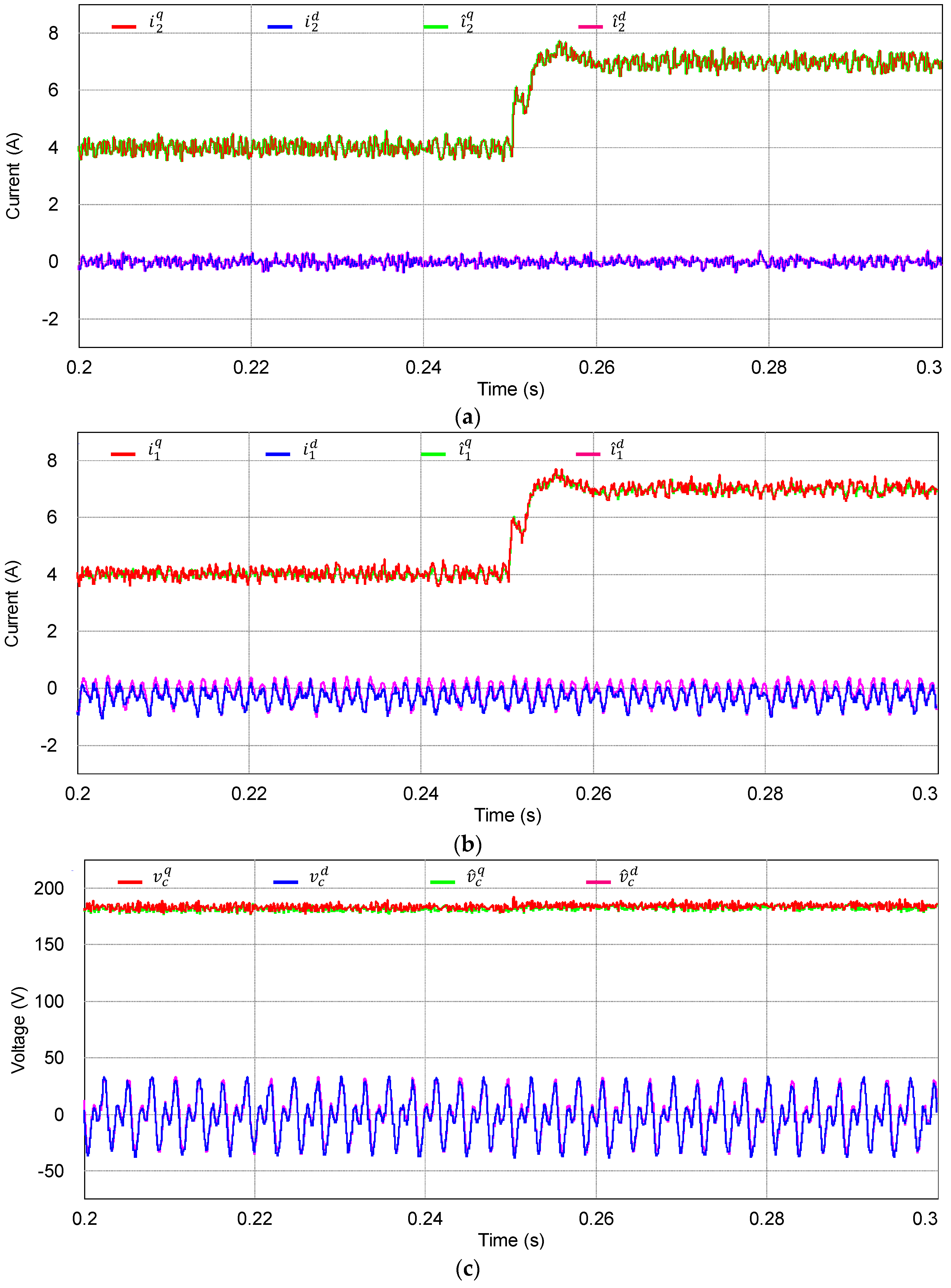
Figure 8 shows the simulation results for the inverter states and estimated states using the proposed integral-resonant state feedback control scheme with the discrete-time current full-state observer at the SRF. The optimal observer gains are obtained by using the MATLAB “dlqr” function with given inverter parameters. As can be clearly observed from Figure 8, the estimated states instantly converge to the actual ones even during oscillating transient periods, which confirms a fast and stable operation of the observer.
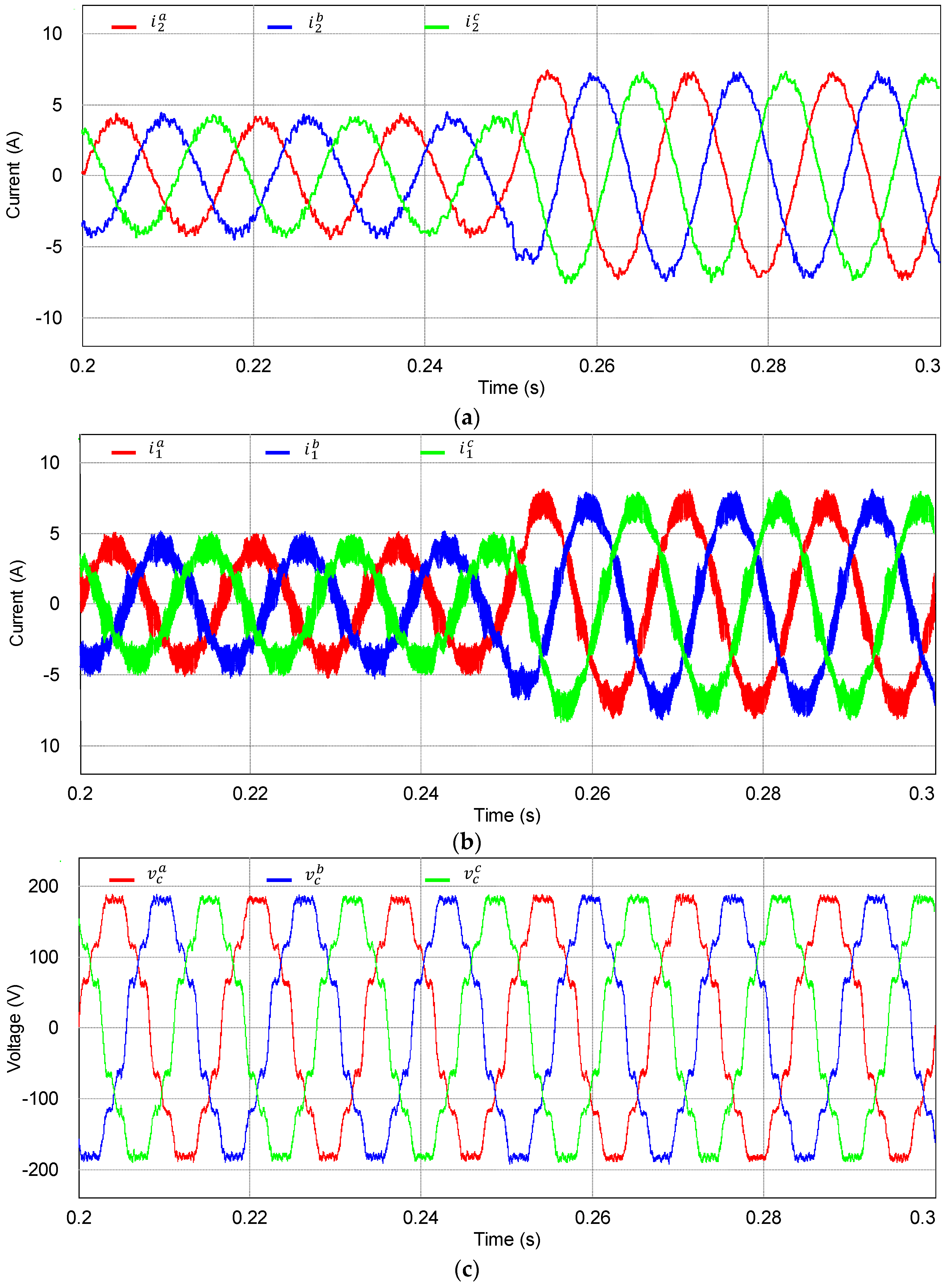
Figure 9 represents the simulation results for measured three-phase variables using the proposed integral-resonant state feedback control scheme with the discrete-time current full-state observer when the q-axis reference current has a step change. As can be seen from Figure 9a, three-phase grid-side current waveforms remain relatively sinusoidal with a desired transient performance. In fact, the grid-side phase currents have the THD level of 3.57% in this case. Also, Figure 9b,c show actual three-phase inverter-side current waveforms and three-phase capacitor voltage waveforms.
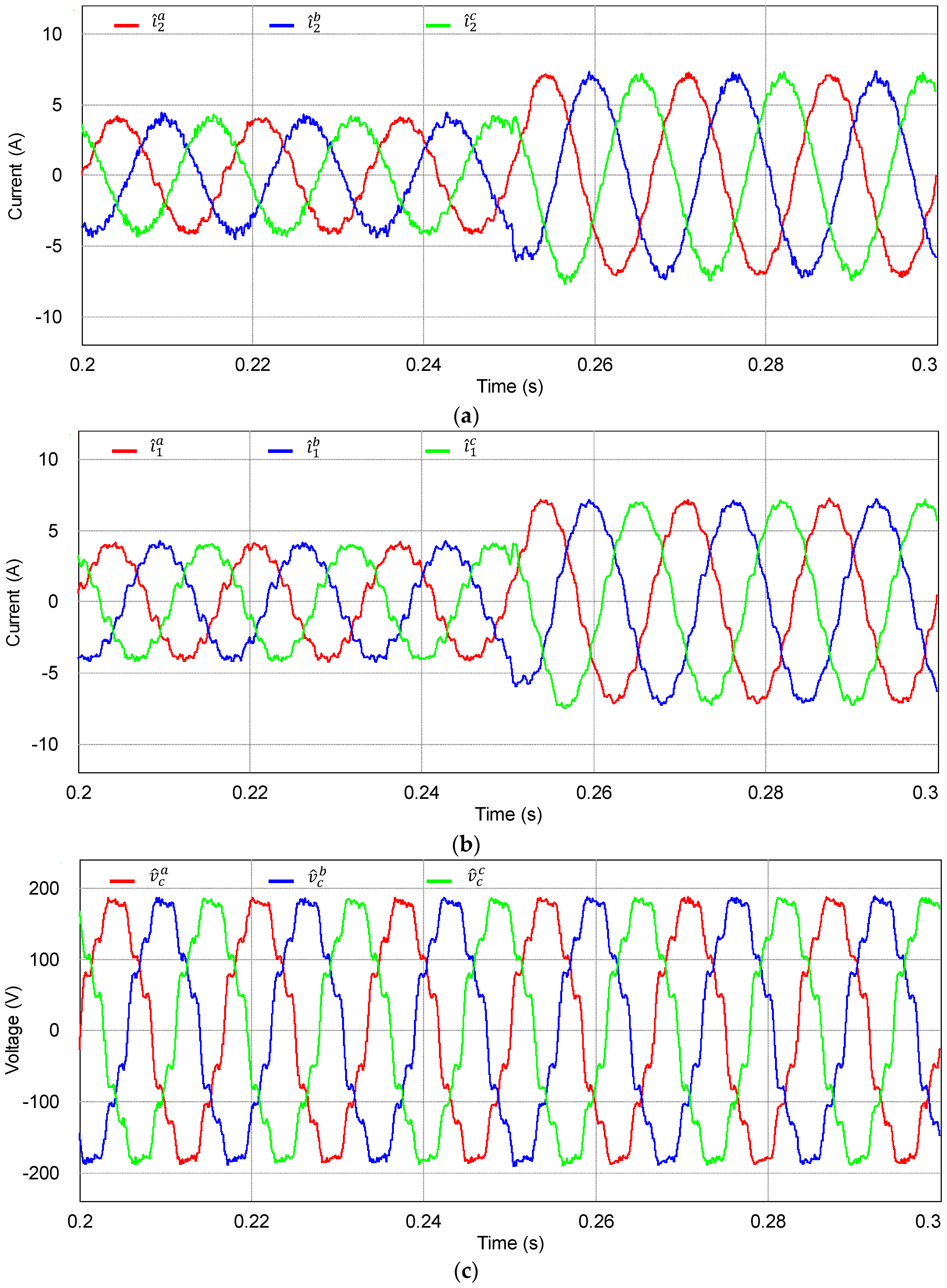
Figure 10 shows the simulation results for the estimated waveforms of three-phase grid-side currents, inverter-side currents, and capacitor voltages under the same condition of Figure 9. In these figures, the estimated three-phase variables are constructed in a DSP by using the estimated states at the SRF to demonstrate the estimating performance of the discrete-time current full-state observer. Obviously, the estimated three-phase variables are compatible with the actual measured three-phase waveforms in Figure 9.
To verify the quality of injected grid currents for the proposed integral-resonant controller under a distorted grid voltage, Figure 11 shows the FFT result for grid-side a-phase current with the harmonic limits specified by the grid interconnection regulation IEEE Std. 1547 [29]. As can be seen clearly, the grid-side phase current yields only small 5th, 7th, 11th, and 13th harmonics components. The resultant THD value is 3.569%, which meets the quality criteria of inverter injected current.
In order to verify the effectiveness of the proposed current control scheme, the performance of the proposed LQR-based current control is compared to PR plus harmonic compensator (PR + HC) structure presented in [3] under the same parameters as proposed in Table 1 and grid voltage condition presented in Figure 5a. The transfer function of a PI + HC controller is given in the stationary frame as:
  G = K P + K r 1 s s 2 + ω 2 + K r 5 s s 2 + ( 5 ω ) 2 + K r 7 s s 2 + ( 7 ω ) 2 + K r 11 s s 2 + ( 11 ω ) 2 + K r 13 s s 2 + ( 13 ω ) 2
where K P is the proportional gain and K r i is the resonant gain with i = 1 ,   5 ,   7 ,   11 ,   13 .
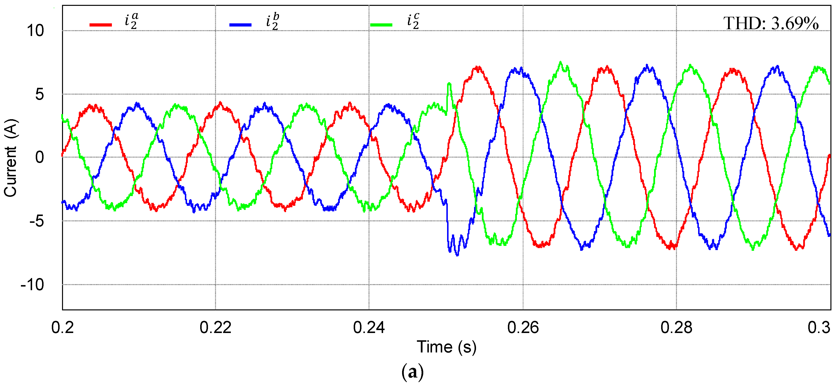
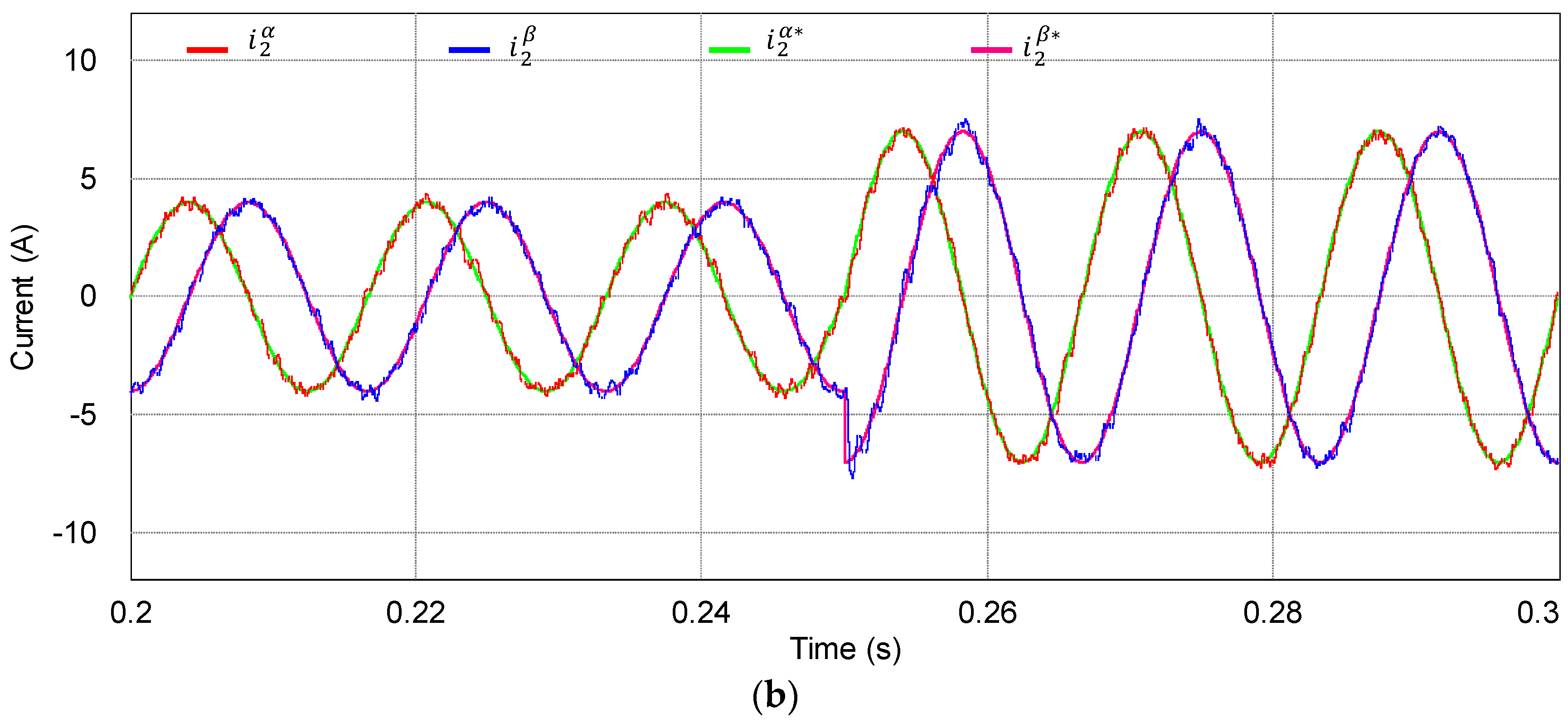
Figure 12 shows the simulation results for the control scheme in [3]. As can be observed from the grid-side current responses in Figure 12a, the PR + HC current control still can compensate effectively the harmonics caused by background voltages. However, the THD value of a-phase current is slightly increased to 3.69% in comparison to that obtained from the LCL filter parameters in [3] because the filter inductor values are reduced. Figure 12b presents the simulation results for the reference tracking performance of grid-side currents in the stationary frame.
In spite of the control performance of the study in [3], it is worth mentioning that the main drawback of the work in [3] lies in the requirement for additional current sensing devices. As obviously shown in the control structure, the method in [3] requires the measurement of currents in inverter-side as well as in grid-side to obtain the capacitor current for active damping. Generally, since additional sensing devices cause complexity in the hardware and a high implementation cost, the purpose of this study is to implement a desired control performance by utilizing only the grid-side current sensors and grid voltage sensors.
Furthermore, the control method in [3] requires 5 resonant controllers including the fundamental component for the α-axis and additional 5 resonant controllers for the β-axis to compensate for the harmonic components in the order of the 5th, 7th, 11th, and 13th. On the contrary, since the proposed scheme is designed in the synchronous reference frame, the total of 4 resonant controllers are sufficient for the q- and d- axes to compensate the 6th and 12th order harmonic components. From the viewpoint of digital implementation burden, the proposed control scheme requires only an acceptable level of computation and complexity.

5. Experimental Results

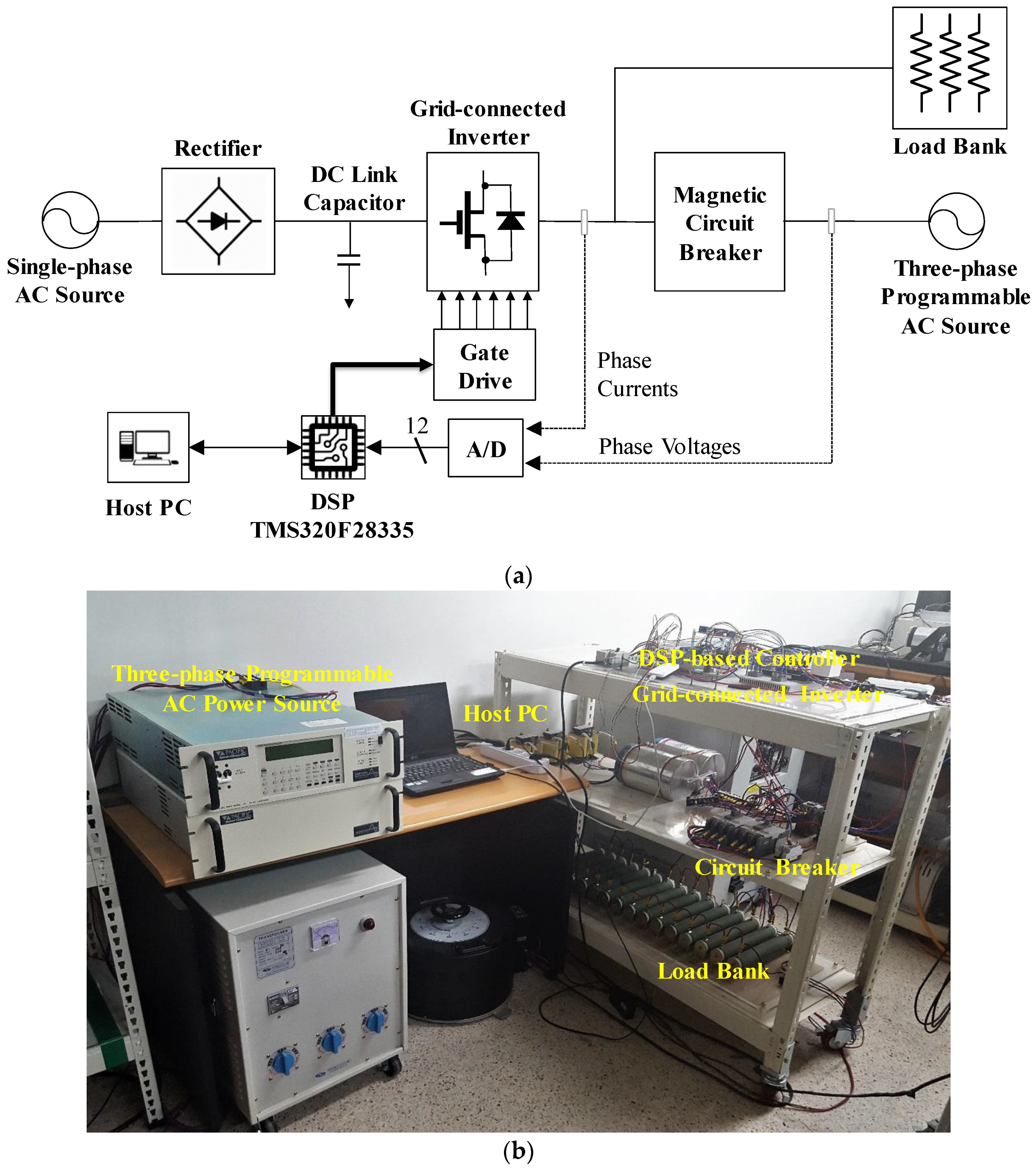
In order to verify the feasibility of the proposed control scheme, the control algorithm is implemented on 32-bit floating-point DSP TMS320F28335 (Texas Instruments, Inc, Dallas, TX, USA) to control a 2 kVA prototype grid-connected inverter [30]. The configuration of the entire system is illustrated in Figure 13a. The sampling period is set to 100 µs, which results in the switching frequency of 10 kHz. Figure 13b depicts the photograph of the experimental test setup. The experimental setup is composed of a three-phase inverter connected to the grid through an LCL filter, a magnetic contactor for grid connecting operations, an AC power source to emulate three-phase grid voltages in the ideal as well as distorted grid conditions, and current and voltage sensors used to measure grid-side currents and grid voltages, respectively.
Figure 14a shows three-phase distorted grid voltages used for the experimental evaluation. Similar to Figure 5 in the simulation, these grid voltages contain the 5th, 7th, 11th, and 13th harmonics with the magnitude of 5% of the fundamental component. Figure 14b presents the FFT results for a-phase grid voltage, which shows each harmonic component similar to Figure 5b.
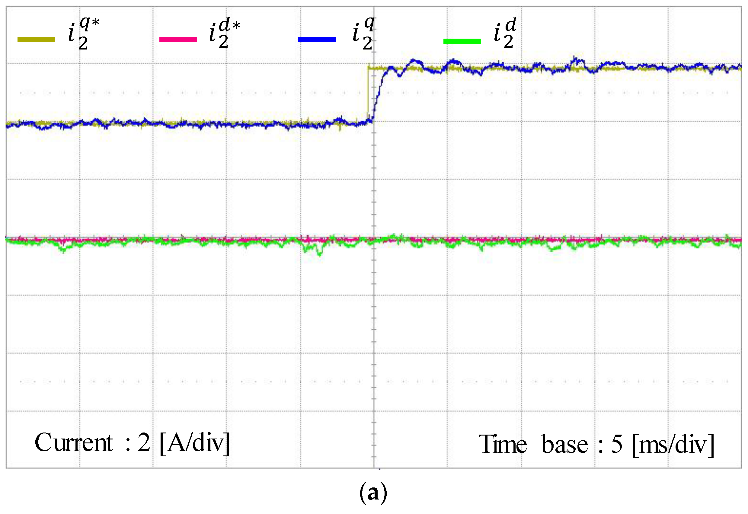
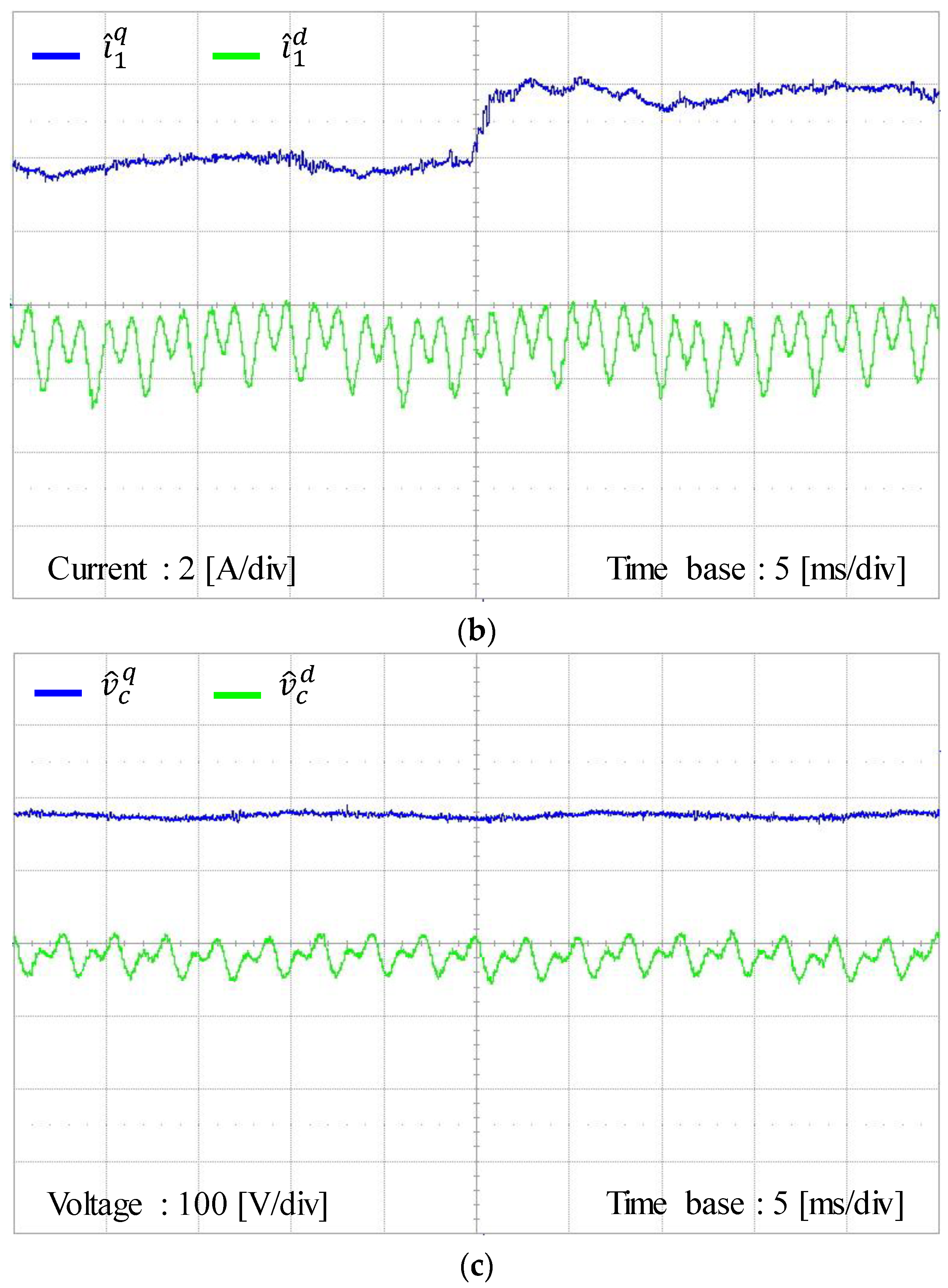
Figure 15 shows the experimental results for the proposed control scheme under the step change in q-axis current reference from 4 to 6 A. It can be observed from Figure 15a that the inverter output currents can track their references well and instantly reach a new steady-state value, which demonstrates a fast transient response of the proposed control scheme. Figure 15b shows three-phase grid-side current responses. It is confirmed from this figure that the proposed control scheme provides considerable sinusoidal grid-side phase currents, which coincides well with the simulation results in Figure 9a, verifying a stable and reliable operation of the inverter system.
Figure 16 presents the experimental results for the estimated grid-side currents, estimated inverter-side currents, and estimated capacitor voltages by using the discrete-time current full-state observer at the SRF under the step change in q-axis current reference. The estimated grid-side currents at the SRF in Figure 16a show similar behavior with actual states in Figure 15a. Also, the experimental estimated waveforms are very similar to the simulation results in Figure 8.
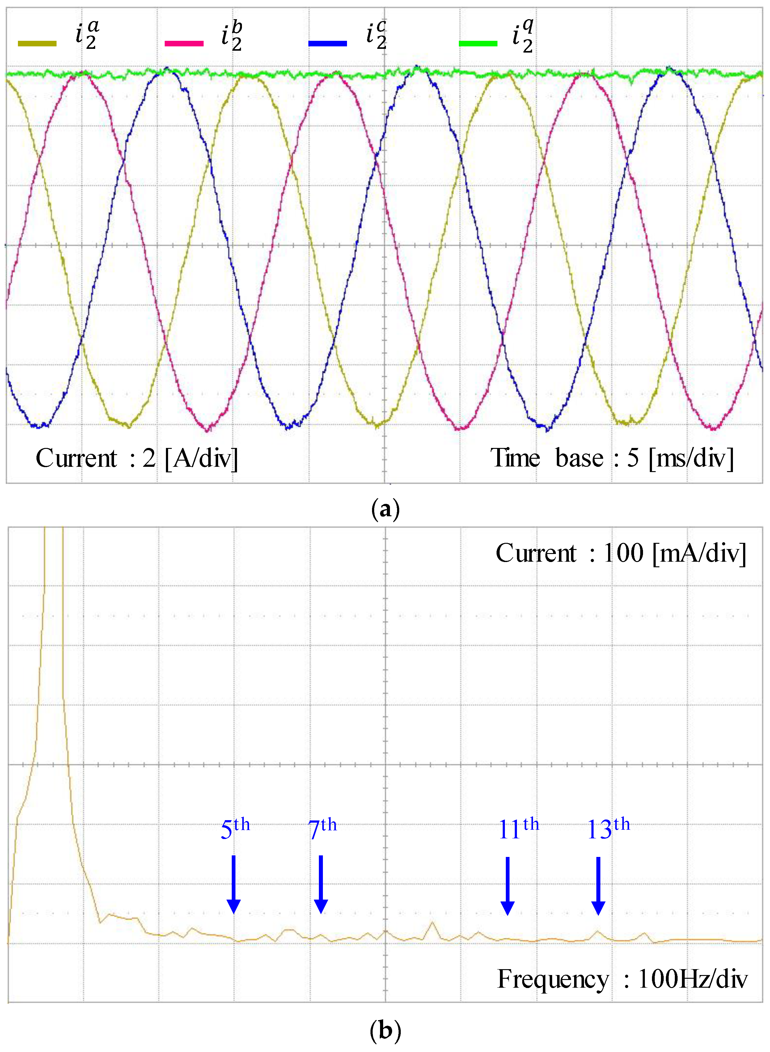
Figure 17a shows the experimental results for three-phase grid-side current waveforms at steady-state with the proposed current control scheme under harmonically distorted grid conditions as in Figure 14. Generally, the harmonic distortion on grid voltages directly influence on the grid-side current control performance, reducing the power quality of distributed generation system. However, the three-phase grid-side current waveform of the proposed scheme shows quite sinusoidal phase currents in spite of such a severe harmonic distortion on grid voltages. As is shown in Figure 17b, the FFT result for a-phase current shows negligibly small harmonic components in output current, which successfully meets the requirements for the harmonic limits specified by IEEE Standard 519-1992.
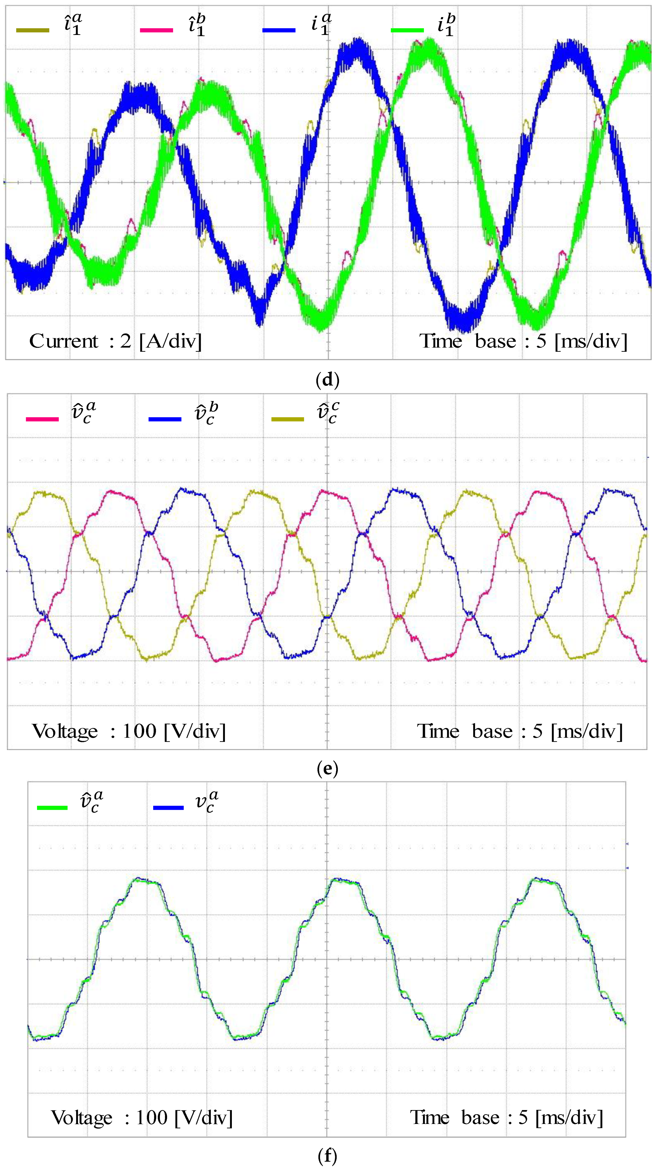
Figure 18 represents the experimental results for the estimating performance of the discrete-time current full-state observer. To evaluate the estimating performance of the observer by comparison, Figure 18a,b show the estimating performance for grid-side three-phase currents and the comparison of these estimated signals with measured grid-side currents. In these figures, the estimated three-phase variables i ^ 2 a , i ^ 2 b , and i ^ 2 c are constructed in a DSP by using the estimated states i ^ 2 q and i ^ 2 d at the SRF. The experimental results are well matched with the simulation results in Figure 10a and validate the stability and reliability of the estimated states by the current full-state observer. Similarly, Figure 18c,d show the estimating performance for inverter-side three-phase currents, and Figure 18e,f for three-phase capacitor voltages, respectively. Also, the estimated three-phase variables i ^ 1 a , i ^ 1 b , and i ^ 1 c are calculated in a DSP from the estimated currents i ^ 1 q and i ^ 1 d at the SRF, and v ^ c a , v ^ c b , and v ^ c c from the estimated capacitor voltages v ^ c q and v ^ c d at the SRF, respectively. It can be confirmed from these figures that all the estimated three-phase variables converge to actual measured three-phase variables well.

6. Conclusions

This paper has presented an LQR-based current control design for an LCL-filtered grid-connected inverter. The proposed control scheme has been constructed by using the IM principle in the SRF to augment integral and resonant terms into a state feedback control. As a result, the control scheme successfully achieves control objectives such as an asymptotic reference tracking and disturbance rejection, which significantly reduces the impact of grid voltage distortion on the output current. Moreover, since the proposed scheme is implemented in the SRF, both the negative and positive sequence harmonics can be effectively compensated for by only one resonant term, which leads to a decrease in the number of regulators. This feature is usually preferred because the required THD performance can be met with further reduction in computation efforts. Furthermore, with the aim of avoiding the increase of sensing devices in an LCL-filtered grid-connected inverter system in comparison with L-filtered counterpart, a current full-state observer in the discrete-time domain has been discussed in detail to estimate all the state variables. On account of the augmentation of the resonant terms as well as the integral term into the inverter model, an increased number of feedback gains should be selected. To deal with such a limitation, an optimal LQR approach is adopted as a way of choosing the feedback gains systematically, in which the discrete cost function is minimized to satisfy the stability and robustness requirements of the system. As a result, both the system feedback and observer gains can be selected based on the LQR method in an effective and straightforward way. In addition to that, the control objectives such as the reference tracking and harmonic compensation capability can be effectively achieved without increasing the required number of sensing devices.
In order to evaluate the feasibility and validity of the proposed control scheme, the whole control algorithm is implemented on 32-bit floating-point DSP TMS320F28335 to control 2 kVA prototype grid-connected inverter. Comprehensive simulation and experimental results are presented under distorted grid voltage conditions to demonstrate the usefulness of the proposed current control scheme.

Author Contributions

T.V.T., S.-J.Y., and K.-H.K. conceived the main concept of the control structure and developed the entire system. T.V.T. and S.-J.Y. carried out the research and analyzed the numerical data with guidance from K.-H.K. T.V.T., S.-J.Y., and K.-H.K. collaborated in the preparation of the manuscript.

Funding

This work was also supported by the Human Resources Development of the Korea Institute of Energy Technology Evaluation and Planning (KETEP), grant funded by the Korea government Ministry of Trade, Industry and Energy (NO. 20174030201840).

Acknowledgments

This research was supported by Basic Science Research Program through the National Research Foundation of Korea (NRF) funded by the Ministry of Education (NRF-2016R1D1A1B03930975).

Conflicts of Interest

The authors declare no conflict of interest.

References

  1. Trinh, Q.N.; Lee, H.H. An advanced current control strategy for three-phase shunt active power filters. IEEE Trans. Indus. Electr. 2013, 60, 5400–5410. [Google Scholar] [CrossRef]
  2. Peña-Alzola, R.; Liserre, M.; Blaabjerg, F.; Sebastián, R.; Dannehl, J.; Fuchs, F. Analysis of the passive damping losses in LCL-filter-based grid converters. IEEE Trans. Power Electr. 2013, 28, 2642–2646. [Google Scholar] [CrossRef]
  3. Jia, Y.; Zhao, J.; Fu, X. Direct grid current control of LCL-filtered grid-connected inverter mitigating grid voltage disturbance. IEEE Trans. Power Electr. 2014, 29, 1532–1541. [Google Scholar]
  4. Han, Y.; Shen, P.; Zhao, X.; Guerrero, J. Control strategies for islanded microgrid using enhanced hierarchical control structure with multiple current-loop damping schemes. IEEE Trans. Smart Grid 2017, 8, 1139–1153. [Google Scholar] [CrossRef]
  5. Jin, W.; Li, Y.; Sun, G.; Bu, L. H∞ repetitive control based on active damping with reduced computation delay for LCL-type grid-connected inverters. Energies 2017, 10, 586. [Google Scholar] [CrossRef]
  6. Bolsens, B.; Brabandere, K.D.; Den Keybus, J.V.; Driesen, J.; Belmans, R. Model-based generation of low distortion currents in grid-coupled PWM-inverters using an LCL output filter. IEEE Trans. Power Electr. 2006, 21, 1032–1040. [Google Scholar] [CrossRef]
  7. Kukkola, J.; Hinkkanen, M. Observer-based state-space current control for a three-phase grid-connected converter equipped with an LCL filter. IEEE Trans. Indus. Appl. 2014, 50, 2700–2709. [Google Scholar] [CrossRef]
  8. Kukkola, J.; Hinkkanen, M.; Zenger, K. Observer-based state-space current controller for a grid converter equipped with an LCL filter: Analytical method for direct discrete-time design. IEEE Trans. Indus. Appl. 2015, 51, 4079–4090. [Google Scholar] [CrossRef]
  9. Zmood, D.N.; Holmes, D.G. Stationary frame current regulation of PWM inverters with zero steady-state error. IEEE Trans. Power Electr. 2003, 18, 814–822. [Google Scholar] [CrossRef]
  10. Lascu, C.; Asiminoaei, L.; Boldea, I.; Blaabjerg, F. High performance current controller for selective harmonic compensation in active power filters. IEEE Trans. Power Electr. 2007, 22, 1826–1835. [Google Scholar] [CrossRef]
  11. Kulka, A.; Undeland, T.; Vazquez, S.; Franquelo, L.G. Stationary frame voltage harmonic controller for standalone power generation. In Proceedings of the European Conference on Power Electronics Applications, Aalborg, Denmark, 2–5 September 2007; pp. 1–10. [Google Scholar]
  12. Gabe, I.J.; Montagner, V.F.; Pinheiro, H.P. Design and implementation of a robust current controller for VSI connected to the grid through an LCL filter. IEEE Trans. Power Electr. 2009, 24, 1444–1452. [Google Scholar] [CrossRef]
  13. Gonzatti, R.B.; Ferreira, S.C.; da Silva, C.H.; Pereira, R.R.; da Silva, L.E.B.; Lambert-Torres, G. Using smart impedance to transform high impedance microgrid in a quasi-infinite busbar. IEEE Trans. Smart Grid 2017, 8, 428–436. [Google Scholar] [CrossRef]
  14. Perez-Estevez, D.; Doval-Gandoy, J.; Yepes, A.G.; Lopez, O.; Baneira, F. Enhanced resonant current controller for grid-connected converters with LCL filter. IEEE Trans. Power Electr. 2017. [Google Scholar] [CrossRef]
  15. Liu, Y.; Wu, W.; He, Y.; Lin, Z.; Blaabjerg, F.; Chung, H.S.H. An efficient and robust hybrid damper for LCL or LLCL-based grid-tied inverter with strong grid-side harmonic voltage effect rejection. IEEE Trans. Indus. Electr. 2016, 63, 926–936. [Google Scholar] [CrossRef]
  16. Liserre, M.; Teodorescu, R.; Blaabjerg, F. Multiple harmonics control for three-phase grid converter systems with the use of PI-RES current controller in a rotating frame. IEEE Trans. Power Electr. 2006, 21, 836–841. [Google Scholar] [CrossRef]
  17. Lai, N.B.; Kim, K.H. Robust control scheme for three-phase grid-connected inverters with LCL-filter under unbalanced and distorted grid conditions. IEEE Trans. Energy Conver. 2018, 33, 506–515. [Google Scholar] [CrossRef]
  18. Bojoi, R.I.; Griva, G.; Bostan, V.; Guerriero, M.; Farina, F.; Profumo, F. Current control strategy for power conditioners using sinusoidal signal integrators in synchronous reference frame. IEEE Trans. Power Electr. 2005, 20, 1402–1412. [Google Scholar] [CrossRef]
  19. Fu, X.; Li, S. A novel neural network vector control for single-phase grid-connected converters with L, LC and LCL filters. Energies. 2017, 9, 328. [Google Scholar] [CrossRef]
  20. Francis, B.; Wonham, W. The internal model principle of control theory. Automatica 1976, 12, 457–465. [Google Scholar] [CrossRef]
  21. Yoon, S.J.; Lai, N.B.; Kim, K.H. A systematic controller design for a grid-connected inverter with LCL filter using a discrete-time integral state feedback control and state observer. MDPI Energies 2018, 11, 1–20. [Google Scholar]
  22. Lim, J.S.; Park, C.; Han, J.; Lee, Y.I. Robust tracking control of a three-phase DC–AC inverter for UPS applications. IEEE Trans. Indus. Electr. 2014, 61, 4142–4151. [Google Scholar] [CrossRef]
  23. Hasanzadeh, A.; Edrington, C.S.; Mokhtari, H. A novel LQR based optimal tuning method for IMP-based linear controllers of power electronics/power systems. In Proceedings of the IEEE Conference on Decision and Control, Orlando, FL, USA, 12–15 December 2011; pp. 7711–7716. [Google Scholar]
  24. Perez-Estevez, D.; Doval-Gandoy, J.; Yepes, A.; Lopez, O. Positive- and negative-sequence current controller with direct discrete-time pole placement for grid-tied converters with LCL filter. IEEE Trans. Power Electr. 2017, 32, 7207–7221. [Google Scholar] [CrossRef]
  25. Franklin, G.; Workman, M.; Powell, J. Digital Control of Dynamic Systems; Ellis-Kagle Press: Half Moon Bay, CA, USA, 2006. [Google Scholar]
  26. Maccari, L.; Massing, J.; Schuch, L.; Rech, C.; Pinheiro, H.; Oliveira, R.; Montagner, V. LMI-based control for grid-connected converters with LCL filters under uncertain parameters. IEEE Trans. Power Electr. 2014, 29, 3776–3785. [Google Scholar] [CrossRef]
  27. Phillips, C.L.; Nagle, H.T. Digital Control System Analysis and Design, 3rd ed.; Prentice Hall: Englewood Cliffs, NJ, USA, 1995. [Google Scholar]
  28. Ogata, K. Discrete Time Control Systems, 2nd ed.; Prentice-Hall: Englewood Cliffs, NJ, USA, 1995. [Google Scholar]
  29. IEEE. IEEE Standard for Interconnecting Distributed Resources with Electric Power Systems; IEEE Std.1547; IEEE: New York, NY, USA, 2003. [Google Scholar]
  30. Texas Instrument. TMS320F28335 Digital Signal Controller (DSC)—Data Manual; Texas Instrument: Dallas, TX, USA, 2008. [Google Scholar]
Figure 1. Configuration of a grid-connected inverter with inductive-capacitive-inductive (LCL) filter.
Energies 11 02062 g001
Figure 2. Block diagram of the proposed integral-resonant state feedback current control scheme with observer.
Energies 11 02062 g002
Figure 3. Detailed control block diagram of the proposed current controller.
Energies 11 02062 g003
Figure 4. State feedback control using current full-state observer in the discrete-time domain.
Energies 11 02062 g004
Figure 5. Distorted grid voltages. (a) Three-phase distorted grid voltages; (b) Fast Fourier transform (FFT) result of a-phase voltage.
Energies 11 02062 g005
Figure 6. Simulation results for steady-state responses under distorted grid voltage with the proposed controller. (a) Grid-side current responses at the synchronous reference frame (SRF); (b) Inverter-side current responses at the SRF; (c) Capacitor voltage responses at the SRF.
Energies 11 02062 g006
Figure 7. Simulation results for transient responses under distorted grid voltage with the proposed controller. (a) Current references and grid-side current responses at the synchronous reference frame (SRF); (b) inverter-side current responses at the SRF; (c) capacitor voltage responses at the SRF.
Energies 11 02062 g007
Figure 8. Simulation results for the proposed control scheme with the discrete-time full-state observer under step change in q-axis current reference; states and estimated states. (a) Waveforms of grid-side currents and estimated states at the SRF; (b) waveforms of inverter-side currents and estimated states at the SRF; (c) waveforms of capacitor voltages and estimated states at the SRF.
Energies 11 02062 g008
Figure 9. Simulation results for measured three-phase variables with the proposed control scheme under step change in q-axis current reference. (a) Three-phase grid-side current waveforms; (b) three-phase inverter-side current waveforms; (c) three-phase capacitor voltage waveforms.
Energies 11 02062 g009
Figure 10. Simulation results for estimated three-phase variables with state observer under step change in q-axis current reference. (a) Estimated three-phase grid-side currents; (b) estimated three-phase inverter-side currents; (c) estimated three-phase capacitor voltages.
Energies 11 02062 g010
Figure 11. FFT result for grid-side a-phase current of the proposed controller under distorted grid voltages.
Energies 11 02062 g011
Figure 12. Simulation results for the proportional-resonant plus harmonic compensator (PR + HC) control scheme under step change. (a) Three-phase grid-side current waveforms; (b) current references and grid-side current responses at the stationary frame.
Energies 11 02062 g012aEnergies 11 02062 g012b
Figure 13. Configuration of the experimental system. (a) Block diagram of the overall system; (b) photograph of the experimental test setup.
Energies 11 02062 g013
Figure 14. Distorted three-phase grid voltages used in the experiments. (a) Three-phase distorted grid voltages; (b) FFT result of a-phase grid voltage.
Energies 11 02062 g014
Figure 15. Experimental results for the proposed control scheme under step change in q-axis current reference. (a) Grid-side current responses at the SRF; (b) three-phase grid-side current responses.
Energies 11 02062 g015aEnergies 11 02062 g015b
Figure 16. Experimental results for the estimated states with the discrete-time full-state observer under step change in q-axis current reference. (a) Responses of estimated grid-side currents at the SRF; (b) responses of estimated inverter-side currents at the SRF; (c) responses of estimated capacitor voltages at the SRF.
Energies 11 02062 g016aEnergies 11 02062 g016b
Figure 17. Experimental results for the proposed control scheme at steady-state. (a) Three-phase grid-side current waveforms; (b) FFT result for a-phase current.
Energies 11 02062 g017
Figure 18. Experimental results for the estimating performance with the discrete-time full-state observer. (a) Estimating performance for grid-side three-phase currents; (b) comparison of the estimated grid-side currents and measured grid-side currents; (c) estimating performance for inverter-side three-phase currents; (d) comparison of the estimated inverter-side currents and measured inverter-side currents; (e) estimating performance for three-phase capacitor voltages; (f) comparison of the estimated capacitor voltage and measured capacitor voltage.
Energies 11 02062 g018aEnergies 11 02062 g018b
Table 1. System parameters of a grid-connected inverter.
ParametersValueUnits
DC-link voltage420V
Resistance (load bank)24 Ω
Filter resistance0.5 Ω
Filter capacitor4.5µF
Inverter-side filter inductance1.7mH
Grid-side filter inductance0.9mH
Grid voltage (line-to line rms)220V
Grid frequency60Hz

