An Improved Energy Management Strategy for Hybrid Energy Storage System in Light Rail Vehicles


National Active Distribution Network Technology Research Center, Beijing Jiaotong University, Beijing 100044, China
*
Author to whom correspondence should be addressed.
Energies 2018, 11(2), 423; https://doi.org/10.3390/en11020423
Submission received: 17 January 2018
/
Revised: 1 February 2018
/
Accepted: 5 February 2018
/
Published: 12 February 2018
(This article belongs to the Section D: Energy Storage and Application)
Abstract
:A single-objective optimization energy management strategy (EMS) for an onboard hybrid energy storage system (HESS) for light rail (LR) vehicles is proposed. The HESS uses batteries and supercapacitors (SCs). The main objective of the proposed optimization is to reduce the battery and SC losses while maintaining the SC state of charge (SOC) within specific limits based on the distance between consecutive LR stations. To do this, a series of optimized SOC limits is used to prevent the SC from becoming exhausted prematurely instead of the standard SC SOC penalty term in the cost function. Meanwhile, a rule-based EMS (RB-EMS) is used to give the SCs charging priority over the batteries when the vehicle is braking. Moreover, a simplified method for the optimization is proposed to reduce the computational burden. Simulation and experimental results for the proposed EMS and a standard SC SOC penalty-based cost function optimization are provided to evaluate losses. As a result, it is shown that the proposed EMS, compared with standard SC SOC penalty-based cost function optimization, decreases losses and prevents the SOC from reach the discharging limits.
1. Introduction
A typical light rail (LR) network has a high volume, a high density of vehicle operation, and a short distance between stations. Most of these LR networks are powered by an overhead catenary system, which has some negative consequences [1]: First, a catenary system visually pollutes a city’s infrastructure. Second, peak power delivery and consumption patterns of the LR vehicle can provoke power supply issues, such as voltage variations. Third, the catenary system has a low energy efficiency due to limited braking energy recovery and high losses. An effective solution to the above issues is the implementation of an energy storage system (ESS) on urban transportation networks for braking energy recovery purposes [2]. Another feasible solution is the direct installation of an ESS on LR vehicles that can meet the requirements of traction applications and serve as power supplies [3,4,5,6]. An onboard ESS for LR vehicles has the following advantages: First, urban transportation areas can be extended to catenary-free zones. Second, energy transmission does not need to go through the catenary, which significantly minimizes transportation systems losses [7]. Third, it allows a flexible and simpler infrastructure. Finally, the energy recovery of an onboard ESS, compared to its competitors, has greater flexibility and lower investment costs [6].
Batteries have been considered the most common energy storage component of an ESS because of their high energy density, compact size, and reliability [8,9,10]. However, they also have well-known disadvantages such as low specific power, poor properties at low temperature, and a short life-cycle. Supercapacitors (SCs) by comparison have much higher power densities and much longer service lives, but lower energy densities [1]. Additionally, the use of SCs as auxiliary ESSs for hybrid energy storage systems (HESSs) has been demonstrated to increase the system’s peak power, reduce internal losses, and assist batteries during peak power demands and regenerative braking. Therefore, such use reduces battery drain, lengthens battery life, and enables the use of smaller battery packs [9,11]. The HESSs combining two or more types of storage components with complementary features have been extensively studied, and HESSs composed of batteries and SCs are one of the most prominent combinations [9,12,13,14,15,16,17,18,19]. In an HESS, SCs are usually used to absorb the high power of regenerative braking and to supply maximum power for acceleration, while batteries are used for vehicle operations that involves less/rated power [20].
Recently, the development of control strategies for energy management systems (EMS) has become a topic of interest for researchers [5,11,12,13,21,22,23,24,25,26,27,28]. The EMS plays an important role to ensure that the onboard ESS can meet energy reduction requirements [24,26]. Meanwhile, it can also optimize objectives by, for example, constraining the magnitude of the battery charge/discharge current to extend its life-cycle, minimizing HESS losses, and maintaining the state-of-charge (SOC) of SCs in a suitable range to make sure that it has enough energy to work.
A thorough survey of the current literature shows that the research works concerning EMS can be classified into two categories. The first category of EMS uses a qualitative rule to split the total required power into two parts, such as a battery and an SC, based on several input parameters, i.e., power demand, maximum battery power, SC SOC and battery SOC, etc. Among these EMSs, the most common method is the rule-based energy management strategy (RB-EMS) [11,21,22,23]. This control method is very easy to implement and deals with the limitations of the battery current reference, the SC power reference, etc. RB-EMS is based on a set of conditions that have been decided previously. However, it still has two main drawbacks: First, the distribution rule based on the input parameters, such as the SC SOC and the battery SOC, is hard to design due to the different power demand conditions that need to be evaluated. Second, the HESS loss calculation is not considered carefully. In this category of EMS, fuzzy logic control [26,27] has been developed for power sharing in HESS. These fuzzy-logic-based control algorithms can make this distribution rule more adaptable to complex power demand conditions based on vague or imprecise information [27]. However, the foundation of the membership function of fuzzy control is still based on experience instead of careful calculation. For the RB-EMS, most of the input parameters of the controller need to be decided without quantitative consideration, which means it is hard to achieve optimal performance. The second category is to formulate the HESS power sharing problem as a convex optimization problem that minimizes the system losses (as a major objective) with a cost function. In [13,24,25,28], optimization algorithms and model predictive control (MPC) are proposed to achieve the goal of reducing system losses, employing loss calculations of current instants or a prediction horizon with discrete models. However, these EMSs also have two main drawbacks: First, prediction horizons are relatively short (less than 3 in these papers). As a result, the optimization horizon needs to be tuned in the simulation for a better performance [28]. Second, a single-objective cost function that minimizes power losses cannot be directly implemented. The main reason is that the energy provided by the SC is cheaper than the battery in terms of losses, so the SC will be discharged to its minimum SOC limit prematurely. To solve this problem, all of the above-mentioned literature employs a multi-objective cost function that not only takes power loss into account but also penalizes deviation from the SC SOC operating point. However, this solution also needs to tune the penalty weights to improve performance, especially based on different power demand profiles. For instance, as described in [28], to further utilize the SC SOC range, parameters in the penalty function need to be tuned. Meanwhile, the multi-objective cost function causes the energy distribution result to deviate from the original single objective, minimizing power loss, which is a drawback.
The aim of this work is to propose an EMS based on a single-objective optimization strategy that minimizes the total losses of the battery and the SC. Meanwhile, a variable-length prediction horizon based on a sliding forward window strategy is proposed to extend the optimization horizon to cover the entire LR traction process. Moreover, the penalty term based on the deviation from the SC SOC operating point is replaced with an SC SOC limit based on the distance between consecutive LR stations. An RB-EMS is used to preferentially charge the SC. As a result, a sufficiently long prediction horizon optimization based on the HESS losses is achieved in each entire LR traction power profile. Lastly, simulation and experimental results are provided to evaluate the proposed EMS in terms of loss and SC SOC limit objectives. The performance is also compared with a standard SC SOC penalty-based cost function optimization.
2. Onboard HESS Configurations Analysis
Various topologies for HESSs combining batteries and SCs have been proposed [29,30,31]. In general, onboard ESSs consist of a DC main ESS and one or more DC/DC converters. With such configuration, the use of DC/DC converters is essential for controlling power flow at different voltage levels. In Figure 1a,b, the SC bank and battery bank are connected in parallel with, and through, a DC/DC converter or directly to the DC bus [29]. This configuration is the simplest battery/SC HESS combination, but the power distribution between the batteries and the SCs is uncontrolled. In addition, the conclusions of [30] indicate that a battery–SC hybrid power source can supply a pulsed load with higher peak power, but due to the limitation of the battery bank voltage to the SC bank, the current supplied by the SC bank drops very quickly. Ultimately, the battery–SC hybrid power only shows the battery characteristics, which cannot reflect the power characteristics of the SC bank.
A widely used configuration of hybrid HESS in HEVs is shown in Figure 1c [31]. The DC/DC converter allows the SC to be used on its wide voltage range and the battery bank is directly connected to the DC bus, while maintaining a relatively constant dc-link voltage. But the power of the DC/DC converter must match the large and intermittent SC power, while the battery is forced to suffer from a high frequency current. In Figure 1d, the positions of the battery bank and SC bank are reversed with respect to Figure 1c. In this way, the DC/DC converter can be smaller and the battery current can be controlled, but the DC bus voltage will fluctuate in a wide range because of the uncontrolled working voltage range of the SC. Finally, in Figure 1e, there are two DC/DC converters for the battery bank and the SC bank, respectively. In this configuration, all main electrical variables, i.e., the battery current, the SC current, and the DC bus voltage can be controlled. The main disadvantage is that two converters are required, which increases size and cost. To control the flexibility of both energy storage components and the DC bus voltage stability, this topology is used in this work.
3. Energy Management Strategy Design
3.1. Description
This work proposes a single-objective optimization EMS to minimize the battery and SC losses. The main ideal is to formulate a cost function based on a variable-length prediction horizon to optimize the power sharing problem between consecutive LR stations. Meanwhile, the SOC limitations of SC are obtained due to the prediction horizon. In this way, a series of SOC limitations based on optimizations in each traction/brake stage, instead of the penalty term in the cost function, is used to prevent the SC from becoming exhausted prematurely.
3.2. Proposed Sliding Forward Window Strategy in Traction Stage
Basically, the entire power demand profile of an LR route from the first to the last station consists of a series of inter-station power demand stages. Each stage has two parts: a traction stage and a braking stage. In the traction stage, the energy is provided by an HESS to meet the needs of the LR acceleration operation and is then transferred back to the HESS in the braking stage to improve the efficiency. As described in [26], the power demand profile of an LR route, unlike that of electric vehicles, is known at the beginning of the journey, which makes the future power demand known at each instant k in the prediction horizon. Based on this, a sliding forward window strategy in an LR traction stage is proposed.
As shown in Figure 2, an LR traction stage is divided into a series of steps. The variable-length prediction horizons will extend to the end of this traction stage in each step. For instance, the prediction horizon is at step i, and it is changed to at step j. In this way, the sliding forward window will move as the prediction step increases to always cover the entire traction stage. The proposed EMS considers not only a few steps in the future but also the entire LR traction stage horizon to minimize battery and SC losses, so that it can avoid falling into the zone that deviates from the optimal point, such as when the SC is exhausted prematurely and the batteries then have to supply the power demand alone, which increases the total loss.
3.3. Proposed EMS in the Braking Stage
In order to minimize the battery and SC losses, the SC should be used as much as possible during the traction stages. To achieve this, it is reasonable to give SC charging priority over the battery in the braking stages. As shown in Equation (1), an RB-EMS is used in braking stages to split the power to charge both the battery and the SC.
where and represent the charging power of the SC and the battery, respectively. The refers to the power demand of the LR in the braking stage, is the maximum power of the DC-DC converter, and and are the maximum SOC of the battery and the SC, respectively.
3.4. SC Constraints in Each Traction Stage
A practical LR system in Zhuhai, China, is used to show how the proposed EMS works. The LR power demand and speed profile in the first three stops are shown in Figure 3. The speed curve is considered as a starting point for the design of the LR system by the manufacturer, and the power curve is calculated based on the speed curve and the parameters of the LR. For the auxiliary power load, an average value of 55 kW is considered during the entire line.
The power demand profile in Figure 3 is divided into nine stages alternately: three traction stages, three braking stages, and three stop stages. In each traction stage, the proposed EMS splits the power demand of the battery and the SC by formulating a cost function that minimizes their losses. Since each LR traction stage prediction horizon formulation is used and the SC costs less than batteries in term of losses, the minimum SOC limitation of the SC is probably the end SOC of the SC in each traction stage. Therefore, each traction stage of the SC has a minimum SOC constraint at the end so that the SC is not over-discharged too early, which has the same effect as penalizing the deviation from the SC SOC operating point reference into the cost function. When the LR is braking, the proposed RB-EMS, which gives charging priority to the SC, is used, and the SC will be charged if there is a charger in the substations.
3.5. Battery Model and Super Capacitor Model
For this case, a Toshiba 8.5 Ah Lithium titanate battery was chosen. This battery has better power specifications [32] and a wider operating temperature range compared with other batteries of the same type and is more suitable for applying to LR vehicles [33]. A Thevenin battery model was used for the battery, and the model parameters were obtained by identification techniques, as described in [34]. Figure 4a shows the battery circuit model, where is the battery open-circuit voltage (OCV) and is the battery internal resistance. The parameters and model the transient voltage response of the battery, and represents their voltage. These parameters , , , and are all variables based on different battery SOCs as shown in Figure 5. The term represents the battery output current. The power loss of the battery at any time k can be expressed as
3.6. The Proposed Cost Function and Constraints
In each traction stage, the cost function that minimizes the HESS losses based on Equation (2) and Equation (3) is written as follows:
where and represent the total loss energy of the HESS in a traction stage and the power of loss at instant , respectively, and refer to the power demand of the LR vehicle and the power mix to split the power demand between the battery and the SC at instant k, respectively, and and are the power of loss from the battery and the SC at instant k, respectively. Thus, the prediction of the SC and the battery voltage in based on the models can be obtained as
Based on Equations (4) and (5), the total loss of HESS in a traction stage can be expressed via
where , , , and are the SOC limits of the battery and the SC, respectively. is the maximum current rate of the battery. The cost function, Equation (6), is minimized by using MATLAB’s fmincon function [28], mainly with the SC SOC constraint as a final point, 25%, where an SC releases 75% of its stored energy [25]. Meanwhile, initialization strategies can be used to speed up the optimization computation as described in [35]. According to the total time of one traction stage, as shown in Figure 3, here the is set to be 2 s. Considering that the DC-DC converter loss calculation is always a kind of approximate calculation [28] and that this study is intended to simulate the power flow between the battery and the SC, the DC-DC converters’ losses are considered constant. Only the losses of the energy storage components (the battery and the SC) are considered in this work.
3.7. Simplified Prediction Horizon and Minimization
It is well known that long horizon predictions increase computational burden. However, a moving block technique, where the prediction horizon, n, is divided into two parts , and a larger sampling period for the second horizon achieving to obtain less computational complexity has been adopted in [36]. Following this method, here a variable-horizon can be used to decrease the computational burden with a relatively inaccurate minimum loss based on a larger sampling period in . The above simplified solution can reduce the prediction horizon but relatively increase the loss of the HESS. The performance of this solution will be discussed in the following section.
4. Simulation Results
To demonstrate the performance of the proposed EMS, simulations were performed in MATLAB/Simulink. The first three stops of the power demand profile are shown in Figure 3b. Considering that the total route has 20 stops and the total energy demand is 60 kWh, here the sizing of the battery is set at 78 kWh to provide additional energy to overcome the capacity decline. The SC sizing is set at 5.3 kWh to help the battery to supply the maximum power demand point. Based on the total sizing of the battery and SC and the voltage level of the HESS (approximate 500 V), the numbers of series and parallel are obtained. The battery and SC sizing parameters are shown in Table 1 and Table 2 respectively. The power mix is optimized at every 2 s.
The results with two different cost functions are shown in Figure 6 and Figure 7. As shown in Figure 6b, the SC reaches its minimum SOC limit, 240 V, when the train does not finish the last two traction stages with one-step predictive horizon single-objective optimization EMS. The battery then has to supply the power demand alone from to s and from to s, which is not ideal.
In Figure 7, the MPC-based cost function has two terms: minimizing the loss and penalization for SC SOC. The penalization term is defined as follows [28]:
where is the selected SC SOC midpoint, is the SOC limit of the SC, and is the SC output current. It can be seen that the SC works during all traction stages due to the penalization term, unlike in the one-step predictive horizon single-objective optimization EMS. The total loss of the battery and the SC with the one-step predictive horizon optimization EMS and the SC SOC penalty MPC-based optimization EMS are 0.617 kWh and 0.623 kWh, respectively.
In Figure 8 the proposed sliding forward window optimization EMS allows the SC SOC to reach the minimum SOC limit, 240 V, at the end of the last two traction stages when s and s. The total loss of the battery and the SC with the proposed EMS is 0.541 kWh. The simulation results show that the proposed energy management strategy has a lower loss compared with the MPC-based two objectives cost function optimization.
Figure 9 shows the simplified method as described in Section 3.7. In Figure 9c, the prediction interval is changed in each traction stage. For instance, in Areas, A, B, and C, the power mix is optimized every 2 s, every 4 s, and only once, respectively, in each area. The total loss of the battery and the SC with the variable predictive horizon optimization EMS is 0.549 kWh, but it is only 1.5% higher than the loss with the proposed sliding forward window optimization EMS.
5. Experimental Results
This section presents an experimental verification of the proposed EMS. Three buck/boost bidirectional converter circuits were built using IRF650B MOSFETs, an IFR18650P-1100mAh LiFePO4 battery pack, and a ZNP-2R7-V-107SS2245 SC pack as input sources and a DC bus in parallel as outputs. The first converter was controlled as a reduced power source to simulate the train power requirements. The input current reference was set as
where is the power demand of the LR, is the reduced ratio of the power demand profile in Figure 3b, and stands for the input battery pack voltage of the first converter.
The other two converters are controlled under DC bus voltage control and input current control, respectively, to simulate the HESS. The second converter, with another LiFePO4 battery pack as an input source, controls the DC BUS voltage with an outer voltage PI controller and an inner current PI controller. The third converter employs the SC pack to control the SC current. The input SC current reference is set as
where is the power mix. As described in [26], the power mix can be obtained by interpolating the LR traveled distance (using look-up-tables), but here it is obtained with a time counter in the controller using a look-up-table, which was obtained in simulation. The controller was implemented on a dSPACE DS1005 and a Slave DSP PWM Generation to generate three 20 kHz symmetrical PWMs. The experimental platform parameters are shown in Table 3 and the setup is shown in Figure 10.
As shown in Figure 11, the SC voltage reaches its limit of 6 V when 272 s; the battery then has to supply the power demand alone from to s. Thus, the battery current reaches 1.6 A. In Figure 12, with the two-objectives MPC-based cost function (minimizing the loss and penalization for SC SOC), the SC works during the power demand, which is a positive outcome. However, without an SC SOC limit, the SC voltage reaches 6.5 V and 4.5 V when the LR finishes its last two traction stages. Considering that the battery and SC losses cannot be measured in real systems, here the losses are calculated in the simulation with these experimental parameters. The total loss of the battery and SC with the one-step predictive horizon optimization EMS and the SC SOC penalty-based optimization EMS are 22.36 W and 22.89 W.
In Figure 13, the proposed sliding forward window optimization EMS allows the SC SOC to reach 6.0 V and 5.8 V in the end of the last two traction stages when s and s. The last SC voltage is lower than 6.0 V because the inductor resistance is not considered in the optimization. The total loss of the battery and the SC with the proposed EMS is 21.28 W. The experimental results show that the proposed energy management strategy has a lower loss compared with the penalty-based cost function optimization, as also shown in the simulation results.
6. Conclusions
An onboard ESS as a power supply for LR vehicles can render urban transportation areas catenary-free zones and minimize the effect of catenary systems losses. To combine high energy density with high power density, an HESS with a battery and an SC is proposed in this paper. Different energy management strategies have been compared in other studies, and it has been shown that a multi-objective cost function that considers both the power loss and the deviation from an SC SOC operating point needs to tune the penalty weights. The energy distribution result deviates from the original single objective, minimizing the power loss, which is a drawback. To solve this problem, this paper proposes a single-objective optimization EMS for an onboard HESS for light rail vehicles. The main objective is to reduce battery and SC losses, while the SC SOC within specifics limits based on a sliding forward window is maintained in each traction stage, and to charge the SC as much as possible based on an RB-EMS at each braking stage. A series of SOC limits based on the optimization at each traction stage, instead of the penalty term in the cost function, is used here to prevent the SC from becoming exhausted prematurely. Moreover, a simplified method for this optimization is proposed to reduce computational complexity. Simulation and experimental results are used to verify that the proposed EMS has a 7.5% lower loss compared with the standard SC SOC penalty-based cost function optimization and that the SC SOC always reaches its limitation by the end of each traction stage.
Acknowledgments
This work was supported by the National Key R&D Program of China (Grant Number 2017YFB1201005).
Author Contributions
Long Cheng and Wei Wang proposed the research topic and basic idea; Shaoyuan Wei conceived and designed the experiments; Long Cheng drafted the manuscript; Hongtao Lin and Zhidong Jia performed the experiments. All authors contributed to the writing of the manuscript, and have read and approved the final manuscript.
Conflicts of Interest
The authors declare no conflict of interest.
References
- Lhomme, W.; Delarue, P.; Barrade, P.; Bouscayrol, A. Design and Control of a supercapacitor storage system for traction applications. In Proceedings of the Industry Applications Conference, Kowloon, Hong Kong, China, 2–6 October 2005; pp. 2013–2020. [Google Scholar]
- Barrero, R.; Van Mierlo, J.; Tackoen, X. Energy savings in public transport. IEEE Veh. Technol. Mag. 2008, 3, 26–36. [Google Scholar] [CrossRef]
- Mir, L.; Etxeberria-Otadui, I.; Arenaza, I.P.D.; Sarasola, I.; Nieva, T. A supercapacitor based light rail vehicle: System design and operations modes. In Proceedings of the 2009 IEEE Energy Conversion Congress and Exposition, San Jose, CA, USA, 20–24 September 2009; pp. 1632–1639. [Google Scholar]
- Garcia, P.; Fernandez, L.M.; Garcia, C.A.; Jurado, F. Energy management system of fuel-cell-battery hybrid tramway. IEEE Trans. Ind. Electron. 2010, 57, 4013–4023. [Google Scholar] [CrossRef]
- Torreglosa, J.P.; Garcia, P.; Fernandez, L.M.; Jurado, F. Predictive control for the energy management of a fuel-cell–battery–supercapacitor tramway. IEEE Trans. Ind. Inform. 2013, 10, 276–285. [Google Scholar] [CrossRef]
- Arboleya, P.; Bidaguren, P.; Armendariz, U. Energy is on board: Energy storage and other alternatives in modern light railways. IEEE Electrif. Mag. 2016, 4, 30–41. [Google Scholar] [CrossRef]
- Cheng, L.; Acuna, P.; Wei, S.; Fletcher, J.; Wang, W.; Jiang, J. Fast-Swap Charging: An Improved Operation Mode For Catenary-Free Light Rail Networks. IEEE Trans. Veh. Technol. 2017. [Google Scholar] [CrossRef]
- Tie, S.F.; Tan, C.W. A review of energy sources and energy management system in electric vehicles. Renew. Sustain. Energy Rev. 2013, 20, 82–102. [Google Scholar] [CrossRef]
- Khaligh, A.; Li, Z. Battery, ultracapacitor, fuel cell, and hybrid energy storage systems for electric, hybrid electric, fuel cell, and plug-in hybrid electric vehicles: State of the art. IEEE Trans. Veh. Technol. 2010, 59, 2806–2814. [Google Scholar] [CrossRef]
- Hossain, E.; Perez, R.; Bayindir, R. Implementation of hybrid energy storage systems to compensate microgrid instability in the presence of constant power loads. In Proceedings of the IEEE International Conference on Renewable Energy Research and Applications, San Diego, CA, USA, 5–8 November 2017; pp. 1068–1073. [Google Scholar]
- Herrera, V.I.; Gaztañaga, H.; Milo, A.; Saez-De-Ibarra, A.; Etxeberria-Otadui, I.; Nieva, T. Optimal energy management and sizing of a battery–supercapacitor-based light rail vehicle with a multiobjective approach. IEEE Trans. Ind. Appl. 2016, 52, 3367–3377. [Google Scholar] [CrossRef]
- Amin; Bambang, R.T.; Rohman, A.S.; Dronkers, C.J. Energy management of fuel cell/battery/ supercapacitor hybrid power sources using model predictive control. IEEE Trans. Ind. Inform. 2014, 10, 1992–2002. [Google Scholar]
- Zhao, C.; Yin, H.; Yang, Z.; Ma, C. Equivalent series resistance-based energy loss analysis of a battery semiactive hybrid energy storage system. IEEE Trans. Energy Convers. 2015, 30, 1081–1091. [Google Scholar] [CrossRef]
- Tani, A.; Camara, M.B.; Dakyo, B. Energy management based on frequency approach for hybrid electric vehicle applications: Fuel-cell/lithium-battery and ultracapacitors. IEEE Trans. Veh. Technol. 2012, 61, 3375–3386. [Google Scholar] [CrossRef]
- Lu, S.; Corzine, K.A.; Ferdowsi, M. A new battery/ultracapacitor energy storage system design and its motor drive integration for hybrid electric vehicles. IEEE Trans. Veh. Technol. 2007, 56, 1516–1523. [Google Scholar] [CrossRef]
- Amjadi, Z.; Williamson, S.S. Modeling, simulation, and control of an advanced luo converter for plug-in hybrid electric vehicle energy-storage system. IEEE Trans. Veh. Technol. 2011, 60, 64–75. [Google Scholar] [CrossRef]
- Wang, L.; Collins, E.G.; Li, H. Optimal design and real-time control for energy management in electric vehicles. IEEE Trans. Veh. Technol. 2011, 60, 1419–1429. [Google Scholar] [CrossRef]
- Qu, X.; Wang, Q.; Yu, Y.B. Power demand analysis and performance estimation for active-combination energy storage system used in hybrid electric vehicles. IEEE Trans. Veh. Technol. 2014, 63, 3128–3136. [Google Scholar]
- Saenger, P.; Devillers, N.; Deschinkel, K.; Pera, M.C.; Couturier, R.; Gustin, F. Optimization of electrical energy storage system sizing for an accurate energy management in an aircraft. IEEE Trans. Veh. Technol. 2017, 66, 5572–5583. [Google Scholar] [CrossRef]
- Xiang, C.; Wang, Y.; Hu, S.; Wang, W. A new topology and control strategy for a hybrid battery-ultracapacitor energy storage system. Energies 2014, 7, 2874–2896. [Google Scholar] [CrossRef]
- Carter, R.; Cruden, A.; Hall, P.J. Optimizing for efficiency or battery life in a battery/supercapacitor electric vehicle. IEEE Trans. Veh. Technol. 2012, 61, 1526–1533. [Google Scholar] [CrossRef]
- Song, Z.; Hofmann, H.; Li, J.; Hou, J.; Han, X.; Ouyang, M. Energy management strategies comparison for electric vehicles with hybrid energy storage system. Appl. Energy 2014, 134, 321–331. [Google Scholar] [CrossRef]
- Trovao, J.P.; Pereirinha, P.G.; Jorge, H.M.; Antunes, C.H. A multi-level energy management system for multi-source electric vehicles—An integrated rule-based meta-heuristic approach. Appl. Energy 2013, 105, 304–318. [Google Scholar] [CrossRef]
- Choi, M.E.; Lee, J.S.; Seo, S.W. Real-time optimization for power management systems of a battery/ supercapacitor hybrid energy storage system in electric vehicles. IEEE Trans. Veh. Technol. 2014, 63, 3600–3611. [Google Scholar] [CrossRef]
- Greenwell, W.; Vahidi, A. Predictive control of voltage and current in a fuel cell–ultracapacitor hybrid. IEEE Trans. Ind. Electron. 2010, 57, 1954–1963. [Google Scholar] [CrossRef]
- Herrera, V.; Milo, A.; Gaztañaga, H.; Etxeberria-Otadui, I.; Villarreal, I.; Camblong, H. Adaptive energy management strategy and optimal sizing applied on a battery-supercapacitor based tramway. Appl. Energy 2016, 169, 831–845. [Google Scholar] [CrossRef]
- Li, Q.; Chen, W.; Liu, Z.; Li, M.; Ma, L. Development of energy management system based on a power sharing strategy for a fuel cell-battery-supercapacitor hybrid tramway. J. Power Sources 2015, 279, 267–280. [Google Scholar] [CrossRef]
- Laldin, O.; Moshirvaziri, M.; Trescases, O. Predictive algorithm for optimizing power flow in hybrid ultracapacitor/battery storage systems for light electric vehicles. IEEE Trans. Power Electron. 2013, 28, 3882–3895. [Google Scholar] [CrossRef]
- Pay, S.; Baghzouz, Y. Effectiveness of battery-supercapacitor combination in electric vehicles. In Proceedings of the Power Tech Conference, Bologna, Italy, 13–17 July 2003. [Google Scholar]
- Dougal, R.A.; Liu, S.; White, R.E. Power and life extension of battery-ultracapacitor hybrids. IEEE Trans. Compon. Packag. Technol. 2002, 25, 120–131. [Google Scholar] [CrossRef]
- Camara, M.B.; Gualous, H.; Gustin, F.; Berthon, A. Design and new control of dc/dc converters to share energy between supercapacitors and batteries in hybrid vehicles. IEEE Trans. Veh. Technol. 2008, 57, 2721–2735. [Google Scholar] [CrossRef]
- Wen, Y.L.; Aziz, M.J.A.; Idris, N.R.N. Modelling of lithium-titanate battery with ambient temperature effect for charger design. IET Power Electron. 2016, 9, 1204–1212. [Google Scholar]
- Liu, S.; Jiang, J.; Shi, W.; Ma, Z.; Guo, H. State of charge and peak power estimation of NCM/Li4Ti5O12 battery using ic curve for rail tractor application. In Proceedings of the 2014 IEEE Conference and Expo Transportation Electrification Asia-Pacific (ITEC Asia-Pacific), Beijing, China, 31 August–3 September 2014. [Google Scholar]
- Liu, S.; Jiang, J.; Shi, W.; Ma, Z.; Wang, L.Y.; Guo, H. Butler–volmer-equation-based electrical model for high-power lithium titanate batteries used in electric vehicles. IEEE Trans. Ind. Electron. 2015, 62, 557–7568. [Google Scholar] [CrossRef]
- Safdarnejad, S.M.; Hedengren, J.D.; Lewis, N.R.; Haseltine, E.L. Initialization strategies for optimization of dynamic systems. Comput. Chem. Eng. 2015, 78, 39–50. [Google Scholar] [CrossRef]
- Karamanakos, P.; Geyer, T.; Manias, S. Direct voltage control of dc–dc boost converters using enumeration-based model predictive control. IEEE Trans. Ind. Electron. 2013, 29, 968–978. [Google Scholar]
Figure 1.
Onboard energy storage system (ESS) configurations: (a) Passive battery/SC (supercapacitor). (b) Passive cascaded battery/SC. (c) Active cascaded SC/battery. (d) Active cascaded battery/SC. (e) Multiple DC/DC converters.
Figure 1.
Onboard energy storage system (ESS) configurations: (a) Passive battery/SC (supercapacitor). (b) Passive cascaded battery/SC. (c) Active cascaded SC/battery. (d) Active cascaded battery/SC. (e) Multiple DC/DC converters.
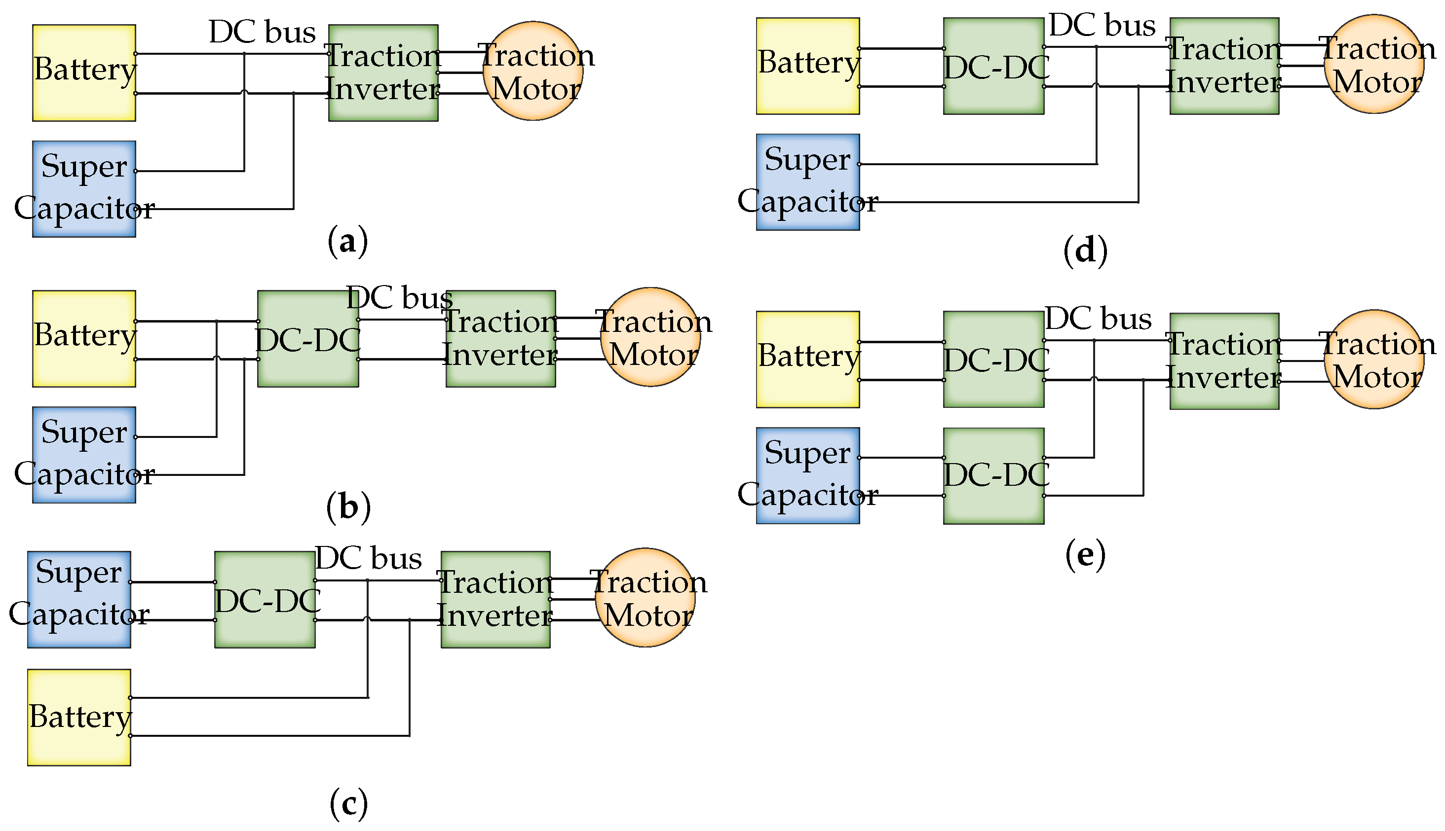
Figure 2.
Block diagram of the proposed sliding forward window strategy in the traction stage.
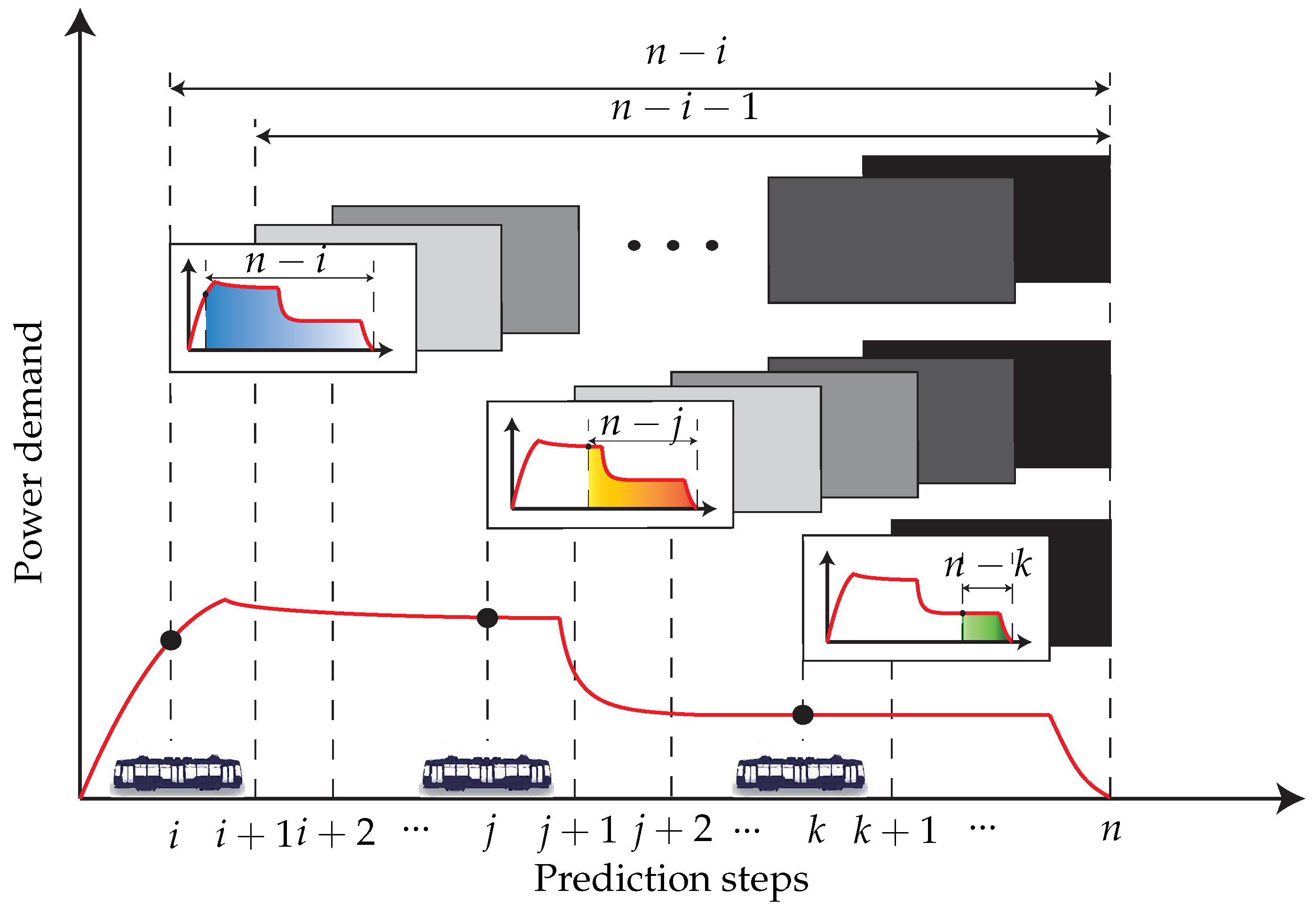
Figure 3.
3 Typical stops in the driving cycle of the Light Rail (LR): (a) speed and (b) power demand profile.
Figure 3.
3 Typical stops in the driving cycle of the Light Rail (LR): (a) speed and (b) power demand profile.

Figure 4.
Circuit diagram of (a) the battery model and (b) the SC model.
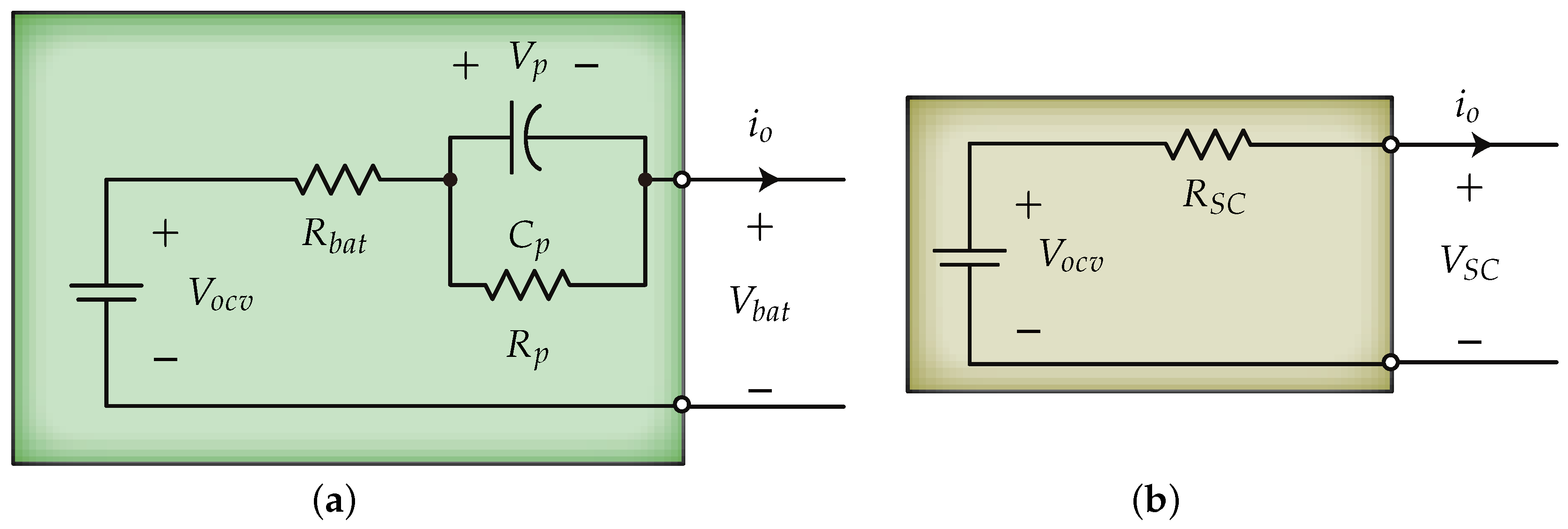
Figure 5.
Parameters and in the 8.5 Ah Thevenin battery circuit model.
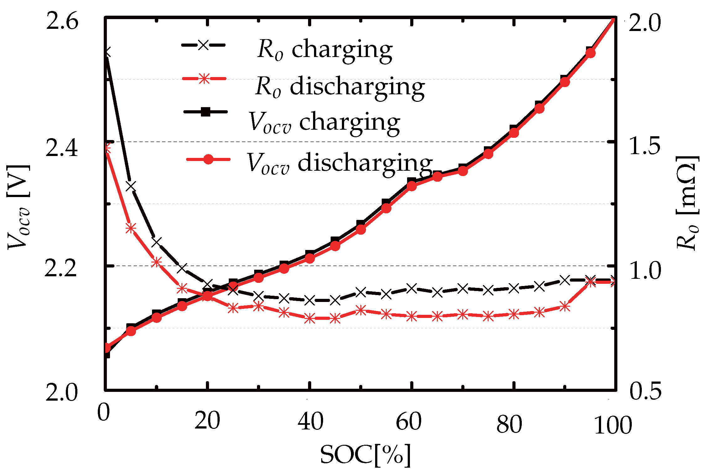
Figure 6.
Simulation results for one-step predictive horizon single-objective optimization energy management systems (EMS with three typical stops in the driving cycle of the LR: (a) battery current and SC current and (b) battery voltage and SC voltage.
Figure 6.
Simulation results for one-step predictive horizon single-objective optimization energy management systems (EMS with three typical stops in the driving cycle of the LR: (a) battery current and SC current and (b) battery voltage and SC voltage.
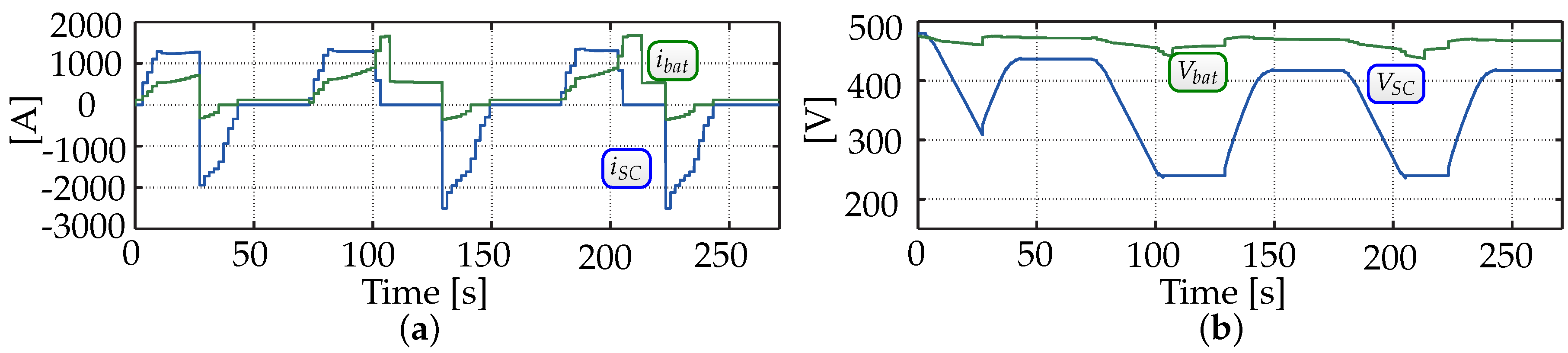
Figure 7.
Simulation results for MPC based two-objectives cost function optimization energy management systems (EMS) with three typical stops in the driving cycle of the LR: (a) battery current and SC current and (b) battery voltage and SC voltage.
Figure 7.
Simulation results for MPC based two-objectives cost function optimization energy management systems (EMS) with three typical stops in the driving cycle of the LR: (a) battery current and SC current and (b) battery voltage and SC voltage.

Figure 8.
Simulation results for the proposed sliding forward window optimization EMS with three typical stops in the driving cycle of the LR: (a) battery current and SC current and (b) battery voltage and SC voltage.
Figure 8.
Simulation results for the proposed sliding forward window optimization EMS with three typical stops in the driving cycle of the LR: (a) battery current and SC current and (b) battery voltage and SC voltage.

Figure 9.
Simulation results for variable predictive horizon optimization EMS with three typical stops in the driving cycle of the LR: (a) battery current and SC current and (b) battery voltage and SC voltage and (c) power mix .
Figure 9.
Simulation results for variable predictive horizon optimization EMS with three typical stops in the driving cycle of the LR: (a) battery current and SC current and (b) battery voltage and SC voltage and (c) power mix .
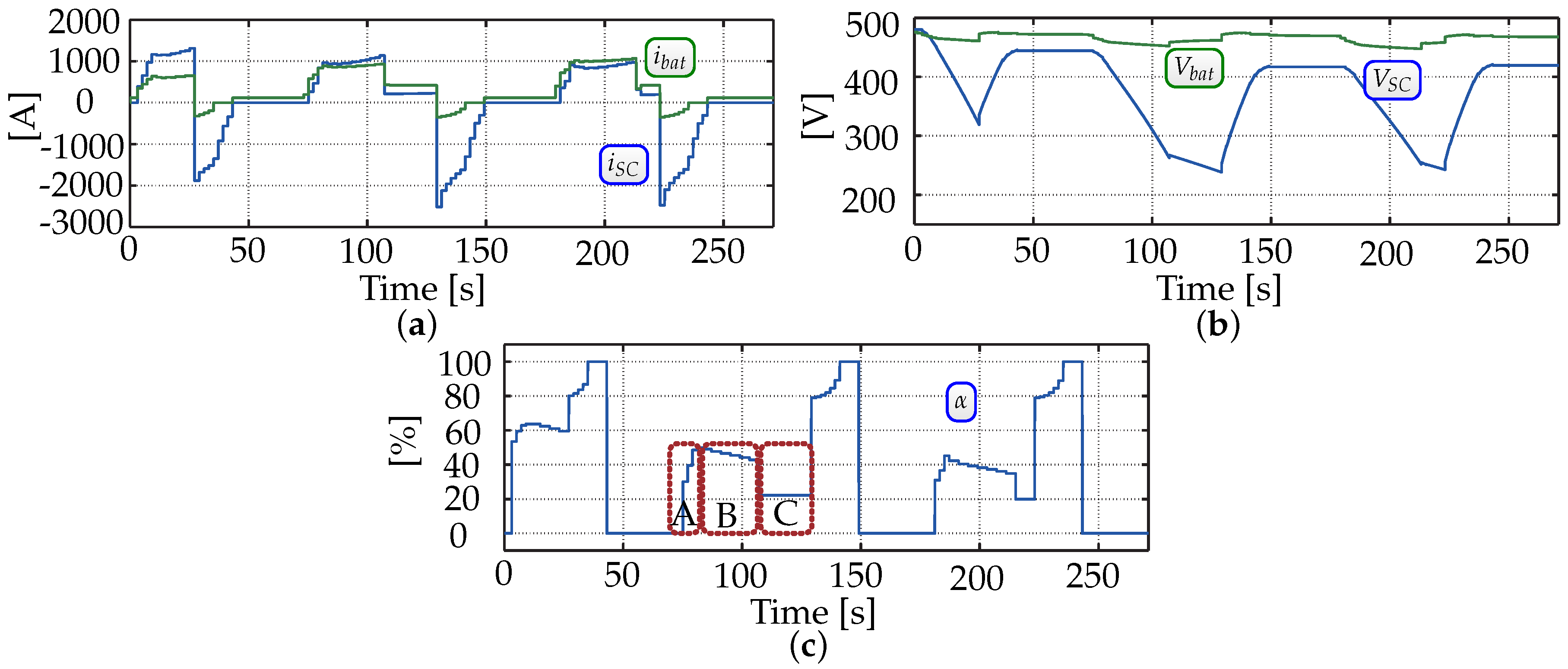
Figure 10.
Experimental setup. A is the LiFePO4 battery pack, B is the SC pack, C is the buck/boost converter, D is the sensor board, E is the dSPACE board, F is the simulation computer, and G is the power of the sensor board and drive board.
Figure 10.
Experimental setup. A is the LiFePO4 battery pack, B is the SC pack, C is the buck/boost converter, D is the sensor board, E is the dSPACE board, F is the simulation computer, and G is the power of the sensor board and drive board.
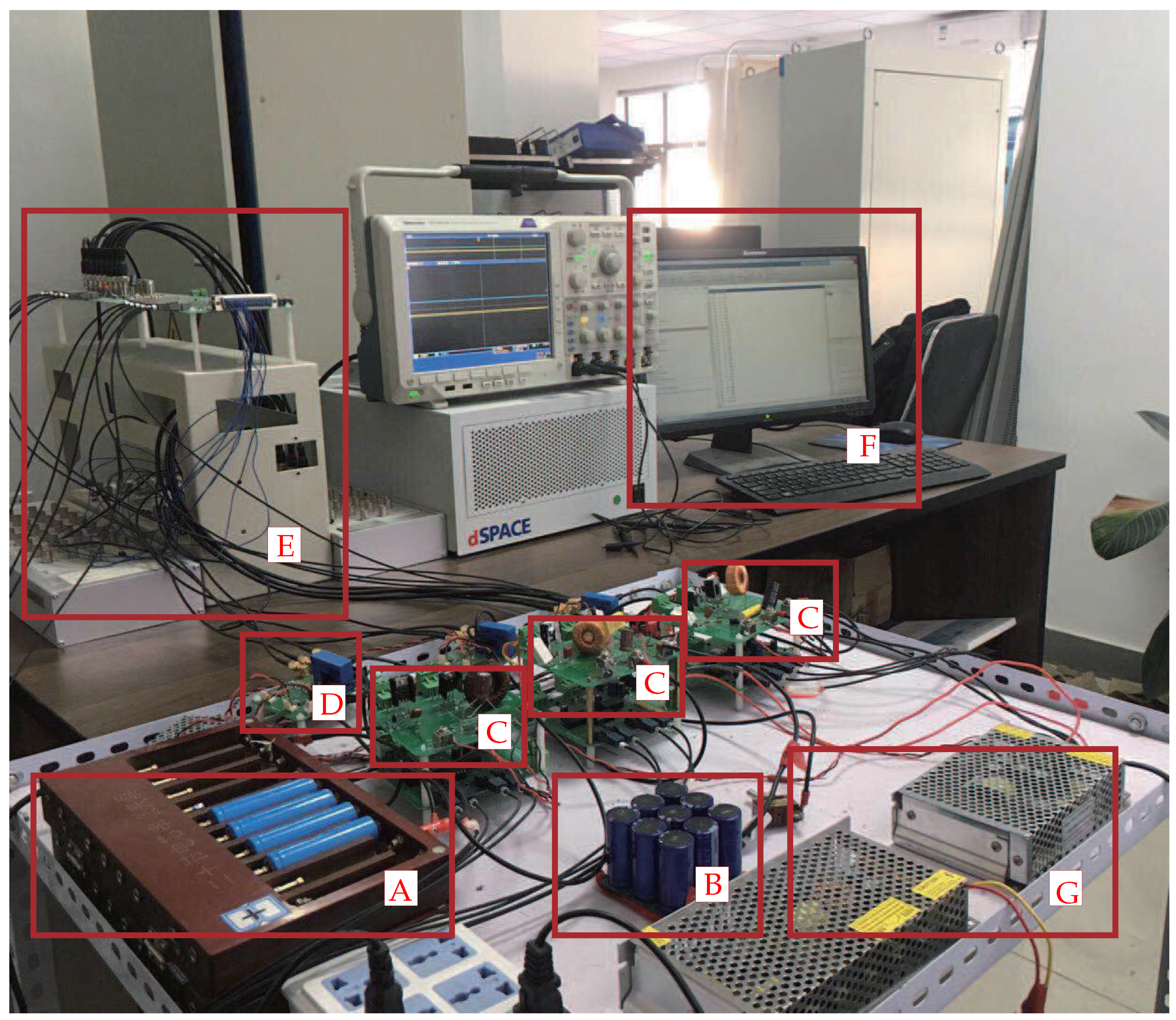
Figure 11.
Experimental results for one-step predictive horizon single-objective optimization EMS with three typical stops in the driving cycle of the LR: SC current, SC voltage, and battery current.
Figure 11.
Experimental results for one-step predictive horizon single-objective optimization EMS with three typical stops in the driving cycle of the LR: SC current, SC voltage, and battery current.
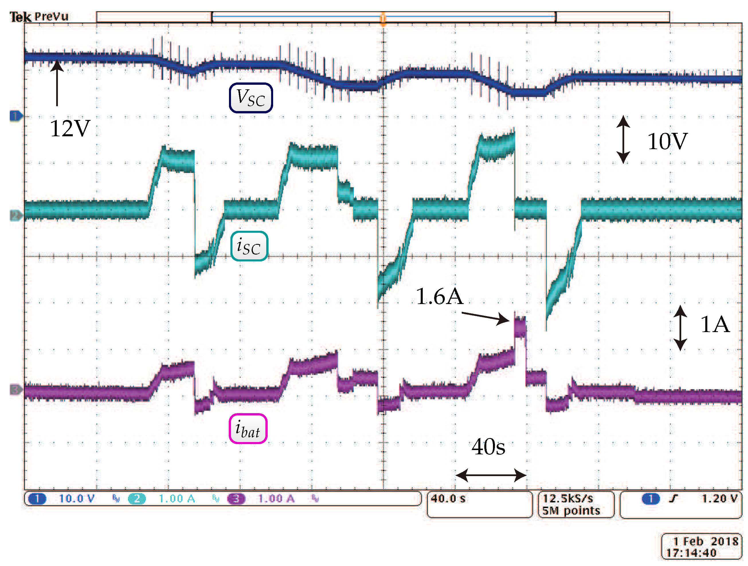
Figure 12.
Experimental results for MPC-based two-objectives cost function optimization EMS with three typical stops in the driving cycle of the LR: SC current, SC voltage, and battery current.
Figure 12.
Experimental results for MPC-based two-objectives cost function optimization EMS with three typical stops in the driving cycle of the LR: SC current, SC voltage, and battery current.
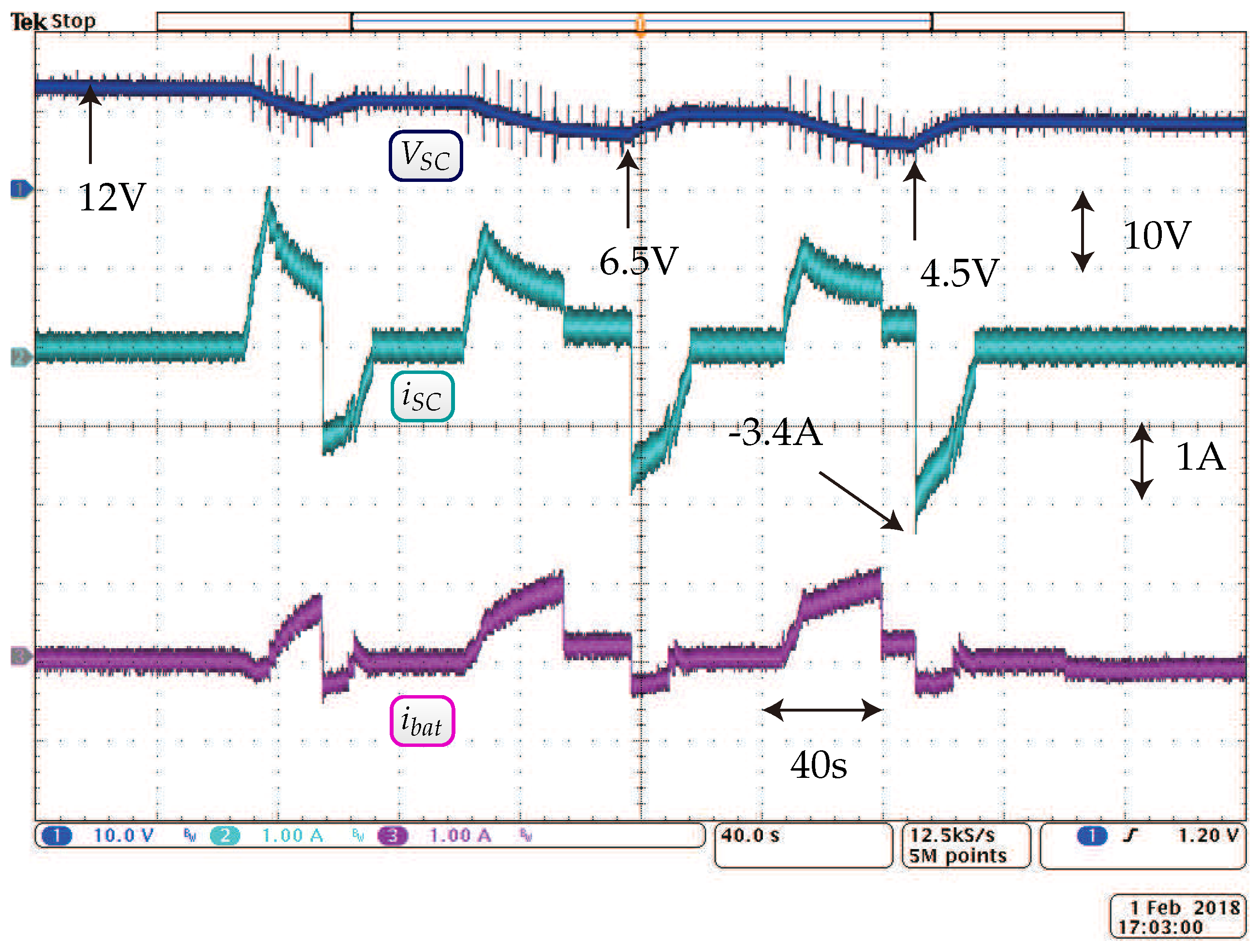
Figure 13.
Experimental results for the proposed sliding forward window optimization EMS with three typical stops in the driving cycle of the LR: SC current, SC voltage, and battery current.
Figure 13.
Experimental results for the proposed sliding forward window optimization EMS with three typical stops in the driving cycle of the LR: SC current, SC voltage, and battery current.


Table 1.
Battery parameters.
| Parameter | Description | Value |
|---|---|---|
| m | Number of cells in series | 200 |
| n | Number of cells in parallel | 20 |
| C [Ah] | Rated Capacitance | 8.5 |
| [V] | Rated Voltage | 2.3 |
| [A] | Charge/discharge current | 85 (10 C) |
Table 2.
Supercapacitor parameters.
| Parameter | Description | Value |
|---|---|---|
| m | Number of modules in series | 10 |
| n | Number of modules in parallel | 20 |
| C [F] | Rated Capacitance | 83 |
| [V] | Rated Voltage | 48 |
| [A] | Absolute Maximum Current | 1150 |
| [m] | Maximum ESR | 10 |
Table 3.
Experimental platform parameters.
| Parameter | Description | Value |
|---|---|---|
| Number of battery cells in series | 4 | |
| Number of battery cells in parallel | 1 | |
| [Ah] | Battery cell rated Capacitance | 1.1 |
| [V] | Battery cell rated Voltage | 3.2 |
| Number of supercapacitor (SC) cells in series | 9 | |
| Number of SC cells in parallel | 1 | |
| [F] | SC cell rated Capacitance | 100 |
| [V] | SC cell rated Voltage | 2.7 |
| L [mH] | Inductor of the converters | 450 |
| [mF] | Capacitor of the converters | 220 |
| [KHz] | Switching frequency | 20 |
| [V] | Bus voltage reference | 20 |
| [s] | Optimization step of the power mix | 2 |
| Power demand reduced ratio | 0.000027 |
© 2018 by the authors. Licensee MDPI, Basel, Switzerland. This article is an open access article distributed under the terms and conditions of the Creative Commons Attribution (CC BY) license (http://creativecommons.org/licenses/by/4.0/).
Share and Cite
MDPI and ACS Style
Cheng, L.; Wang, W.; Wei, S.; Lin, H.; Jia, Z. An Improved Energy Management Strategy for Hybrid Energy Storage System in Light Rail Vehicles. Energies 2018, 11, 423. https://doi.org/10.3390/en11020423
AMA Style
Cheng L, Wang W, Wei S, Lin H, Jia Z. An Improved Energy Management Strategy for Hybrid Energy Storage System in Light Rail Vehicles. Energies. 2018; 11(2):423. https://doi.org/10.3390/en11020423
Chicago/Turabian StyleCheng, Long, Wei Wang, Shaoyuan Wei, Hongtao Lin, and Zhidong Jia. 2018. "An Improved Energy Management Strategy for Hybrid Energy Storage System in Light Rail Vehicles" Energies 11, no. 2: 423. https://doi.org/10.3390/en11020423
Note that from the first issue of 2016, this journal uses article numbers instead of page numbers. See further details here.