The Design of a Permanent Magnet In-Wheel Motor with Dual-Stator and Dual-Field-Excitation Used in Electric Vehicles

School of Electrical and Information Engineering, Tianjin University, No. 92 Weijin Road, Tianjin 300072, China
*
Author to whom correspondence should be addressed.
Energies 2018, 11(2), 424; https://doi.org/10.3390/en11020424
Submission received: 15 January 2018
/
Revised: 8 February 2018
/
Accepted: 8 February 2018
/
Published: 12 February 2018
Abstract
:The in-wheel motor has received more attention owing to its simple structure, high transmission efficiency, flexible control, and easy integration design. It is difficult to achieve high performance with conventional motors due to their dimensions and structure. This paper presents a new dual-stator and dual-field-excitation permanent-magnet in-wheel motor (DDPMIM) that is based on the structure of the conventional in-wheel motor and the structure of both the radial and axial magnetic field motor. The finite element analysis (FEA) model of the DDPMIM is established and compared with that of the conventional in-wheel motor. The results show that the DDPMIM achieves a higher output torque at low speeds and that the flux-weakening control strategy is not needed in the full speed range.
1. Introduction
Electric vehicles (EVs) will soon become a common mode of transport. Electric motors used in EVs have to satisfy many requirements: (1) a high power density and a high torque density; (2) a high output torque at low speeds and a high power output at high speeds; (3) an ability to operate within a wide range of speed in a highly efficient manner; (4) high reliability; and (5) low cost [1]. The in-wheel motor used in an EV has gained more attention owing to its structure, its high transmission efficiency, its flexible control, and its easy integration design [2,3,4].
However, many problems have yet to be solved: Since the motor is mounted inside the wheel, both the riding comfort and the handling safety are affected as the unsprung mass is increased. The structure and size of the motor are limited by the wheel and the structural characteristics of the EV’s suspension. The power density and torque density of EVs also need to be improved.
In order to improve the force indexes of in-wheel motors, many advanced technologies have been employed. External rotor construction has been used to increase the utilization of the inner space of the wheel. Fractional slots have been used to effectively reduce the ends of the windings and the stator tooth harmonic components, improving the utilization of the windings [5]. The axial length of the motor has also been shortened [6,7,8]. High-quality silicon steel plates and permanent magnets (PMs) have been used to decrease loss and improve efficiency. However, dramatic increases in performance have not gained using a conventional in-wheel motor structure. Both the method of excitation and the low inductance make it difficult to output a constant torque under the flux-weakening control strategy at high speed. One alternative that has been considered is the use of switched stator windings [9], whereby two or more different windings are included in one machine. They are connected in series at low speeds and connected in parallel at high speeds [10,11,12,13]. This has improved output torque capacity at low speeds and extended the wide range of high speeds.
Aimed at the existing problems of the conventional in-wheel motor, the dual-winding and dual-field-excitation permanent-magnet in-wheel motor (DDPMIM) is proposed in this paper based on both the structure of the conventional in-wheel motor and the traits of the axial-flux permanent-magnet machine (AFPM). Firstly, this paper describes the structure of the DDPMIM. Secondly, the design of a DDPMIM is described based on the structural dimensions of an in-wheel motor. The winding switching circuit and process are detailed. A finite element analysis (FEA) model of the DDPMIM is established, and the back electromotive force (EMF) waveform, electromagnetic torque, and mechanical characteristics of the motor are analyzed. Results show that the DDPMIM motor has higher torque at low speeds, higher power at high speed, and a lower torque ripple. The flux-weakening control strategy for the DDPMIM is not needed at the full speed range.
2. Work Principle of the DDPMIM
A conventional outer rotor in-wheel motor with a fractional slot winding and a surface-mount Halbach permanent-magnet array from a previous work was studied [14]. Table 1 provides the main parameters of the conventional in-wheel motor. The rated power of the prototype is 8.5 kW and the rated speed is 650 r/min (Figure 1). According to electrical machines theory, the diameter of the air gap should be designed such that there is a substantial amount of unused space inside the motor. Thus, it is possible that a conventional in-wheel motor can be redesigned as a DDPMIM due to the free space inside the motor.
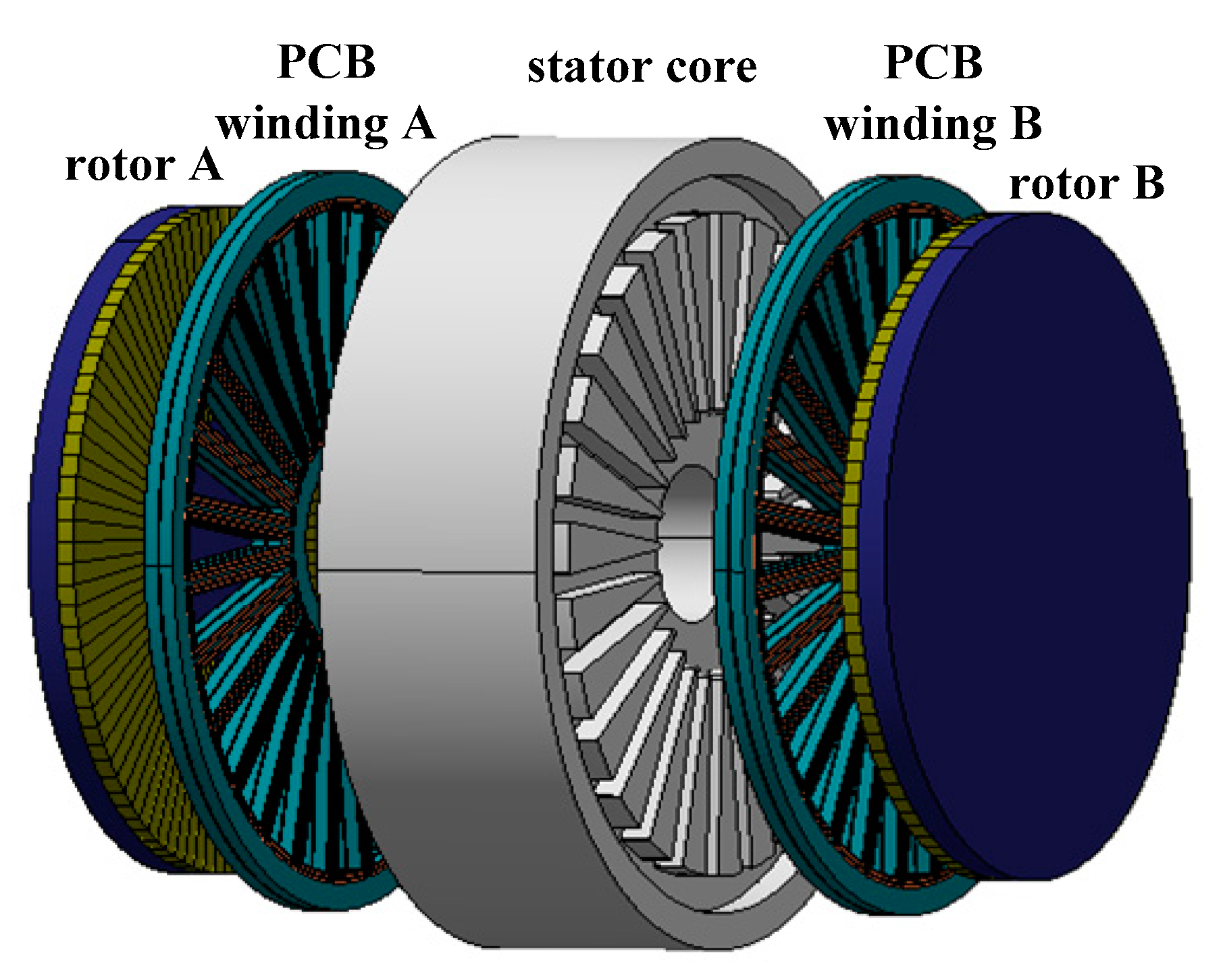
The DDPMIM designed in this study is shown in Figure 2. It consists of two units: the radial flux motor unit and the AFPM unit. The former unit includes Stator Core 1, a copper wire winding, a rotor yoke, and PMs that are magnetized in the radial direction. Stator Core 1 is made up of a laminated silicon steel sheet. This unit requires the diameter of the air gap in the traditional structure to be as large as possible. The AFPM unit includes Halbach array PMs, Printed Circuit Board (PCB) Winding A, PCB Winding B, a motor cover, and Stator Core 2, which is made of soft magnetic composites (SMCs). The AFPM unit is divided into two parts, the left part and the right part.
The ideal torque-speed curve of the DDPMIM is shown in Figure 3. T1 > T2 > T3, and n1 < n2 < n3. The copper wire winding, PCB Winding A, and PCB Winding B are connected in series when the DDPMIM operates within a low-speed range. The output torque of the motor here is T1. The terminal voltage of the motor approaches the limit of the inverter output voltage when the motor speed reaches n1. The PCB Winding B should be disconnected to increase the motor speed. The copper wire winding and PCB Winding A are connected in series when the DDPMIM operates within a middle-speed range. The output torque of the motor here is T2. Similarly, the copper wire winding works alone when the DDPMIM operates within a high-speed range. The output torque of the motor here is T3.
3. Design of DDPMIM
3.1. Analysis of Back EMF
Based on the theory of the permanent-magnet synchronous motor (PMSM), the induced voltage of the copper conductor is proportional to the back EMF. The structure of the PCB winding is shown in Figure 4. If the air-gap flux density in the PMSM is a constant B, the induced voltage for the copper conductor can be deduced as
where l is the length of the copper conductor, ω is the angular velocity, Ra is the inner radius of the conductor, and Rb is the outside radius.
A high Rb and a low Ra yields a high induced voltage according to Equation (1). If Ra equals zero, the induced voltage is proportional to Rb squared. In order to increase the back EMF, the key is to increase the outside diameter of the PCB and make full use of the space near the outside edge and increase the magnetic flux density as much as possible.
3.2. Selection of Slots and Poles
To reduce the back EMF harmonics, the ends of the windings, and the cogging torque in the PMSM, the fractional-slot concentrated windings are considered. After the selection of the slots/poles combination, the electrical angle α between slots equals to
where Z is the number of slots, and p is the number of pole pairs.
Results of [5] show that it is useful to improve the sinusoidal property of the back EMF waveform and increase the utilization of windings, as Z and p satisfy the relationship as follows:
The number of slots Z can be deduced as
where i has as low a value as possible.
For a PMSM with fractional-slot windings, an unbalanced magnetic pull will be produced when the denominator of the slots per pole per phase q is an even number [15].
3.3. Structure of AFPM
The copper wire winding and the PCB winding are connected in series when DDPMIM operates within a low- or middle-speed range. To keep the current density in the two windings equal to each other, the area of their current-carrying conductors should be equivalent or close. The AFPM without teeth is considered first because it has no cogging torque. Figure 5 shows a cross section of the magnetic circuit of the AFPM with a PCB stator and no teeth.
The flux density Bm of PM at the working point and the air-gap flex density Bδ can be deduced respectively as [16]
where σ is the flux leakage coefficient, δ is the air-gap length, KF is the direction coefficient of the air-gap flux density, μr is the relative magnetic permeability, hM is the length of the PM in the direction of magnetization, and Br is the remanent flux density of PM.
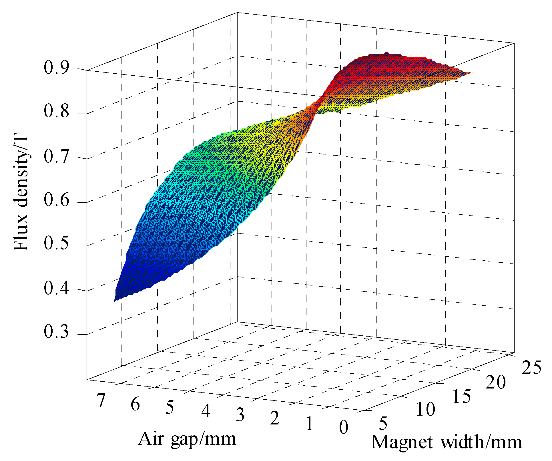
Equations (5) and (6) indicate that Bm and Bδ are related to δ and hM. The relationships between Bδ, δ, and hM is shown in Figure 6.
Figure 6 shows that, as hM increases, Bδ first increases and then decreases. The magnetomotive force in the magnetic circuit increased linearly with hM. Reluctance also increased as the permeability of the PM approached the air.
Under the limitation of the space, an AFPM with a PCB stator and no teeth was designed. The model was established according to the calculation result based on Figure 6. The harmonic spectra were calculated via fast Fourier transform (FFT). The fundamental amplitude of the back EMF of the DDPMIM was 153.5 V at 650 r/min. Compared with the conventional in-wheel motor, the DDPMIM had a 10.9% higher amplitude. The output torque of the DDPMIM was 143 N·m, which is only a 15.3% improvement at the same rated current. The air-gap flux density was relatively lower due to the large equivalent air-gap length. In addition, the back EMF and the output torque decreased due to the lower outside radius and the length of the PCB winding. Therefore, the structure of the AFPM with a PCB stator and no teeth is not suitable for DDPMIM.
The structure of an AFPM was designed with teeth and a PCB stator and is shown in Figure 7. The PM disc is arranged in a 45° Halbach array. There are four magnets in one pole.
4. Finite Element Analysis (FEA) of Conventional In-Wheel Motor and DDPMIM
4.1. FEA Model
The formulations of 3D FEA are
where A and φ are the magnetic vector and electric scalar potentials, respectively, Ja is the armature current density, and M is the magnetization of the permanent magnet.
The DDPMIM in this paper is based on the dimensions shown in Table 1. Table 2 provides the main parameters of the DDPMIM.
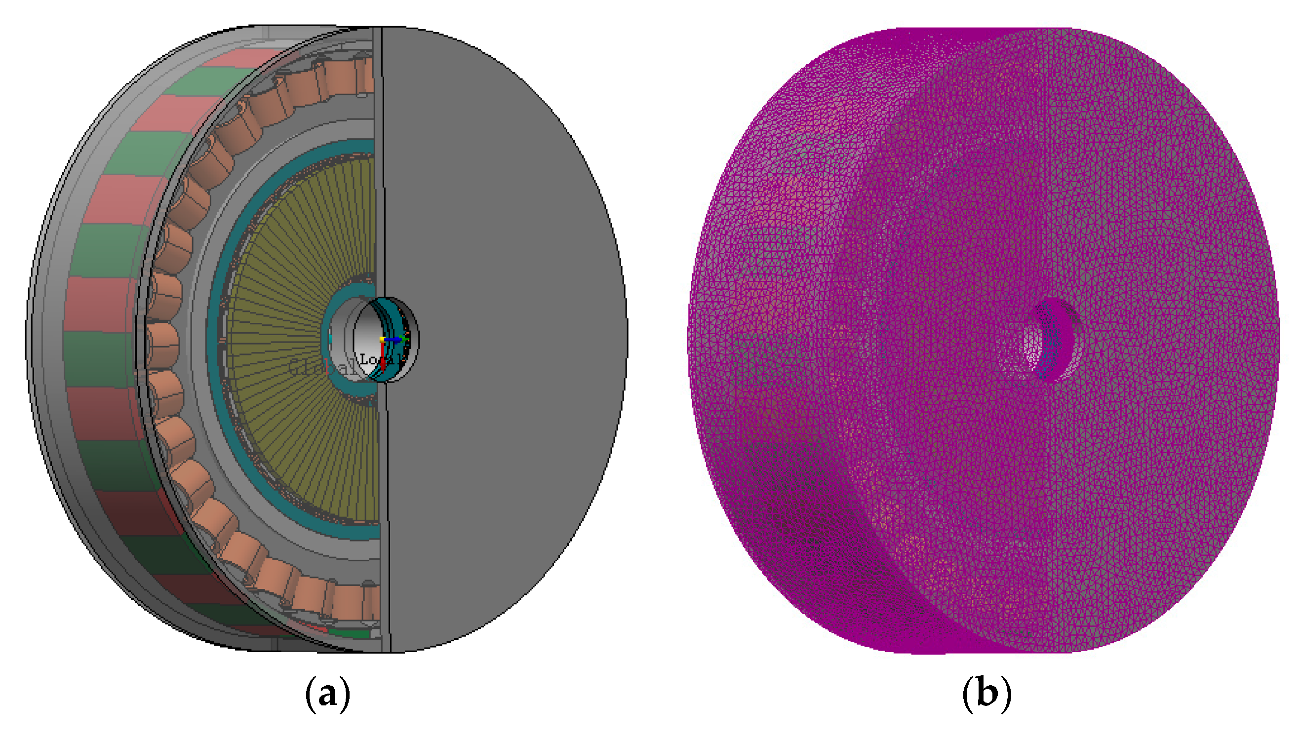
It is difficult to calculate the coupling characteristics of the magnetic field between the axial flux motor unit and the radial flux motor unit. The FEA model of the DDPMIM is built, as shown in Figure 8a. The initial 3D mesh is also shown in Figure 8b. In the 3D FEA, the model is divided into a mesh of tetrahedrally shaped elements. The accuracy of the solution highly depends on the size of the mesh elements. The adaptive mesh method is used in the FEA software, but it is essential to apply a maximum element size to different components. The calculation accuracy and time are taken into consideration. The maximum element sizes of each component of the DDPMIM are shown in Table 3.
4.2. Analysis of Magnetic Field
The magnetic field of the DDPMIM was calculated. Figure 9 shows the flux density distribution in the radial flux motor. Figure 9a shows the flux density distribution in the calculation of the static magnetic field at no load. Figure 9b shows the flux density distribution at some point in the calculation of the transient magnetic field. The winding current is twice the rated current (29.5 A). The rotor speed is 650 r/min. In both cases, the flux density in the area near the inner diameter of the Stator Core 1 is zero. In addition, the diameter of the Halbach PMs of AFPM is smaller than the inner diameter of the Stator Core 1, and the magnetic field generated by Halbach PMs along the axis. Based on the above analysis, there is no magnetic coupling between the two motor units. The difficulty in control will not be increased. Figure 10 shows an arrow plot of the magnetic flux of one-fourth of the AFPM unit.
The air gap flux density waveforms of the axial flux motor unit and the radial flux motor unit were obtained, as shown in Figure 11. The latter is a trapezoidal waveform, which leads to torque decline with ripple under the sinusoidal line current control method. The former has better features such as high magnitude and a fine sinusoidal property according to the Halbach array.
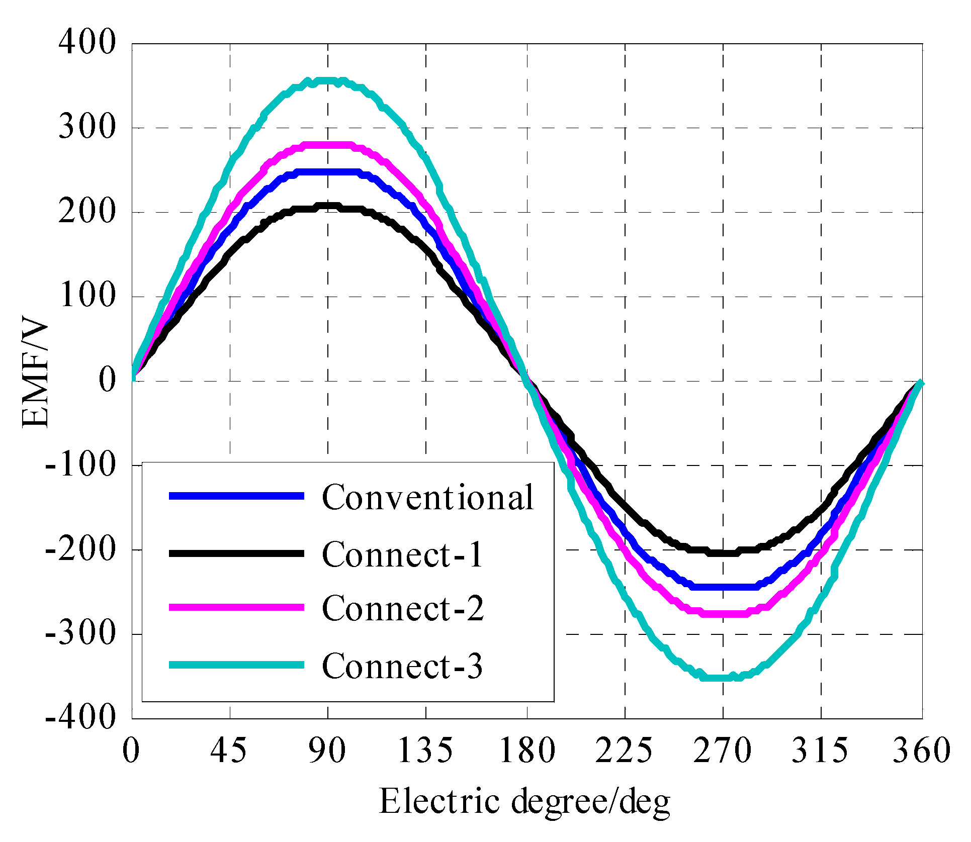
Figure 12 presents no-load back EMF waveforms at the rated speed of the two in-wheel motors. Connect-1 represents the copper wire winding, PCB Winding A, and PCB Winding B connected in series. Connect-2 represents the copper wire winding and PCB Winding A connected in series. Connect-3 represents the copper wire winding alone.
The harmonic spectra were calculated via FFT, and results are given in Table 4. Comparison of the fundamental amplitude (F amp) and the total harmonics distortion (THD) shows that the back EMF waveform is improved by connecting the axial flux motor unit.
4.3. Analysis of Load Characteristic
The circuit of winding switch is shown in Figure 13. There are four switches in one phase used to change the connecting forms of the copper wire winding, PCB Winding A, and PCB Winding B. The DDPMIM operating state, the winding connection state, and the switches state are shown in Table 5. Take Phase A for example. The copper wire winding, PCB Winding A and PCB Winding B are connected in series with KA1 and KA3 turned on and with KA2 and KA4 turned off when the DDPMIM operates within a low-speed range. The terminal voltage increases with an increase in speed. When this voltage approaches the inverter limited voltage, the copper wire winding and PCB Winding A are connected in series with KA1 and KA4 turned on and with KA2 and KA3 turned off. The copper wire winding works independently with KA2 and KA4 turned on and KA1 and KA3 turned off when the DDPMIM operates within a high-speed range.
The conventional in-wheel motor and the DDPMIM are set with the same rated current. Torque-speed curves are shown in Figure 14.
For the conventional in-wheel motor, the output torque is 122 N·m at the rated current when the speed is below 1000 r/min. At 1000 r/min, the terminal voltage approaches the limit voltage value of the inverter. The flux-weakening control strategy must be employed as the speed increases. The magnetic field of the conventional in-wheel motor is excited by surface-mount PM and the d-axis inductance is small. A large current will be required in the high-speed range. The efficiency of the motor will be decreased. At 1200 r/min, the output torque is only 50 N·m and the output power is 6.8 kW. When the DDPMIM operates from 0 to 700 r/min, the copper wire winding, PCB Winding A, and PCB Winding B are connected in series, and the output torque is 175 N·m. This is a 43.4% increase. From 700 to 950 r/min, the copper wire winding and PCB Winding A are connected in series, and the output torque is 140 N·m. From 950 to 1300 r/min, the copper wire winding works alone, and the output torque is 95 N·m. At 1200 r/min, the output power is 11.9 kW. This is an 75% increase. From 950 to 1100 r/min, the output torque of the DDPMIM is lower. A higher current is needed to increase the output torque.
For comparison purposes, the two motors are loaded with the same rated current. At 650 r/min, the output power densities of the conventional in wheel motor and DDPMIM are 213 W/kg (0.915 W/cm3) and 254 W/kg (0.915 W/cm3), respectively. At the rated condition, the output power densities are 170 W/kg (0.732 W/cm3) and 252 W/kg (1.28 W/cm3), respectively.
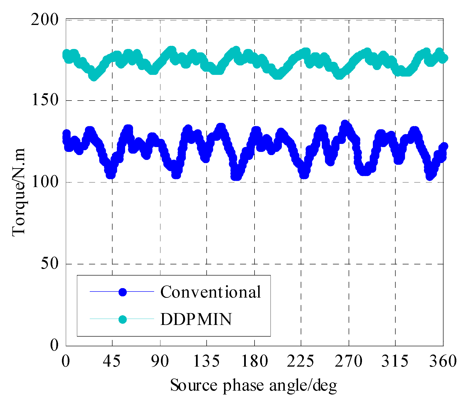
The PMSM suffers from torque pulsation, which is the main contributing factor of noise and vibration in EVs. As in-wheel motors are directly installed in the wheels of the vehicles, unsprung weight will be increased. This will worsen the noise and vibration of EVs, especially at low speeds. The torque at the rated speed (650 r/min) and the rated current of the conventional in-wheel motor and DDPMIM were calculated, as shown in Figure 15. The torque pulsation of the conventional in-wheel motor is 23.2%, while that of the DDPMIM is 10.6%. Torque pulsation is thus reduced by 54.3%, improving overall ride comfort.
5. Conclusions
The DDPMIM is able to operate within a full speed range without adding flux weakening control. Within the limited operating voltage of the inverter, different connection forms of windings are used. The DDPMIM is shown here to have a greater output torque and less torque ripple than those of the conventional in-wheel motor, especially at low speeds.
The connection status of the windings, except for the speed and the limited operating voltage of the inverter, mainly depend on the back EMF. The back EMF of each unit and the ratios between them must be carefully designed. However, the space for the axial flux motor unit is limited. It is important to increase the back EMF produced by the PCB winding.The arrangement of the PCB winding and the PM array must take this into account.
While the DDPMIM designed in this study may not be optimal, based on the FEM results, it outperforms the conventional structure in-wheel motor and therefore shows promise for future applications.
Acknowledgments
This work is funded by National Natural Science Foundation of China, No. 51577125.
Author Contributions
Peng Gao and Xiaoyuan Wang proposed the new structure of the in-wheel motor. Penag Gao and Yuxi Gu conducted the main work of design and simulation.
Conflicts of Interest
The authors declare no conflict of interest.
References
- Chan, C.C. The State of the art of electric and hybrid vehicles. Proc. IEEE 2002, 90, 247–275. [Google Scholar] [CrossRef]
- Rahman, K.M.; Patel, N.R.; Ward, T.G.; Nagashima, J.M.; Caricchi, F.; Crescimbini, F. Application of direct-drive wheel motor for fuel cell electric and hybrid electric vehicle propulsion system. IEEE Trans. Ind. Appl. 2006, 42, 1185–1192. [Google Scholar] [CrossRef]
- Chau, K.T.; Chan, C.C.; Liu, C. Overview of Permanent-Magnet Brushless Drives for Electric and Hybrid Electric Vehicles. IEEE Trans. Ind. Electron. 2008, 55, 2246–2257. [Google Scholar] [CrossRef] [Green Version]
- Cao, R.; Mi, C.; Cheng, M. Quantitative Comparison of Flux-Switching Permanent-Magnet Motors with Interior Permanent Magnet Motor for EV, HEV, and PHEV Applications. IEEE Trans. Magn. 2012, 48, 2374–2384. [Google Scholar] [CrossRef]
- Wang, J.; Patel, V.I.; Wang, W. Fractional-Slot Permanent Magnet Brushless Machines with Low Space Harmonic Contents. IEEE Trans. Magn. 2013, 50, 1–9. [Google Scholar] [CrossRef]
- Chen, Y.G.; Pan, Y.L.; He, X. Magnetomotive force in permanent magnet synchronous machine with concentrated fractional-slot winding. Trans. China Electrotech. Soc. 2010, 25, 30–36. [Google Scholar]
- Zhu, Z.Q.; Xia, Z.P. Analytical modeling and finite element computation of radial vibration force in fractional-slot permanent magnet brushless machines. IEEE Trans. Ind. Appl. 2010, 46, 1908–1918. [Google Scholar] [CrossRef]
- Mo, H.C. The Cogging Torque Analysis of Permanent Magnet Servo Motor with Fractional-slot Concentrated Windings. Micromotors 2011, 44, 1–5. [Google Scholar]
- Nipp, E.; Norberg, E. On the feasibility of switched stator windings in permanent magnet motors for traction drives. In Proceedings of the 1998 ASME/IEEE Joint, Railroad Conference, Philadelphia, PA, USA, 15–16 April 1988; pp. 33–39. [Google Scholar]
- Huang, H.; Chang, L. Electrical two-speed propulsion by motor winding switching and its control strategies for electric vehicles. IEEE Trans. Veh. Technol. 1999, 48, 607–618. [Google Scholar] [CrossRef]
- Wang, Y.; Xu, Y. Winding Switching Analysis of Dual-Stator Permanent Magnet Brushless DC Motors Used in Electric Vehicles. Trans. China Electrotech. Soc. 2014, 29, 98–103. [Google Scholar]
- Li, Y.; Bobba, D.; Sarlioglu, B. Design and Performance Characterization of a Novel Low-Pole Dual-Stator Flux-Switching Permanent Magnet Machine for Traction Application. IEEE Trans. Ind. Appl. 2016, 52, 4304–4314. [Google Scholar] [CrossRef]
- Shamsi-Nejad, M.A.; Nahid-Mobarakeh, B.; Pierfederici, S.; Meibody-Tabar, F. Fault Tolerant and Minimum Loss Control of Double-Star Synchronous Machines under Open Phase Conditions. IEEE Trans. Ind. Electron. 2008, 55, 1956–1965. [Google Scholar] [CrossRef]
- Wang, X.Y.; Gao, P.; Wang, G.J. The Design of Halbach Array Permanent Magnet for In-wheel Motor. In Proceedings of the 2013 ICEMS, Busan, Korea, 26–29 October 2013. [Google Scholar]
- Wang, X.Y.; Li, Z.M. Analysis of Unilateral Magnetic Force in Permanent Magnet Synchronous Machine with Fractional-slot Winding. Micromotors 2013, 46, 9–12. [Google Scholar]
- Tang, R.Y. Modern Permanent Magnet Machines—Theory and Design; China Machine Press: Beijing, China, 1997; pp. 314–320. [Google Scholar]
Figure 1.
Prototype of in-wheel motor.
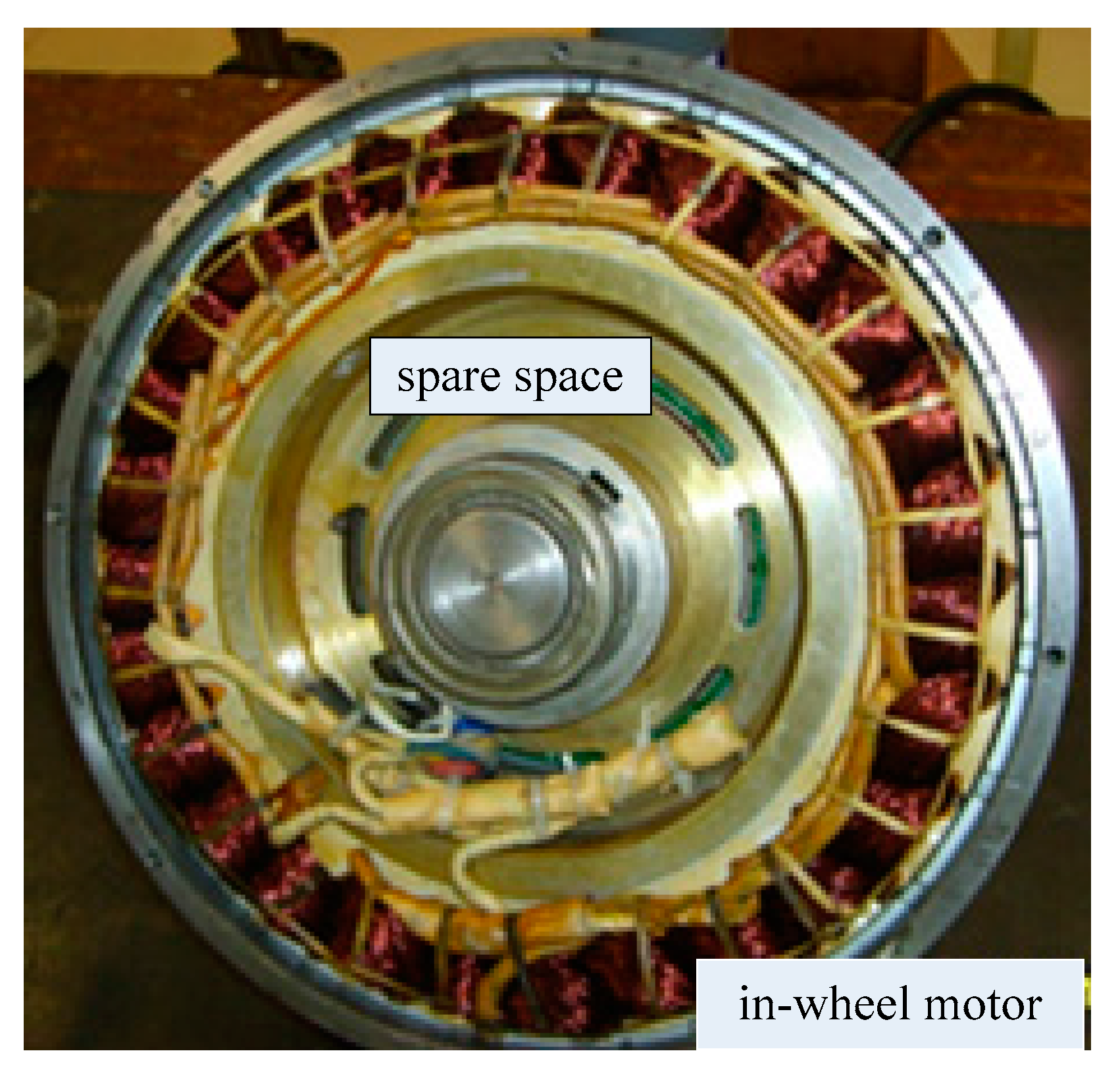
Figure 2.
The dual-stator and dual-field-excitation permanent-magnet in-wheel motor (DDPMIM) structure. PM: permanent magnet; PCB: Printed Circuit Board.
Figure 2.
The dual-stator and dual-field-excitation permanent-magnet in-wheel motor (DDPMIM) structure. PM: permanent magnet; PCB: Printed Circuit Board.
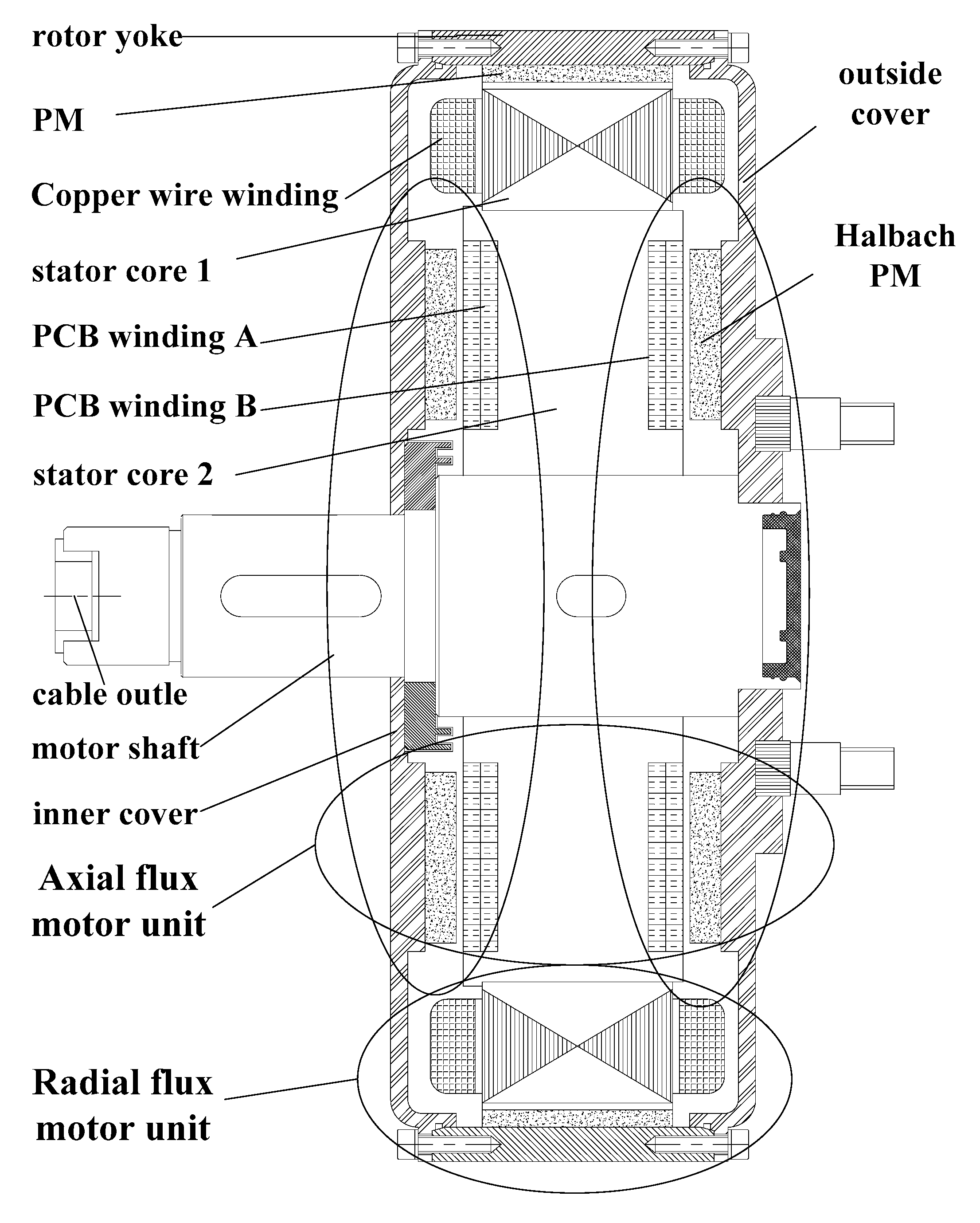
Figure 3.
The DDPMIM ideal torque-speed curve.
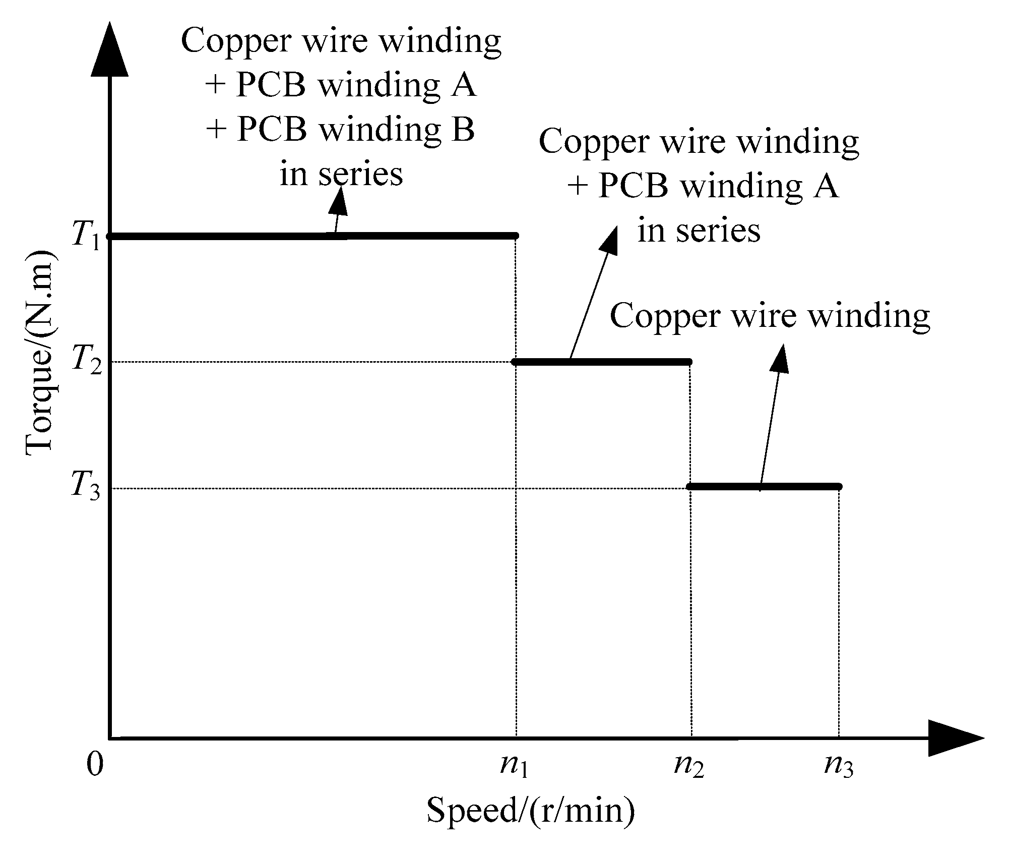
Figure 4.
DDPMIM winding PCB.
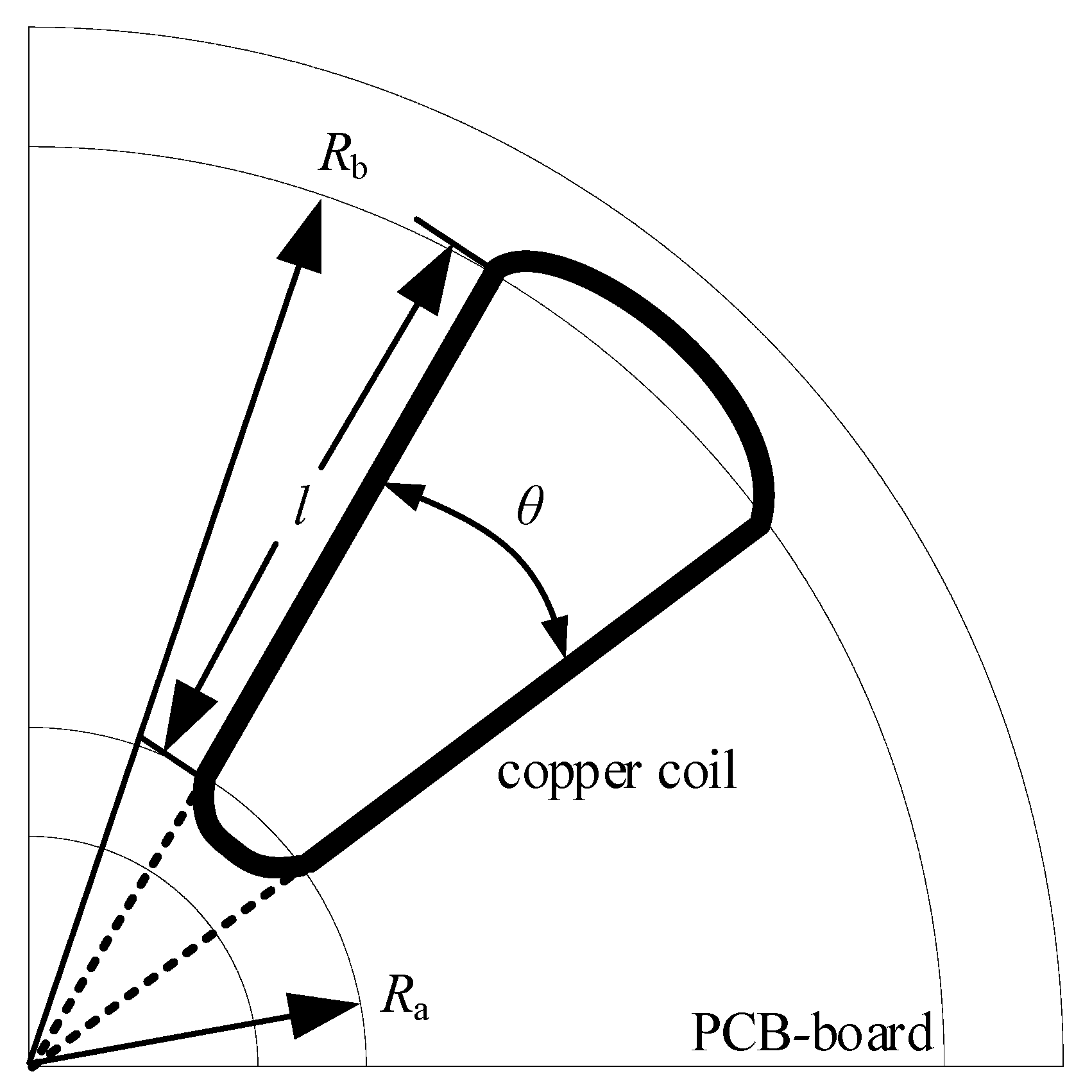
Figure 5.
Analytical model of the generalized magnetic circuit.
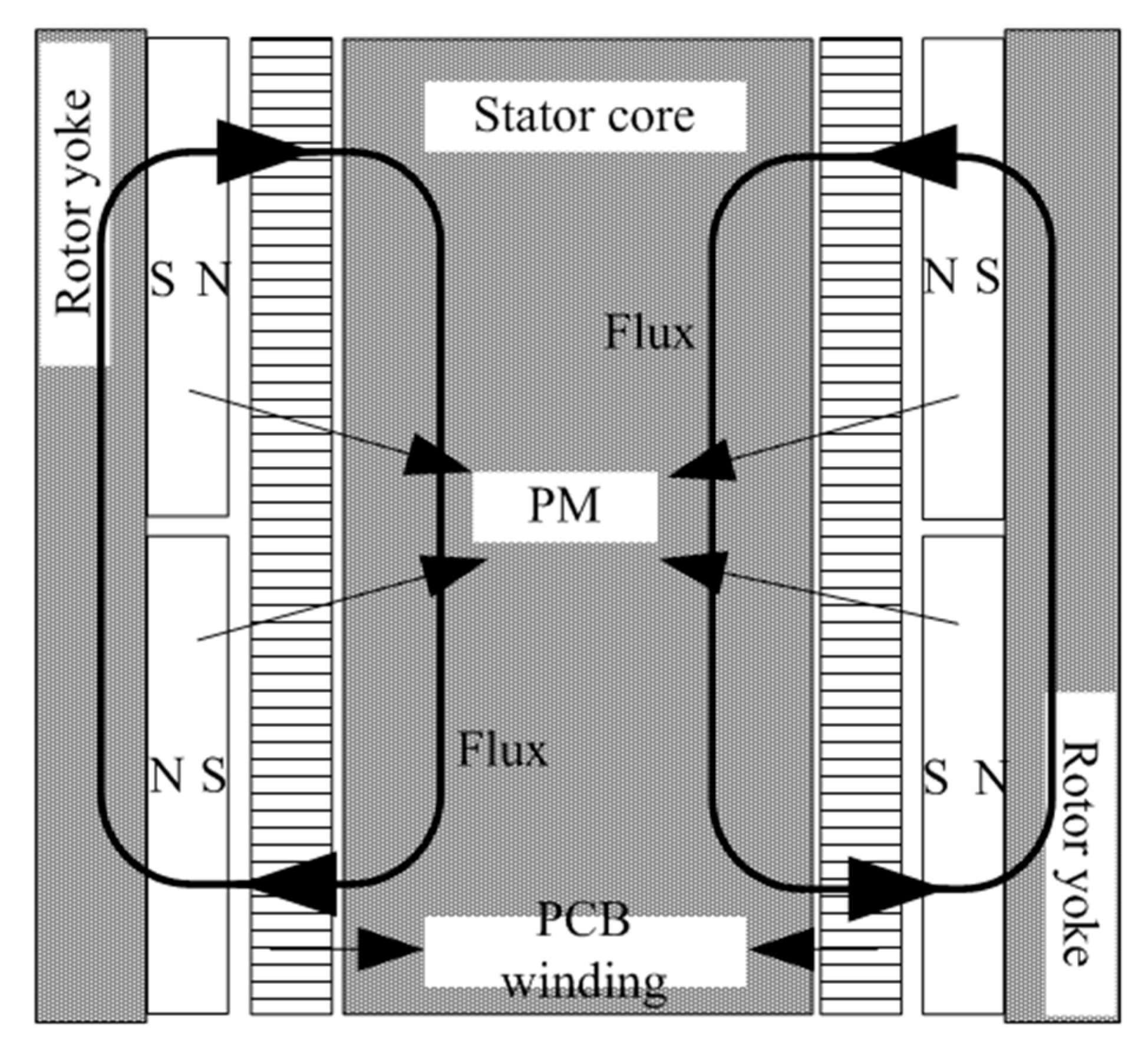
Figure 6.
Air gap flux density.

Figure 7.
3D view of the axial-flux permanent-magnet machine (AFPM) with a PCB stator and teeth.

Figure 8.
3D model of the DDPMIM. (a) 3D FEA model; (b) 3D mesh.

Figure 9.
Flux density distribution. (a) No-load; (b) Load.
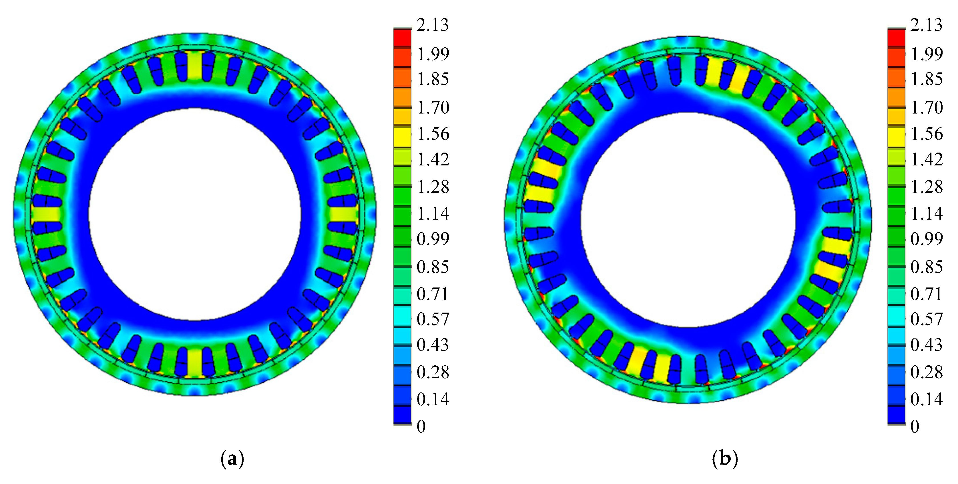
Figure 10.
Axial magnetic flux arrow plot.

Figure 11.
Flux density distribution.

Figure 12.
Back electromotive force (EMF) waveforms.

Figure 13.
Circuit of the winding switch.
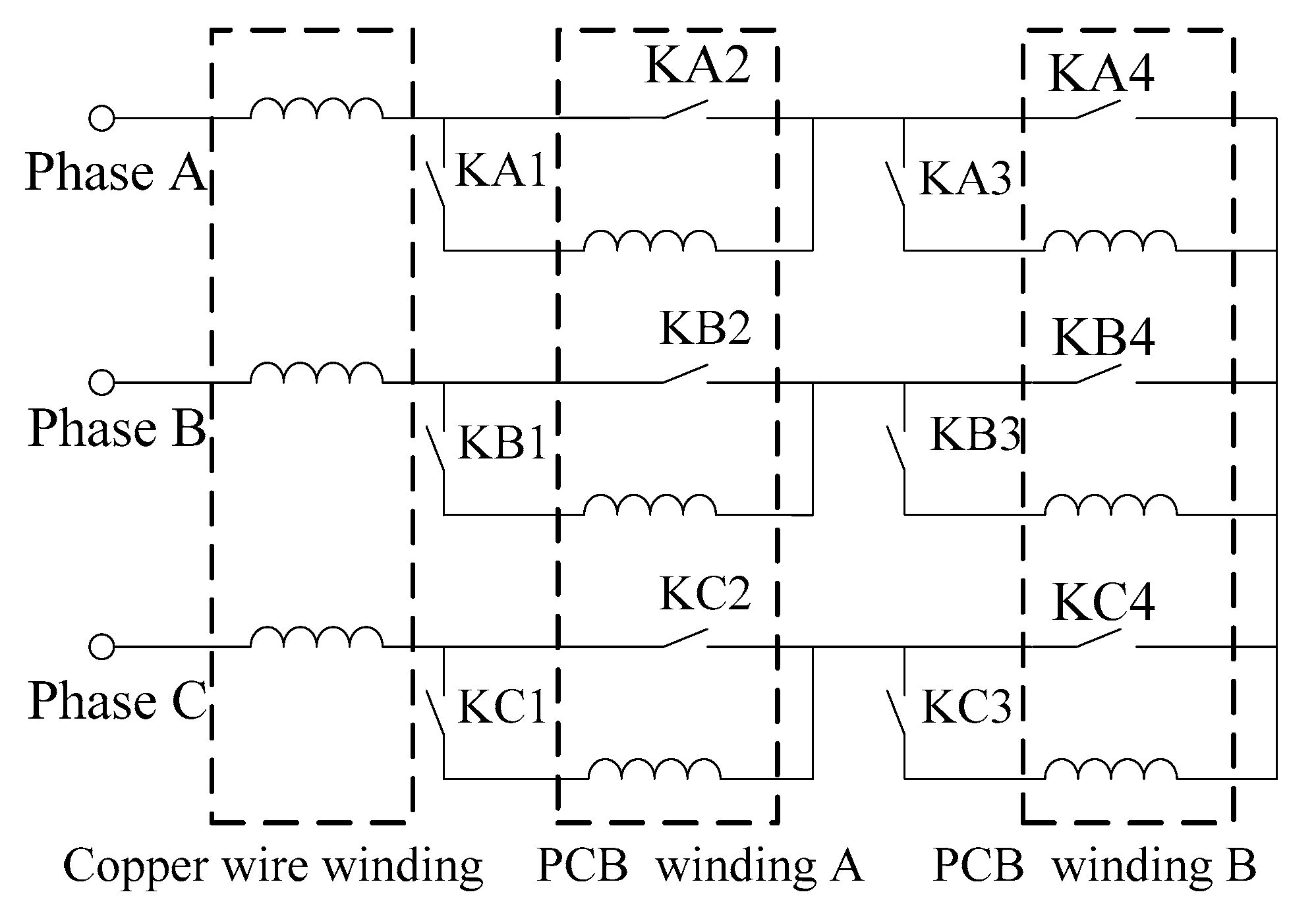
Figure 14.
Torque-speed curves.

Figure 15.
Torque curves.

Table 1.
Main parameters of the conventional in-wheel motor prototype.
| Parameter | Value | Unit |
|---|---|---|
| Rated power | 8.5 | kW |
| Rated speed | 650 | r/min |
| Max speed | 1300 | r/min |
| Slot number | 27 | - |
| Pole number | 24 | - |
| Stator diameter | 296.4 | mm |
| Stator inner diameter | 195 | mm |
| Rotor diameter | 328 | mm |
| Rotor inner diameter | 298 | mm |
| Number of turns of winding | 13 | - |
| Thickness of permanent magnets | 5 | mm |
Table 2.
Main parameters of the DDPMIM.
| Parameter | DDPMIM-Value | Unit |
|---|---|---|
| Rated power | 12 | kW |
| Slot number | 36 | - |
| Pole number | 32 | - |
| Stator core 1 diameter | 296.4 | mm |
| Stator core 1 inner diameter | 210 | mm |
| Rotor diameter (radial flux unit) | 328 | mm |
| Rotor inner diameter (radial flux unit) | 298 | mm |
| Stator 2 core diameter | 210 | mm |
| Stator 2 core inner diameter | 45 | mm |
| PCB winding diameter | 195 | mm |
| PCB winding inner diameter | 60 | mm |
| Rotor (Halbach PMs) diameter | 190 | mm |
| Rotor (Halbach PMs) inner diameter | 70 | mm |
| Number of turns of copper wire winding | 9 | - |
| Number of turns of PCB winding (A or B) | 8 | - |
| Thickness of PMs | 4.5 | mm |
| Thickness of Halbach PMs | 5 | mm |
Table 3.
Maximum element size of the DDPMIM.
| Components | Maximum Element Size-Value | Unit |
|---|---|---|
| Airbox of the whole model | 5 | mm |
| Air gap of the radial flux unit | 0.5 | mm |
| Air gap of the AFPM unit | 0.5 | mm |
| Stator core 1 | 1.5 | mm |
| Stator core 2 | 1.5 | mm |
| Rotor yoke | 1.5 | mm |
| PMs | 2 | mm |
Table 4.
Main parameters of the in-wheel motor.
| Item | Conventional | Connect-1 | Connect-2 | Connect-3 |
|---|---|---|---|---|
| F_amp | 251.0 | 207.9 | 282.2 | 356.4 |
| THD | 5.6% | 5.2% | 2% | 1.7% |
Table 5.
Switch state.
| DDPMIM Operating State | Low Speed Range | Middle Speed Range | High Speed Range | |
|---|---|---|---|---|
| Windings Connection (In Series) | copper wire winding, PCB Winding A, PCB Winding B | copper wire winding, PCB Winding A | copper wire winding | |
| Switches State | ON | KA1, KA3; KB1, KB3; KC1, KC3 | KA1, KA4; KA1, KA4; KA1, KA4 | KA2, KA4; KA2, KA4; KA2, KA4 |
| OFF | KA2, KA4; KB2, KB4; KC2, KC4 | KA2, KA3; KA2, KA3; KA2, KA3 | KA1, KA3; KA1, KA3; KA1, KA3 | |
© 2018 by the authors. Licensee MDPI, Basel, Switzerland. This article is an open access article distributed under the terms and conditions of the Creative Commons Attribution (CC BY) license (http://creativecommons.org/licenses/by/4.0/).
Share and Cite
MDPI and ACS Style
Gao, P.; Gu, Y.; Wang, X. The Design of a Permanent Magnet In-Wheel Motor with Dual-Stator and Dual-Field-Excitation Used in Electric Vehicles. Energies 2018, 11, 424. https://doi.org/10.3390/en11020424
AMA Style
Gao P, Gu Y, Wang X. The Design of a Permanent Magnet In-Wheel Motor with Dual-Stator and Dual-Field-Excitation Used in Electric Vehicles. Energies. 2018; 11(2):424. https://doi.org/10.3390/en11020424
Chicago/Turabian StyleGao, Peng, Yuxi Gu, and Xiaoyuan Wang. 2018. "The Design of a Permanent Magnet In-Wheel Motor with Dual-Stator and Dual-Field-Excitation Used in Electric Vehicles" Energies 11, no. 2: 424. https://doi.org/10.3390/en11020424
Note that from the first issue of 2016, this journal uses article numbers instead of page numbers. See further details here.