1. Introduction
As one of the most promising renewable energy resources to be used in the world, wind energy has attracted the attention of many researchers [
1,
2,
3,
4]. With the fast development of power electronics, the fully-rated permanent magnet synchronous generator (PMSG) and partially-rated doubly-fed induction generator (DFIG)-based wind energy conversion systems (WECSs) are the ones mainly used in the wind energy market, since they have the ability of variable-speed constant-frequency (VSCF) operation. The advantages of the small volume and low cost of the back-to-back (BTB) power converter are endowed to DFIG-based wind turbines (DFIG-WTs). However, when these wind turbines approach the end of their lifetime, various types of faults may happen, which result in downtime. Especially for offshore wind applications, where terrible weather conditions and high maintenance cost are present, a longer period of downtime is caused, which leads to more energy and economic losses.
According to [
5], although the electronic control system only accounts for around 1% of the total cost of a wind turbine system, 13% of the failures of wind turbines are caused by the faults in power electronic devices. Although flexible control of DFIG-WT is realized by using power electronic converters, the reliability of the system is deteriorated, owing to the fragility of the semiconductor switches in these converters. In a conventional three-phase AC/DC/AC BTB converter, which consists of a grid-side converter (GSC) and a rotor-side converter (RSC), twelve power switches are applied, with six of them installed in GSC and the other six used in RSC for power regulation. Once a switch is open circuited, the corresponding entire bridge arm will be idle, and the control of the current through this phase will be lost. In order to ride through this kind of fault, three major types of fault-tolerant converter topologies were proposed, including the strategies employing multi-level converters, redundant back-up switches and DC-bus midpoint connection. Considering the merits of minimizing the switching losses and simplifying the circuit configuration, the last option is widely applied, and it is to be utilized in this paper for fault tolerance purposes.
By connecting the DC-bus midpoint to the phase originally connected to the faulty bridge arm, only four switches are to be controlled in this fault-tolerant topology, and the current in the faulty phase is automatically controlled according to the fact that the summation of three-phase currents equals zero. This topology based on four switches is called the four-switch three-phase (FSTP) topology, with respect to its six-switch three-phase (SSTP) counterpart. Despite the simple circuit structure and high reliability of the FSTP topology, the utilization rate of the DC-bus voltage is much lower than that of SSTP, and fluctuation in the upper and lower capacitor voltages exists due to the current in the faulty phase flowing through one of the two DC-link capacitors all the time. In [
6], a
dq mathematical model of the FSTP voltage source rectifier (VSR) was first derived for control design proposes. Detailed mathematical deduction of the FSTP VSR model was presented, and the “reduced Park transformation” was applied. A comprehensive modelling of a non-redundant fault-tolerant inverter with the method of DC-bus midpoint connection was performed in [
7], and the generalized switching functions were proposed. An optimized modulation approach was raised in [
8] for the post-fault pulse width modulation (PWM) rectifiers to minimize the capacitor currents so that the current stresses on the capacitors are mitigated. Besides, the modelling, modulation and control of an FSTP rectifier were comprehensively analysed in [
9], with a novel linear modulation function proposed. Moreover, the zero voltage distribution in the FSTP converter has been studied to analyse the performance in [
10] in terms of the AC current ripple, the common voltage (CMV) and the current stress on the DC-link capacitor. On top of that, the applications of FSTP topology in induction motor drives [
11,
12], brushless DC (BLDC) motor drives [
13,
14] and PMSGs [
15,
16,
17] were extensively investigated. However, there is a rare literature concentrating on improving the performance of FSTP converter-based DFIG-WT. In [
18,
19], only the faulty case in the GSC was considered, and the other parts of the system were assumed to be intact.
With the purpose of controlling the operation of DFIG-WT, the rotor speed and position information is required. Usually, mechanical and optical sensors such as tachometers and optical encoders are utilized to measure the rotor speed and position [
20]. However, with the installation of speed and position sensors, the hardware complexity, cost and the size of the system are increased, and regular maintenance of these sensors is detrimental to the system reliability [
21]. In order to avoid these disadvantages, the control algorithm called “sensorless control” was put forward to directly obtain the rotor speed and position by only measuring the voltages and currents [
22]. In general, there are two approaches in the sensorless techniques for electrical machines, which are based on signal injection and mathematical modelling. The former approach is usually applied in permanent magnet (PM) machines for zero or low speed scenarios, and its performance is greatly deteriorated when the machine runs at high speed. For induction machine (IM) applications, the corresponding sensorless control methods are usually based on the precise system model.
Different from the other deterministic schemes used for speed/position sensorless control of electrical machines, the Kalman filter (KF) [
23] is a kind of stochastic approach. In terms of nonlinear systems such as IMs, PM machines and doubly-fed induction machines (DFIMs), an updated version of the KF stochastic algorithm called the EKF is usually applied for estimating the non-measured parts of the system [
24,
25]. Since EKF has good robustness to disturbances such as process and measurement noises in a complicated nonlinear system, the reliability of this method can be ensured even if uncertainties are induced in the estimation process [
24,
25].
An optimized EKF was proposed by using a real-coded genetic algorithm for properly selecting the noise covariance and weight matrices to guarantee filter stability and accuracy in speed estimation of an IM drive in [
26]. In [
27], the EKF algorithms were applied in speed sensorless control of IMs by combining field-oriented control (FOC) and direct-torque control (DTC). Additionally, a braided EKF was proposed for sensorless control of IMs in [
28], and challenging parameter and load variations in a wide speed range were considered to verify the algorithm. The convergence analysis of EKF for sensorless control of IM was presented in [
29]. In spite of a number of research works and applications of EKF algorithms in IMs, there is a rare literature focusing on speed and position sensorless control of DFIGs by using EKF. The research on the EKF algorithm for DFIM was first conducted in [
30], and a suitable model was proposed for estimating the rotor position, speed and mechanical torque of DFIG. In [
31], an EKF was proposed as the rotor position estimator, and the observability of the DFIG was analysed. In [
32], a comprehensive analysis of the performance of an EKF was carried out for the non-augmented, partially-augmented and augmented state models of DFIG, respectively, and the best performance was obtained when applying the proposed augmented state estimator. Furthermore, a sensorless optimal power control of brushless DFIG (BDFIG) based on EKF was investigated in [
33]. However, all these literature works mentioned only took one faulty scenario into consideration, which may be ineffective for post-fault operation of DFIG at the late stage of service time.
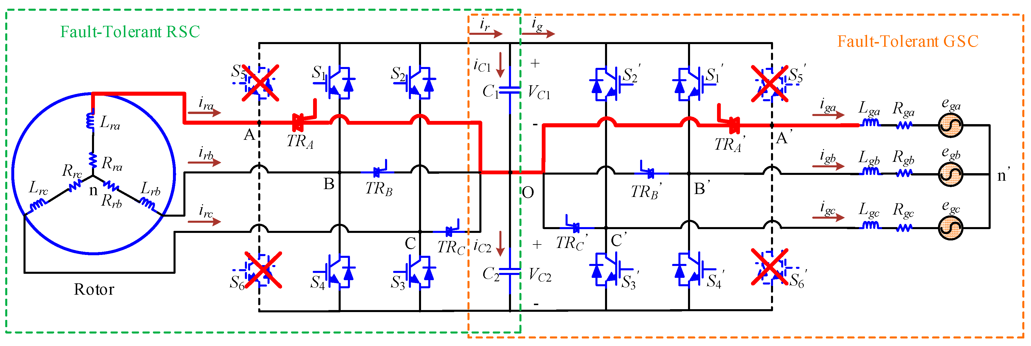
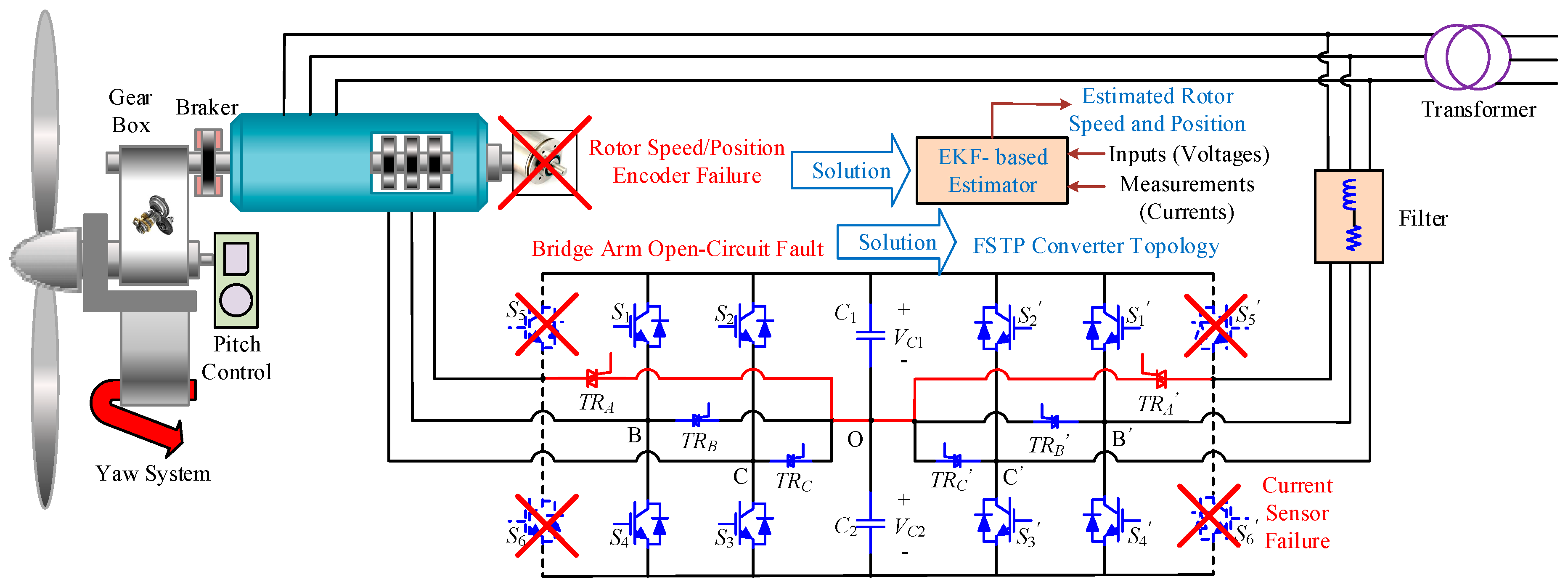
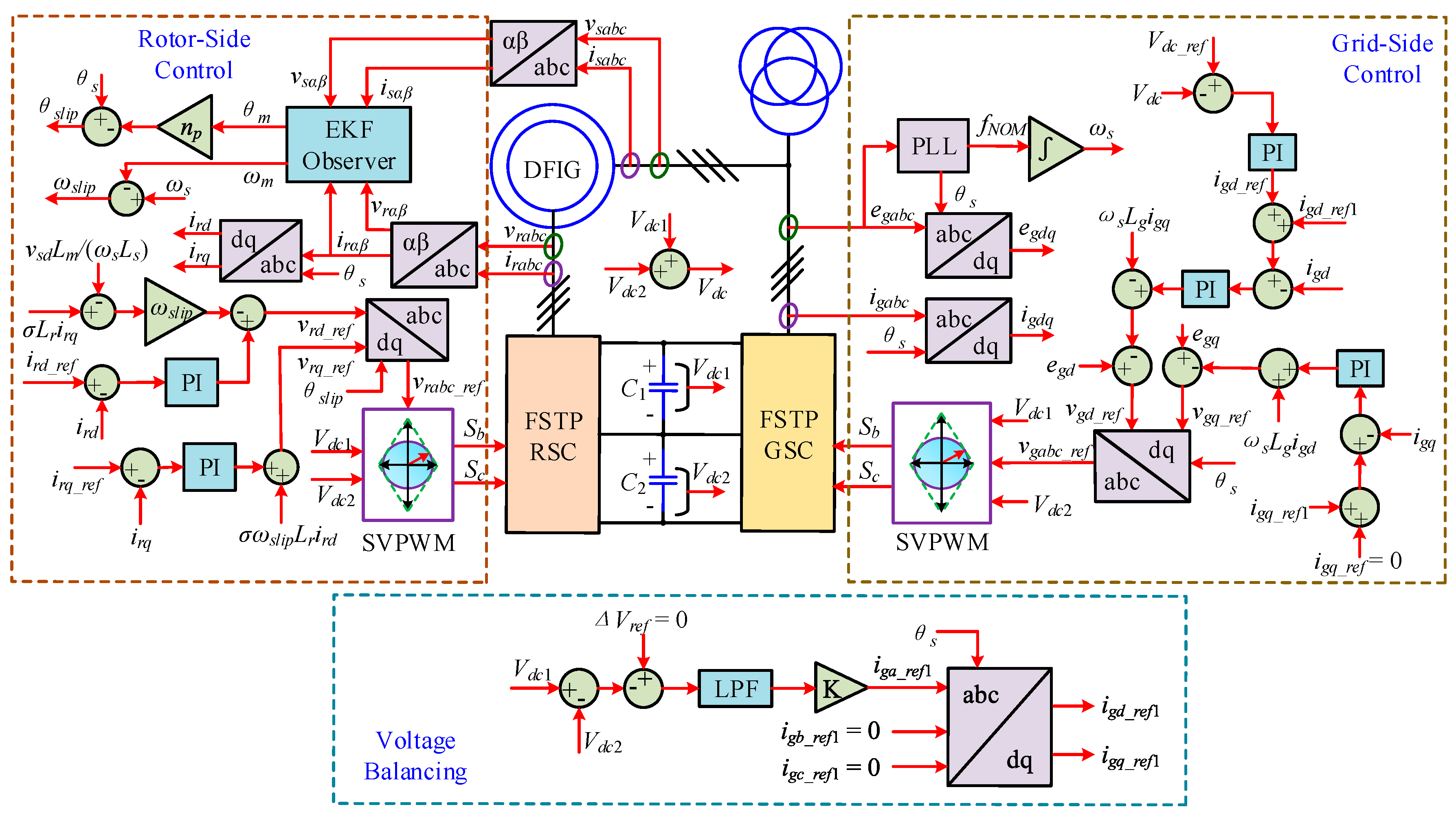
This paper investigates the hybrid fault-tolerant operation of late-stage offshore DFIG-WT, where open-circuit faults in the bridge arms of the BTB converter and position encoder failure occur simultaneously, which has not been researched before. The EKF algorithm is combined with the FSTP BTB converter in a DFIG-WT to ride through the hybrid fault case mentioned. The seventh-order dynamic model of DFIG is deeply analysed, and the robustness of EKF to measurement noises is proven in the sensorless control process. In addition, a simplified space vector PWM (SVPWM) technique and a voltage balancing control scheme are proposed for the FSTP BTB converter to improve the post-fault performance of DFIG-WT without complicating the control process. The hybrid fault scenario considered in this paper is displayed in
Figure 1.
The organization of the paper is shown as follows: In
Section 2, the DFIG dynamic model is explained. The EKF estimator for DFIG is presented in
Section 3. Then, the configuration, modulation and control of the FSTP BTB converter are illustrated in
Section 4. After that, the sensorless control strategy for an FSTP BTB converter-based DFIG-WT by using the EKF algorithm is discussed in
Section 5. In
Section 6, the simulation results are shown with descriptions and analysis. Finally, the conclusion is given in
Section 7.
2. DFIG Dynamic Model
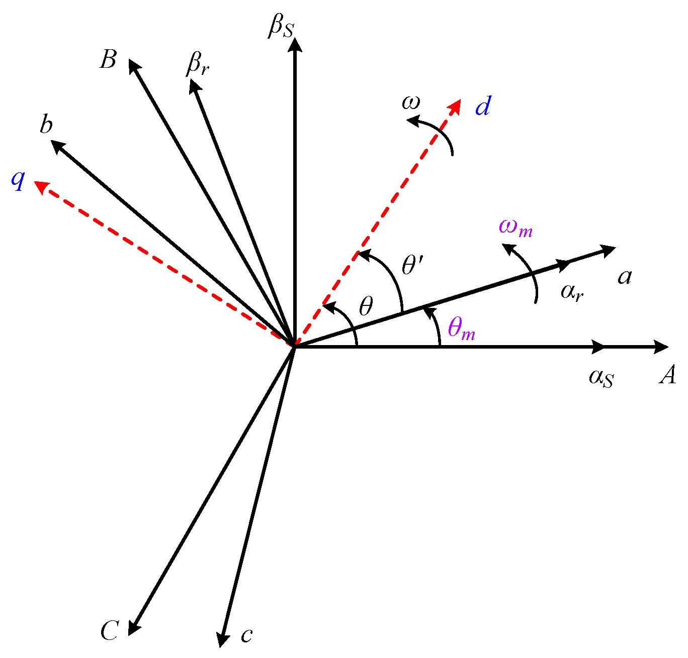
Similar to other three-phase AC machines, the DFIG model expressed in a three-phase coordination system is complex, since it contains the characteristics of high order, multiple variables, nonlinearity, strong coupling and time variations. In this case, it is difficult to control the operation of the system. In order to effectively control the active and reactive power of DFIG, it is feasible to implant the vector control (VC) technique. The relationships among the three-phase stationary reference frame (
ABC), three-phase rotor reference frame (
abc), two-phase stationary reference frame (
αβs), two-phase rotor reference frame (
αβr) and two-phase arbitrary rotating reference frame (
dq) are illustrated in
Figure 2.
By transforming the three-phase currents to an arbitrary rotating two-phase reference frame, namely the
dq reference frame, the independent control of the active and reactive power can be realized by controlling the current components on the
d- and
q-axis. In a
dq synchronous reference frame, the dynamic model of DFIG can be expressed by the following equations.
Equations (1)–(4) are the voltage equations, flux equations, electromagnetic torque equation and kinetic equation, respectively.
From
Figure 2, it can be seen that the information of the rotor speed
ωm and position
θm is of paramount importance since it is directly related to the transformation of the rotor variables to the
dq frame. In the normal case, a speed or position encoder is utilized for obtaining the values of
ωm and
θm. In order to increase the system reliability, the encoder is eliminated in this paper, and a seventh-order state space model of DFIG is established for designing the estimator of the rotor speed and position to realize sensorless control. The state
x(
t) consists of the
dq stator and rotor currents, rotor angular speed, rotor position and the mechanical torque. The stator currents in the
αβs reference frame and the rotor currents in the
αβr reference frame can be directly measured, and the
αβ stator and rotor voltages can be used as the inputs of the system. The state
x(
t), measurements
y(
t) and inputs
u(
t) of the DFIG system can be expressed as shown below.
The electrical variables of DFIG are in the
dq synchronous reference frame, whereas those in the inputs and measurements are oriented in the
αβ stationary reference frame, and the transformation between the reference frames is dependent on the rotor position
θm, leading to the nonlinearity of the DFIG model. Under this circumstance, the state variable model is expressed in the general form with the rate of change in the state
dx(
t)/
dt, which can be regarded as the process function
f(
x(
t),
u(
t)) as shown in (6).
where
σ is the leakage coefficient, and it can be expressed as:
The measurement matrix of the system can be derived as
6. Simulation Results
To verify the proposed fault-tolerant strategy by using FSTP converters and the EKF estimator-based sensorless control scheme for a late-stage DFIG-WT with hybrid faults of converter bridge arm open circuit and speed/position sensor failure, simulation studies are carried out in MATLAB/Simulink2017a (MathWorks, Natick, MA, USA). A 1.5-MW DFIG-WT is studied in the simulation, and the initial rotor speed is set as 1.2 pu, with the initial rotor position equal to zero, and the sampling time
Ts is set as 5 μs. The system parameters for the 1.5-MW DFIG-WT are shown in
Table 5.
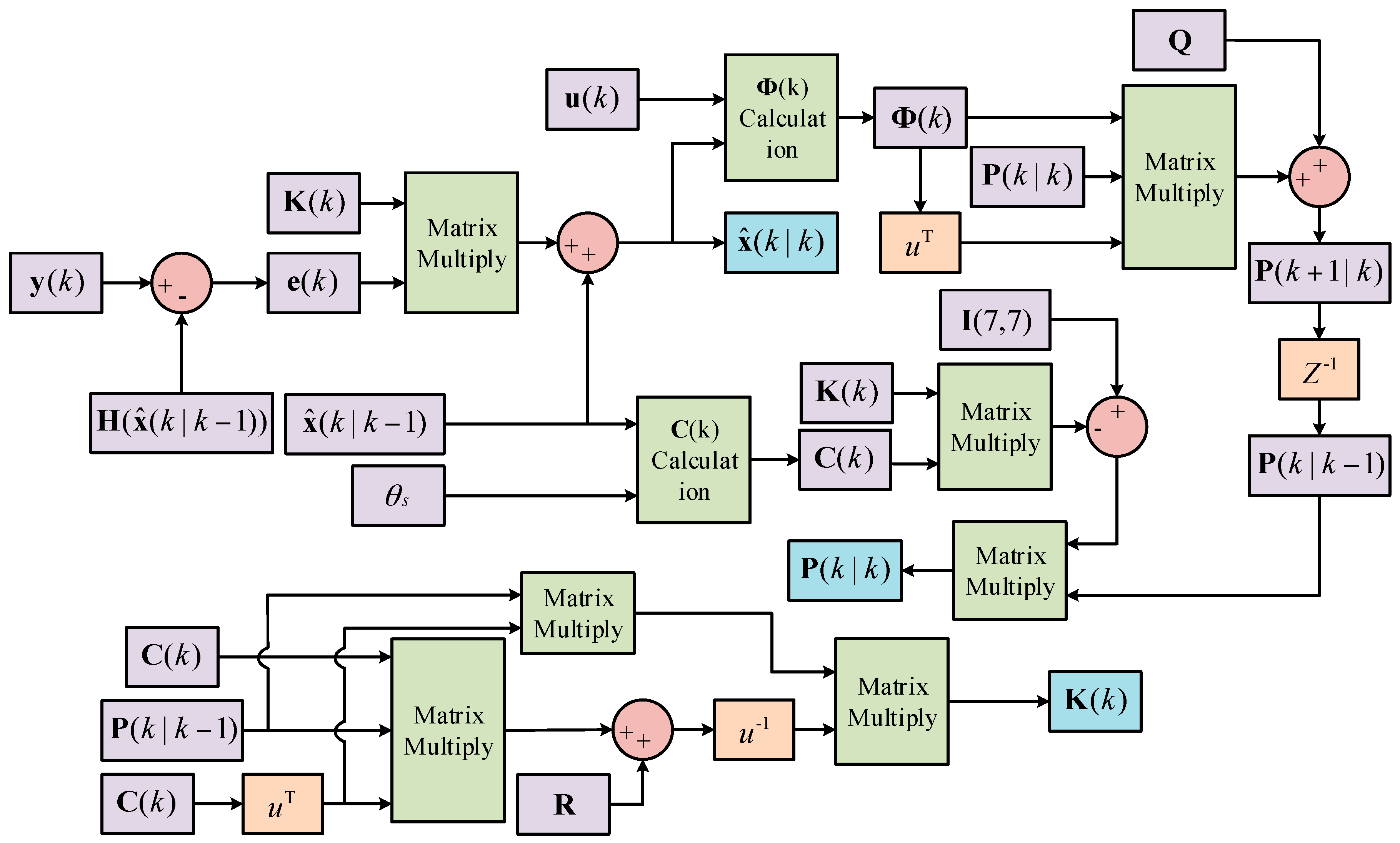
By directly taking the uncertainties in the stochastic process into account and calculating the Kalman gain matrix
K(
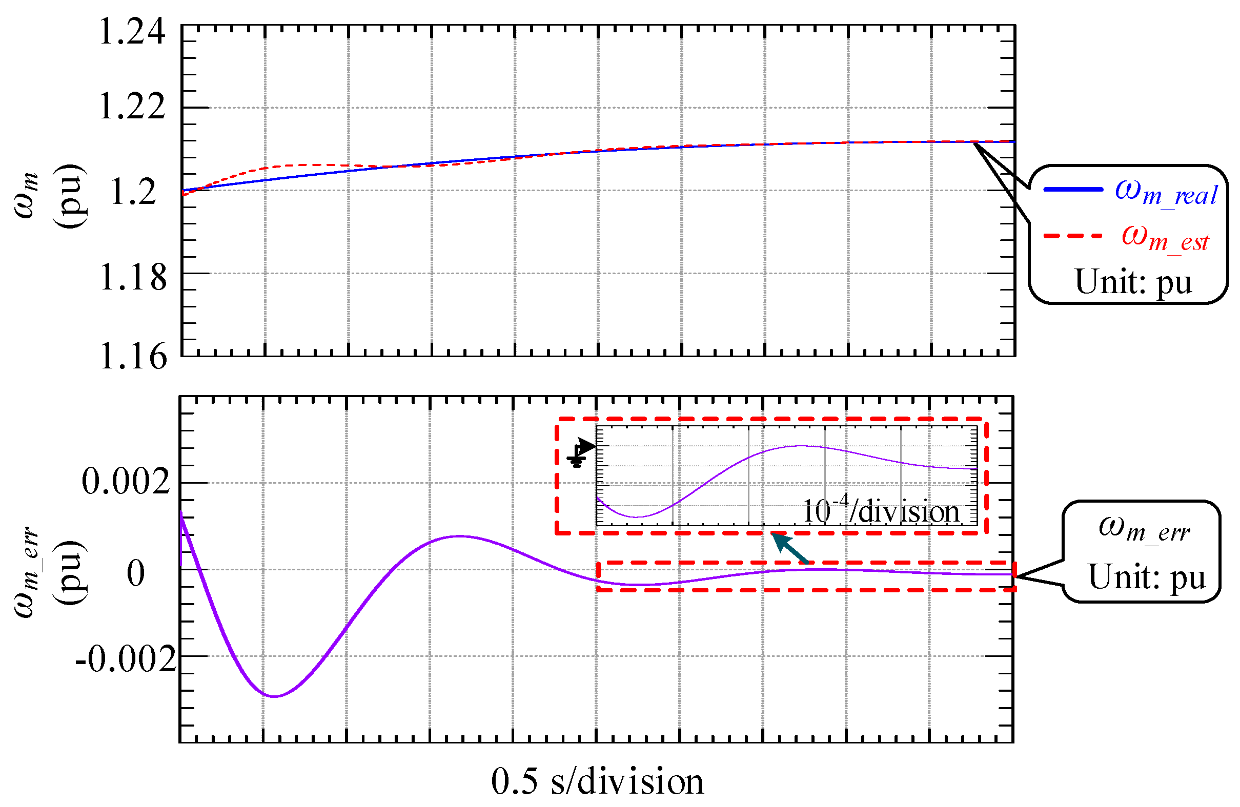
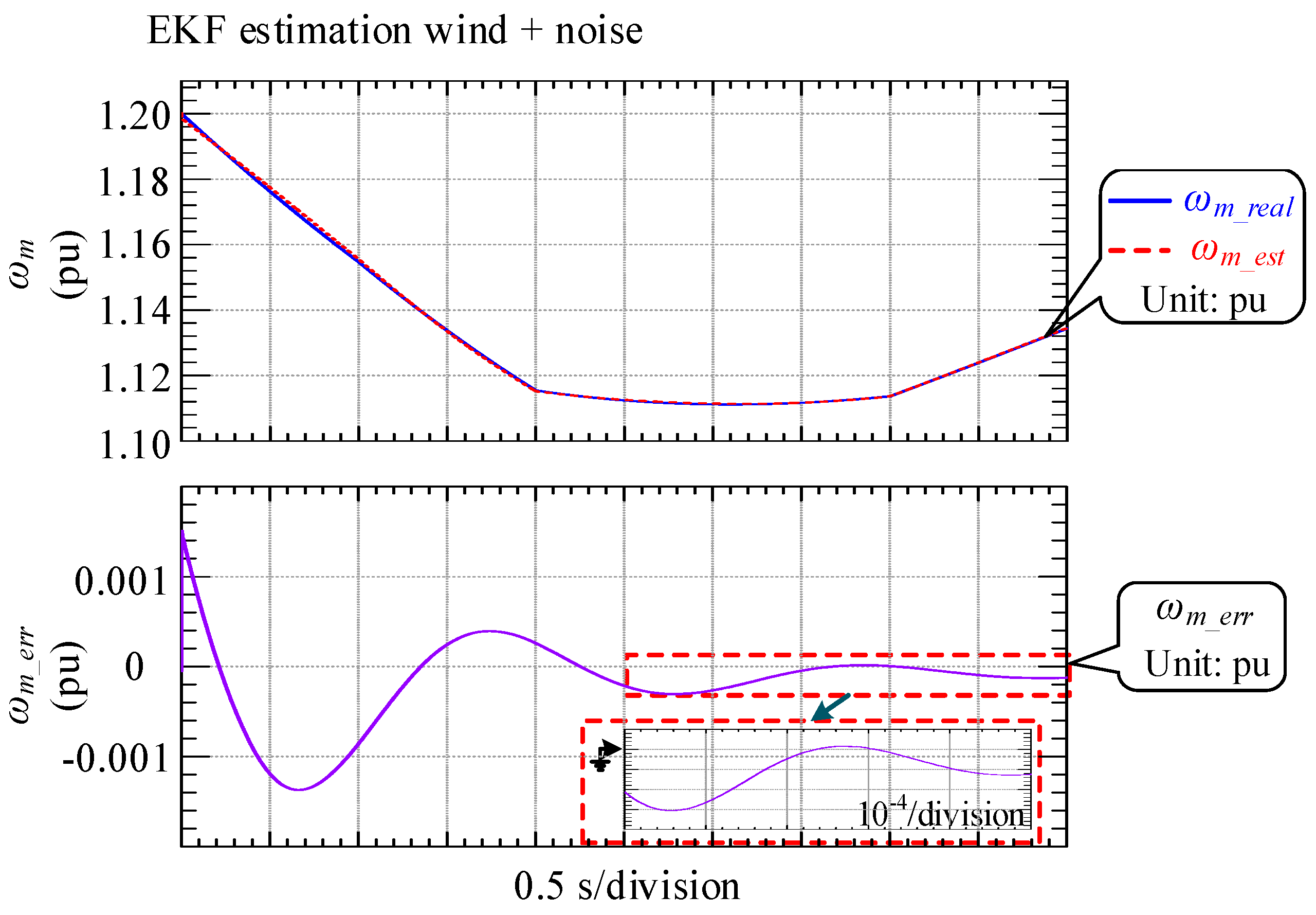
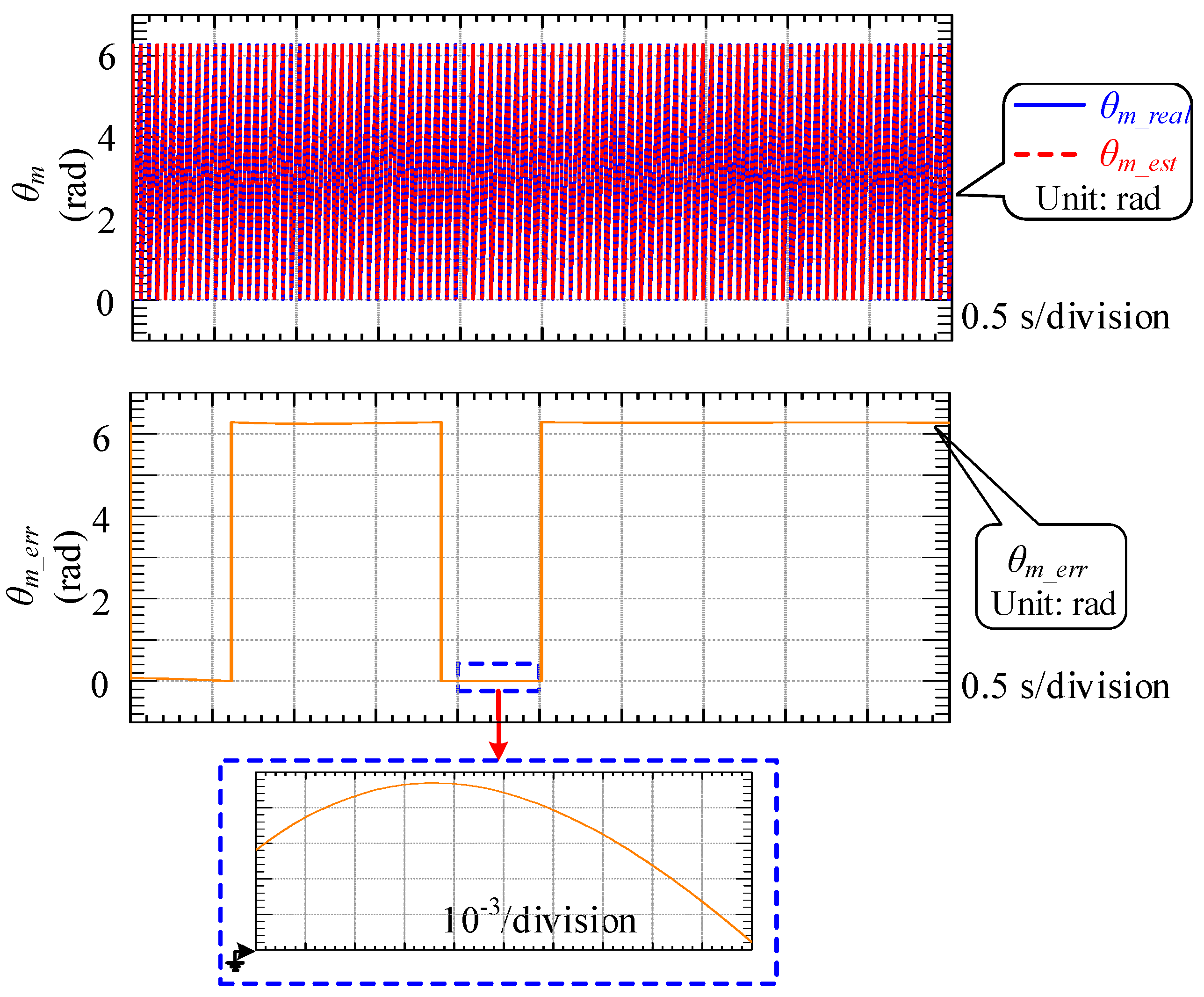
k) online to minimize the errors, the unmeasured state variables can be precisely estimated by adopting the EKF algorithm as an estimator in a nonlinear system. In the seventh-order DFIG model, the mechanical variables are to be estimated since only the electrical variables are available as the inputs and measurements. In the proposed sensorless control process, the rotor angular speed
ωm and position
θm are estimated to replace the conventional speed/position encoder. Assuming the wind speed is 15 m/s, the real and estimated rotor angular speeds and positions are respectively depicted in
Figure 9 and
Figure 10, along with the error between the real and estimated values.
From
Figure 9, it can be seen that the error between the real and estimated rotor angular speeds constantly decreases and the estimation precision is extremely high after 2.5 s, where the error is in the order of 10
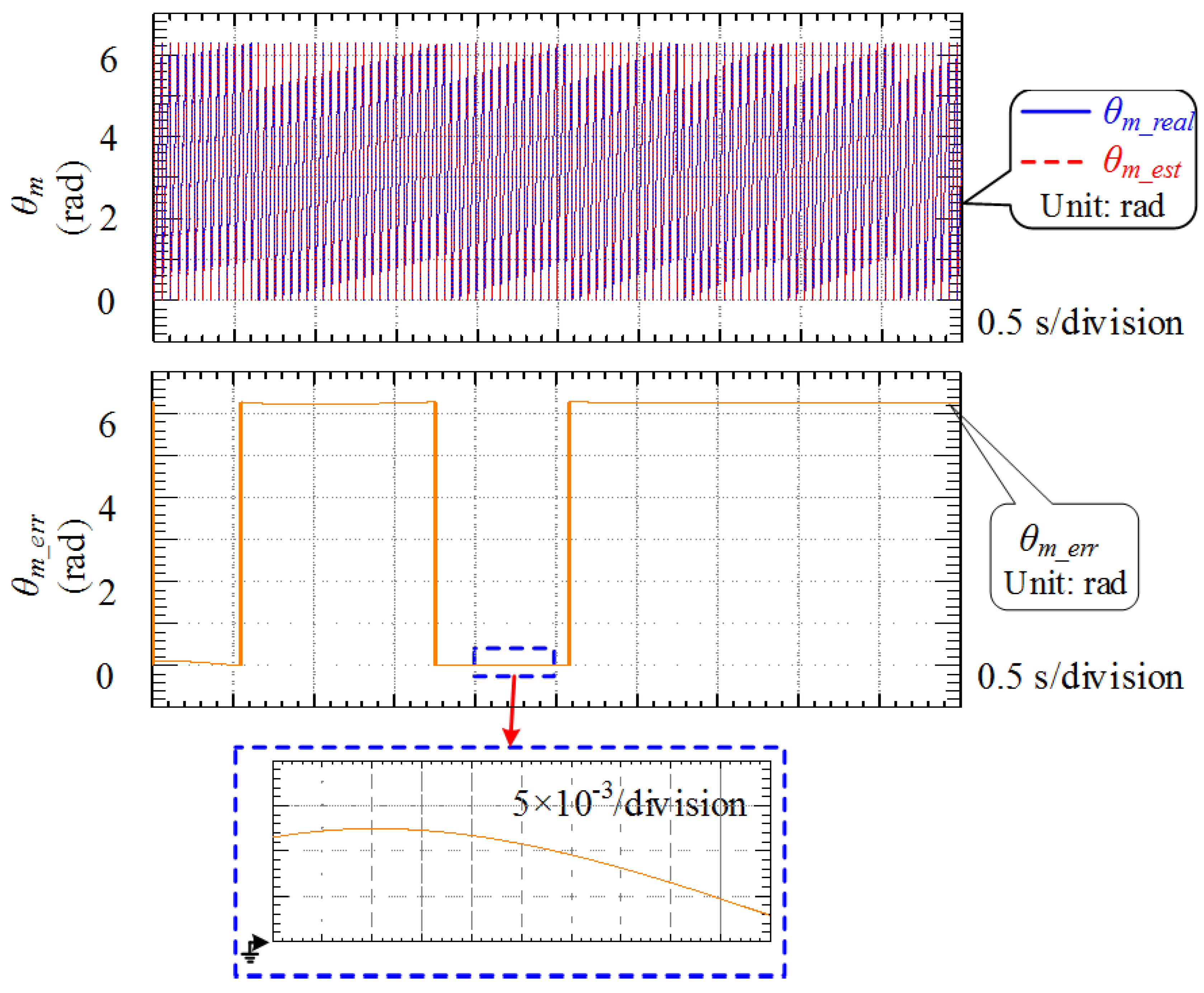
−4 pu. For the estimation of rotor position, which is displayed in
Figure 10, the estimated value tracks the real one very well, and the error is in the order of 5 × 10
−3 rad. Since the rotor angle is limited in the range of [0, 2π], there are some points where the estimation error reaches around 2
π, which is caused by the fact that the estimated value lags the real one by a small time step.
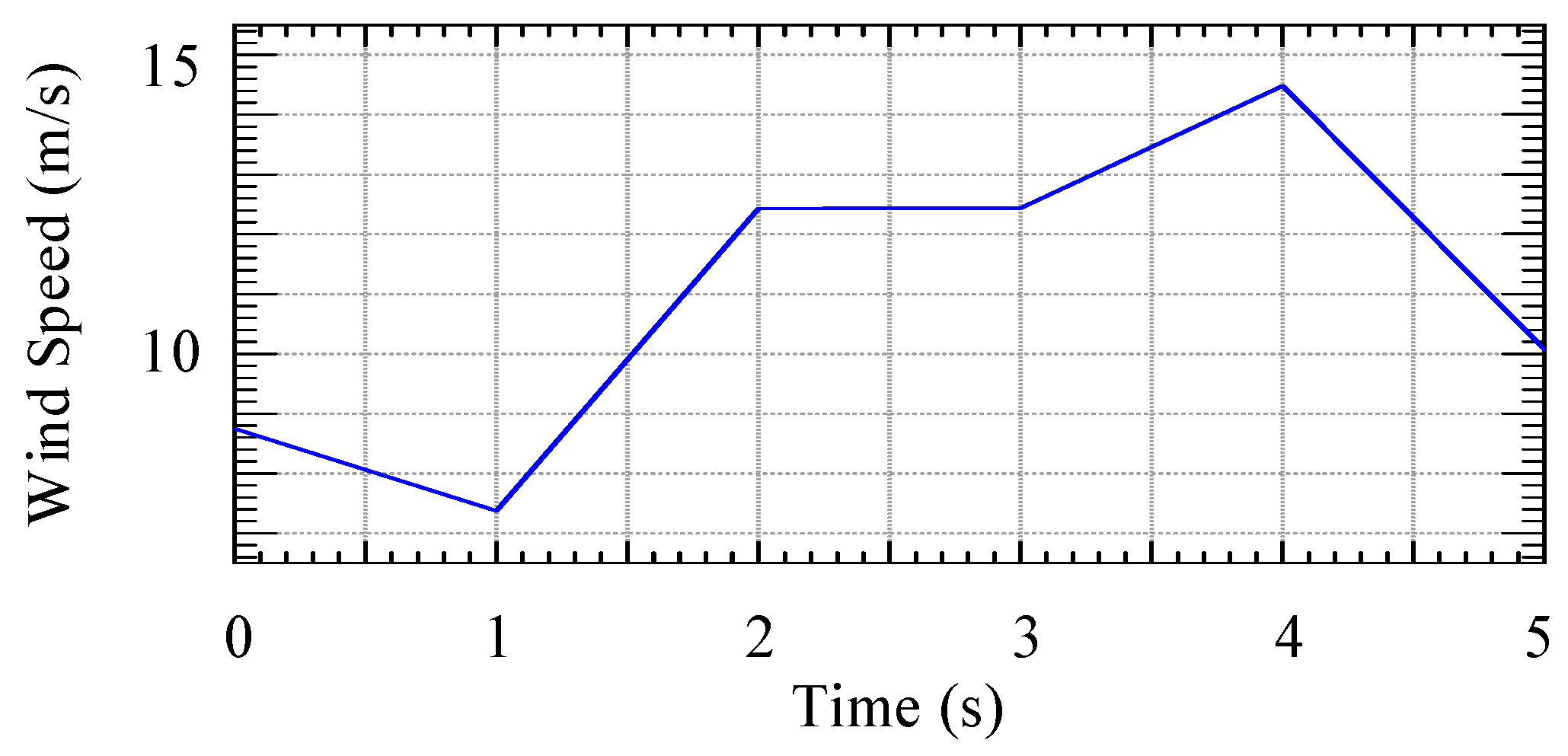
In practice, the wind speed changes from time to time, and the operation of DFIG-WT has to be adjusted so that the highest wind energy conversion efficiency can be derived. The wind speed fluctuation between 7 m/s and 15 m/s is considered to verify that the post-fault DFIG-WT with the proposed hybrid fault-tolerant strategies can stay connected to the grid and continuously provide reliable electrical power output. The wind speed fluctuations are displayed in
Figure 11.
The unique feature of the EKF sensorless control algorithm is that it has strong robustness to the white noises induced in the system modelling process and measurements, which is the reason why it is widely used as an efficient estimator for system state variables regardless of its computational complexity. Along with the wind speed fluctuation between 7 m/s and 15 m/s, the white noises that obey a Gaussian distribution in the measurements are introduced at
t = 0.1 s, with the noise covariance matrix given as
N = [10
−4; 10
−4; 10
−4; 10
−4]
T (unit: pu). The estimation results under this circumstance are displayed in
Figure 12 and
Figure 13, respectively.
By comparing the results derived in
Figure 12 and
Figure 13 with those in
Figure 9 and
Figure 10, the precision of estimation remains at the same level, which fully demonstrates the reliability of the proposed EKF algorithm for sensorless control of DFIG, and the estimated rotor angular speed and position can be directly applied in the overall control process to eliminate the speed/rotor encoder.
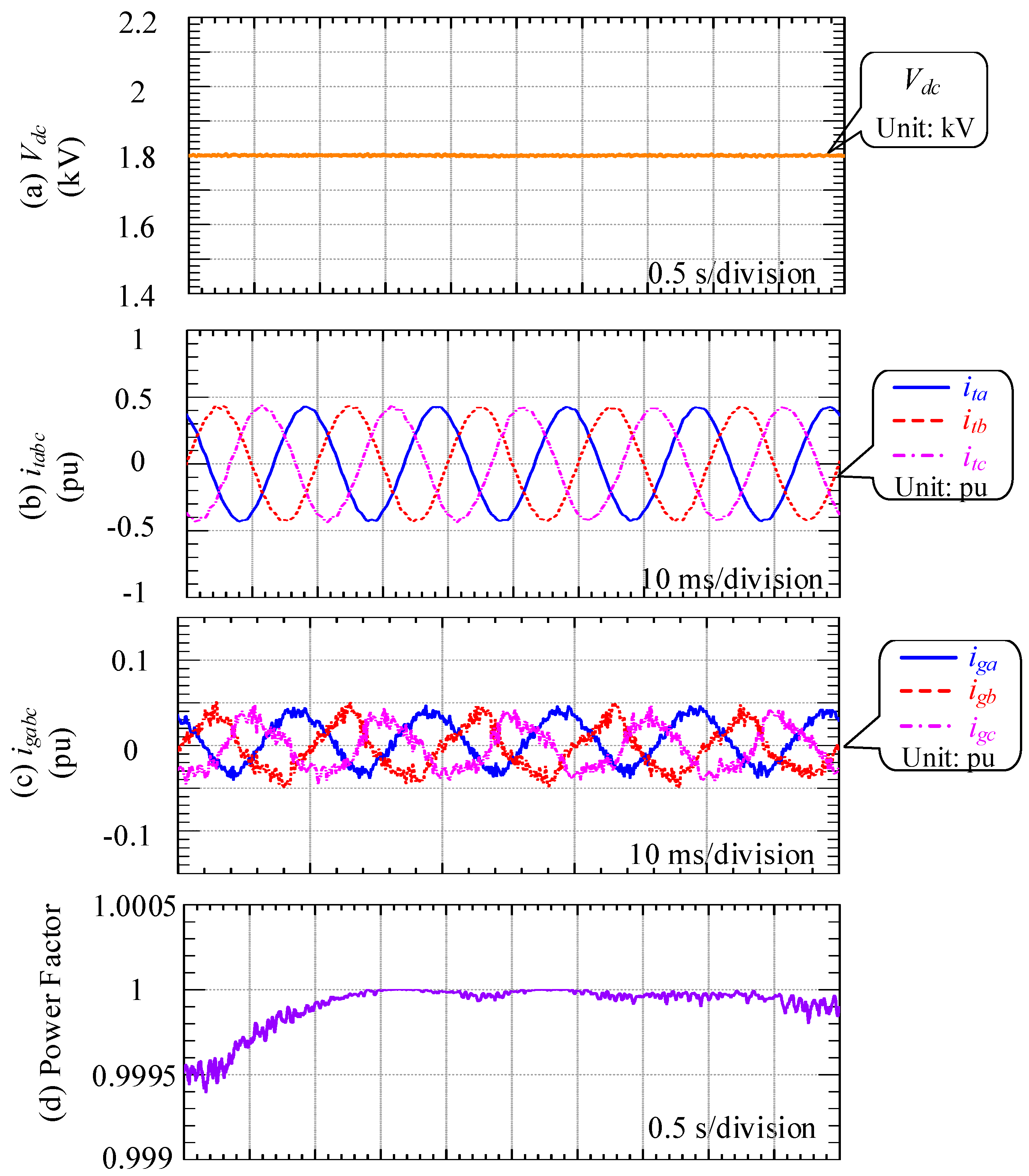
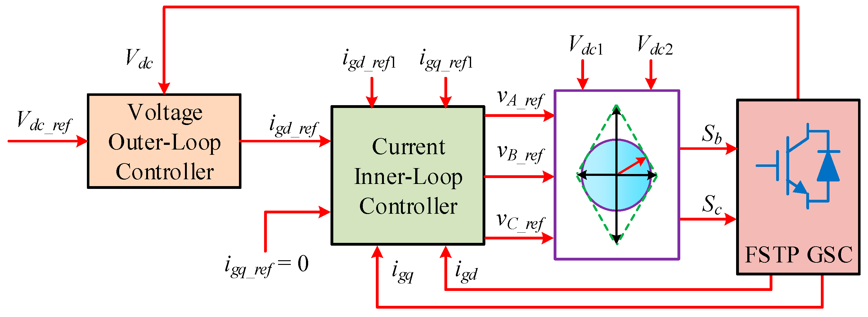
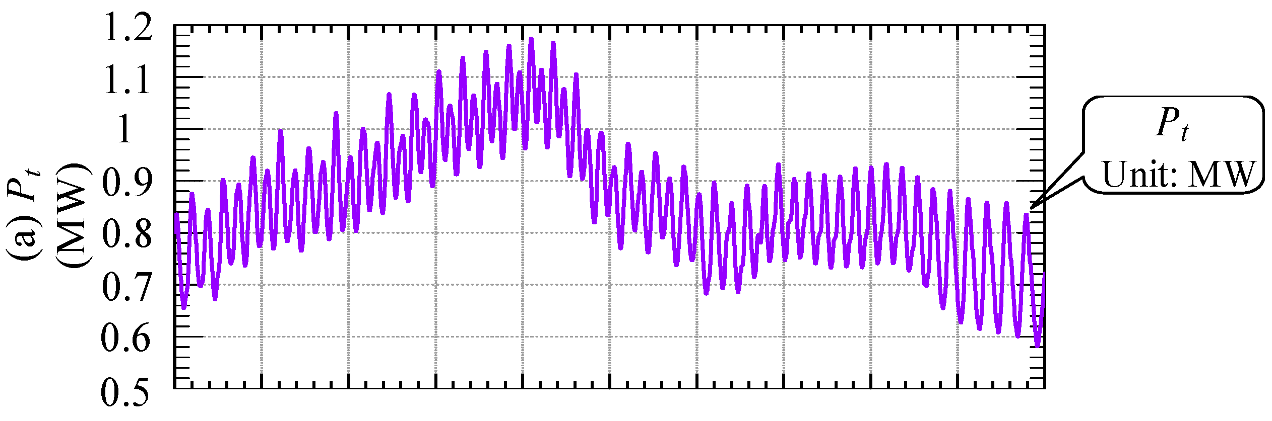
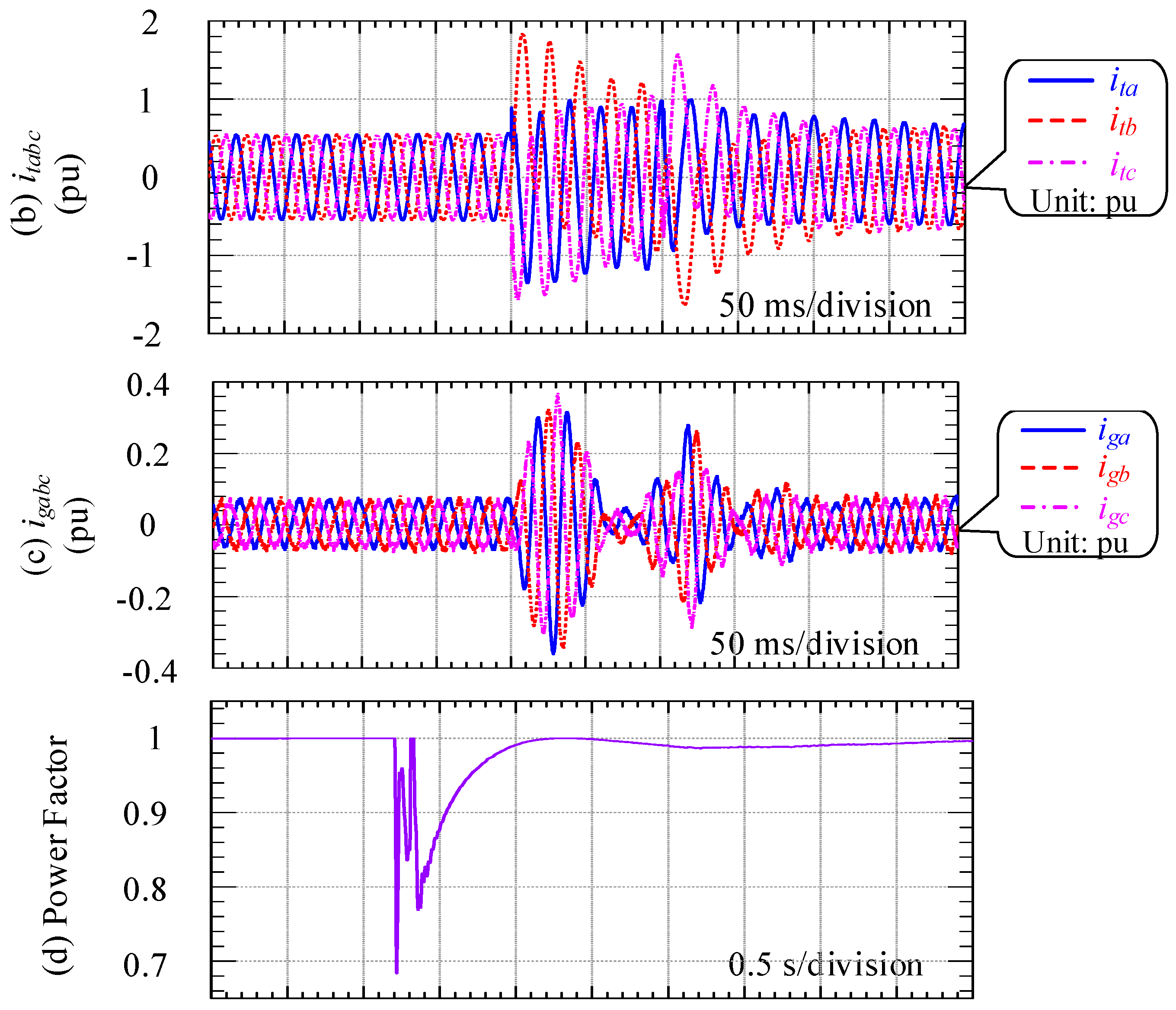
In order to effectively control the DFIG-WT by regulating the active and reactive power through controlling RSC, it is significant that the DC-bus voltage is maintained at an almost fixed value, which is realized in the voltage control process of GSC. Additionally, the harmonic components in the grid-side output three-phase currents should be reduced to ensure the high quality of power generation. Besides, the output power factor is also controlled to be unity. By using FSTP GSC in the post-fault operation, the aforementioned targets can be met, and the simulation results for the DC-bus voltage
Vdc, three-phase GSC currents
igabc, three-phase total output currents
itabc and the output power factor with wind speed fluctuation are displayed in
Figure 14.
From
Figure 14, it can be seen that the DC-bus voltage is almost maintained at 1.8 kV, which is around two-times the value when an SSTP is used in the normal case. In terms of the quality of three-phase currents, nearly sinusoidal waveforms are presented at the output terminal. Although the distortions in the three-phase GSC currents
igabc are obviously observed, they do not deteriorate the overall quality of the output three-phase currents too much. From
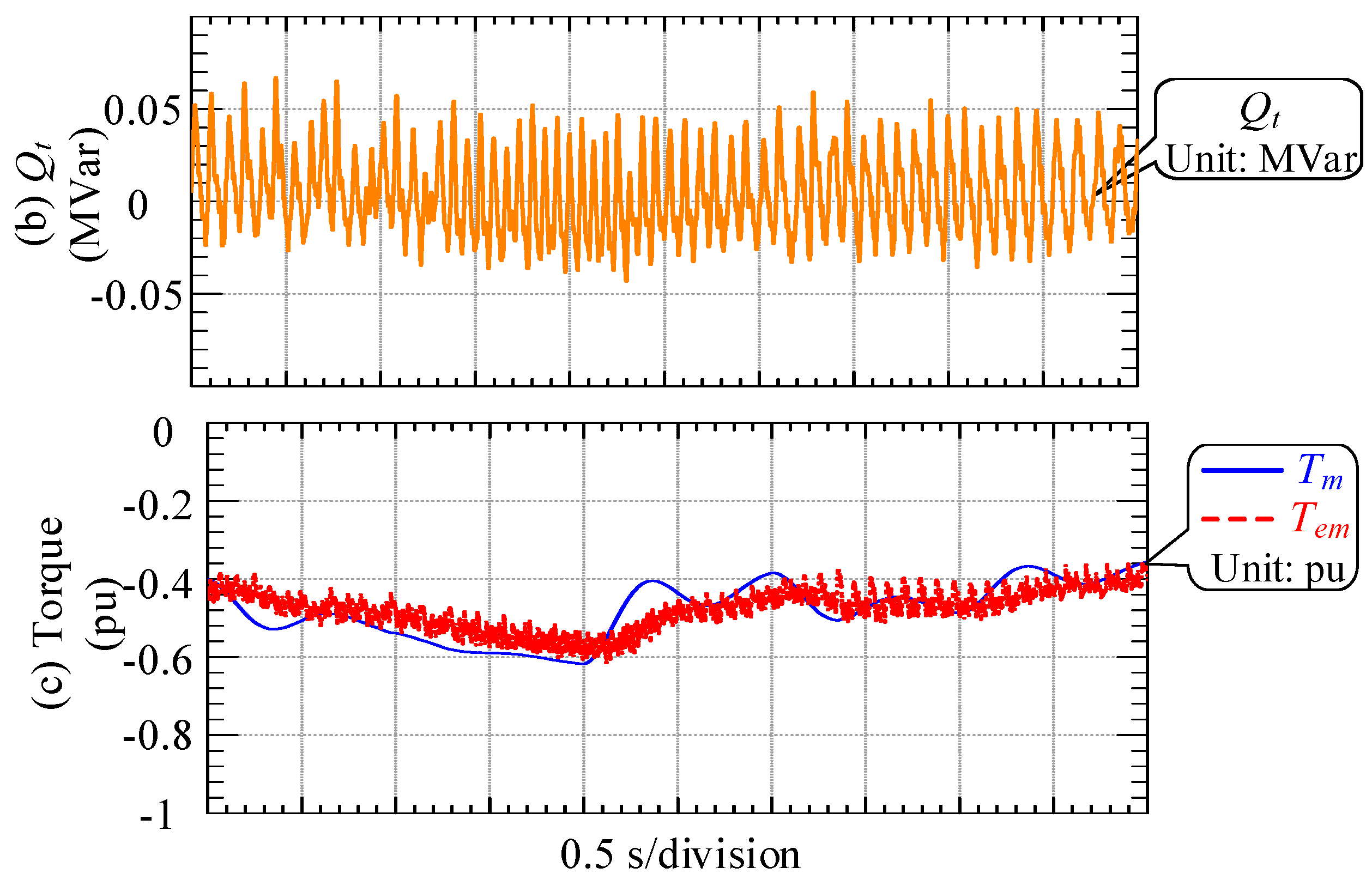
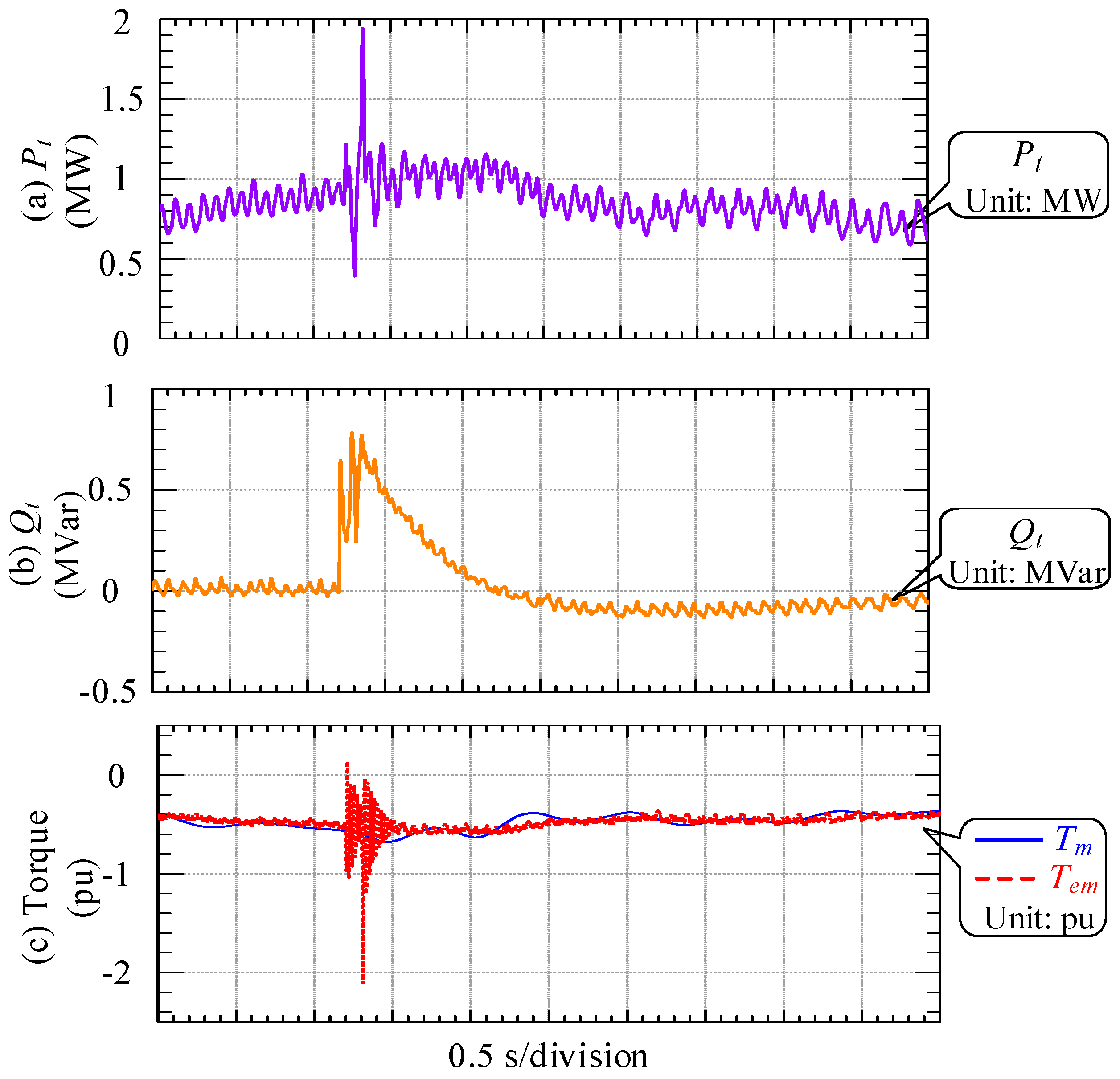
Figure 14d, the output power factor is almost maintained at unity during the whole process, demonstrating relatively good resilience of the FSTP GSC. The performance of the FSTP RSC is illustrated by the total output active and reactive power, and the kinetic characteristic is revealed by the mechanical torque
Tm and electromagnetic torque
Tem. The plots of output power and torque are shown in
Figure 15.
From
Figure 15, the total active power output
Pt changes due to the continuous variations in the mechanical torque. The electromagnetic torque
Tem follows the mechanical torque value to keep the rotor speed constant, as can be seen from
Figure 15c. In addition, appropriate control of the reactive power
Qt is achieved.
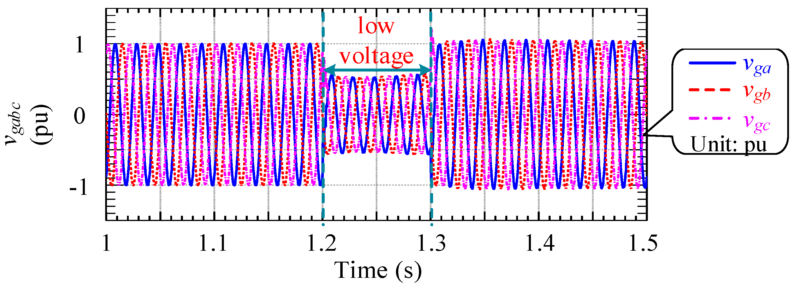
To further demonstrate the validity of the proposed hybrid fault-tolerant strategy with the FSTP BTB converter and the EKF sensorless control algorithm, a three-phase grid voltage sag is applied at
t = 1.2 s, and the three-phase grid voltage amplitude decreases to half of the original value; it ends at
t = 1.3 s. The three-phase grid voltages in this case are displayed in
Figure 16.
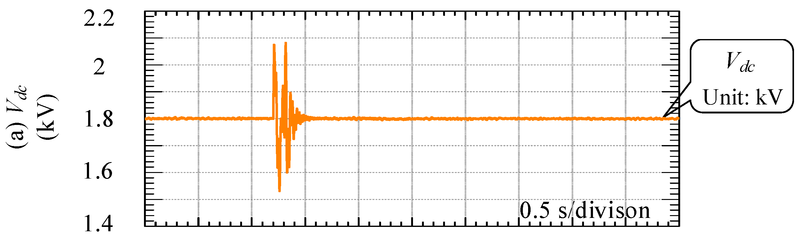
The simulation results with respect to those in
Figure 14 and
Figure 15 by considering the wind speed fluctuation and grid voltage sag are presented in
Figure 17 and
Figure 18, respectively.
From the simulation results shown in
Figure 17 and
Figure 18, some fluctuations in the variables are induced during and after the low voltage period. Especially for the power factor, the lowest value reaches 0.7 at around 1.2 s, and the value of the total output reactive power
Qt during the low voltage period is large. However, the proper control of active and reactive power output can still be obtained after 2.5 s, and the power factor returns to unity. Furthermore, the output three-phase current waveforms are almost sinusoidal after the low voltage period, and relatively good current quality for
igabc is derived. More specifically, the total harmonic distortion (THD) of
itabc and that of
igabc are shown in
Table 6.
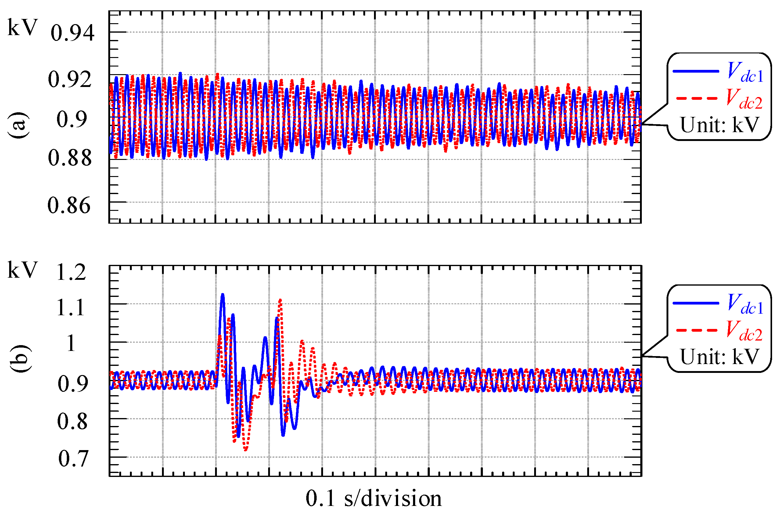
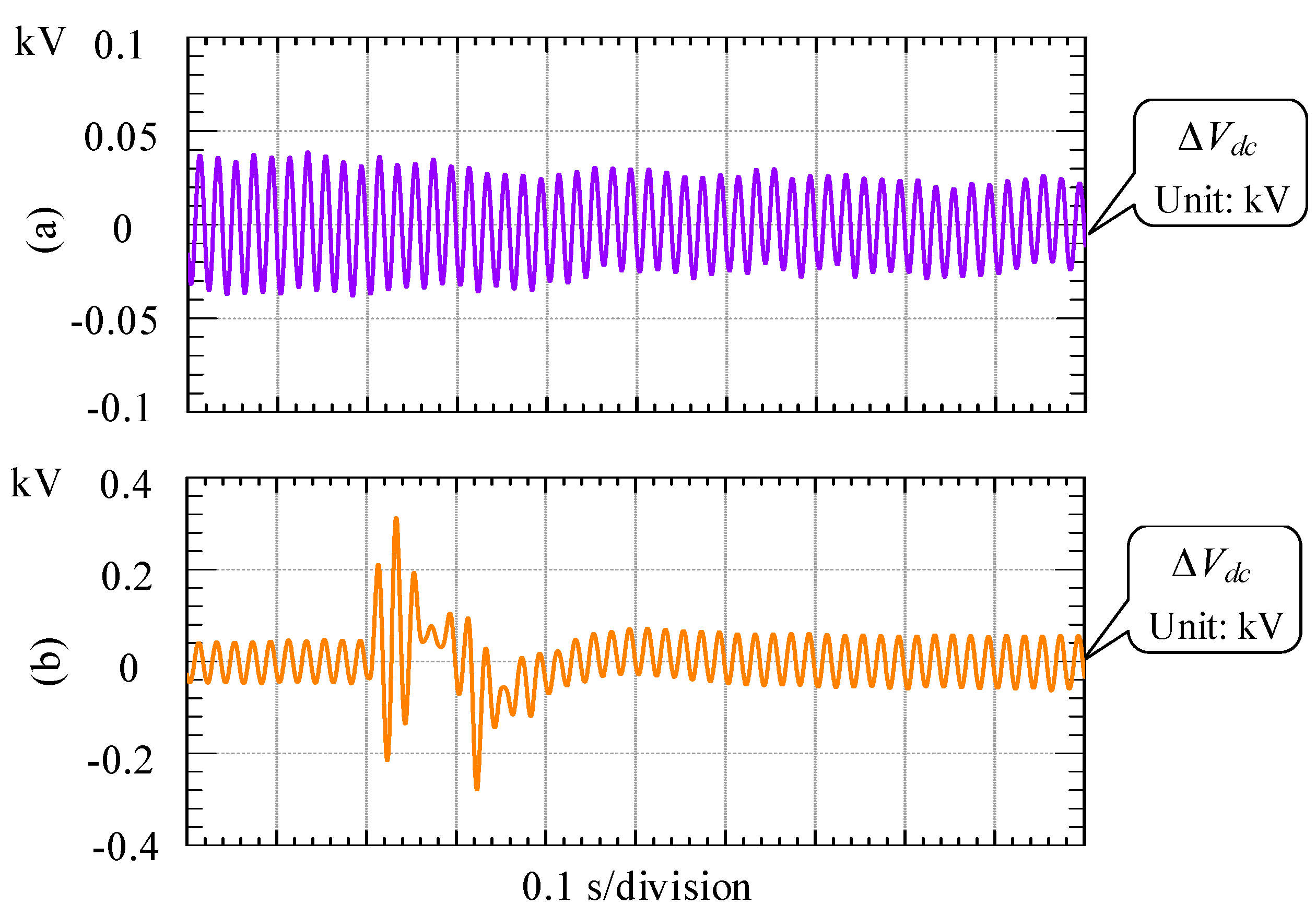
Although the THDs in the three-phase GSC currents are relatively large, the overall quality of the three-phase output currents is not affected greatly, and there is little distortion in the current of each phase. Therefore, with wind speed fluctuation and grid voltage sag, the FSTP GSC can still work properly to keep high-quality power output. Moreover, the balance between the upper and lower DC-link capacitor voltages can be achieved by using the proposed voltage balancing scheme, which maximizes the DC-bus voltage utilization rate. The upper and lower capacitor voltages with and without the low voltage period are displayed in
Figure 19, and the voltage difference is illustrated in
Figure 20 for each case.
It can be seen from
Figure 19 and
Figure 19 that the steady-state error between
Vdc1 and
Vdc2 is small either for the case with or without the low voltage period inserted. From
Figure 19b and
Figure 20b, the fluctuations in the capacitor voltages and the difference are large during the low voltage period, while the voltage values return to the normal level instantly after the grid voltage sag is removed. For both situations, the voltage deviation between
Vdc1 and
Vdc2 is generally within 40 V, which verifies the effectiveness of the voltage balancing scheme.


