Biophysical Micromixer


Abstract
:1. Introduction
2. Numerical Method
3. Disscussions and Results

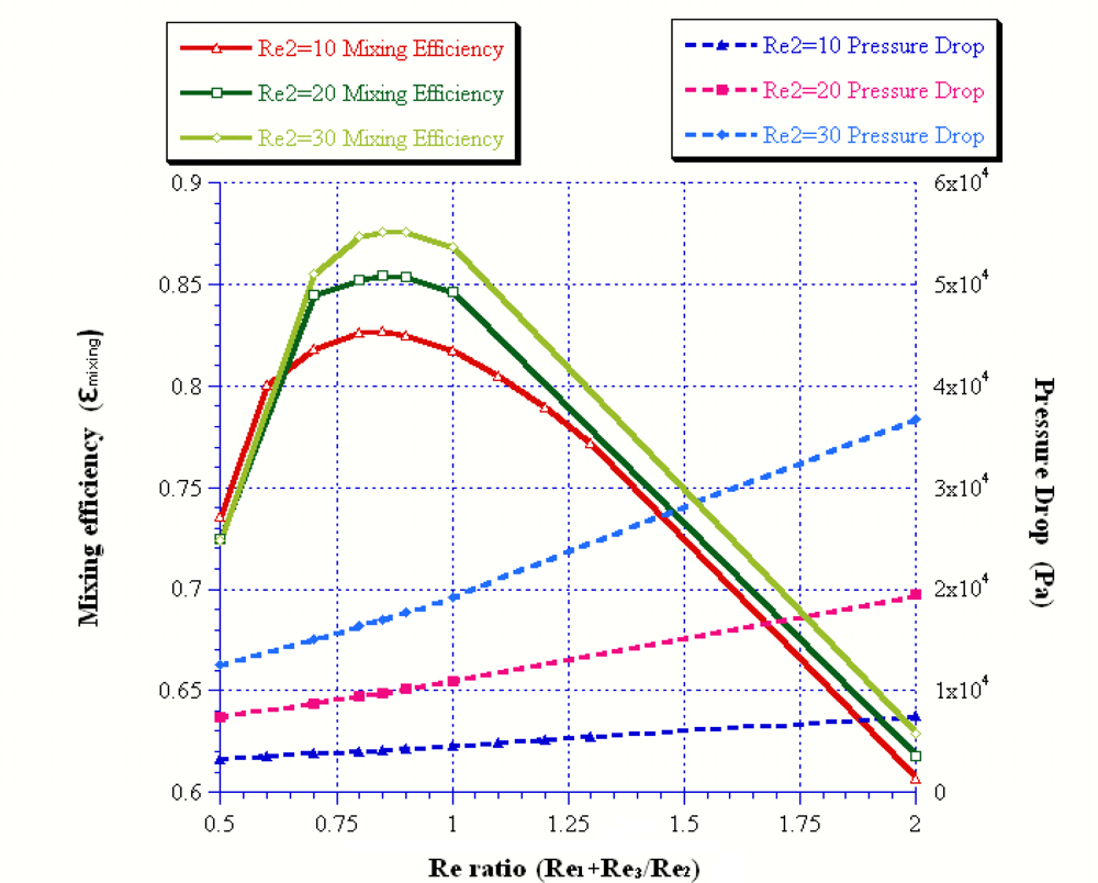
| Rer | 0.5 | 0.85 | 1 | 2 | 1 | |
|---|---|---|---|---|---|---|
| Re1 | 0.5 | 0.85 | 1 | 2 | 10 | |
| Re2 | 1 | 1 | 1 | 1 | 10 | |
| ΔP | AR = 0.5 | 1890.52 | 2333.07 | 2522.87 | 3790.44 | 25999.58 |
| ΔP | AR = 1 | 746.72 | 922.50 | 1891.34 | 1503.66 | 10908.40 |
| ΔP | AR = 2 | 449.06 | 555.37 | 601.07 | 908.16 | 6915.66 |
| ΔP | AR = 10 | 320.69 | 396.79 | 429.52 | 649.51 | 4956.02 |
| εmixing | AR = 0.5 | 0.72 | 0.79 | 0.78 | 0.61 | 0.76 |
| εmixing | AR = 1 | 0.73 | 0.79 | 0.78 | 0.59 | 0.80 |
| εmixing | AR = 2 | 0.69 | 0.80 | 0.80 | 0.67 | 0.85 |
| εmixing | AR = 10 | 0.73 | 0.79 | 0.79 | 0.62 | 0.83 |
4. Conclusions
Acknowledgments
References
- Giordano, N.; Cheng, J.T. Microfluid mechanics: progress and opportunities. J. Phys. Condens. Matter 2001, 13, 271–295. [Google Scholar]
- Trung, N.; Nguyen, N.; Wu, Z. Micromixer – A review. J. Micromech. Microeng 2005, 15, 1–16. [Google Scholar]
- Glasgow, I.; Aubry, N. Enhancement of microfluidic mixing using time pulsing. Lab Chip 2003, 3, 114–120. [Google Scholar]
- Ryu, K.S.; Shaikh, K.; Goluch, E.; Fan, Z.; Liu, C. Micro magnetic stir-bar mixer integrated with parylene microfluidic channels. Lab Chip 2004, 4, 608–613. [Google Scholar]
- Yang, Z.; Matsumoto, S.; Goto, H.; Matsumoto, M.; Maeda, R. Ultrasonic micromixer for microfluidic systems. Sens. Actuat. A: Phys 2001, 93, 266–272. [Google Scholar]
- Hessel, V.; Lowe, H. Microchemical engineering: components, plant concepts user acceptance part I. Chem. Eng. Technol 2003, 26, 13–24. [Google Scholar]
- Hessel, V.; Hardt, S.; Lowe, H.; Schonfeld, F. Laminar mixing in different interdigital micromixers: Experimental characterization. Amer. Inst. Chem. Eng 2003, 49, 566–577. [Google Scholar]
- Lob, P.; Pennemann, H.; Hessel, V.; Men, Y. Impact of fluid path geometry and operating parameters on l/l-dispersion in interdigital micromixers. Chem. Eng. Sci 2006, 61, 2959–2967. [Google Scholar]
- Lee, J.; Kwon, S. Mixing efficiency of a multilamination micromixer with consecutive recirculation zones. Chem. Eng. Sci 2009, 64, 1223–1231. [Google Scholar]
- Lee, S.W.; Kim, D.S.; Lee, S.S.; Kwon, T.H. A split and recombination micromixer fabricated in a pdms three-dimensional structure. J. Micromech. Microeng 2006, 16, 1067–1072. [Google Scholar]
- Branebjerg, J.; Gravesen, P.; Krog, J.P.; Nielsen, C.R. Fast Mixing by Lamination. Proceedings of the Ninth Annual International Workshop on Micro Electro Mechanical Systems, San Diego, CA, USA, 1996; pp. 441–446.
- Lin, C.H.; Tsai, C.H.; Fu, L.M. A rapid three dimensional vortex micromixer utilizing self-rotation effects under low reynolds number conditions. J. Micromech. Microeng 2005, 15, 935–943. [Google Scholar]
- Stroock, A.D.; Dertinger, S.K.W.; Ajdari, A.; Mezic, I.; Stone, H.A.; Whitesides, G.M. Chaotic mixer for microchannels. Science 2002, 295, 647–651. [Google Scholar]
- Lee, J.; Kwon, S. Mixing efficiency of a multilamination micromixer with consecutive recirculation zones. Chem. Eng. Sci 2009, 64, 1223–1231. [Google Scholar]
- Liu, R.H.; Stremler, M.A.; Sharp, K.V.; Olson, M.G.; Santiago, J.G.; Adrian, R.J. Passive mixing in a three-dimensional serpentine microchannel. J. Microelectromech. Syst 2000, 9, 190–197. [Google Scholar]
- Kim, D.S.; Lee, S.W.; Kwon, T.H.; Lee, S.S. A barrier embedded chaotic micromixer. J. Micromech. Microeng 2004, 14, 798–805. [Google Scholar]
- Bhagat, A.A.S.; Peterson, E.T.K; Papautsky, I. A passive planar micromixer with obstructions for mixing at low reynolds numbers. J. Micromech. Microeng 2007, 17, 1017–1024. [Google Scholar]
- Lee, S.H.; Kang, H.J.; Choi, B. A study on the novel micromixer with chaotic flows. Microsyst. Technol 2009, 15, 269–277. [Google Scholar]
- Wu, Z.G.; Nguyen, N.T. Convective-diffusive transport in parallel lamination micromixers. Microfluid. Nanofluid 2005, 1, 208–217. [Google Scholar]
- Ducree, J.; Brenner, T.; Haeberle, S.; Glatzel, T.; Zengerle, R. Multilamination of flows in planar networks of rotating microchannels. Microfluid. Nanofluid 2006, 2, 78–84. [Google Scholar]
- Schwesinger, N.; Frank, T.; Wurmus, H. A modular microfluid system with an integrated micromixer. J. Micromech. Microeng 1996, 6, 99–102. [Google Scholar]
- Bessoth, F.G.; de Mello, A.J.; Manz, A. Microstructure for efficient continuous flow mixing. Anal. Commun 1999, 36, 213–215. [Google Scholar]
- Ehrefeld, W.; Golbig, K.; Hessel, V.; Löwe, H.; Richter, T. Charac-terization of mixing in micromixer by a test reaction: single mixing units and mixer arrays. Ind. Eng. Chem. Res 1999, 38, 1075–1082. [Google Scholar]
- Wong, S.H.; Ward, M.C.L.; Wharton, C.W. Micro T-mixer as a rapid mixing micromixer. Sens. Actuat. B: Chem 2004, 100, 359–379. [Google Scholar]
- Liu, Y.Z.; Kim, B.J.; Sung, H.J. Two-fluid mixing in a microchannel. Int. J. Heat Fluid Fl 2004, 25, 986–995. [Google Scholar]
- Aubin, J.; Fletcher, D.F.; Xuereb, C. Design of micromixers using cfd modeling. Chem. Eng. Sci 2005, 60, 2503–2516. [Google Scholar]
- Paul, C.; Ridha, B.M.; Pierre, S. A Study of Passive Microfluidic Mixers. Proceedings of International Conference on MEMS, NANO and Smart Systems, Banff, AB, Canada, August 2004; IEEE Computer Society: Washington, DC, USA, 2004; pp. 287–293. [Google Scholar]
- Wong, S.H.; Bryant, P.; Ward, M.; Wharton, C. Investigation of mixing in a cross-shaped micromixer with static mixing elements for reaction kinetics studies sens. Sens. Actuat. B: Chem 2003, 95, 414–424. [Google Scholar]
- Wang, C.T.; Huang, R.Y. Study of proton exchange membrane fuel cell flow slab design. Chung Cheng Inst. Technol 2009. (In Press). [Google Scholar]


| Reoutlet | 45 | 54 | 57 | 60 | 90 |
|---|---|---|---|---|---|
| Pe | 40215.7 | 48258.84 | 50941.22 | 53620.92 | 80431.38 |
| Sc | 893.68 | 893.68 | 893.68 | 893.68 | 893.68 |
| Rer = 0.5 | Rer = 0.85 | Rer = 1 | Rer = 2 | |||||
|---|---|---|---|---|---|---|---|---|
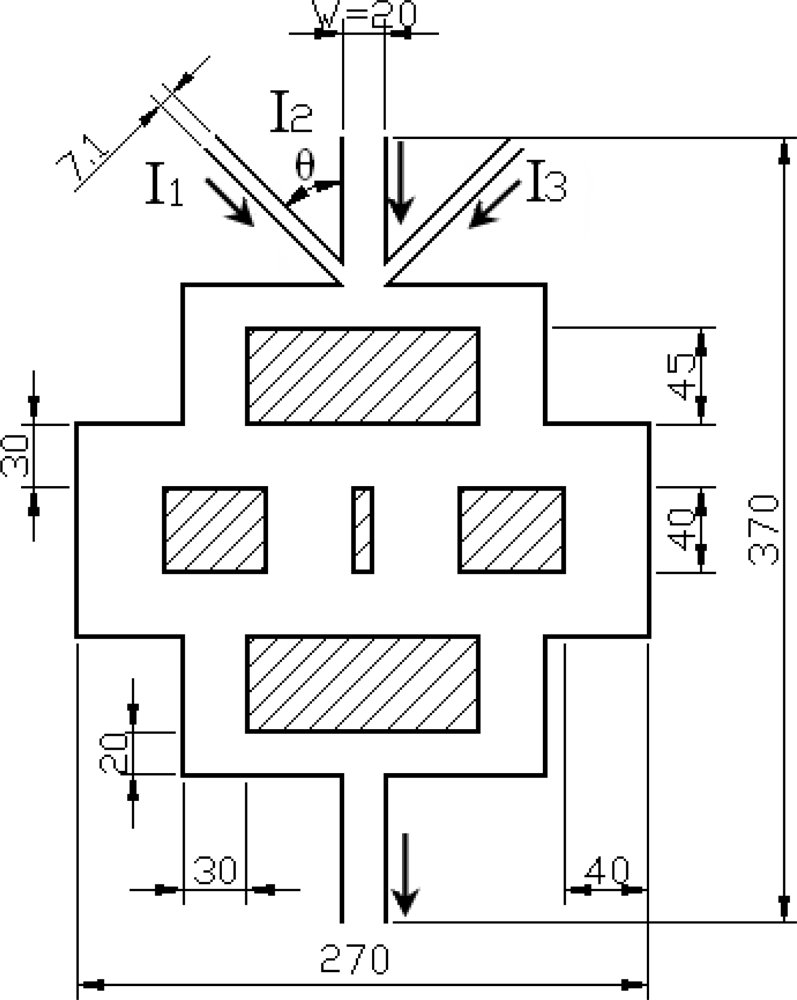
| Inlet angle of side channel, θ | εmixing | ΔP | εmixing | ΔP | εmixing | ΔP | εmixing | ΔP |
| 90° | 0.737 | 310.901 | 0.786 | 384.537 | 0.771 | 417.240 | 0.581 | 632.116 |
| 60° | 0.738 | 300.758 | 0.791 | 371.628 | 0.776 | 403.076 | 0.580 | 609.910 |
| 45° | 0.739 | 300.025 | 0.796 | 371.122 | 0.779 | 401.692 | 0.584 | 607.082 |
| 30° | 0.738 | 300.781 | 0.803 | 371.240 | 0.790 | 402.526 | 0.589 | 607.998 |
| 0° | 0.729 | 289.187 | 0.764 | 356.386 | 0.750 | 385.829 | 0.575 | 586.702 |
© 2009 by the authors; licensee MDPI, Basel, Switzerland This article is an open access article distributed under the terms and conditions of the Creative Commons Attribution license (http://creativecommons.org/licenses/by/3.0/).
Share and Cite
Wang, C.-T.; Hu, Y.-C.; Hu, T.-Y. Biophysical Micromixer. Sensors 2009, 9, 5379-5389. https://doi.org/10.3390/s90705379
Wang C-T, Hu Y-C, Hu T-Y. Biophysical Micromixer. Sensors. 2009; 9(7):5379-5389. https://doi.org/10.3390/s90705379
Chicago/Turabian StyleWang, Chin-Tsan, Yuh-Chung Hu, and Tzu-Yang Hu. 2009. "Biophysical Micromixer" Sensors 9, no. 7: 5379-5389. https://doi.org/10.3390/s90705379