A High Isolation Series-Shunt RF MEMS Switch


Abstract
:1. Introduction
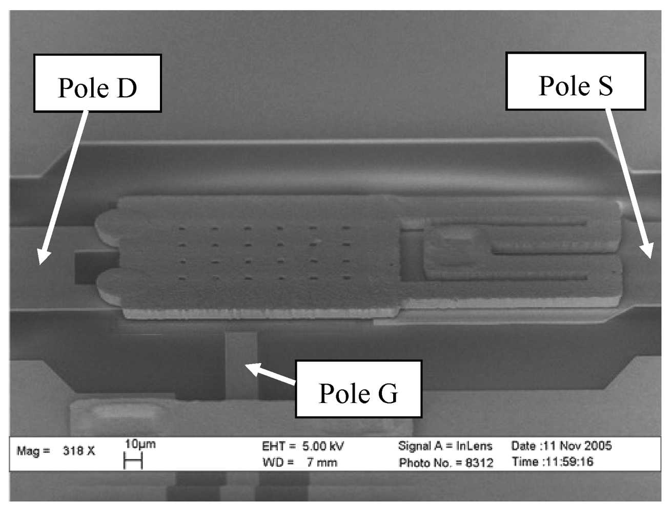
2. 3-Port MEMS Switch
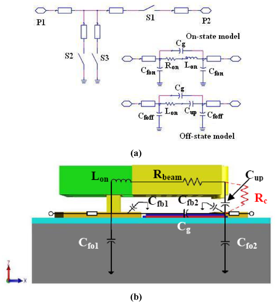
3. Series-shunt MEMS Switch
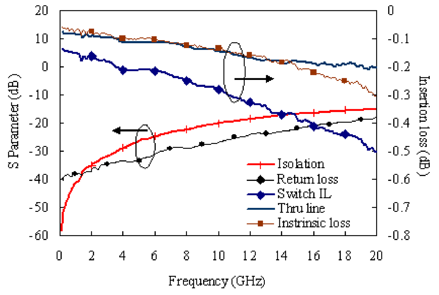
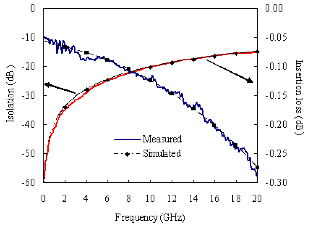
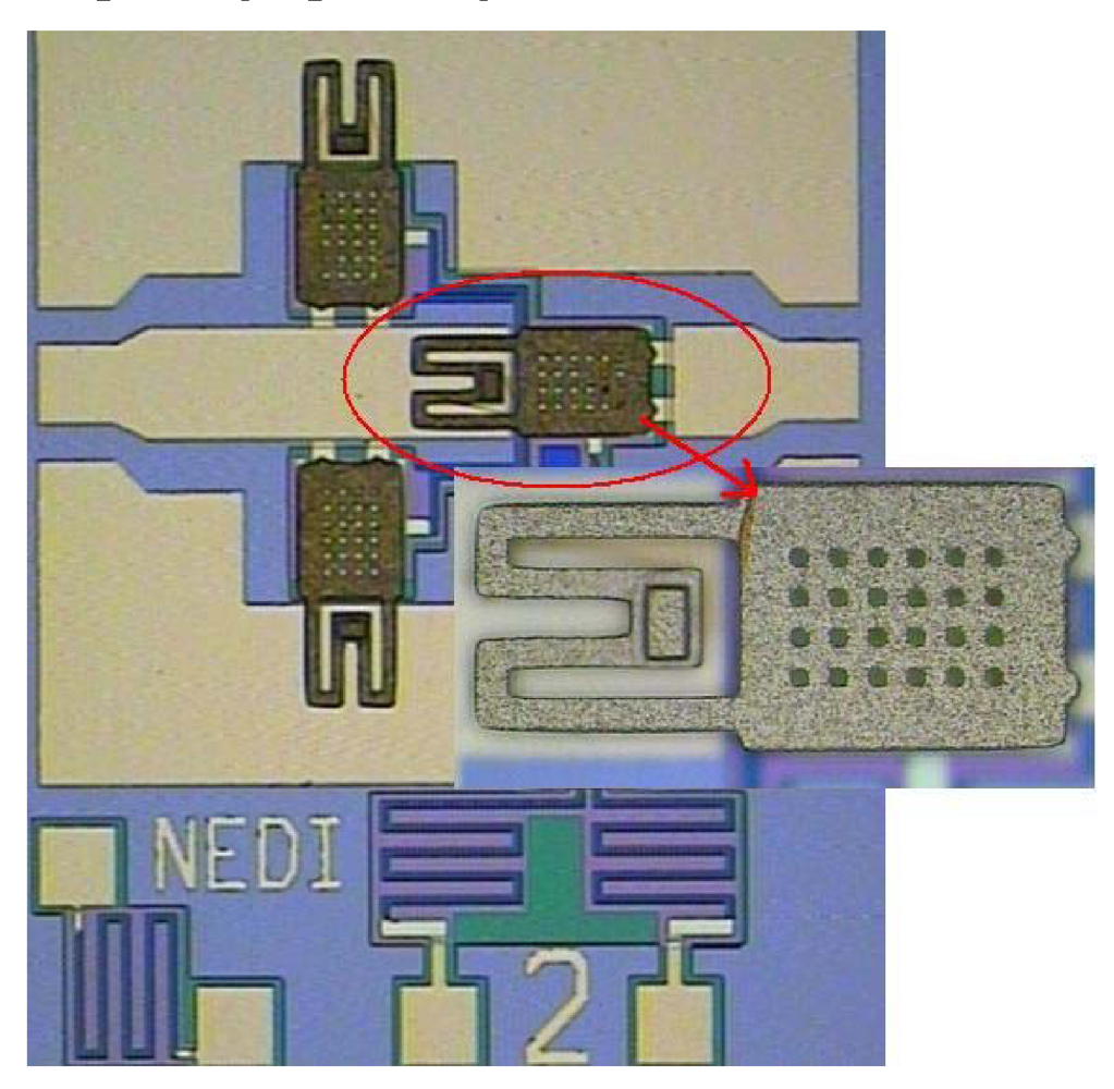
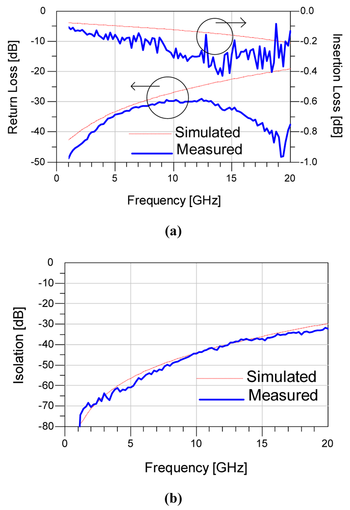
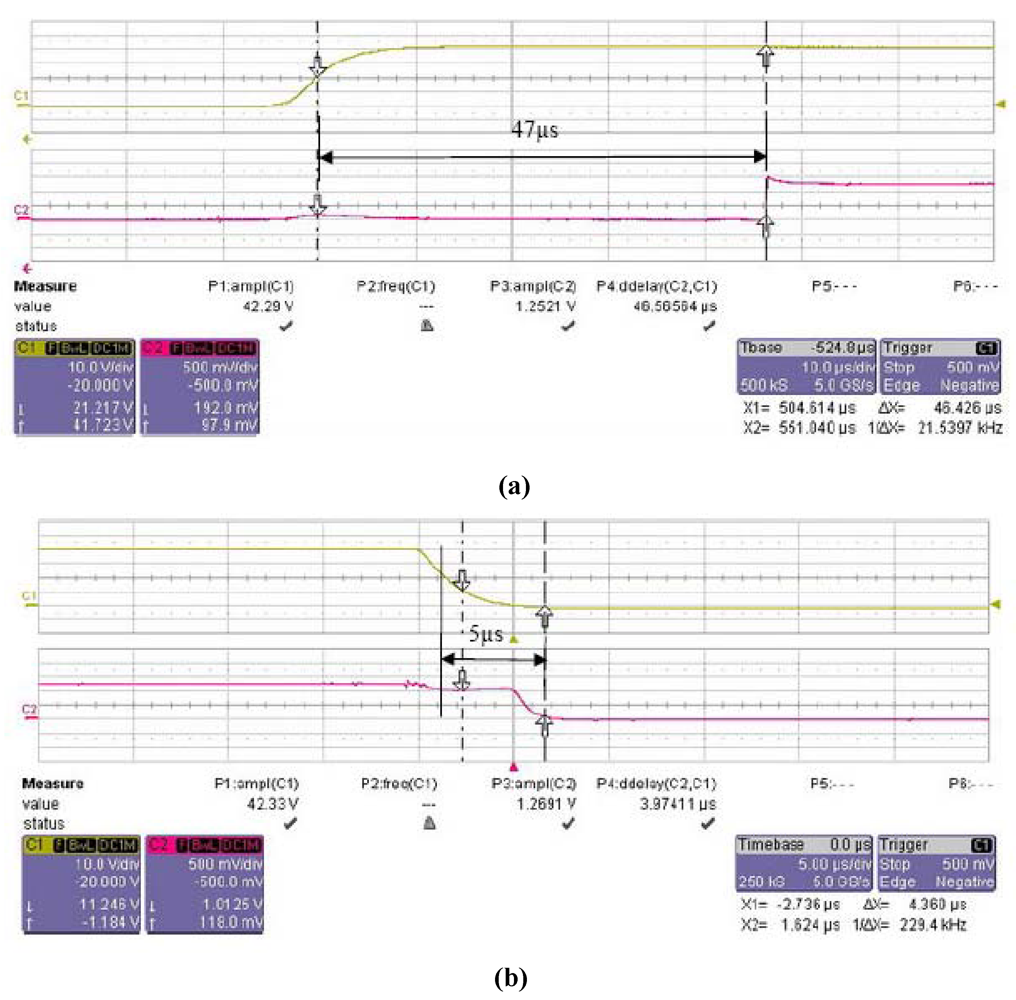
4. Fabrication and Results
5. Conclusions
Acknowledgments
References and Notes
- Rebeiz, G.M.; Muldavin, J.B. RF MEMS switches and switch circuits. IEEE Microw. Mag. 2001, 2, 59–71. [Google Scholar]
- Majumder, S.; Lampen, J.; Morrison, R.; Maciel, J. A packaged, high-lifetime ohmic MEMS RF switch. IEEE MTT-S Int. Microwave Symp. Dig. 2003, 3, 1935–1938. [Google Scholar]
- Nishijima, N.; Hung, J.; Rebeiz, G.M. A low-voltage high contact force RF-MEMS switch. IEEE MTT-S Int. Microwave Symp. Dig. 2004, 2, 577–580. [Google Scholar]
- Zhu, J.; Zhou, B.L.; Yu, Y.W. DC-contact RF MEMS switches with bias physically insulated from RF signal. Proceedings of IEEE International Conference on Solid-State and Integrated-Circuit Tech, Beijing, China, October 2004; pp. 1699–1702.
- Lee, J.; Yang, W.S.; Kang, S.; Choi, C.A. Design and parameter-extraction based small-signal modeling of a novel center-anchor MEMS series switch. Proceedings of the 34th European Microwave Conference, Amsterdam, The Netherlands, October 2004; pp. 1433–1436.
- Mihailovich, R.E.; Kim, M.; Hacker, J.B. MEM relay for reconfigurable RF circuits. IEEE Microw. Wirel. Compon. Lett. 2001, 11, 53–55. [Google Scholar]
- Yu, Y.W.; Jia, S.X.; Zhu, J.; Chen, C. A broadband ohmic RF MEMS switch. Chi. J. Sens. Actuat. 2008, 21, 688–691. [Google Scholar]
- Muldavin, J.B.; Rebeiz, G.M. High isolation CPW MEMS shunt switches, Part 2: design. IEEE Trans. Microwave Theory 2000, 48, 1053–1056. [Google Scholar]
- Rebeiz, G.M. RF MEMS: Theory, Design, and Technology; John Wiley & Sons: Hoboken, NJ, USA, 2003; pp. 239–256. [Google Scholar]
- Tan, G.L.; Rebeiz, G.M. DC-26GHz MEMS series-shunt absorptive switches. IEEE MTT-S Int. Microwave Symp. Dig. 2001, 1, 325–328. [Google Scholar]
- Muldavin, J.; Bozler, C.; Keast, C. Wafer-scale packaged RF-MEMS switches. IEEE MTT-S Int. Microwave Symp. Dig. 2006, 267–270. [Google Scholar]
- De Los Santors, H.J.; Rassoulian, S.; Maciel, J. MEMS for future microwave systems. IEEE MTT-S Int. Microwave Symp. Dig. 2005, 905–908. [Google Scholar]
- Renes, I.C.; Goldsmith, C.L.; Nordquist, C.D. A low loss RF MEMS Ku-band integrated switched filter bank. IEEE Microw. Wirel. Compon. Lett. 2005, 15, 74–76. [Google Scholar]
- Huang, J.-M.; Liew, K.M.; Wong, C.H. Mechanical design and optimization of capacitive micromachined switch. Sens. Actuat. A-Phys. 2001, 93, 273–285. [Google Scholar]
- Lee, J.; Je, C.H.; Kang, S.; Choi, C.A. A low-loss single-pole six-throw switch based on compact RF MEMS switches. IEEE Trans. Microwave Theory 2005, 53, 3335–3344. [Google Scholar]


| Properties | Simulated and calculated results |
|---|---|
| Resonant frequency, f0 (KHz) | 8.599338 |
| Generalized mass, m (ng) | 0.8118015 |
| Pull-in voltage, VP (V) | 19.5 |
| Spring constant, k (N/m) | 2.37 |
| Reaction force, Fr (μN) | ≈ 7 |
| Switch time, ton (μs) | 48.5 |
| Parameters | Extracted values |
|---|---|
| Ron (Ω) | 0.6 |
| Lon (pH) | 195 |
| Cup (fF) | 6.4 |
| Cg (fF) | 10 |
| Cfon (fF) | 8 |
| Cfoff (fF) | 10 |
© 2009 by the authors; licensee Molecular Diversity Preservation International, Basel, Switzerland. This article is an open access article distributed under the terms and conditions of the Creative Commons Attribution license (http://creativecommons.org/licenses/by/3.0/).
Share and Cite
Yu, Y.-W.; Zhu, J.; Jia, S.-X.; Shi, Y. A High Isolation Series-Shunt RF MEMS Switch. Sensors 2009, 9, 4455-4464. https://doi.org/10.3390/s90604455
Yu Y-W, Zhu J, Jia S-X, Shi Y. A High Isolation Series-Shunt RF MEMS Switch. Sensors. 2009; 9(6):4455-4464. https://doi.org/10.3390/s90604455
Chicago/Turabian StyleYu, Yuan-Wei, Jian Zhu, Shi-Xing Jia, and Yi Shi. 2009. "A High Isolation Series-Shunt RF MEMS Switch" Sensors 9, no. 6: 4455-4464. https://doi.org/10.3390/s90604455