Fully Open-Access Passive Dry Electrodes BIOADC: Open-Electroencephalography (EEG) Re-Invented

 , ,
, , 

Abstract
:1. Introduction
2. Methods
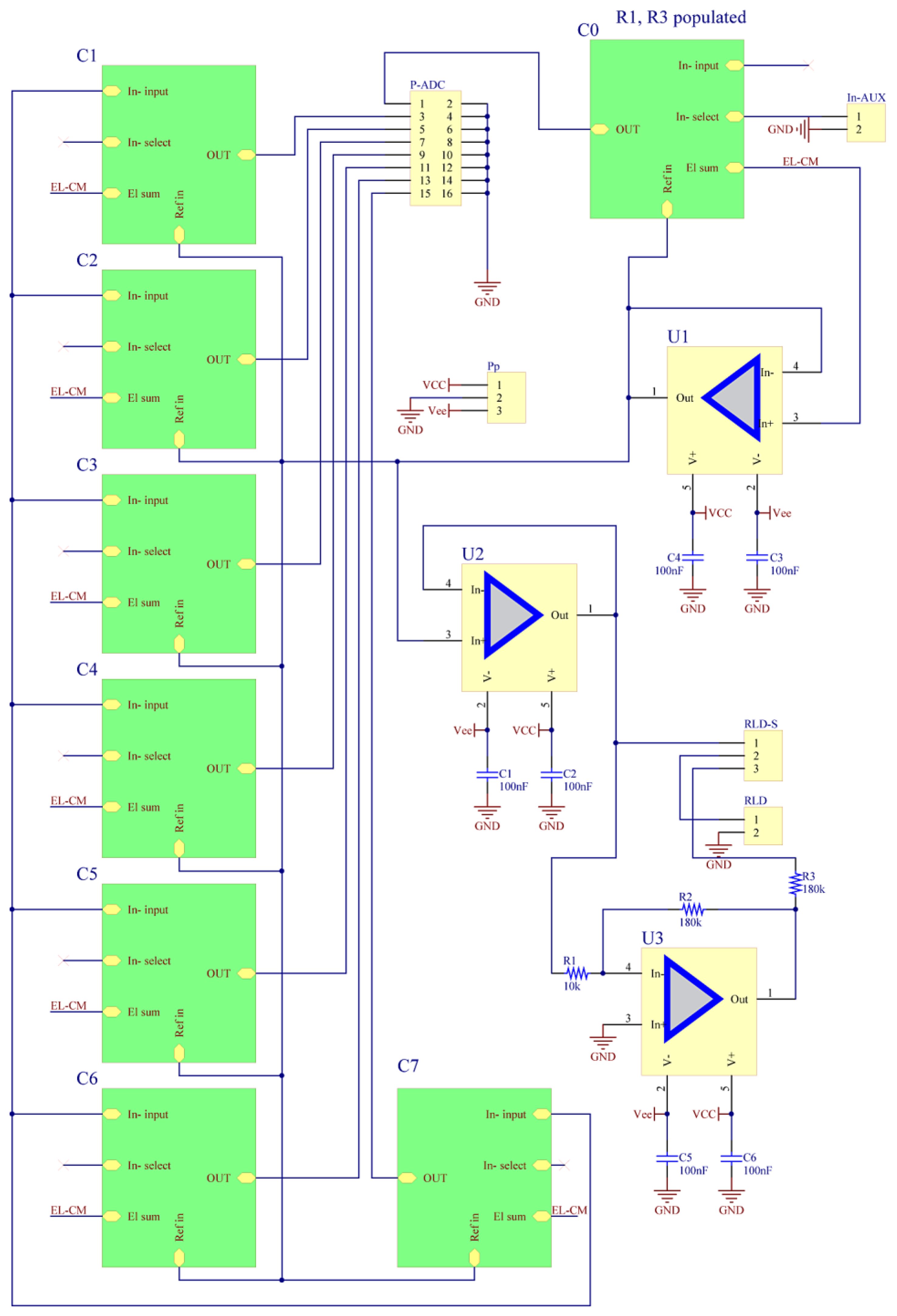
2.1. Analogue Front-End
2.2. BIOADC
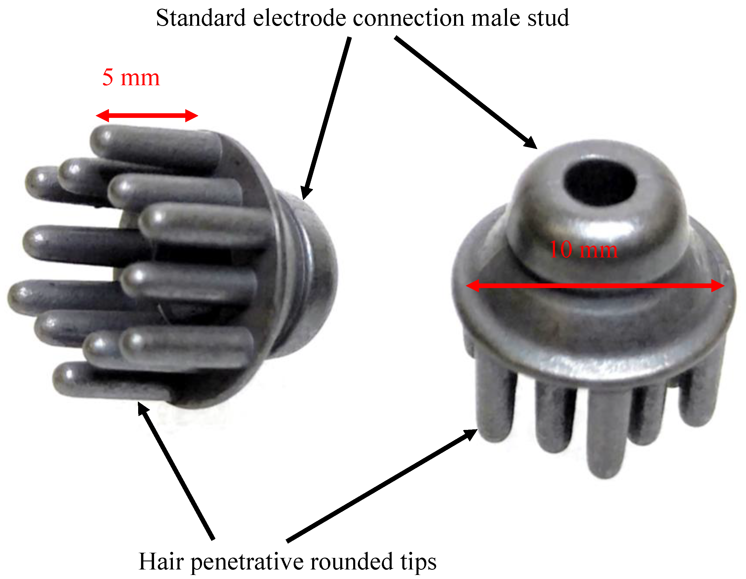
2.3. Dry Electrodes
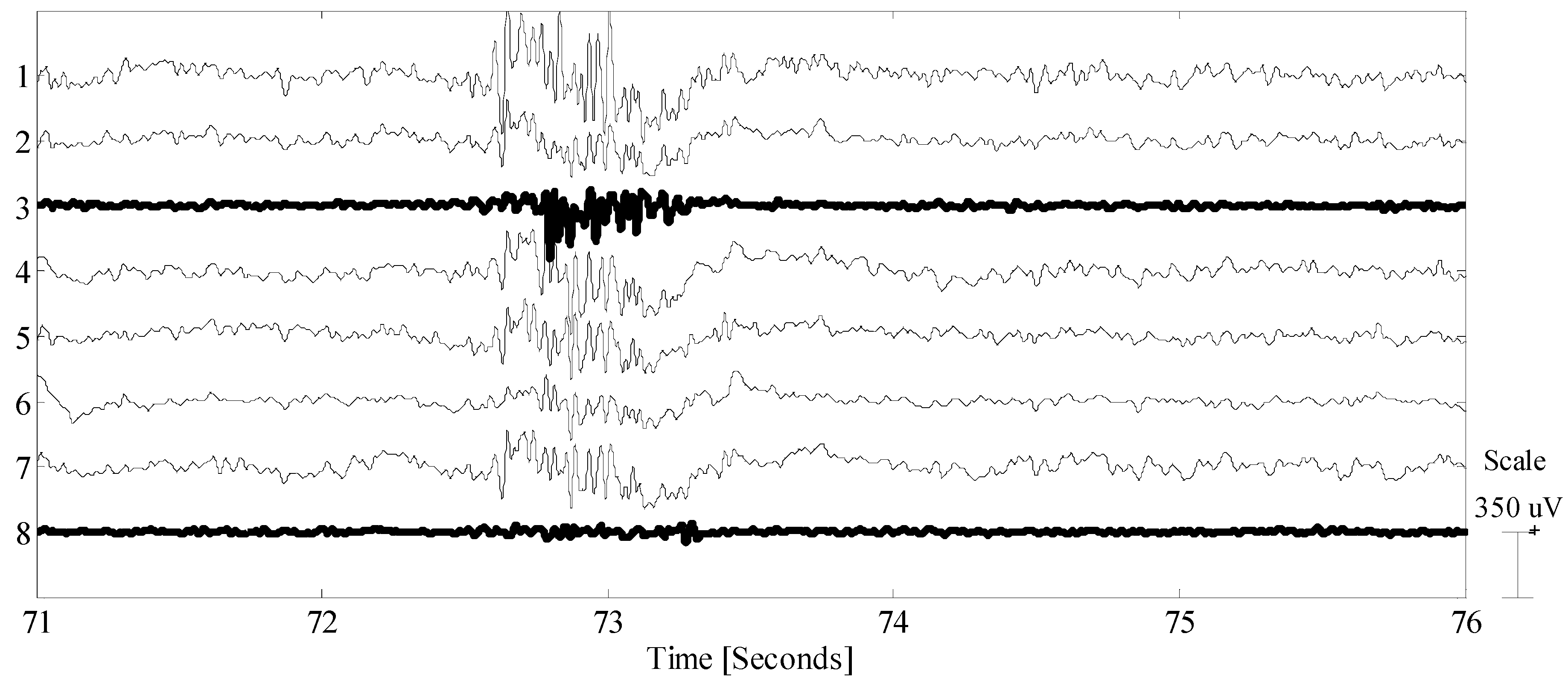
3. Results
4. Conclusions and Discussion
Supplementary Materials
Author Contributions
Funding
Acknowledgments
Conflicts of Interest
Appendix A. PGA Modification
Appendix B. Comparison with Some Popular EEG Systems and BCI2000 Test Run

| System Name/Website | EEG Channels | Electrodes | POWER SUPPLY | Noise Characteristics | Input Impedance | ADC Resolution/Sample Rate | BCI 2000 | Other Features |
|---|---|---|---|---|---|---|---|---|
| Our system/(see Supplementary Materials) | Up to 32 | Dry/wet user defined montage | Up to ±18 V /8.5 mA @ ±9 V | Input shorted, in the 0 to 10 Hz bandwidth: 3 µVpp | >1015/2 Ω/pF/unbalance of 109 Ω [4,5,6,7,8,9,10,11] | 16-bit software spannable/1 kHz | yes | Grounding configuration: user selectable |
| Cognionics/www.cognionics.net/quick-20 | 8 or 20 | Dry/wet (active electrodes) fixed montage | NA | Noise: 0.7 μV RMS from 1–50 Hz, shorted inputs | NA | 24-bit/ 250/500/1k/2k SPS | yes | Inertial sensor |
| Emotiv/https://www.emotiv.com | 14 | wet | NA | NA | NA | 14-bit/128 or 256 SPS | no | Inertial sensor |
| wearablesensing/https://wearablesensing.com | 7 (other configuration available | Dry/wet (active)user defined montage | NA (claimed 12 h battery life) | Noise (1–50 Hz) < 3 µVpp | 47 GΩ 25 pA bias current | 16-bit/300 SPS | no | Spring loaded |
| ABM/www.advancedbrainmonitoring.com/ | 9 or 20 | Wet fixed montage and reference | ~40 mA powered by 3.7 V | ~+2 µV @ 10 Hz and 50 kΩ impedance @ 256 s/s | 100 GΩ | 16/256 SPS | No | Other caps available |
| mBraintrain/https://mbraintrain.com/ | Several options | Flexible matrix, fixed configuration | NA | NA | NA | NA | No | NA |
| OpenBCI/https://openbci.com/ | 8 | Wet/dry (see TI ADS1299) | NA | NA (see TI ADS1299) | NA (see TI ADS1299) | 24-bit/up to 10k SPS | No | Arduino compatible |
References
- Prutchi, D.; Norris, M. Design and Development of Medical Electronic Instrumentation; Wiley: Hoboken, NJ, USA, 2005. [Google Scholar]
- Webster, J.G. (Ed.) Medical Instrumentation Application and Design; John Willey: Hoboken, NJ, USA, 2009. [Google Scholar]
- Malmivuo, J.; Plonsey, R. Bioelectromagnetism: Principles and Applications of Bioelectric and Biomagnetic Fields; Oxford University Press: Oxford, UK, 1995. [Google Scholar]
- Gargiulo, G.; Bifulco, P.; Calvo, R.A.; Cesarelli, M.; Jin, C.; Van Schaik, A. A Mobile EEG System with Dry Electrodes. In Proceedings of the 2008 IEEE Biomedical Circuits and Systems Conference, Baltimore, MD, USA, 20–22 November 2008. [Google Scholar]
- Gargiulo, G.; Bifulco, P.; Calvo, R.A.; Cesarelli, M.; Jin, C.; Van Schaik, A. Mobile biomedical sensing with dry electrodes. In Proceedings of the 2008 International Conference on Intelligent Sensors, Sensor Networks and Information Processing, Sydney, Australia, 15–18 December 2008. [Google Scholar]
- Gargiulo, G.; Bifulco, P.; Calvo, R.A.; Cesarelli, M.; Jin, C.; McEwan, A.; Van Schaik, A. Electronic Biosensor Circuits and Systems. In Intelligent and Biosensors; Somerset, V.S., Ed.; IntechOpen: London, UK, 2010. [Google Scholar]
- Gargiulo, G.; Bifulco, P.; Cesarelli, M.; Jin, C.; McEwan, A.; Van Schaik, A. Wearable dry sensors with Bluetooth connection for use in remote patient monitoring systems. In Studies in Health Technology and Informatics; Smith, A.C., Maeder, A.J., Eds.; IOS Press: Amsterdam, The Netherlands, 2010. [Google Scholar]
- Gargiulo, G.; Bifulco, P.; Cesarelli, M.; Ruffo, M.; Romano, M.; Calvo, R.A.; Jin, C.; Van Schaik, A. An Ultra-high Input Impedance ECG Amplifier for Long Term Monitoring of Athletes. Med. Devices 2010, 3, 1–9. [Google Scholar] [CrossRef]
- Gargiulo, G.; Bifulco, P.; McEwan, A.; Tehrani, J.N.; Calvo, R.A.; Romano, M.; Ruffo, M.; Shephard, R.; Cesarelli, M.; Jin, C.; et al. Dry electrode bio-potential recordings. In Proceedings of the 2010 Annual International Conference of the IEEE Engineering in Medicine and Biology Society (EMBC), Buenos Aires, Argentina, 31 August–4 September 2010. [Google Scholar]
- Gargiulo, G.; Calvo, R.A.; Bifulco, P.; Cesarelli, M.; Jin, C.; Mohamed, A.; Van Schaik, A. A new EEG recording system for passive dry electrodes. Clin. Neurophys. 2010, 121, 686–693. [Google Scholar] [CrossRef] [PubMed]
- Bifulco, P.; Cesarelli, M.; Fratini, A.; Ruffo, M.; Pasquariello, G.; Gargiulo, G. A wearable device for recording of biopotentials and body movements. In Proceedings of the 2011 IEEE International Symposium on Medical Measurements and Applications, Bari, Italy, 30–31 May 2011. [Google Scholar]
- Pregenzer, M.; Pfurtscheller, G. Frequency component selection for an EEG-based brain to computer interface. IEEE Trans. Rehabil. Eng. 1999, 7, 413–419. [Google Scholar] [CrossRef] [PubMed]
- Birbaumer, N.; Kübler, A. The thought translation device (TTD) for completely paralyzed patients. IEEE Trans. Rehabil. Eng. 2000, 8, 190–193. [Google Scholar] [CrossRef] [PubMed]
- Guger, C.; Schlogl, A.; Neuper, C.; Walterspacher, D.; Strein, T.; Pfurtscheller, G. Rapid prototyping of an EEG-based brain-computer interface (BCI). IEEE Trans. Neural Syst. Rehab. Eng. 2001, 9, 49–58. [Google Scholar] [CrossRef]
- Pfurtsheller, G.; Neuper, C. Motor Imagery and Direct Brain–Computer Communication. Proc. IEEE 2001, 89, 1123–1134. [Google Scholar] [CrossRef]
- Wolpaw, J.R.; Birbaumer, N.; McFarland, D.J.; Pfurtscheller, G.; Vaughan, T.M. Brain–computer interfaces for communication and control. Clin. Neurophysiol. 2002, 113, 5. [Google Scholar] [CrossRef]
- Teplan, M. Fundamentals of eeg measurement. Meas. Sci. Rev. 2002, 2, 1–11. [Google Scholar]
- Waterhouse, E. New Horizons in Ambulatory Electroencephalography. IEEE Eng. Med. Biol. Mag. 2003, 22, 74–80. [Google Scholar] [CrossRef] [PubMed]
- Gargiulo, G.; Bifulco, P.; Calvo, R.A.; Cesarelli, M.; Jin, C.; McEwan, A.; Van Schaik, A. Non-invasive electronic biosensor circuits and systems. In Intelligent and Biosensors; InTech: London, UK, 2010. [Google Scholar]
- Gargiulo, G.D.; Mohamed, A.; McEwan, A.L.; Bifulco, P.; Cesarelli, M.; Jin, C.T.; Ruffo, M.; Tapson, J.; Van Schaik, A. Investigating the role of combined acoustic-visual feedback in one-dimensional synchronous brain computer interfaces, a preliminary study. Med. Devices 2012, 5, 81. [Google Scholar] [CrossRef] [PubMed]
- Alizadeh-Taheri, B.; Smith, R.L.; Knight, R.T. An active microfabricated scalp electrode array for EEG recording. Sens. Actuators A Phys. 1996, 54, 606–611. [Google Scholar] [CrossRef]
- Popescu, F.; Fazli, S.; Badower, Y.; Blankertz, B.; Muller, K.-R. Single Trial Classification of Motor Imagination Using 6 Dry EEG Electrodes. PLoS ONE 2007, 2, 7. [Google Scholar] [CrossRef] [PubMed]
- Sullivan, T.J.; Deiss, S.R.; Jung, T.-P.; Cauwenberghs, G. A Brain-Machine Interface using Dry-Contact, Low-Noise EEG Sensors. In Proceeding of the 2008 IEEE International Symposium on Circuits and Systems, Seattle, WA, USA, 18–21 May 2008. [Google Scholar]
- Estepp, J.R.; Monnin, J.W.; Christensen, J.C.; Wilson, G.F. Validation of a Dry Electrode System for EEG. In Proceeding of the Human Factors and Ergonomics Society Annual Meeting, San Antonio, TX, USA, 19–23 October 2009. [Google Scholar]
- Nga, W.C.; See, H.L.; Leea, K.S.; Ninga, N.; Tai, W.X.; Sutedja, M.; Fuha, J.Y.H.; Li, X.P. Micro-spike EEG electrode and the vacuum-casting technology for mass production. J. Mate. Proc. Technol. 2009, 209, 5. [Google Scholar] [CrossRef]
- Brunner, P.; Bianchi, L.; Guger, C.; Cincotti, F.; Schalk, G. Current trends in hardware and software for brain–computer interfaces (BCIs). J. Neural Eng. 2011, 8, 1–7. [Google Scholar] [CrossRef] [PubMed]
- Grozea, C.; Voinescu, C.D.; Fazli, S. Bristle-sensors—Low-cost flexible passive dry EEG electrodes for neurofeedback and BCI applications. J. Neural Eng. 2011, 8, 025008. [Google Scholar] [CrossRef] [PubMed]
- Mihajlovic, V.; Molina, G.G.; Peuscher, J. To what extent can dry and water-based EEG electrodes replace conductive gel ones?: A Steady State Visual Evoked Potential Brain-Computer Interface Case Study. In Proceedings of the 2011 International Conference on Biomedical Engineering, Venice, Italy, 23–25 November 2011. [Google Scholar]
- Pour, P.A.; Gulrez, T.; AlZoubi, O.; Gargiulo, G.; Calvo, R.A. Brain-computer interface: Next generation thought controlled distributed video game development platform. In Proceedings of the 2018 IEEE Symposium On Computational Intelligence and Games, Perth, Australia, 15–18 December 2008. [Google Scholar]
- Gaetano, G.; Bifulco, P.; Calvo, R.A.; Van Schaik, A. Chapter 8. Giga-Ohm High-Impedance FET Input Amplifiers for Dry Electrode Biosensor Circuits and Systems. Available online: https://www.researchgate.net/profile/Gaetano_Gargiulo3/publication/260294087_Giga-ohm_high_impedance_FET_input_amplifiers_for_dry_electrode_biosensor_circuits_and_systems/links/5834a5cb08ae138f1c0d7eea.pdf (accessed on 9 February 2019).
- Gargiulo, G. System for sensing electrophysiological signals. U.S. Patent 13/002,904, 7 July 2011. [Google Scholar]
- Gargiulo, G.D.; Shephard, R.W.; Tapson, J.; McEwan, A.L.; Bifulco, P.; Cesarelli, M.; Jin, C.; Al-Ani, A.; Wang, N.; Van Schaik, A. Pregnancy detection and monitoring in cattle via combined foetus electrocardiogram and phonocardiogram signal processing. BMC Veterinary Res. 2012, 8, 164. [Google Scholar] [CrossRef] [PubMed]
- BurrBrown. INA116. Available online: http://www.ti.com/lit/ds/symlink/ina116.pdf (accessed on 9 February 2019).
- Gargiulo, G. Portable Bio-Signals Devices for Brain Computer Interface and Long-Term Patient Monitoring. Ph.D. Thesis, University of Bologna, Bologna, Italy, 2010. [Google Scholar]
- Winter, B.B.; Webster, J.G. Reduction of Interference Due to Common Mode Voltage in Biopotential Amplifiers. IEEE Trans. Biomed. Eng. 1983, BME-30, 58–62. [Google Scholar] [CrossRef]
- Gargiulo, G.; McEwan, A.; Bifulco, P.; Cesarelli, M.; Jin, C.; Tapson, J.; Thiagalingam, A.; Van Schaik, A. Towards true unipolar ECG recording without the Wilson central terminal (preliminary results). Physiolog. Meas. 2013, 34, 991. [Google Scholar] [CrossRef]
- Gargiulo, G.D.; Tapson, J.; Van Schaik, A.; McEwan, A.; Thiagalingam, A. Unipolar ECG circuits: Towards more precise cardiac event identification. In Proceedings of the 2013 IEEE International Symposium on Circuits and Systems (ISCAS), Beijing, China, 19–23 May 2013. [Google Scholar]
- Gargiulo, G.; Tapson, J.C.; Shephard, R.W. Non-invasively measuring physiological process. U.S. Patent 8,652,063, 18 February 2014. [Google Scholar]
- Gargiulo, G.D. True unipolar ECG machine for Wilson Central Terminal measurements. BioMed Res. Int. 2015, 2015, 586397. [Google Scholar] [CrossRef]
- Gargiulo, G.D.; Varaki, E.S.; Hamilton, T.J.; Bifulco, P.; Cesarelli, M.; Romano, M. A 9-independent-leads ECG system from 10 electrodes: A practice preserving WCT-less true unipolar ECG system. In Proceedings of the 2015 IEEE Biomedical Circuits and Systems Conference (BioCAS), Atlanta, GA, USA, 22–24 October 2015. [Google Scholar]
- AMINOFF, M.J. Evoked Potentials in Clinical Medicine. Q. J. Med. 1986, 59, 345–362. [Google Scholar]
- Takei, K.; Nakano, H.; Hommura, S.; Iketani, N. Analysis of the Components of Electrically Evoked Response Using a Monopolar Recording Technique. Invest. Ophthalmol. Vis. Sci. 1993, 34, 1923–1929. [Google Scholar] [PubMed]
- Donchin, E.; Spencer, K.M.; Wijesinghe, R. The Mental Prosthesis: Assessing the Speed of a P300-Based Brain–Computer Interface. IEEE Trans. Rehabil. Eng. 2002, 8, 174–179. [Google Scholar] [CrossRef]
- Brigell, M.; Bach, M.; Barber, C.; Moskowitz, A.; Robson, J. Guidelines for calibration of stimulus and recording parameters used in clinical electrophysiology of vision. Doc. Ophthalmol. 2004, 107, 185–193. [Google Scholar] [CrossRef]
- Durka, P.J.; Zygierewicz, J.; Klekowicz, H.; Ginter, J.; Blinowska, K.J. On the Statistical Significance of Event-Related EEG Desynchronization and Synchronization in the Time-Frequency Plane. IEEE Trans. Biomed. Eng. 2004, 51, 1167–1175. [Google Scholar] [CrossRef] [PubMed]
- Wu, R.-C.; Liang, S.-F.; Lin, C.-T.; Hsu, C.-F. Applications of Event-Related-Potential-Based Brain Computer Interface to Intelligent Transportation Systems. In Proceedings of the 2004 IEEE International Conference on Networking, Sensing & Control, Taipei, Taiwan, 21–23 March 2004. [Google Scholar]
- Gargiulo, G.D.; Bifulco, P.; Cesarelli, M.; McEwan, A.; Wabnitz, A. Open platform, 32-channel, portable, data-logger with 32 PGA control lines for wearable medical device development. Electron. Lett. 2014, 50, 1127–1129. [Google Scholar] [CrossRef]
- Aiello, O.; Gargiulo, G.; McEwan, A. Instrumented flexible active electrode matrix suitable for human-computer interface applications. Biomed. Phys. Eng. Express 2016, 2, 035020. [Google Scholar] [CrossRef]
- Gargiulo, G.D.; Bifulco, P.; Cesarelli, M.; Fratini, A.; Romano, M. Problems in assessment of novel biopotential front-end with dry electrode: A brief review. Machines 2014, 2, 87–98. [Google Scholar] [CrossRef]
- Horowitz, P.; Hill, W. The Art Of Electronics; Cambridge University Press: Cambridge, UK, 2002. [Google Scholar]
- Ruffo, M.; Cesarelli, M.; Jin, C.; Gargiulo, G.; McEwan, A.; Sullivan, C.; Bifulco, P.; Romano, M.; Shephard, R.W.; Van Schaik, A. Non invasive foetal monitoring with a combined ECG-PCG system. In Biomedical Engineering, Trends in Electronics, Communications and Software; IntechOpen: London, UK, 2011. [Google Scholar]
- Gargiulo, G.D.; McEwan, A.L.; Bifulco, P.; Cesarelli, M.; Jin, C.; Tapson, J.; Thiagalingam, A.; Van Schaik, A. Towards true unipolar bio-potential recording: A preliminary result for ECG. Physiol. Meas. 2012, 34, N1. [Google Scholar] [CrossRef]
- BurrBrown. OPA244 series MicroPower, Single-Supply OPERATIONAL AMPLIFIERS MicroAmplifier™ Series. Available online: http://www.ti.com/product/OPA244 (accessed on 9 February 2019).
- AnalogDevices. AD5290 Compact +30 V/±15 V 256-Position Digital Potentiometer. Available online: https://www.jameco.com/Jameco/Products/ProdDS/1778421.pdf (accessed on 9 February 2019).


| Number of analogue channels | 8 per module, BIOADC supports 4 modules |
| Electrodes compatibility/electrodes configuration | Passive dry/wet up to contact impedance unbalance of 109 Ω [4,5,6,7,8,9,10,11]/user defined i.e., clustered or 10–20 |
| Electrode montage | Differential/unipolar (user selectable) |
| Power supply | Up to ±18 V |
| Current consumption | 8.5 mA when powered by ±9 V |
| Input impedance | >1015/2 Ω/pF |
| Input referred noise (shorted inputs) | Up to 10 Hz bandwidth 3 µVpp |
| ADC resolution (BIOADC) | 16-bit (software span-able) |
© 2019 by the authors. Licensee MDPI, Basel, Switzerland. This article is an open access article distributed under the terms and conditions of the Creative Commons Attribution (CC BY) license (http://creativecommons.org/licenses/by/4.0/).
Share and Cite
Gargiulo, G.D.; Bifulco, P.; Cesarelli, M.; McEwan, A.; Nikpour, A.; Jin, C.; Gunawardana, U.; Sreenivasan, N.; Wabnitz, A.; Hamilton, T.J. Fully Open-Access Passive Dry Electrodes BIOADC: Open-Electroencephalography (EEG) Re-Invented. Sensors 2019, 19, 772. https://doi.org/10.3390/s19040772
Gargiulo GD, Bifulco P, Cesarelli M, McEwan A, Nikpour A, Jin C, Gunawardana U, Sreenivasan N, Wabnitz A, Hamilton TJ. Fully Open-Access Passive Dry Electrodes BIOADC: Open-Electroencephalography (EEG) Re-Invented. Sensors. 2019; 19(4):772. https://doi.org/10.3390/s19040772
Chicago/Turabian StyleGargiulo, Gaetano D., Paolo Bifulco, Mario Cesarelli, Alistair McEwan, Armin Nikpour, Craig Jin, Upul Gunawardana, Neethu Sreenivasan, Andrew Wabnitz, and Tara J. Hamilton. 2019. "Fully Open-Access Passive Dry Electrodes BIOADC: Open-Electroencephalography (EEG) Re-Invented" Sensors 19, no. 4: 772. https://doi.org/10.3390/s19040772