Ultrasound Systems for Biometric Recognition


School of Engineering, University of Basilicata, 85100 Potenza, Italy
Sensors 2019, 19(10), 2317; https://doi.org/10.3390/s19102317
Submission received: 31 March 2019
/
Revised: 25 April 2019
/
Accepted: 15 May 2019
/
Published: 20 May 2019
(This article belongs to the Section Physical Sensors)
Abstract
:Biometric recognition systems are finding applications in more and more civilian fields because they proved to be reliable and accurate. Among the other technologies, ultrasound has the main merit of acquiring 3D images, which allows it to provide more distinctive features and gives it a high resistance to spoof attacks. This work reviews main research activities devoted to the study and development of ultrasound sensors and systems for biometric recognition purposes. Several transducer technologies and different ultrasound techniques have been experimented on for imaging biometric characteristics like fingerprints, hand vein pattern, palmprint, and hand geometry. In the paper, basic concepts on ultrasound imaging techniques and technologies are briefly recalled and, subsequently, research studies are classified according to the kind of technique used for collecting the ultrasound image. Overall, the overview demonstrates that ultrasound may compete with other technologies in the expanding market of biometrics, as the different commercial fingerprint sensors integrated in portable electronic devices like smartphones or tablets demonstrate.
1. Introduction
At first, biometric recognition systems were mainly exploited for applications in public security and criminal investigation but, more recently, they are being used in more and more civilian fields because they proved to be reliable and accurate. Several possible biometric characteristics can be used, including face, iris, fingerprint. The choice depends on the specific application; to this end several issues have to be taken into account: universality (all people should have the characteristic), uniqueness, permanence over a reasonable period of time, collectability, acceptability, performance and circumvention (should be resistant to spoof attacks) [1,2]. The human hand has been employed for extracting various biometric features like fingerprint, palmprint, hand geometry and hand vein pattern. Fingerprint has been used in criminal investigation since the early 1900s, and, nowadays, it is still one of the most popular biometrics [3,4,5]. A fingerprint contains information on ridge and valley patterns of a human fingertip. Depending on sensor resolution, there are different types of features that can be exploited in recognition processes [6]: at global level patterns like loop, whorl, and arch, at local level patterns like ridge endings and bifurcations called minutiae and, finally, at intra-ridge level patterns of sweet pores.
The palm of the human hand contains patterns of ridges and valleys similar to those of the finger [7,8,9] and, due to its larger area, palmprint should be even more distinctive than fingerprint, but slower. Another possibility is to acquire a palm image with a low resolution scanner; in this case, extracted features are principal lines and wrinkles only [10,11]. Low-resolution palmprint images are mainly used in access control applications.
Hand vein pattern is a biometric characteristic that is attracting growing attention from both researchers and companies [12,13]. Vascular patterns of the hand are very distinctive and stable over a long period of time [14]; also, they are very difficult to counterfeit because they cannot be seen by the human eye as they are hidden under the skin.
Hand geometry uses measurements of palm size, finger length and width as features [15]. Recognition systems based on hand geometry are quite simple and inexpensive but they are only suited for a relatively small population group.
For many years, biometric recognition systems only exploited 2D images and features, despite of the fact that human characteristics are 3D. More recently, several methods have been proposed for achieving 3D information from biometric characteristics like face, palmprint, fingerprint and ear [16].
A recognition system that uses only one biometric characteristic is known as unimodal while, if two or more independent characteristics are collected, the system is called multimodal. This last recognition modality is often used when there is the need to improve the recognition rate [17,18,19].
Several technologies have been used to acquire images of the various biometrics including optical, capacitive, thermal and infrared. The main merit of ultrasound over other technologies is the capability of collecting volumetric images of the investigated biometrics, which produces twofold benefits: the possibility to extract features that are more distinctive and a very strong resistance to spoof attacks. In addition, ultrasound images do not suffer from many kinds of surface contaminations, humidity or ambient light.
The present work reviews research activities devoted to develop ultrasound systems for biometric recognition purposes. Several sensor technologies, from classic piezoelectric or piezocomposite transducers to the most recent capacitive and piezoelectric micromachined ultrasonic transducers, CMUT and PMUT, respectively, as well as different imaging techniques have been experimented over the years. Fingerprint is the most investigated biometric characteristic, especially since it was clear that authentication in smartphone devices would have been done mainly through fingerprint. The possibility of collecting other biometrics including vein pattern, palmprint, hand geometry has been explored as well in the recent literature. In the present paper, research studies are classified according to the kind of ultrasound technique exploited for acquiring the image. Hereafter, Section 2 briefly recalls main ultrasound techniques and transducer technologies used for imaging the human body. Section 3 and Section 4 analyze research papers that used pulse-echo and impediography techniques, respectively. In Section 5, works that experimented with different approaches are presented and, finally, conclusions are drawn in Section 6.
2. Fundamentals of Ultrasonics
Even if piezoelectricity was discovered by Jacques and Pierre Curie in 1880, the first human application of ultrasound was due to the French physicist Paul Langevin who, after the Titanic sinking (1912), started experimental studies that brought to first sound navigation and ranging (SONAR) transducers based on quartz to detect icebergs and submarines [20,21,22].
Later on, a strong impulse to ultrasonic applications came with the discovery of strong and stable piezoelectric properties in ceramic materials like barium titanate, lead niobate and mostly lead zirconate titanate (PZT). These materials, being composed of solid mixtures of powders, are able to provide a wide range of operating parameters [23].
Nowadays, ultrasound is applied to several fields. For example, ultrasound imaging or sonography is widely employed in medicine and in nondestructive evaluation of products and structures, where it is used to reveal invisible flaws, but also to detect objects and measure distances. Other industrial applications of ultrasound include cleaning, mixing, and accelerating chemical processes.
2.1. Ultrasound Imaging Techniques
Ultrasonic images are a very useful tool in medical diagnostics and new techniques are continuously developed [24,25,26]. 3D ultrasound is used in several applications because it is able to provide more complete information on human anatomy than 2D ultrasound [27,28,29]. Main techniques able to provide ultrasonic images are briefly described in the following.
2.1.1. Pulse-Echo Imaging
The basic modality of pulse-echo imaging is the amplitude (A)-mode: the wave transmitted by a transducer propagates through the body and reflected echoes provide information on the depth of tissue interfaces. The simplest way to obtain a two-dimensional image consists in moving the single transducer along a direction while acquiring several A-modes. After processing the A-line signals, a cross-sectional image is obtained and with some further processing a gray scale brightness (B)-mode image can be rendered. B-mode images are usually obtained by exploiting an array of transducers, which is faster and more effective because of the electronic scan and allows beamforming techniques like focusing, steering and apodization.
Similarly, three-dimensional ultrasound images can be obtained either using a single transducer and performing mechanical scans along two orthogonal directions or using a linear array and performing a single mechanical scan. Another possibility relies in the use of 2D transducer arrays, which however imply severe technological challenges [30,31].
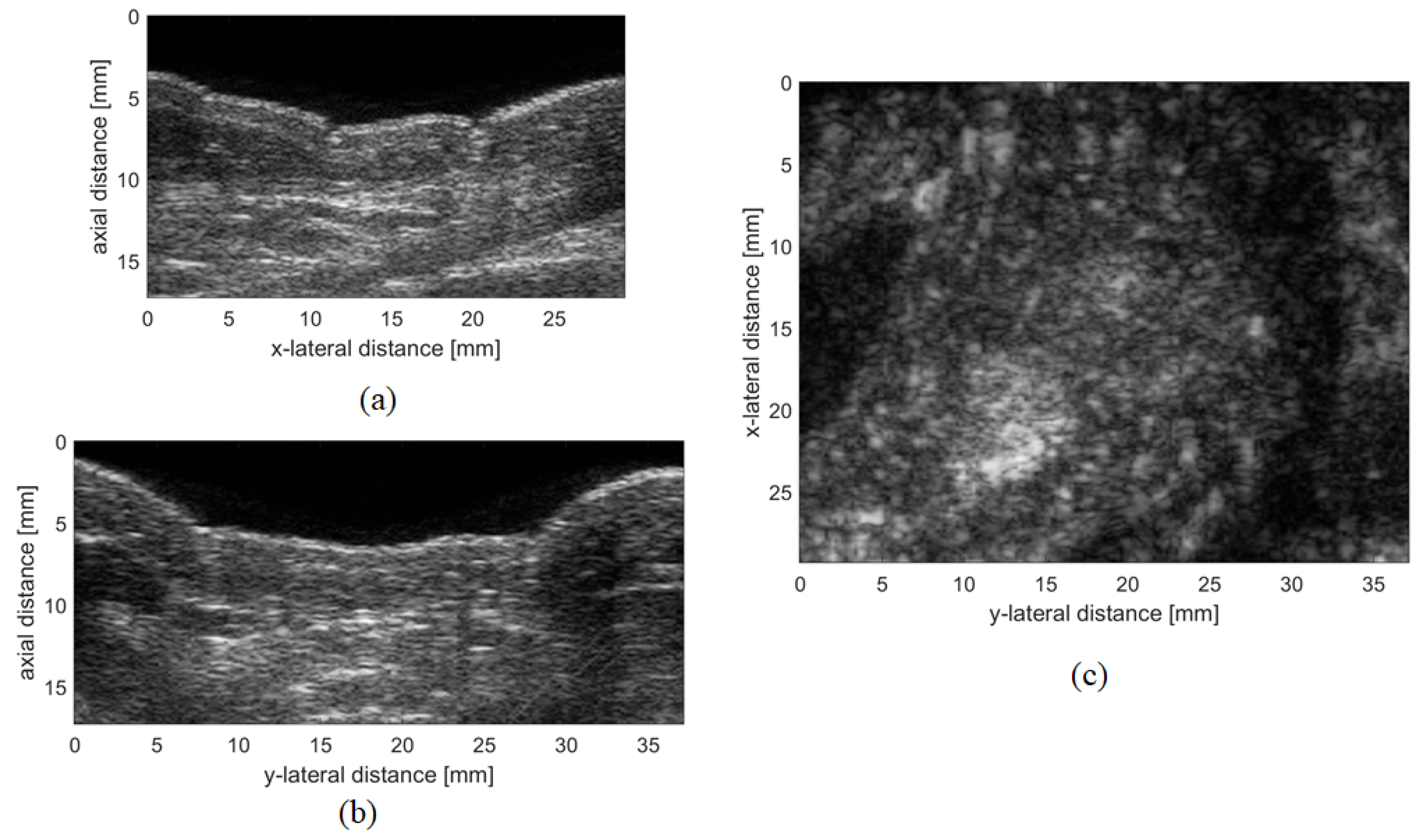
A C-mode image is a 2D image orthogonal to a B-mode image, at a given depth from the transducer. Whenever a volumetric image is acquired, any B-mode or C-mode image can be easily extracted as shown in Figure 1.
Doppler ultrasound imaging is widely used in cardiovascular analysis. It exploits the Doppler effect and is able to image the movement of tissues or blood. Color Doppler images are often superimposed to B-mode images and provide information on the speed and direction of the motion in a color scale. Power Doppler ultrasound, instead, displays only blood flow, but with better detail than color Doppler [32,33].
2.1.2. Impediography
The above-mentioned methods use the pulse-echo technique to provide images that map the reflectivity of scanned tissues. Another possibility to achieve acoustical images consists in evaluating the acoustic impedance of the load by means of a simple measurement of the electric impedance of the transducer. This technique is usually known as impediography: when the ultrasonic wave finds a change of acoustical impedance, part of the energy is transmitted and part is reflected [24]. The higher is the difference between the acoustic impedances of transducer and load, the higher is the reflected wave. Based on this simple principle, loads with different acoustic impedances can be distinguished by simply analyzing the electrical impedance of the transducer. As an example, Figure 2 shows the electric impedance of a single piezoceramic element, which has an acoustic impedance of around 30 MRayl, simulated by using a 1D model [20,23], when it is loaded by water (acoustic impedance about 1.5 MRayl) and air (acoustic impedance about 400 Rayl), respectively.
As can be seen, different loads can be easily detected by evaluating the minimum value of the electrical impedance modulus (which occurs approximately at the series resonance frequency ).
2.1.3. Other Techniques
There are other techniques that can be exploited to produce ultrasound images, including photoacoustics and acoustic holography.
The photoacoustic (PA) effect allows the conversion of light to sound. When a tissue is exposed to high energy, like for example laser light, it absorbs part of this energy causing localized heating and rapid thermoelastic expansion that produces transient broadband ultrasound waves [34]. The magnitude of the ultrasonic signal directly depends on the local energy deposition; in this way, 2D or 3D images of the areas of interest can be formed [35].
Near-field acoustic holography (NAH) is a technique that is based on performing a measurement in the near field of the source with a number of transducers and then on reconstructing the whole three-dimensional sound field. NAH allows to estimate sound pressure, particle velocity, and sound intensity vectors in a different position than the one measured, achieving enhanced spatial resolution, because it also acquires evanescent waves in the near-field [36].
2.2. Transducer Technologies
To be used in medical diagnostic imaging, ultrasonic transducers should be able to generate and receive short pulses with high sensitivity and spatial resolution in the MHz frequency range.
Piezoceramic materials like PZT are good candidates because of their high electromechanical coupling factor. However, they have a high acoustic impedance (about 30 MRayl) while that of the human body is around 1.5 MRayl. Consequently, a direct application of a PZT element would produce a high impedance mismatch, resulting in a high quality factor Q [37]. In order to increase transducer bandwidth, two adjustments are usually adopted. The first one consists of using an adequate backing material, which absorbs a large part of the energy transmitted by the piezoelement. The second one consists in inserting at least one impedance matching layer at the front of the transducer. Several theoretical and experimental analysis aimed to optimize the design of the matching layer, depending on the application, can be found in the literature [38,39,40,41]. An acoustic lens is often added to enhance resolution. When applied to the human body, a coupling medium (usually water or gel) is interposed between transducer and skin in order to avoid air bubbles that would reflect the ultrasound wave.
Nowadays, transducers based on piezocomposite technology are those used in most of the applications, while the emerging technologies of micromachined ultrasonic transducers (MUTs) are demonstrating very attractive, mainly because of their capability to integrate transducer and electronics in only one chip.
2.2.1. Piezocomposite Transducers
Piezocomposite material is an important update of bulk piezoceramic. Piezocomposite transducers were introduced in the early eighties of the past century [42]. These materials are made by combining piezoceramic elements with epoxy or other polymer materials. The percentage of PZT material is usually less than 30 %, which results in a drastic decrease of the whole acoustic impedance and hence in a better coupling with the human body. Most commonly piezocomposite transducers used in medical ultrasonic imaging are of the 1–3 and 2–2 connectivity [33].
2.2.2. CMUT
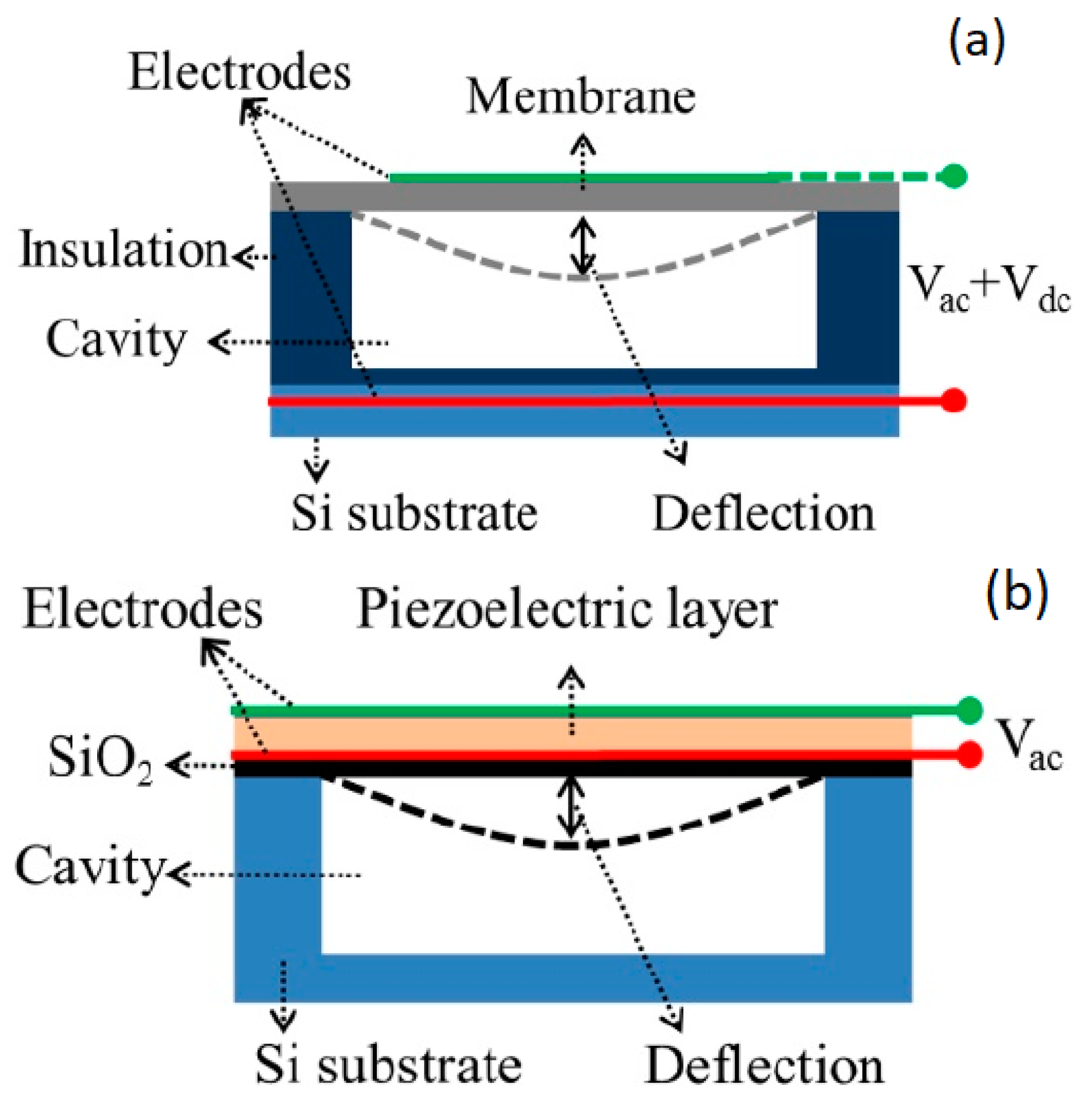
A capacitive micromachined ultrasonic transducer (CMUT) is composed of a high number of cells vibrating in flexural mode [46,47]. A single cell is schematically described in Figure 3a. Basically, it is a small capacitor where one of the electrodes is deposed on a silicon nitride membrane, which is suspended on an air cavity, while the other one is in the silicon substrate. A bias voltage of more than 100 V has to be applied together with the alternate signal to produce the flexural vibration of the membrane. As CMUT has a very low mechanical impedance, it was first conceived for in-air applications [48], but subsequent in-water experiments demonstrated its suitability for medical diagnostic applications, mainly thanks to its wide frequency bandwidth [49,50]; hence, several different technological solutions for CMUT realization have been proposed during the years [51,52,53]. The possibility of integration of CMUT with CMOS technology has been demonstrated as well [54], even if the high bias voltage may limit integration in portable devices.
2.2.3. PMUT
Piezoelectric micromachined ultrasonic transducers (PMUTs), similar to CMUTs, are based on a flexural vibration of a membrane (see Figure 3b) but, in this case, the membrane is composed of at least one piezoelectric layer and one passive elastic layer. The lateral strain generated from the first one is contrasted by the second one, resulting in a flexural motion [55,56,57,58]. A main merit of PMUT over CMUT is that PMUT doesn’t need for high biasing voltages, which allows for an easier integration into portable electronics. PMUT devices are realized by using two main piezoelectric materials: aluminum nitride (AlN) and PZT. The much higher piezoelectric constants of PZT makes it preferable whenever high performance devices have to be realized, while AlN MEMS devices are usually used when integration with electronics is the primary issue, due to their compatibility with the CMOS process [59,60]. An important drawback of the PMUT is the relatively low bandwidth; to solve this issue several solution are being investigated [57,61].
3. Biometric Systems Based on Pulse-Echo Imaging
First experiments devoted to acquire live scan fingerprint images through an ultrasound system were probably carried out in the early nineties of the past century at Niagara Technology Laboratories, Buffalo, New York (USA) [62,63]. As probe the authors used a single piezoelectric transducer, with a fixed focus and aperture size of 6.35 mm, working at 30 MHz and operating in pulse-echo modality. An external focusing lens with focal length of 25 mm allows the transducer to produce a spot size of about 0.2 mm. The finger is placed on a collimated lens made of polystyrene and acoustically coupled through water. The ultrasonic beam from the transducer strikes a rotating acoustic mirror and is redirect to the lens, which basically converts the scan geometry from B-mode to C-mode. The echoes are sent back to the transducer to be processed and stored by the electronics. The same operation is repeated while a linear actuator moves the whole assembly along a direction orthogonal to the scan line and acquires successive lines of the fingerprint. In this way a total area of 19 × 19 mm was scanned and the achieved plain fingerprint rendered. The system resulted cheap and fast if compared to commercial high performance and cost scanning systems of that period, yet the achieved image quality was not adequate because the focal length of the transducer was too short. Some years later, the research group proposed an acquisition system based on a tightly focused transducer (frequency 30 MHz, aperture about 7.4 mm, focal length 5.9 mm) that is swept across the whole fingerprint area: a torque actuator, attached to a high resolution optical encoder, moves the transducer along one direction, while a brushless DC stepper motor provides the scan along a perpendicular axis [63,64]. This approach, even if more complex, guaranteed a resolution of 500 dpi. Acquired images of fingers contaminated by ink demonstrated that, different from optical systems, ultrasound images are not affected by such kind of contamination.
The idea to reproduce an ultrasonic fingerprint image by means of mechanical scans along two orthogonal axes was resumed few years later [65]. In this case a focused transducer working at 50 MHz allowed to achieve a resolution of 1000 dpi. The finger is pressed against a polystyrene plate 2 mm thick; to achieve good acoustic coupling, a gel layer is put between plate and finger and, furthermore, images are acquired in basin filled with water. The A-scan signals are then collected and stored in a 3D matrix and subsequently rendered in the form of several 2D images as B-mode or C-mode images. These images allow to visualize sweet pores that provide additional information and that cannot be detected with optical techniques. The shortcoming of this method is the relatively long acquisition time.
To overcome this limit the acquisition speed was greatly increased by exploiting a cylindrical scanning in one of the two directions [66]. To this end, several focused transducers are mounted on a cylinder that rotates around the finger. Transducers are turned on only when they face the area containing the fingerprint, while a linear scan along the axis of the cylinder allows to acquire the volumetric image. Successively, with the same approach, the research group demonstrated the possibility to obtain fingerprint patterns from under-skin layers, which makes the system independent from natural or voluntary deterioration of skin surface [67].
Another approach to achieve 3D ultrasound images of fingerprint used a 192 elements linear array probe, based on CMUT technology [52], which was specially designed for near-field ultrasound imaging [68]. To this end, a very small pitch, i.e., the distance between two elements of the array, was chosen (112 m) in order to have the focal region very close to the transducer (from 3 to 10 mm); an acoustic lens provides focusing in elevation at 6 mm. The transducer exhibits a wide bandwidth (about 100%) with center frequency of 12.5 MHz.
3D images of a fingertip were acquired by driving the probe with a commercial ultrasound imaging system (Technos-Esaote, Italy) and automatically moving it along the elevation direction. Water was used as coupling medium. Figure 4a shows a 3D representation of a collected fingerprint, while Figure 4b a 2D image extracted at an under-skin depth of 0.2 mm. In both images, sweat pores are clearly visible. The design of the array was subsequently optimized by means of a FE model [69], which accounts for the acoustic lens and the backing. The same set up was exploited to provide images of a region of the human palm as well, by using a similar CMUT probe but with a larger aperture [70].
A relevant research activity has been carried out to develop a fingerprint sensor based on a AlN PMUT 2D array integrated with portable device electronics. The first implementation consisted of a 24 × 8 array with pitch of 100 m, for a total area of 2.3 × 0.7 mm. The electronics was realized in 180 nm CMOS technology [71,72]. A plane wave is generated by driving all PMUT elements with a 28 V 2-cycle 22 MHz square-wave; in other experiments a 12 V 3-cycle 20 MHz square-waves is used instead. In both cases, one column is selected and the received signals from 8 elements are read out in parallel. The time employed to image a fingerprint area of 2.3 mm × 0.7 mm (same area of the sensor) was equal to 24 s. A mechanical scanning was performed to image higher areas; in this way, an image of a 2D polydimethylsiloxane (PDMS) fingerprint phantom with pitch of about 600 m was acquired by using a liquid coupling layer (Fluorinert). Also, the authors presented an experimental study where they demonstrate that a very thin layer of material, used for sensor protection, results transparent to acoustic reflection even if a high acoustic impedance mismatch occurs [73]. Subsequently, the same research group upgraded sensor’s design by increasing array’s size to 65 × 42 and then to 110 × 56 elements, arriving to acquire a fingerprint area of 4.73 × 3.25 mm [74,75,76,77,78,79]. The authors provided a full acoustic characterization of the device, which showed lateral and axial resolution of 75 and 150 , respectively, and an adequate contrast ratio between ridge and valley (5:1). Also this kind of sensor is able to collect fingerprint images at both the epidermis and the dermis layer. The overall characteristics of the device seem to be very close to the requirements of consumer electronics.
An example of PMUT based on PZT can be found in the literature as well [80]. The transducer is composed of an array of 50 × 50 PMUTs and is fabricated by using a sol-gel PZT technique. The size of the cells is 50 m while the pitch is 100 m. The device has a resonance frequency of about 25 MHz and exhibits very good electromechanical properties. However, even if it is claimed that the transducer was specially designed and simulated for fingerprint applications, no image has been provided yet.
A finite element method study investigated the feasibility of ultrasonic transducers based on 1–3 piezocomposite to detect fingerprint patterns trough pulse-echo methods [81].
As discussed in the introduction, the possibility of extracting more than one biometric characteristic from the same acquired volume, realizing in this way a multimodal biometric system, could improve the overall performances of the biometric system. Such approach was probably investigated for the first time for recognition purposes in [82]. In that paper, a commercial ultrasound system (GE Logiq-9 scanner with a 14 MHz GE M12L probe) was employed to image the inner structure of fingers to detect and measure anatomical elements as bone contour or tendon with the aim of using them as potential biometric identifiers. The 3D images were collected by moving the probe along the elevation direction and by acquiring B-mode images with an interval of 0.4 mm. Some verification experiments carried out on a small database have shown the potential of the proposed methods.
A similar ultrasound technique has been widely exploited to extract other biometric characteristics than fingerprint by acquiring a volumetric region of the human palm.
3D palm under-skin images were firstly presented in Refs. [83,84]. Also in those works, a commercial equipment was used (Technos ultrasound scanner with a 7.5 MHz LA523 probe, both from Esaote, Italy) and the acoustic coupling between probe and hand was realized through a gel pad; in this case, due to the larger investigated volume, a higher number of different human organs like tendons, muscles and veins were identified and measurements of their dimension, together with some distances among them, were proposed as a biometric template. In subsequent works, the same research group experimented with the same approach with the aim to extract 3D palmprint images [85,86]. With respect to previous experiments, a 12 MHz frequency probe (LA435, Esaote) was used; furthermore, the acoustic coupling was realized through water. Results have shown that two kinds of 3D information can be extracted: the 3D profile of the palm, which can be achieved with optical methods based on structured-light imaging as well [87], and palm lines’ depth, which instead can be achieved only with the ultrasound. The same set up was also used to extract, through power Doppler analysis, 3D palm vein patterns [88], which provide improved distinctiveness with respect to 2D vein patterns achievable with classical techniques (see Figure 5).
An improvement of the acquisition system was presented in Refs. [89,90]; the main difference with the previous set up was the use of a different ultrasonic scanner [91] to replace the previous one, which had shown a too long acquisition time. With the new system, the authors established a database and defined 3D feature extraction procedures based on both palm curvature [92] and line depth analysis [93,94,95]. Figure 6a shows a 3D render of a collected palm where the curvature can be appreciated and Figure 6b displays a 3D template that accounts for lines’ depth. Verification and identification experiments demonstrated the capability of ultrasound systems to provide recognition rates comparable or even better than optical ones.
The possibility to achieve a multimodal system by extracting 3D vein patterns from the same acquired volume, avoiding an additional Doppler analysis, was shown as well [96]. The improved system was exploited also to acquire a wider region by performing multiple scans up to include the whole hand [97,98], and to acquire the 3D palmprint by using a mechanically tilted linear probe [99]. A more reliable system that exploits gel as a coupling medium was successively set up and experimentally evaluated with a homemade database and dedicated recognition procedures [100,101].
4. Biometric Systems Based on Impediography
First ultrasound fingerprint images achieved with impediography method were collected at CrossMatch Technologies laboratories, FL, USA [102,103]. The developed sensor was a 64 × 64 pixels matrix with a 126 m pitch and allows to achieve a resolution of about 250 dpi. It was based on a 1–3 piezocomposite material, i.e., piezoelectric pillars resonating at about 8 MHz embedded in epoxy material. By driving each pillar at its series resonance frequency , the load in contact with that pillar is detected by measuring its electrical impedance. Due to the high number of elements, it is not possible to interconnect each of them to the driving electronics. Therefore, all the upper electrodes of each column and all the lower electrodes of each row are interconnected, respectively. In this way, a single element can be accessed by selecting the corresponding upper column and lower row, and the electric impedance measured to distinguish between valley (air) and ridge (tissue/water) as in Figure 2.
An accurate study of the device, based on Finite Element analysis, was carried out as well. Several design parameters were evaluated and optimized, including length/width pillar aspect ratio, which was found to be equal to four (length = 160 m and width = 40 m) in order to minimize later vibration modes. These modes are due to elastic coupling and generate damping losses [104]. Later on, improved versions of fingerprint sensors were presented at Sonavation inc., a spin-off from Cross-Match since 2006. A swipe sensor, i.e., a device where the images is collected while the finger is shifting on the sensor, composed of 8 × 96 pixel and able to provide a resolution of 350 DPI, was released in market in 2009 [105]; results achieved from another swipe sensor were presented in Ref. [106]. In these papers, results obtained with touch sensors up to 192 × 128 pixels, active sensing area of 12.8 × 19.5 mm and resolution of 500 dpi were shown as well. Paper [105] also presents an accurate finite element analysis that investigates several issues like dynamic range (contrast between response in air and water), resolution, linearity of the response, and influence of manufacturing on sensor’s performances.
The possibility to achieve fingerprint images through the impediography method by using a sensor based on CMUT technology has been experimented as well [107,108]. Two approaches were explored: in the first one, the sensor is in direct contact with the finger, while in the second one a polydimethylsiloxane (PDMS) waveguide is interposed between sensor and finger. Preliminary images obtained with both methods are presented; however, image resolution is still quite far away from standard requirements.
Also, impediography technique has been experimented by exploiting aluminum nitride (AlN) piezoelectric thin films working at frequencies higher than 1 GHz [109]. Images of fingerprint rubber phantoms were collected by swiping the phantom itself across a 64 element linear array [110,111]. The capability of such transducer of discriminating among several loads has been demonstrated as well. A main challenge for such high frequency devices is the integration with the electronics.
5. Other Biometric Systems Based on Ultrasound
A fingerprint imaging system based on the photoacoustic effect has been recently proposed in Ref. [112]. In this system a dry finger touches an acrylic plate, which, on the other side, is immersed in a water tank that also contains an ultrasound transducer working as a receiver. When a light source with wavelength of 532 nm is directed towards the plate, an ultrasonic wave is generated from thermal expansion and is detected by the transducer (V324-SU, Olympus Inc., Tokyo, Japan), which has a 12 mm focal length, 6 mm diameter, 25 MHz center frequency and 34% fractional bandwidth. First fingerprint images achieved with the proposed method have shown a resolution of about 280 m, which is still insufficient for main applications. Another drawback of the system relies in the strong dependence of the received signal upon changes of the light source.
PA effect has been used for acquiring 3D vascular patterns as well. Probably, the first system able to visualize microvascular networks was proposed in Ref. [113]. As light source the authors used a commercial Q-switched Nd:YAG laser which pumped a dye laser; laser pulses (6 ns pulses of wavelength 584 nm) were then coupled to an optical fiber. As the ultrasonic transducer they used a 48 elements piezocomposite array with center frequency of 30 MHz and a 50% fractional bandwidth. With this system, 3D images of a rat vascular pattern were achieved for diseases detection applications in medical field.
More recently PA technique has been exploited for imaging 3D hand vein patterns for personal identification [114]. The employed system is composed of a Nd:YAG laser, with wavelength of 1064 nm and a pulse repetition rate of 10 Hz, a 128 elements commercial probe (ATL L7-4, center frequency 5 MHz) and 128 channels imaging systems from Verasonics’ Vantage. To validate the system, a preliminary database was established and a dedicated feature extraction procedure was proposed. Experimental recognition results were encouraging and demonstrated that the system has good recognition rate even when hand pose is changed.
Another technique for acquiring fingerprint was experimented by a research group at Optel (Poland) [115,116]. It is based on acoustic holography and exploits phenomena of scattering and spurious waves’ generation, called contact scattering. The system uses 256 transducers, disposed along different angular directions, that send short pulses and receive the echoes. Some fingerprint images with a declared resolution of 0.1 mm were presented and evaluated only in a qualitative way.
6. Conclusions
The present work reviewed the scientific literature that deals with transducers or systems based on ultrasound developed for biometric recognition purposes, starting from first pioneering experiments and including preliminary or partial studies. Several transducer technologies and different ultrasound imaging techniques have been experimented to image various biometric characteristics like fingerprint, palmprint, hand vein pattern, and hand geometry. The majority of research activities has been devoted to fingerprint. To image this biometric characteristic, various technologies have been employed: from first single element piezoelectric transducers scanned along two dimensions to 1D and 2D arrays realized with different technologies, including piezocomposite arrays, CMUTs and PMUTs. Pulse-echo and impediography are the techniques mainly used, but papers that experimented with acoustic holography and, more recently, with photoacoustics can be found as well. In some cases, fingerprint sensors have been successfully integrated to signal processing electronics and, nowadays, several companies are producing ultrasonic fingerprint sensors integrated in portable electronic devices like smartphones or tablets [117,118,119]. Despite of this industrial achievement, papers that quantitatively demonstrate the recognition capability of such devices through verification and identification experiments cannot be found in the scientific literature yet. Ultrasound systems able to collect 3D palmprint and hand vein images have been proposed as well and experimental results carried out on preliminary databases have shown that they are able to provide very good recognition rates. Overall, these research activities demonstrate that, due to its intrinsic properties of enabling 3D images and of being virtually un-spoofed, ultrasound may compete with other technologies in the expanding market of biometrics, which is pervading not only civil applications but also healthcare, automotive, and industrial sectors.
Funding
This research received no external funding.
Conflicts of Interest
The author declares no conflict of interest.
References
- Jain, A.; Ross, A.; Prabhakar, S. An Introduction to Biometric Recognition. IEEE Trans. Circuits Syst. Video Technol. 2004, 14, 4–20. [Google Scholar] [CrossRef]
- Jain, A.; Flynn, P.; Ross, A. Handbook of Biometrics; Springer: Secaucus, NJ, USA, 2007. [Google Scholar]
- Lin, C.; Kumar, A. Contactless and partial 3D fingerprint recognition using multi-view deep representation. Pattern Recognit. 2018, 83, 314–327. [Google Scholar] [CrossRef]
- Lin, C.; Kumar, A. Matching Contactless and Contact-Based Conventional Fingerprint Images for Biometrics Identification. IEEE Trans. Image Process. 2018, 27, 2008–2021. [Google Scholar] [CrossRef] [PubMed]
- Bhairannawar, S.; Sarkar, S.; Raja, K.; Venugopal, K. Implementation of Fingerprint Based Biometric System Using Optimized 5/3 DWT Architecture and Modified CORDIC Based FFT. Circuits Syst. Signal Process. 2018, 37, 342–366. [Google Scholar] [CrossRef]
- Maltoni, D.; Maio, D.; Jain, A.; Prabhakar, S. Handbook of Fingerpint Recognition; Springer: Berlin/Heidelberg, Germany, 2009. [Google Scholar]
- Dai, J.; Zhou, J. Multifeature-based high-resolution palmprint recognition. IEEE Trans. Pattern Anal. Mach. Intell. 2011, 33, 945–957. [Google Scholar]
- Cappelli, R.; Ferrara, M.; Maio, D. A fast and accurate palmprint recognition system based on minutiae. IEEE Trans. Syst. Man Cybern. Part B Cybern. 2012, 42, 956–962. [Google Scholar] [CrossRef]
- Wang, R.; Ramos, D.; Veldhuis, R.; Fierrez, J.; Spreeuwers, L.; Xu, H. Regional fusion for high-resolution palmprint recognition using spectral minutiae representation. IET Biom. 2014, 3, 94–100. [Google Scholar] [CrossRef]
- Huang, D.S.; Jia, W.; Zhang, D. Palmprint verification based on principal lines. Pattern Recognit. 2008, 41, 1316–1328. [Google Scholar] [CrossRef] [Green Version]
- Zhang, L.; Li, H.; Niu, J. Fragile Bits in Palmprint Recognition. IEEE Signal Process. Lett. 2012, 19, 663–666. [Google Scholar] [CrossRef] [Green Version]
- Jagadeesh, P.; Bhuvaneswari, B. Hand vein biometric recognition using repeated line tracking method. Int. J. Pharm. Technol. 2016, 8, 20308–20315. [Google Scholar]
- Kang, W.; Lu, Y.; Li, D.; Jia, W. From noise to feature: Exploiting intensity distribution as a novel soft biometric trait for finger vein recognition. IEEE Trans. Inf. Forensics Secur. 2019, 14, 858–869. [Google Scholar] [CrossRef]
- Lee, J.-C. A novel biometric system based on palm vein image. Pattern Recognit. Lett. 2012, 33, 1520–1528. [Google Scholar] [CrossRef]
- Sharma, S.; Dubey, S.; Singh, S.; Saxena, R.; Singh, R. Identity verification using shape and geometry of human hands. Expert Syst. Appl. 2015, 42, 821–832. [Google Scholar] [CrossRef]
- Zhang, D.; Lu, G. 3D Biometrics: Systems and Applications; Springer: New York, NY, USA, 2013; pp. 1–290. [Google Scholar]
- Kim, W.; Song, J.; Park, K. Multimodal biometric recognition based on convolutional neural network by the fusion of finger-vein and finger shape using near-infrared (NIR) camera sensor. Sensors 2018, 18, 2296. [Google Scholar] [CrossRef]
- Piciucco, E.; Maiorana, E.; Campisi, P. Biometric fusion for palm-vein-based recognition systems. Commun. Comput. Inf. Sci. 2017, 766, 18–28. [Google Scholar]
- Chen, W.S.; Wang, W.C. Fusion of hand-shape and palm-print traits using morphology for bi-modal biometric authentication. Int. J. Biom. 2018, 10, 368–390. [Google Scholar] [CrossRef]
- Kinsley, L.; Frey, A.; Coppens, A.; Sanders, J. Fundamentals of Acoustics; John Wiley and Sons: Hoboken, NJ, USA, 2000. [Google Scholar]
- Waingankar, N.; Goldenberg, E.; Gilbert, B. History of Ultrasound; Springer: New York, NY, USA, 2015; pp. 1–9. [Google Scholar]
- Gallego-Juarez, J. Piezoelectric ceramics and ultrasonic transducers. J. Phys. E Sci. Instrum. 1989, 22, 804–816. [Google Scholar] [CrossRef]
- Kino, G.S. Acoustic Waves: Devices, Imaging and Analog Signal Processing; Prentice Hall: Upper Saddle River, NJ, USA, 1987. [Google Scholar]
- Azhari, H. Basics of Biomed. Ultrasound for Engineers; John Wiley and Sons: Hoboken, NJ, USA, 2010. [Google Scholar]
- Andria, G.; Attivissimo, F.; Lanzolla, A.; Savino, M. A suitable threshold for speckle reduction in ultrasound images. IEEE Trans. Instrum. Meas. 2013, 62, 2270–2279. [Google Scholar] [CrossRef]
- Casciaro, S.; Pisani, P.; Soloperto, G.; Greco, A.; Lay-Ekuakille, A.; Conversano, F. An Innovative Ultrasound Signal Processing Technique to Selectively Detect Nanosized Contrast Agents in Echographic Images. IEEE Trans. Instrum. Meas. 2015, 64, 2136–2145. [Google Scholar] [CrossRef]
- Fenster, A.; Tong, S.; Cardinal, H.; Blake, C.; Downey, D. Three-dimensional ultrasound imaging system for prostate cancer diagnosis and treatment. IEEE Trans. Instrum. Meas. 1998, 47, 1439–1447. [Google Scholar] [CrossRef]
- Fenster, A.; Parraga, G.; Bax, J. Three-dimensional ultrasound scanning. Interface Focus 2011, 1, 503–519. [Google Scholar] [CrossRef] [Green Version]
- Morgan, M.; Broder, J.; Dahl, J.; Herickhoff, C. Versatile Low-cost Volumetric 3D Ultrasound Platform for Existing Clinical 2D Systems. IEEE Trans. Med. Imaging 2018, 37, 2248–2256. [Google Scholar] [CrossRef] [PubMed]
- Han, J.; Gal, C.; Park, J.; Kim, J.; Lee, S.; Yeo, B.; Lee, B.; Park, S.; Park, S. Powder injection molding process for fabrication of piezoelectric 2D array ultrasound transducer. Smart Mater. Struct. 2018, 27, 075058. [Google Scholar] [CrossRef] [Green Version]
- Um, J.Y.; Kim, Y.J.; Cho, S.E.; Chae, M.K.; Song, J.; Kim, B.; Lee, S.; Bang, J.; Kim, Y.; Cho, K.; et al. An analog-digital hybrid RX beamformer chip with non-uniform sampling for ultrasound medical imaging with 2D CMUT array. IEEE Trans. Biomed. Circuits Syst. 2014, 8, 799–809. [Google Scholar] [CrossRef]
- Babcock, D.; Patriquin, H.; LaFortune, M.; Dauzat, M. Power Doppler sonography: Basic principles and clinical applications in children. Pediatr. Radiol. 1996, 26, 109–115. [Google Scholar] [CrossRef]
- Kirk Shung, K. Diagnostic Ultrasound; Taylor & Francis Group: Abingdon, UK, 2006. [Google Scholar]
- Valluru, K.; Willmann, J. Clinical photoacoustic imaging of cancer. Ultrasonography 2016, 35, 267–280. [Google Scholar] [CrossRef] [Green Version]
- Xu, M.; Wang, L. Photoacoustic imaging in biomedicine. Rev. Sci. Instrum. 2006, 77, 041101. [Google Scholar] [CrossRef] [Green Version]
- Fernandez-Grande, E.; Xenaki, A.; Gerstoft, P. A sparse equivalent source method for near-field acoustic holography. J. Acoust. Soc. Am. 2017, 141, 532–542. [Google Scholar] [CrossRef] [PubMed]
- Gururaja, T.; Cross, L.; Newnham, R.; Auld, B.; Wang, Y.; Schulze, W. Piezoelectric Composite Materials for Ultrasonic Transducer Applications. Part I: Resonant Modes of Vibration of PZT Rod-Polymer Composites. IEEE Trans. Sonics Ultrason. 1985, 32, 481–498. [Google Scholar] [CrossRef] [Green Version]
- Goll, J.; Auld, B. Multilayer Impedance Matching Schemes For Broadbanding of Water Loaded Piezoelectric Transducers and High Q Electric Resonators. IEEE Trans. Sonics Ultrason. 1975, 22, 52–53. [Google Scholar] [CrossRef]
- Desilets, C.; Fraser, J.; Kino, G. The Design of Efficient Broad-Band Piezoelectric Transducers. IEEE Trans. Sonics Ultrason. 1978, 25, 115–125. [Google Scholar] [CrossRef]
- Souquet, J.; Defranould, P.; Desbois, J. Design of Low-Loss Wide-Band Ultrasonic Transducers for Noninvasive Medical Application. IEEE Trans. Sonics Ultrason. 1979, 26, 75–80. [Google Scholar] [CrossRef]
- Lamberti, N.; Caliano, G.; Iula, A.; Pappalardo, M. A new approach for the design of ultrasono-therapy transducers. IEEE Trans. Ultrason. Ferroelectr. Freq. Control 1997, 44, 77–84. [Google Scholar] [CrossRef] [PubMed]
- Newnham, R.; Bowen, L.; Klicker, K.; Cross, L. Composite piezoelectric transducers. Int. J. Mater. Eng. Appl. 1980, 11, 93–106. [Google Scholar] [CrossRef]
- Cha, J.; Kang, B.; Jang, J.; Chang, J. A 15-MHz 1–3 piezocomposite concave array transducer for ophthalmic imaging. IEEE Trans. Ultrason. Ferroelectr. Freq. Control 2015, 62, 1994–2004. [Google Scholar] [CrossRef] [PubMed]
- Zapf, M.; Hohlfeld, K.; Ruiter, N.; Pfistner, P.; van Dongen, K.; Gemmeke, H.; Michaelis, A.; Gebhardt, S. Development of Single-Fiber Piezocomposite Transducers for 3-D Ultrasound Computer Tomography. Adv. Eng. Mater. 2018, 20, 1800423. [Google Scholar] [CrossRef]
- Fang, H.; Qiu, Z.; Mulholland, A.; OrLeary, R.; Gachagan, A. Broadband 1–3 Piezoelectric Composite Transducer Design using Sierpinski Gasket Fractal Geometry. IEEE Trans. Ultrason. Ferroelectr. Freq. Control 2018, 65, 2429–2439. [Google Scholar] [CrossRef]
- Haller, M.; Khuri-Yakub, B. A surface micromachined electrostatic ultrasonic air transducer. IEEE Trans. Ultrason. Ferroelectr. Freq. Control 1996, 43, 1–6. [Google Scholar] [CrossRef]
- Savoia, A.; Caliano, G. MEMS-Based Transducers (CMUT) for Medical Ultrasound Imaging. In Frontiers of Medical Imaging; World Scientific: Singapore, 2014; pp. 445–464. [Google Scholar]
- Schindel, D.; Zou, L.; Sayer, M.; Hutchins, D. The Design and Characterization of Micromachined Air-Coupled Capacitance Transducers. IEEE Trans. Ultrason. Ferroelectr. Freq. Control 1995, 42, 42–50. [Google Scholar] [CrossRef]
- Oralkan, O.; Ergun, A.; Cheng, C.H.; Johnson, J.; Karaman, M.; Lee, T.; Khuri-Yakub, B. Volumetric ultrasound imaging using 2-D CMUT arrays. IEEE Trans. Ultrason. Ferroelectr. Freq. Control 2003, 50, 1581–1594. [Google Scholar] [CrossRef]
- Bhuyan, A.; Choe, J.; Lee, B.; Wygant, I.; Nikoozadeh, A.; Oralkan, O.; Khuri-Yakub, B. Integrated circuits for volumetric ultrasound imaging with 2-D CMUT arrays. IEEE Trans. Biomed. Circuits Syst. 2013, 7, 796–804. [Google Scholar] [CrossRef]
- Jin, X.; Ladabaum, I.; Khuri-Yakub, B. The microfabrication of capacitive ultrasonic transducers. J. Microelectromech. Syst. 1998, 7, 295–302. [Google Scholar]
- Caliano, G.; Carotenuto, R.; Cianci, E.; Foglietti, V.; Caronti, A.; Iula, A.; Pappalardo, M. Design, fabrication and characterization of a capacitive micromachined ultrasonic probe for medical imaging. IEEE Trans. Ultrason. Ferroelectr. Freq. Control 2005, 52, 2259–2269. [Google Scholar] [CrossRef]
- Yamaner, F.; Zhang, X.; Oralkan, Ö. A three-mask process for fabricating vacuum-sealed capacitive micromachined ultrasonic transducers using anodic bonding. IEEE Trans. Ultrason. Ferroelectr. Freq. Control 2015, 62, 972–982. [Google Scholar] [CrossRef]
- Eccardt, P.C.; Niederer, K.; Scheiter, T.; Hierold, C. Surface micromachined ultrasound transducers in CMOS technology. In Proceedings of the IEEE Ultrasonics Symposium, San Antonio, TX, USA, 3–6 November 1996; Volume 2, pp. 959–962. [Google Scholar]
- Qiu, Y.; Gigliotti, J.; Wallace, M.; Griggio, F.; Demore, C.; Cochran, S.; Trolier-McKinstry, S. Piezoelectric micromachined ultrasound transducer (PMUT) arrays for integrated sensing, actuation and imaging. Sensors 2015, 15, 8020–8041. [Google Scholar] [CrossRef]
- Muralt, P.; Ledermann, N.; Paborowski, J.; Barzegar, A.; Gentil, S.; Belgacem, B.; Petitgrand, S.; Bosseboeuf, A.; Setter, N. Piezoelectric micromachined ultrasonic transducers based on PZT thin films. IEEE Trans. Ultrason. Ferroelectr. Freq. Control 2005, 52, 2276–2288. [Google Scholar] [CrossRef]
- Sun, C.; Shi, Q.; Yazici, M.S.; Kobayashi, T.; Liu, Y.; Lee, C. Investigation of Broadband Characteristics of Multi-Frequency Piezoelectric Micromachined Ultrasonic Transducer (MF-pMUT). IEEE Sens. J. 2019, 19, 860–867. [Google Scholar] [CrossRef]
- Wang, T.; Kobayashi, T.; Yang, B.; Wang, H.; Lee, C. Highly sensitive piezoelectric micromachined ultrasonic transducer (pMUT) operated in air. In Proceedings of the 2016 IEEE 11th Annual International Conference on Nano/Micro Engineered and Molecular Systems (NEMS 2016), Sendai, Japan, 17–20 April 2016; pp. 294–299. [Google Scholar]
- Lu, Y.; Tang, H.Y.; Fung, S.; Boser, B.; Horsley, D. Pulse-Echo Ultrasound Imaging Using an AlN Piezoelectric Micromachined Ultrasonic Transducer Array with Transmit Beam-Forming. J. Microelectromech. Syst. 2016, 25, 179–187. [Google Scholar] [CrossRef]
- Wang, T.; Lee, C. Zero-Bending Piezoelectric Micromachined Ultrasonic Transducer (pMUT) With Enhanced Transmitting Performance. J. Microelectromech. Syst. 2015, 24, 2083–2091. [Google Scholar] [CrossRef]
- Wang, T.; Kobayashi, T.; Lee, C. Micromachined piezoelectric ultrasonic transducer with ultra-wide frequency bandwidth. Appl. Phys. Lett. 2015, 106, 013501. [Google Scholar] [CrossRef]
- Schneider, J.K.; Wobschall, D.C. Live scan fingerprint imagery using high resolution C-scan ultrasonography. In Proceedings of the 25th Annual 1991 IEEE International Carnahan Conference on Security Technology, Taipei, Taiwan, 1–3 October 1991; pp. 88–95. [Google Scholar]
- Schneider, J.K.; Gojevic, S.M. Ultrasonic imaging systems for personal identification. In Proceedings of the IEEE Ultrasonics Symposium, Atlanta, GA, USA, 7–10 October 2001; Volume 1, pp. 595–601. [Google Scholar]
- Schneider, J. Ultrasonic Fingerprint Sensors; Springer: London, UK, 2008; pp. 63–74. [Google Scholar]
- Maeva, A.; Severin, F. High resolution ultrasonic method for 3D fingerprint recognizable characteristics in biometrics identification. In Proceedings of the IEEE Ultrasonics Symposium, Rome, Italy, 20–23 Serptember 2009. [Google Scholar]
- Maev, R.; Severin, F. High-speed biometrics ultrasonic system for 3D fingerprint imaging. In Proceedings of the International Society for Optical Engineering, Brussels, Belgium, 16–19 April 2012; Volume 8546. [Google Scholar]
- Baradarani, A.; Maev, R.; Severin, F. Resonance based analysis of acoustic waves for 3D deep-layer fingerprint reconstruction. In Proceedings of the IEEE International Ultrasonics Symposium (IUS), Prague, Czech Republic, 21–25 July 2013; pp. 713–716. [Google Scholar]
- Savoia, A.; Caliano, G.; Iula, A.; Longo, C.; Caronti, A.; Carotenuto, R.; Pappalardo, M. Design and fabrication of a cMUT probe for ultrasound imaging of fingerprints. In Proceedings of the IEEE Ultrasonics Symposium, San Diego, CA, USA, 11–14 October 2010; pp. 1877–1880. [Google Scholar]
- Lamberti, N.; Caliano, G.; Iula, A.; Savoia, A. A high frequency cMUT probe for ultrasound imaging of fingerprints. Sens. Actuators A Phys. 2011, 172, 561–569. [Google Scholar] [CrossRef]
- Iula, A.; Savoia, A.; Caliano, G. Capacitive micro-fabricated ultrasonic transducers for biometric applications. Microelectron. Eng. 2011, 88, 2278–2280. [Google Scholar] [CrossRef]
- Lu, Y.; Tang, H.; Fung, S.; Wang, Q.; Tsai, J.; Daneman, M.; Boser, B.; Horsley, D. Ultrasonic fingerprint sensor using a piezoelectric micromachined ultrasonic transducer array integrated with complementary metal oxide semiconductor electronics. Appl. Phys. Lett. 2015, 106, 263503. [Google Scholar] [CrossRef]
- Tang, H.; Lu, Y.; Fung, S.; Tsai, J.; Daneman, M.; Horsley, D.; Boser, B. Pulse-echo ultrasonic fingerprint sensor on a chip. In Proceedings of the 2015 18th International Conference on Solid-State Sensors, Actuators and Microsystems (TRANSDUCERS 2015), Anchorage, AK, USA, 21–25 June 2015; pp. 674–677. [Google Scholar]
- Fung, S.; Lu, Y.; Tang, H.Y.; Tsai, J.; Daneman, M.; Boser, B.; Horsley, D. Theory and experimental analysis of scratch resistant coating for ultrasonic fingerprint sensors. In Proceedings of the 2015 IEEE International Ultrasonics Symposium (IUS 2015), Taipei, Taiwan, 21–24 October 2015. [Google Scholar]
- Tang, H.Y.; Lu, Y.; Jiang, X.; Ng, E.; Tsai, J.; Horsley, D.; Boser, B. 3-D Ultrasonic Fingerprint Sensor-on-a-Chip. IEEE J. Solid-State Circuits 2016, 51, 2522–2533. [Google Scholar] [CrossRef]
- Horsley, D.; Lu, Y.; Tang, H.Y.; Jiang, X.; Boser, B.; Tsai, J.; Ng, E.; Daneman, M. Ultrasonic fingerprint sensor based on a PMUT array bonded to CMOS circuitry. In Proceedings of the IEEE International Ultrasonics Symposium (IUS), Tours, France, 18–21 September 2016. [Google Scholar]
- Jiang, X.; Tang, H.Y.; Lu, Y.; Li, X.; Tsai, J.; Ng, E.; Daneman, M.; Lim, M.; Assaderaghi, F.; Boser, B.; et al. Monolithic 591 × 438 DPI ultrasonic fingerprint sensor. In Proceedings of the IEEE International Conference on Micro Electro Mechanical Systems (MEMS), Shanghai, China, 24–28 January 2016; pp. 107–110. [Google Scholar]
- Jiang, X.; Tang, H.Y.; Lu, Y.; Ng, E.; Tsai, J.; Daneman, M.; Boser, B.; Horsley, D. Inter-element coupling effects in pulse-echo ultrasonic fingerprint sensors. In Proceedings of the IEEE International Conference on Micro Electro Mechanical Systems (MEMS), Las Vegas, NV, USA, 22–26 January 2017; pp. 1192–1195. [Google Scholar]
- Jiang, X.; Lu, Y.; Tang, H.Y.; Tsai, J.; Ng, E.; Daneman, M.; Horsley, D.; Boser, B. Monolithic ultrasound fingerprint sensor. Microsyst. Nanoeng. 2017, 3, 17059. [Google Scholar] [CrossRef] [Green Version]
- Jiang, X.; Tang, H.Y.; Lu, Y.; Ng, E.J.; Tsai, J.M.; Boser, B.E.; Horsley, D.A. Ultrasonic fingerprint sensor with transmit beamforming based on a PMUT array bonded to CMOS circuitry. IEEE Trans. Ultrason. Ferroelectr. Freq. Control 2017, 64, 1401–1408. [Google Scholar] [CrossRef] [PubMed]
- Chen, Y.Q.; Li, Y.X.; Chen, Y.; Ju, Z.Y.; Tao, L.Q.; Pang, Y.; Yang, Y.; Ren, T.L. Large-scale and high-density pMUT array based on isolated sol-gel PZT membranes for fingerprint imaging. J. Electrochem. Soc. 2017, 164, B377–B381. [Google Scholar] [CrossRef]
- Park, H.; Roh, Y. Design of ultrasonic fingerprint sensor made of 1–3 piezocomposites by finite element method. Jpn. J. Appl. Phys. 2017, 56, 07JD06. [Google Scholar] [CrossRef]
- Narayanasamy, G.; Fowlkes, J.; Kripfgans, O.; Jacobson, J.; De Maeseneer, M.; Schmitt, R.; Carson, P. Ultrasound of the Fingers for Human Identification Using Biometrics. Ultrasound Med. Biol. 2008, 34, 392–399. [Google Scholar] [CrossRef] [PubMed]
- Iula, A.; De Santis, M.; Caliano, G.; Pappalardo, M. Experimental evaluation of the moving linear array technique applied to livescan biometrics. In Proceedings of the IEEE Ultrasonics Symposium, Rome, Italy, 20–23 September 2009. [Google Scholar]
- Iula, A.; De Santis, M. Experimental evaluation of an ultrasound technique for the biometric recognition of human hand anatomic elements. Ultrasonics 2011, 51, 683–688. [Google Scholar] [CrossRef] [PubMed]
- Iula, A.; Savoia, A.; Longo, C.; Caliano, G.; Caronti, A.; Pappalardo, M. 3D Ultrasonic imaging of the human hand for biometric purposes. In Proceedings of the IEEE Ultrasonics Symposium, San Diego, CA, USA, 11–14 October 2010; pp. 37–40. [Google Scholar]
- Iula, A.; Savoia, A.S.; Caliano, G. An ultrasound technique for 3D palmprint extraction. Sens. Actuators A Phys. 2014, 212, 18–24. [Google Scholar] [CrossRef]
- Zhang, D.; Lu, G.; Li, W.; Zhang, L.; Luo, N. Palmprint recognition using 3-D information. IEEE Trans. Syst. Man Cybern. Part C Appl. Rev. 2009, 39, 505–519. [Google Scholar] [CrossRef]
- Iula, A.; Savoia, A.; Caliano, G. 3D Ultrasound palm vein pattern for biometric recognition. In Proceedings of the 2012 IEEE International Ultrasonics Symposium, Dresden, Germany, 7–10 October 2012; pp. 1–4. [Google Scholar]
- Iula, A.; Hine, G.E.; Ramalli, A.; Guidi, F.; Boni, E.; Savoia, A.S.; Caliano, G. An enhanced ultrasound technique for 3D palmprint recognition. In Proceedings of the 2013 IEEE International Ultrasonics Symposium (IUS), Prague, Czech Republic, 21–25 July 2013; pp. 978–981. [Google Scholar]
- Iula, A.; Hine, G.; Ramalli, A.; Guidi, F.; Boni, E. 2d and 3d palmprint extraction by an automated ultrasound system. Appl. Electron. Pervading Ind. Environ. Soc. 2016, 351, 83–89. [Google Scholar]
- Tortoli, P.; Bassi, L.; Boni, E.; Dallai, A.; Guidi, F.; Ricci, S. ULA-OP: An advanced open platform for ultrasound research. IEEE Trans. Ultrason. Ferroelectr. Freq. Control 2009, 56, 2207–2216. [Google Scholar] [CrossRef]
- Iula, A.; Nardiello, D. Three-dimensional ultrasound palmprint recognition using curvature methods. J. Electron. Imaging 2016, 25, 033009. [Google Scholar] [CrossRef]
- Iula, A.; Nardiello, D. A Method for Biometric Recognition of Ultrasound Palmprint Based on Principal Lines. Int. J. Future Comput. Commun. 2016, 5, 13. [Google Scholar] [CrossRef]
- Nardiello, D.; Iula, A. Experimental evaluation of 3D ultrasound Palmprint recognition techniques based on curvature methods and under skin principal lines. Lect. Notes Electr. Eng. 2017, 429, 201–207. [Google Scholar]
- Iula, A.; Nardiello, D. 3D Ultrasound Palmprint Recognition System Based On Principal Lines Extracted at Several Under Skin Depths. IEEE Trans. Instrum. Meas. 2019. [Google Scholar] [CrossRef]
- De Santis, M.; Agnelli, S.; Nardiello, D.; Iula, A. 3D Ultrasound Palm Vein recognition through the centroid method for biometric purposes. In Proceedings of the 2017 IEEE International Ultrasonics Symposium (IUS), Washington, DC, USA, 6–9 September 2017. [Google Scholar]
- Iula, A.; Emile Hine, G.; Ramalli, A.; Guidi, F. Wide 3D ultrasound palmprint for biometric recognition. In Proceedings of the IEEE International Ultrasonics Symposium (IUS), Chicago, IL, USA, 3–6 September 2014; pp. 1388–1391. [Google Scholar]
- Iula, A.; Hine, G.; Ramalli, A.; Guidi, F. An improved ultrasound system for biometric recognition based on hand geometry and palmprint. Procedia Eng. 2014, 87, 1338–1341. [Google Scholar] [CrossRef]
- Iula, A.; Nardiello, D.; Ramalli, A.; Guidi, F. 3D Ultrasound Palmprint recognition system based on a mechanically tilted linear probe. In Proceedings of the 2015 IEEE International Ultrasonics Symposium (IUS 2015), Taipei, Taiwan, 21–24 October 2015. [Google Scholar]
- Nardiello, D.; Calia, M.; Iula, A. An improved ultrasound system for biometric recognition based on 3D Palmprint. In Proceedings of the 2016 IEEE International Ultrasonics Symposium (IUS), Tours, France, 18–21 September 2016. [Google Scholar]
- Nardiello, D.; Iula, A. A new recognition procedure for palmprint features extraction from ultrasound images. Lect. Notes Electr. Eng. 2019, 512, 113–118. [Google Scholar]
- Schmitt, R.; Scott, W.; Irving, R. Numerical validation of an advanced finger print sensor based on 1–3 piezo-composites. In Proceedings of the IEEE Ultrasonics Symposium, Honolulu, HI, USA, 5–8 October 2003; Volume 1, pp. 1074–1077. [Google Scholar]
- Schmitt, R.; Scott, W.; Irving, R.; Arnold, J.; Bardons, C.; Halpert, D.; Parker, L. Ultrasonic imaging of fingerprints using acoustical impediography. In Proceedings of the IEEE Ultrasonics Symposium, Montreal, QC, Canada, 23–27 August 2004; Volume 1, pp. 680–688. [Google Scholar]
- Schmitt, R.; Scott, W.; Irving, R.; Arnold, J.; Bardons, C.; Halpert, D.; Parker, L. Surface acoustic impediography: A new technology for fingerprint mapping and biometric identification: A numerical study. In Proceedings of the International Society for Optical Engineering, Denver, CO, USA, 2–3 August 2004; Volume 5403, pp. 309–316. [Google Scholar]
- Schmitt, R.; Zeichman, J.; Casanova, A.; Delong, D. Model based development of a commercial, acoustic fingerprint sensor. In Proceedings of the IEEE International Ultrasonics Symposium (IUS), Dresden, Germany, 7–10 October 2012; pp. 1075–1085. [Google Scholar]
- Schmitt, R.; Owen, J. Acoustic impediography: Imaging surface acoustic impedance using 1–3 piezo-composite for Integrated fingerprinting. In Proceedings of the Electronic Components and Technology Conference, Lake Buena Vista, FL, USA, 31 May–3 June 2011; pp. 1296–1299. [Google Scholar]
- Kwak, Y.S.; Choi, W.Y.; Park, K.K. Fingerprint Imaging Using Capacitive Micromachined Ultrasonic Transducer Impediography with Glass Waveguide. In Proceedings of the 2017 IEEE International Ultrasonics Symposium (IUS), Washington, DC, USA, 6–9 September 2017. [Google Scholar]
- Choi, W.; Kwak, Y.; Park, K. Fingerprint Imaging System Based on Capacitive Micromachined Ultrasonic Transducer by Using Impediography Method Including Direct Touch and Waveguide Methods. IEEE Trans. Ultrason. Ferroelectr. Freq. Control 2019, 66, 402–411. [Google Scholar] [CrossRef] [PubMed]
- Hoople, J.; Kuo, J.; Abdel-Moneum, M.; Lal, A. Chipscale GHz ultrasonic channels for fingerprint scanning. In Proceedings of the 2015 IEEE International Ultrasonics Symposium (IUS 2015), Taipei, Taiwan, 21–24 October 2015. [Google Scholar]
- Kuo, J.; Lal, A. Wideband material detection for spoof resistance in GHz ultrasonic fingerprint sensing. In Proceedings of the IEEE International Ultrasonics Symposium (IUS), Washington, DC, USA, 6–9 September 2017. [Google Scholar]
- Kuo, J.; Hoople, J.; Abdelmejeed, M.; Abdel-Moneum, M.; Lal, A. 64-Pixel solid state CMOS compatible ultrasonic fingerprint reader. In Proceedings of the IEEE International Conference on Micro Electro Mechanical Systems (MEMS), Las Vegas, NV, USA, 22–26 January 2017; pp. 9–12. [Google Scholar]
- Choi, W.; Park, K. Fingerprint imaging of dry finger using photoacoustics. J. Acoust. Soc. Am. 2017, 141, EL205–EL209. [Google Scholar] [CrossRef] [Green Version]
- Zemp, R.; Bitton, R.; Li, M.L.; Shung, K.; Stoica, G.; Wang, L. Photoacoustic imaging of the microvasculature with a high-frequency ultrasound array transducer. J. Biomed. Opt. 2007, 12, 010501. [Google Scholar] [CrossRef] [PubMed] [Green Version]
- Wang, Y.; Li, Z.; Vu, T.; Nyayapathi, N.; Oh, K.; Xu, W.; Xia, J. A robust and secure palm vessel biometric sensing system based on photoacoustics. IEEE Sens. J. 2018, 18, 5993–6000. [Google Scholar] [CrossRef]
- Bicz, W.; Banasiak, D.; Bruciak, P.; Gumienny, Z.; Gumuliński, S.; Kosz, D.; Krysiak, A.; Kuczyński, W.; Pluta, M.; Rabiej, G. Fingerprint structure imaging based on an ultrasound camera. Instrum. Sci. Technol. 1999, 27, 295–303. [Google Scholar] [CrossRef]
- Bicz, W.; Bicz, A. Development of ultrasonic finger reader based on ultrasonic holography having sensor area with 80 mm diameter. In Proceedings of the 2016 International Conference of the Biometrics Special Interest Group (BIOSIG), Darmstadt, Germany, 21–23 September 2016; Volume P-260. [Google Scholar]
- Sonavation, Inc. 2019. Available online: http://www.sonavation.com/ (accessed on 13 March 2019).
- Invensense, Inc. 2019. Available online: https://www.invensense.com (accessed on 13 March 2019).
- Qualcomm Technologies, Inc. 2019. Available online: https://www.qualcomm.com/solutions/mobile-computing/features/fingerprint-sensors (accessed on 13 March 2019).
Figure 1.
Example of simultaneous renderings of 2D images orthogonal to the three axis extracted from a 3D ultrasound image: (a,b) brightness (B)-mode images, and (c) C-mode image.
Figure 1.
Example of simultaneous renderings of 2D images orthogonal to the three axis extracted from a 3D ultrasound image: (a,b) brightness (B)-mode images, and (c) C-mode image.

Figure 2.
Simulation of the electrical impedance of a piezoceramic element when loaded with air or water to illustrate the impediography technique. The lower the acoustical impedance of the load, the lower the value of the impedance at the series resonance frequency .
Figure 2.
Simulation of the electrical impedance of a piezoceramic element when loaded with air or water to illustrate the impediography technique. The lower the acoustical impedance of the load, the lower the value of the impedance at the series resonance frequency .
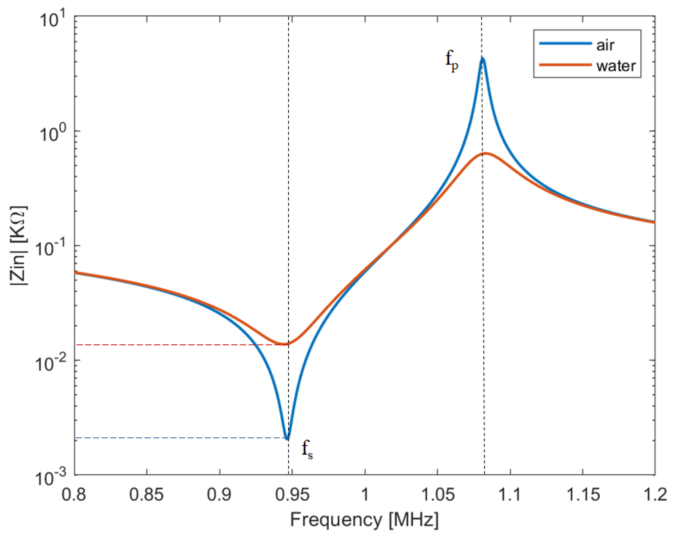
Figure 3.
Schematic structures of micromachined ultrasound transducers: (a) capacitive micromachined ultrasonic transducer (CMUT) cell: the flexural vibration of the membrane is generated by a bias voltage and an alternate signal; (b) piezoelectric micromachined ultrasonic transducers (PMUT) cell: the membrane is composed of at least one piezoelectric layer and one passive elastic layer and the flexural motion is generated by applying only an alternating voltage [55].

Figure 4.
A fingerprint collected by scanning a linear CMUT array along the elevation direction: (a) 3D voxel representation, (b) 2D image extracted at an under-skin depth of 0.2 mm. In both images, sweat pores are clearly visible. Reprinted with permission from [68].
Figure 4.
A fingerprint collected by scanning a linear CMUT array along the elevation direction: (a) 3D voxel representation, (b) 2D image extracted at an under-skin depth of 0.2 mm. In both images, sweat pores are clearly visible. Reprinted with permission from [68].
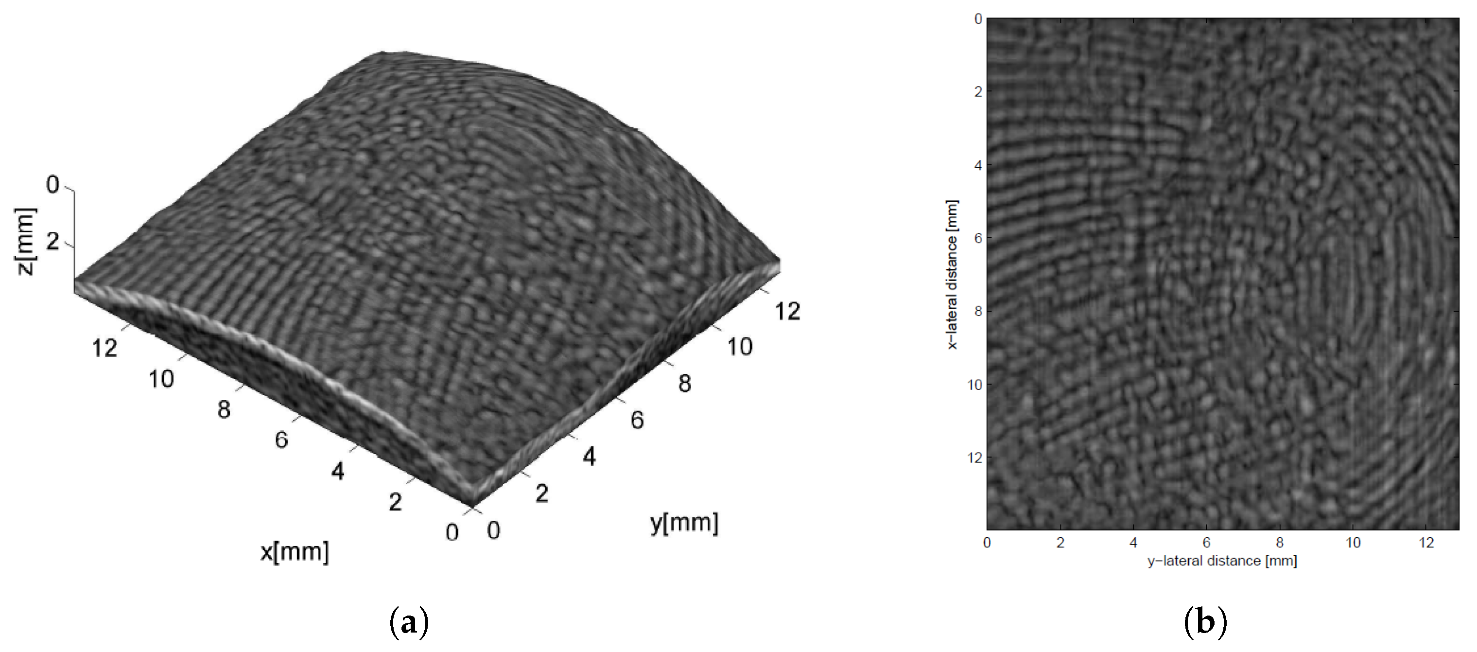
Figure 5.
Example of a palm vein pattern collected through power Doppler analysis: (a) 2D pattern and (b) 3D pattern, which provides improved distinctiveness. Reprinted with permission from [88].
Figure 5.
Example of a palm vein pattern collected through power Doppler analysis: (a) 2D pattern and (b) 3D pattern, which provides improved distinctiveness. Reprinted with permission from [88].

Figure 6.
3D palmprint: (a) a 3D render of a human palm where palm curvature can be appreciated and (b) 3D template accounting for lines’ depth. Reprinted with permission from [95].
Figure 6.
3D palmprint: (a) a 3D render of a human palm where palm curvature can be appreciated and (b) 3D template accounting for lines’ depth. Reprinted with permission from [95].

© 2019 by the author. Licensee MDPI, Basel, Switzerland. This article is an open access article distributed under the terms and conditions of the Creative Commons Attribution (CC BY) license (http://creativecommons.org/licenses/by/4.0/).
Share and Cite
MDPI and ACS Style
Iula, A. Ultrasound Systems for Biometric Recognition. Sensors 2019, 19, 2317. https://doi.org/10.3390/s19102317
AMA Style
Iula A. Ultrasound Systems for Biometric Recognition. Sensors. 2019; 19(10):2317. https://doi.org/10.3390/s19102317
Chicago/Turabian StyleIula, Antonio. 2019. "Ultrasound Systems for Biometric Recognition" Sensors 19, no. 10: 2317. https://doi.org/10.3390/s19102317
Note that from the first issue of 2016, this journal uses article numbers instead of page numbers. See further details here.