
Intelligent RF-Based Gesture Input Devices Implemented Using e-Textiles †


Abstract
:1. Introduction
2. Related Work
3. Approach
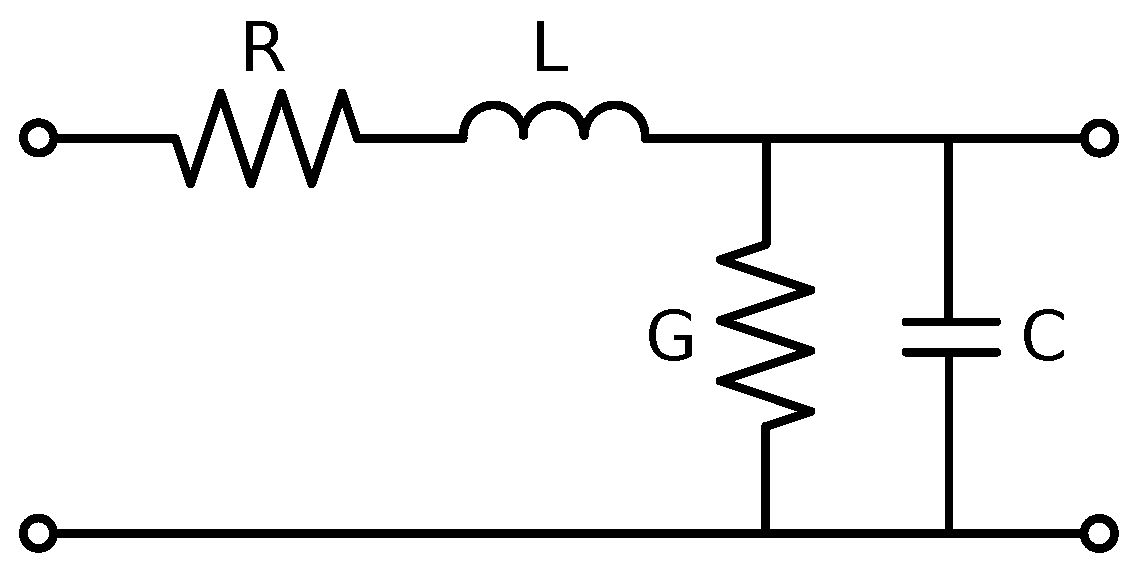
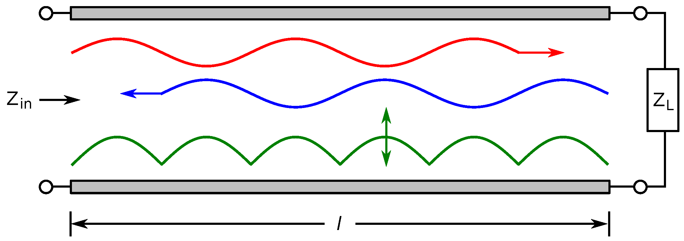
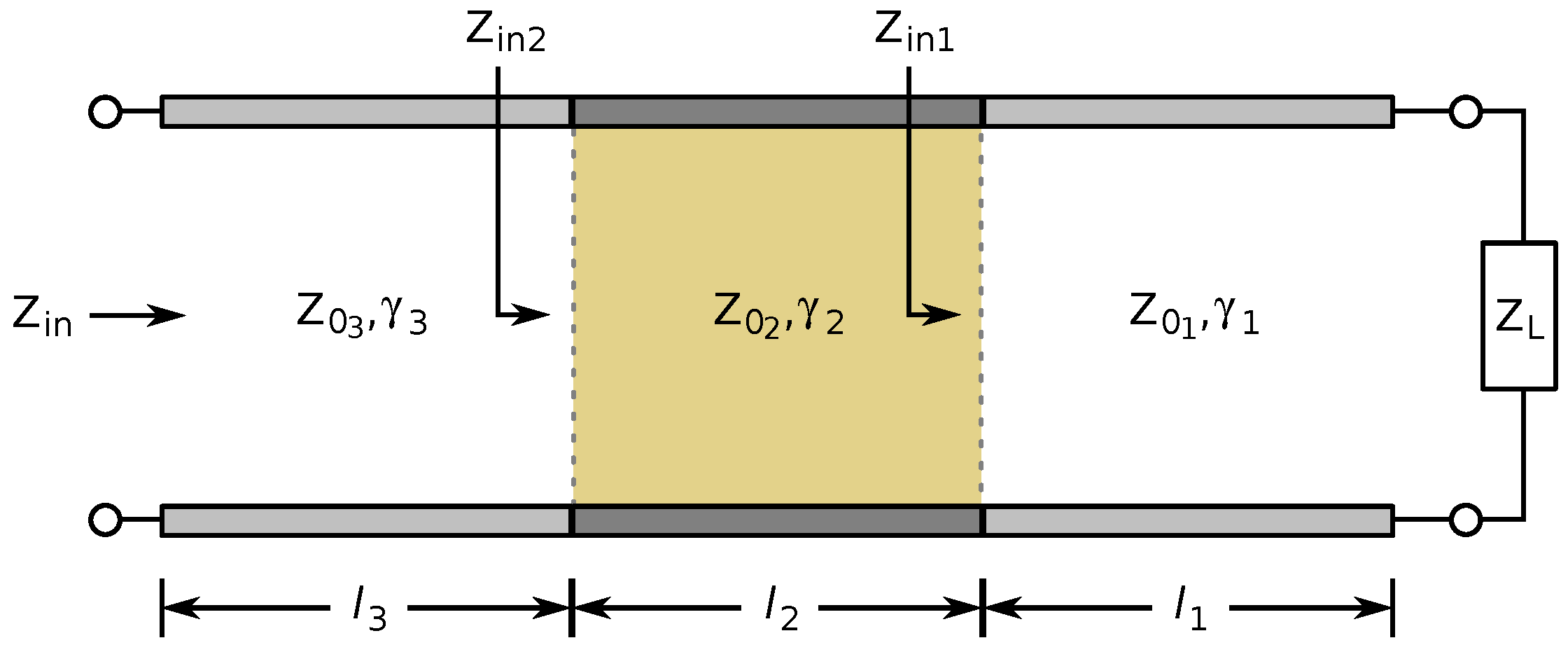
3.1. Transmission Line Theory
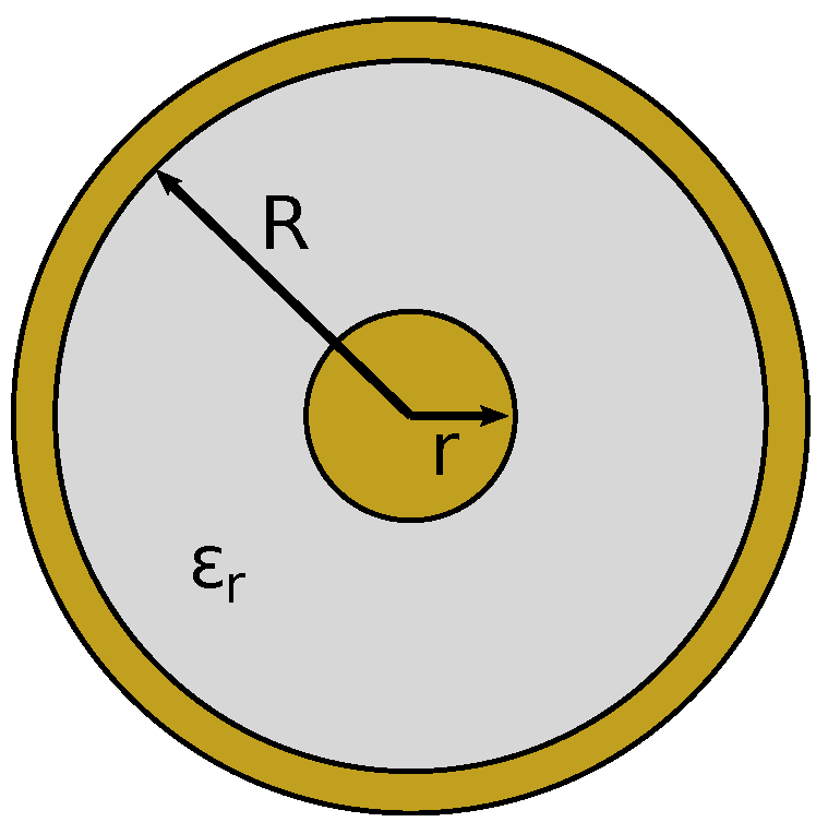
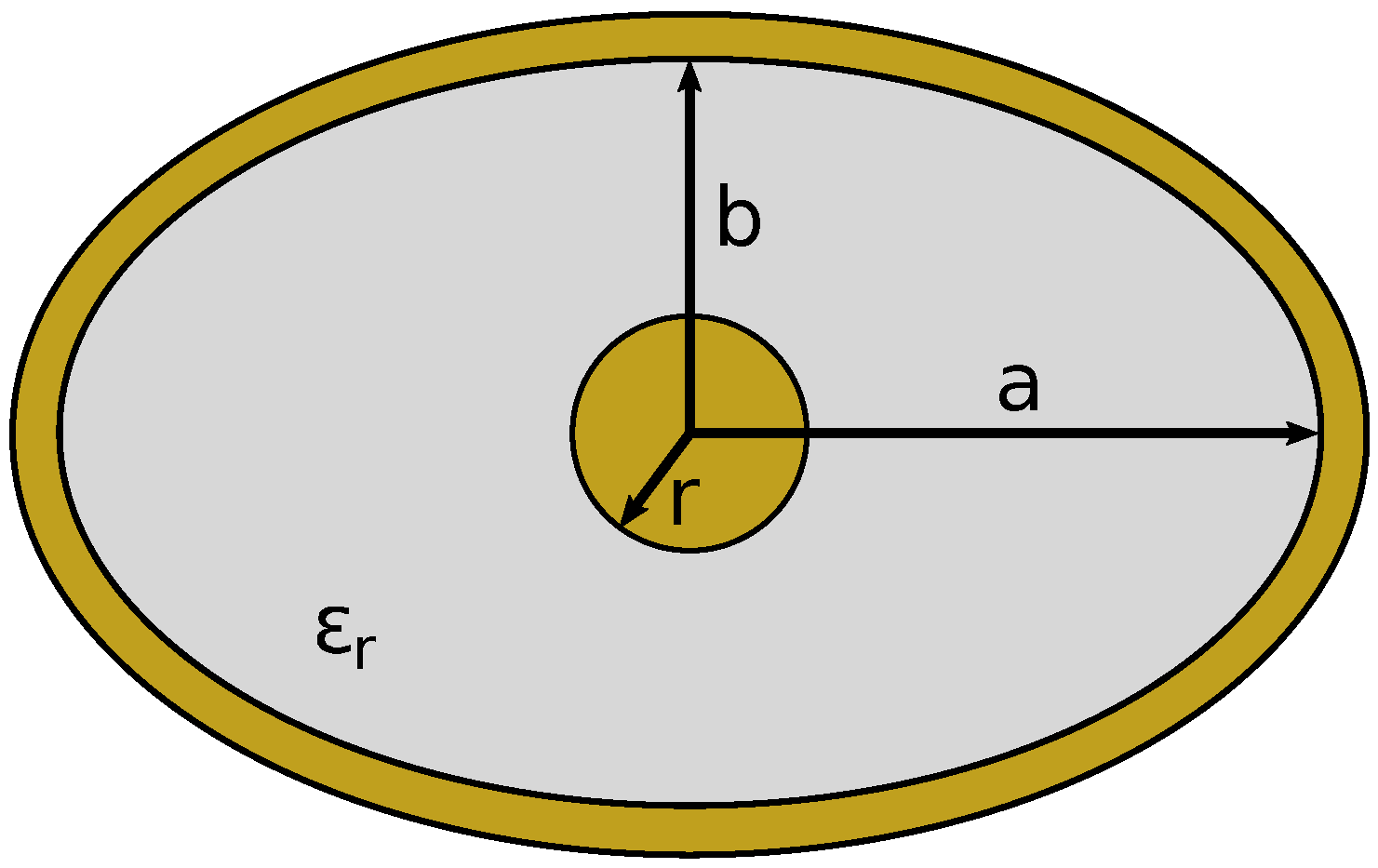
3.1.1. Coaxial
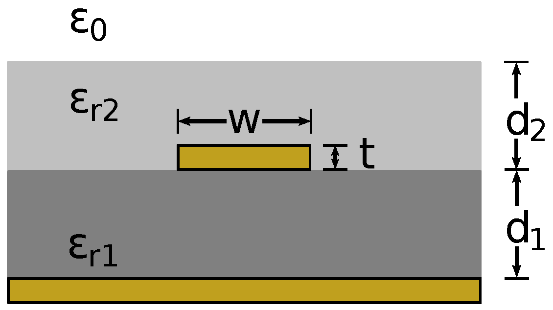
3.1.2. Microstrip
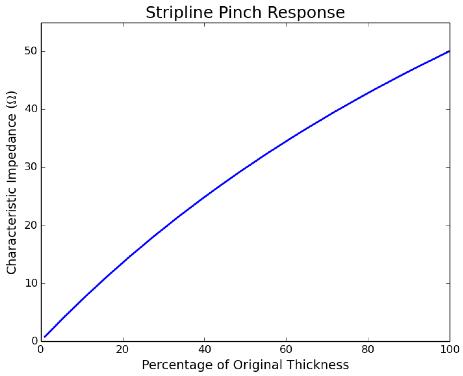
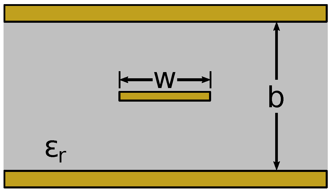
3.1.3. Stripline
4. Simulation Results
4.1. Characteristic Impedances
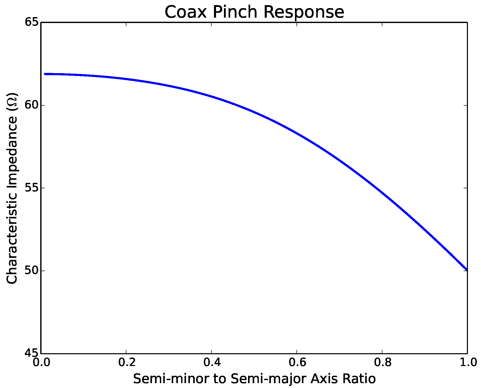
4.1.1. Coaxial Line
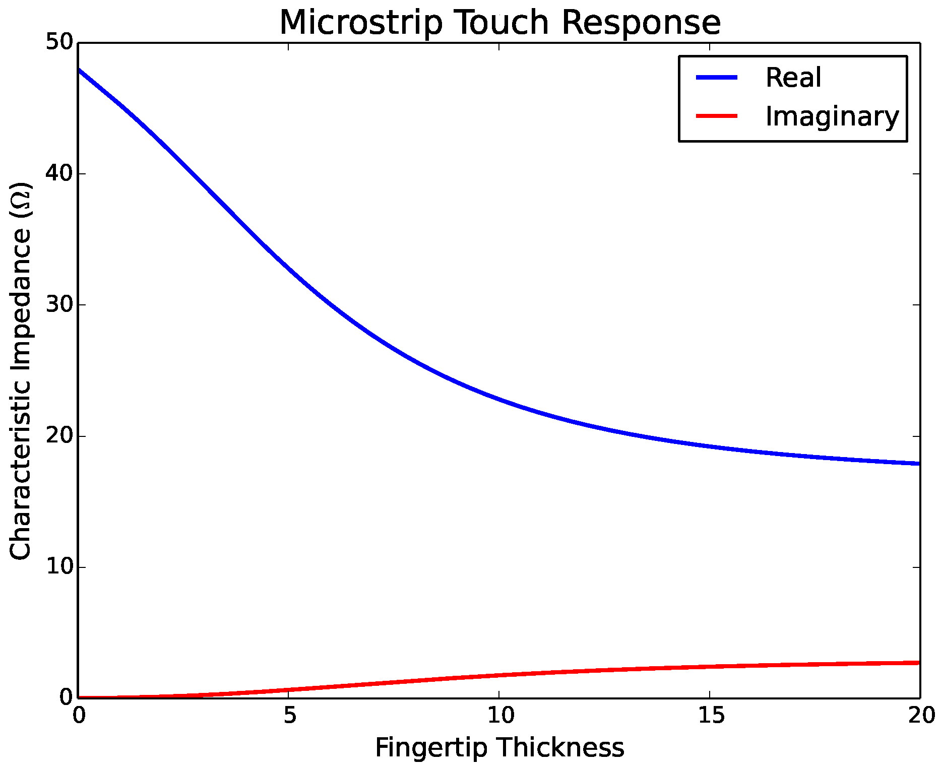
4.1.2. Microstrip
4.1.3. Stripline
4.2. Reflection Coefficient
4.2.1. Coaxial Line
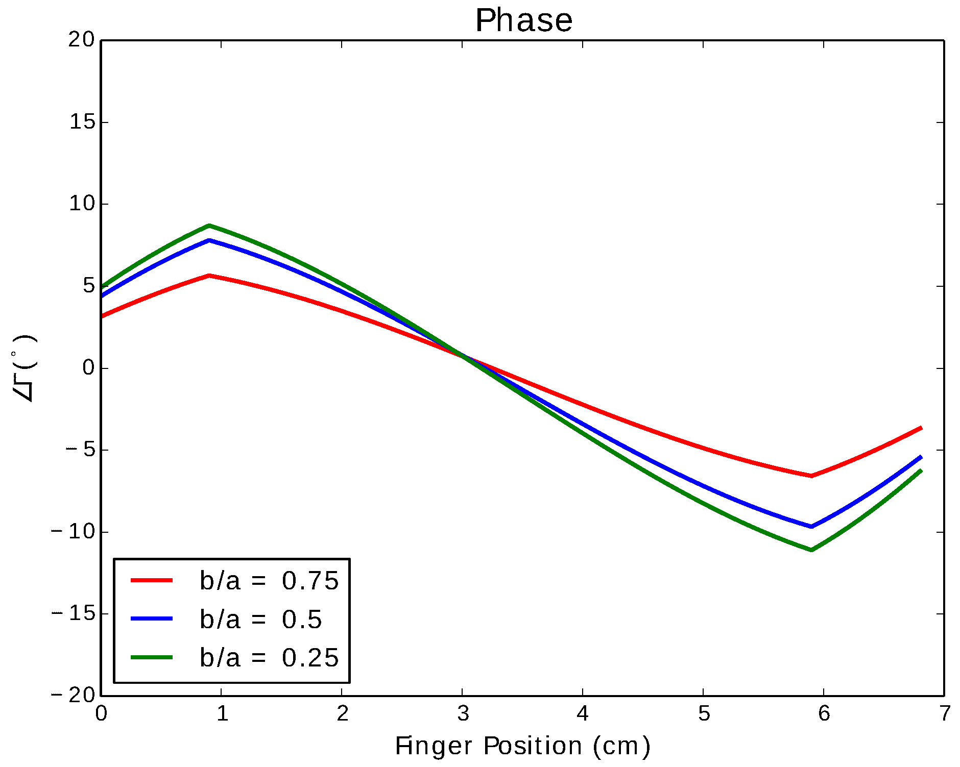
4.2.2. Microstrip
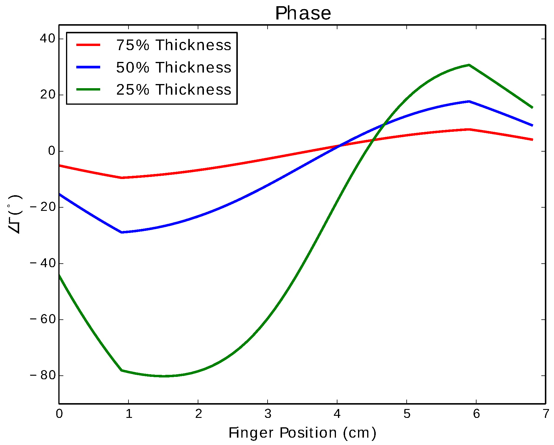
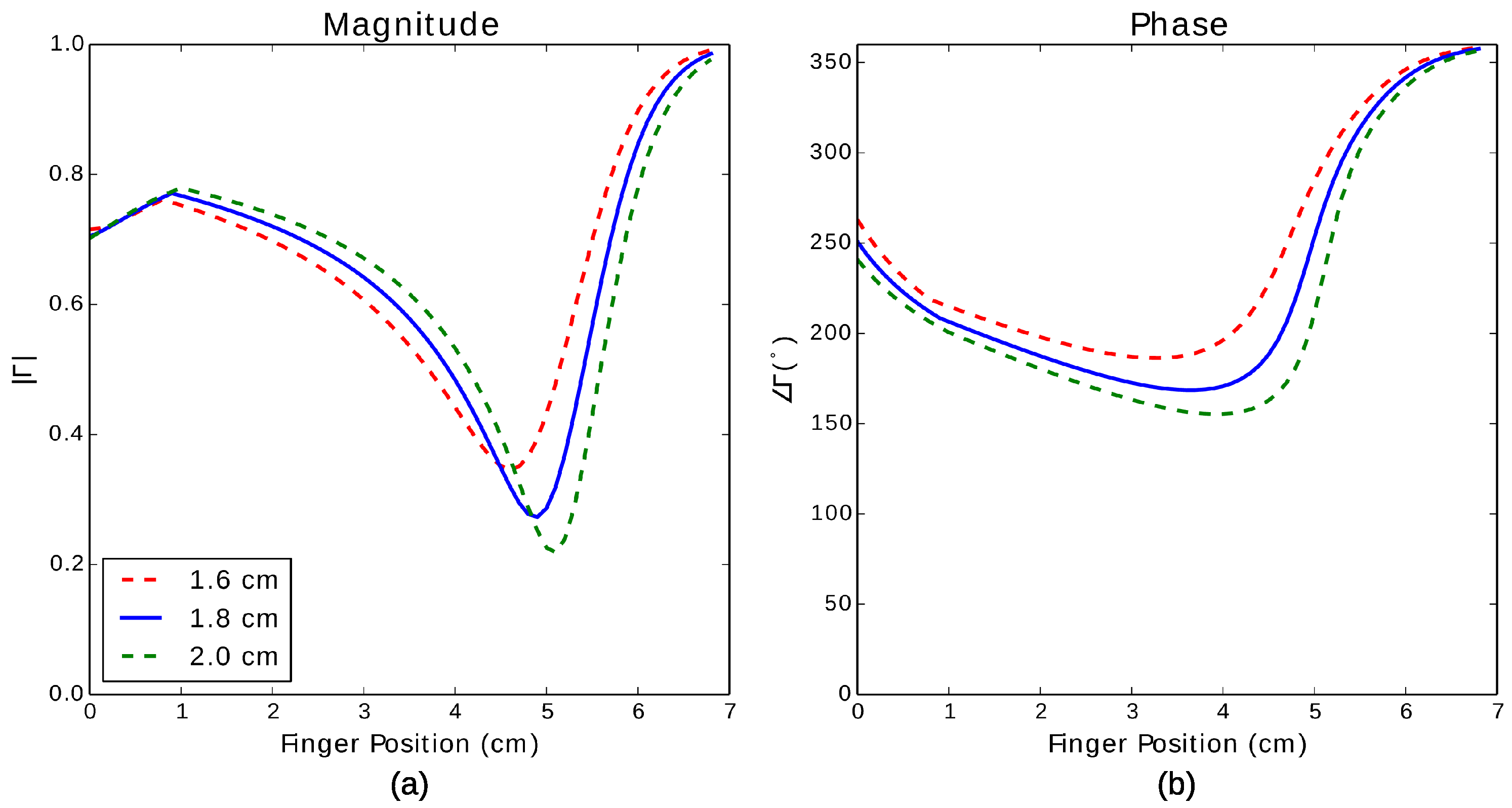
4.2.3. Stripline
4.2.4. Discussion
5. Hardware Implementation
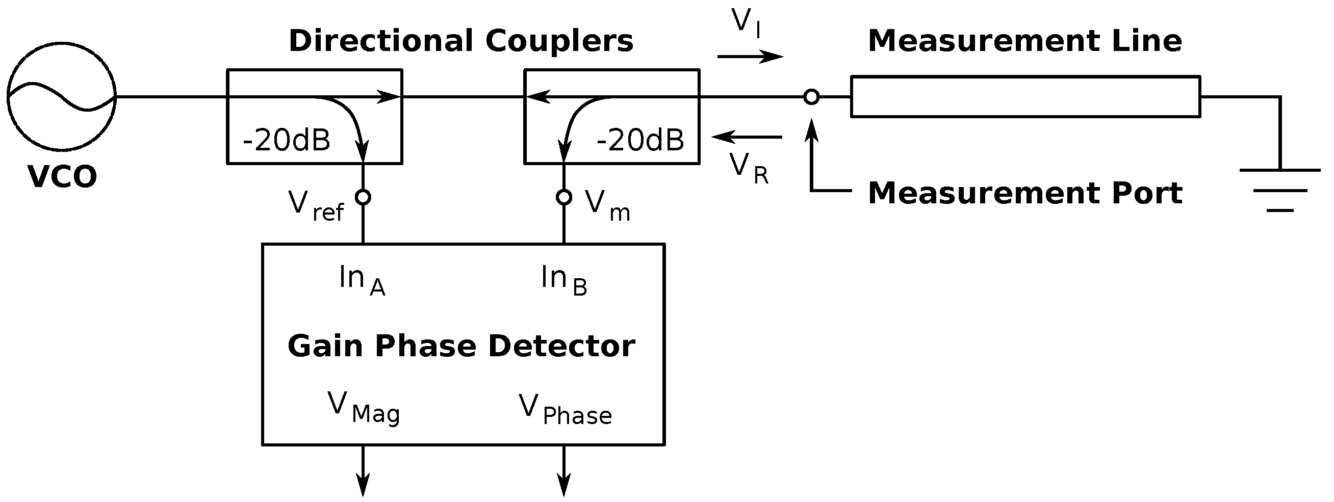
5.1. Reflectometer Circuit
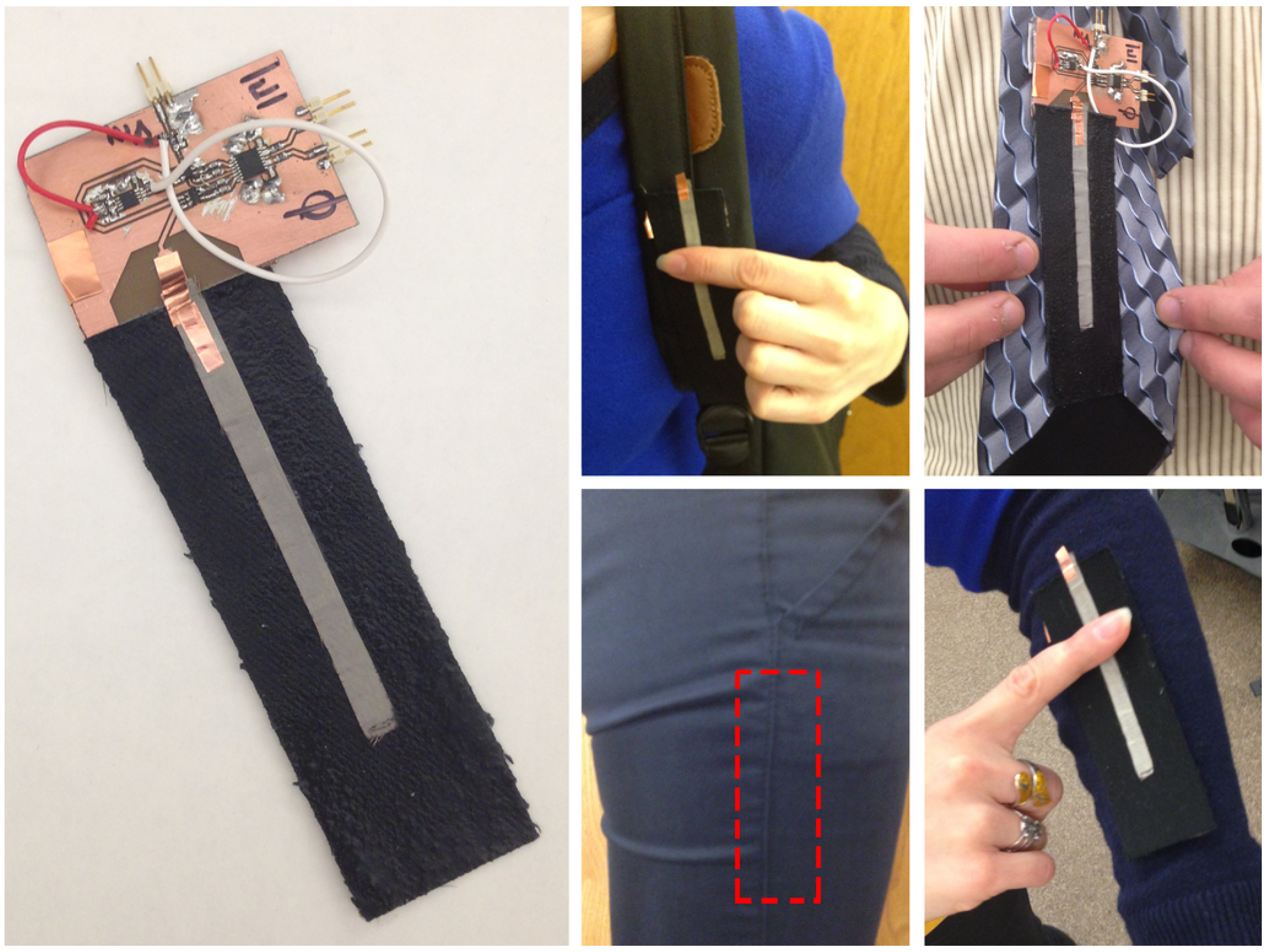
5.2. e-Textile Transmission Lines
6. Gesture Identification
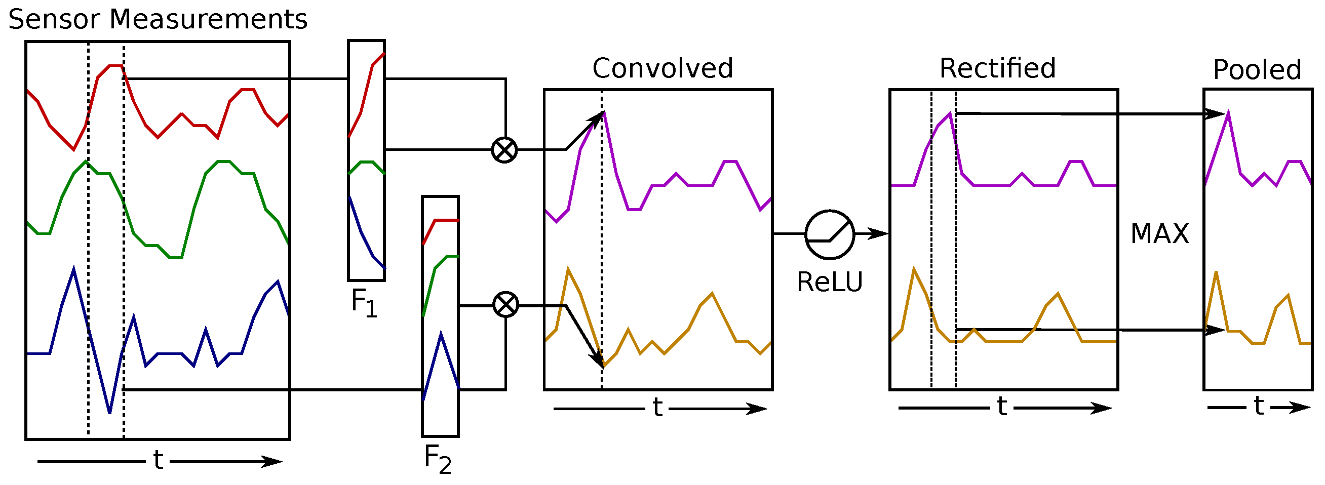
Convolutional Neural Networks
7. Experimental Results
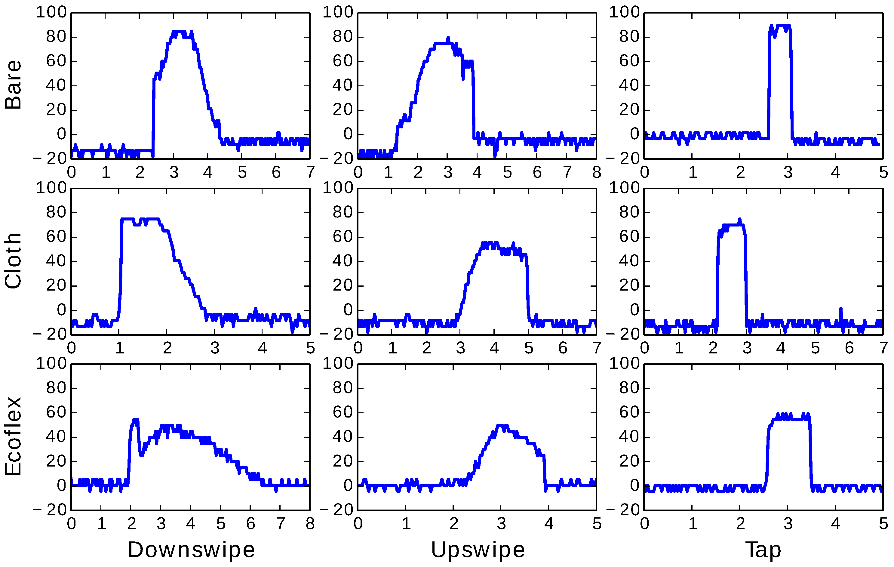
7.1. Sample Gestures
7.2. Gesture Recognition
8. Conclusions
Acknowledgments
Author Contributions
Conflicts of Interest
References
- Post, E.R.; Orth, M. Smart Fabric, or “Wearable Clothing”. In Proceedings of the 1st IEEE International Symposium on Wearable Computers, Montreux, Switzerland, 13–14 October 1997; IEEE: Washington, DC, USA, 1997; pp. 167–168. [Google Scholar]
- Gilliland, S.; Komor, N.; Starner, T.; Zeagler, C. The Textile Interface Swatchbook: Creating Graphical User Interface-like Widgets with Conductive Embroidery. In Proceedings of the International Symposium on Wearable Computers (ISWC), Seoul, Korea, 10–13 October 2010; IEEE: Washington, DC, USA, 2010; pp. 1–8. [Google Scholar]
- Zeagler, C.; Gilliland, S.; Profita, H.; Starner, T. Textile Interfaces: Embroidered Jog-Wheel, Beaded Tilt Sensor, Twisted Pair Ribbon, and Sound Sequins. In Proceedings of the 16th International Symposium on Wearable Computers (ISWC), Newcastle, UK, 18–22 June 2012; IEEE: Washington, DC, USA, 2012; pp. 60–63. [Google Scholar]
- Karrer, T.; Wittenhagen, M.; Lichtschlag, L.; Heller, F.; Borchers, J. Pinstripe: Eyes-free Continuous Input on Interactive Clothing. In Proceedings of the SIGCHI Conference on Human Factors in Computing Systems (CHI’11), Vancouver, BC, Canada, 7–12 May 2011; ACM: New York, NY, USA, 2011; pp. 1313–1322. [Google Scholar]
- Buechley, L.; Eisenberg, M.; Catchen, J.; Crockett, A. The LilyPad Arduino: Using Computational Textils to Investigate Engagement, Aesthetics, and Diversity in Computer Science Education. In Proceedings of the SIGCHI Conference on Human Factors in Computing Systems, Florence, Italy, 5–10 April 2008; ACM: New York, NY, USA, 2008; pp. 423–432. [Google Scholar]
- Holleis, P.; Schmidy, A.; Paasovaara, S.; Puikkonen, A.; Häkkilä, J. Evaluating Capacitive Touch Input on Clothes. In Proceedings of the 10th International Conference on Human Computer Interaction with Mobile Devices and Services (MobileHCI’08), Amsterdam, The Netherlands, 2–5 September 2008; ACM: New York, NY, USA, 2008; pp. 81–90. [Google Scholar]
- Schneegass, S.; Voit, A. GestureSleeve: Using Touch Sensitive Fabrics for Gestural Input on the Forearm for Controlling Smartwatches. In Proceedings of the 2016 ACM International Symposium on Wearable Computers, Heidelberg, Germany, 12–16 September 2016; ACM: New York, NY, USA, 2016; pp. 108–115. [Google Scholar]
- Hughes, D.; Profita, H.; Correll, N. SwitchBack: An On-Body RF-based Gesture Input Device. In Proceedings of the 2014 ACM International Symposium on Wearable Computers, Seattle, WA, USA, 13–17 September 2014; ACM: New York, NY, USA, 2014; pp. 63–66. [Google Scholar]
- Smooth-On Inc. Ecoflex® Series, Super-Soft, Silicone Rubber. Available online: https://www.smooth-on.com/product-line/ecoflex/ (accessed on 25 November 2016).
- McEvoy, M.A.; Correll, N. Materials that Couple Sensing, Actuation, Computation, and Communication. Science 2015, 347. [Google Scholar] [CrossRef] [PubMed]
- Poupyrev, I.; Gong, N.W.; Fukuhara, S.; Karagozler, M.E.; Schwesig, C.; Robinson, K.E. Project Jacquart: Interactive Digital Textiles at Scale. In Proceedings of the 2016 CHI Conferenceon Human Factors in Computing Systems, San Jose, CA, USA, 7–12 May 2016; ACM: New York, NY, USA, 2016; pp. 4216–4227. [Google Scholar]
- Hock, P. Interactive Belt: An Unobtrusive Input Device for Head-Mounted Displays. Master’s Thesis, Universität Ulm, Ulm, Germany, 2015. [Google Scholar]
- Sergio, M.; Manaresi, N.; Tartagni, M.; Guerrieri, R.; Canegally, R. A Textile Based Capacitive Pressure Sensor. In Proceedings of the IEEE on Sensors 2002, Orlando, FL, USA, 12–14 June 2002; IEEE: Washington, DC, USA, 2002; Volume 2, pp. 1625–1630. [Google Scholar]
- Wimmer, R.; Baudisch, P. Modular and Deformable Touch-Sensitive Surfaces Based on Time Domain Reflectometry. In Proceedings of the 24th Annual ACM Symposium on User Interface Software and Technology (UIST’11), Santa Barbara, CA, USA, 16–19 October 2011; ACM: New York, NY, USA, 2011; pp. 517–526. [Google Scholar]
- Sun, S.; Pommerenke, D.J.; Drewniak, J.L.; Chen, G.; Xue, L.; Brower, M.A.; Koledintseva, M.Y. A Novel TDR-Based Coaxial Cable Sensor for Crack/Strain Sensing in Reinforced Concrete Structures. IEEE Trans. Instrum. Meas. 2009, 58, 2714–2725. [Google Scholar]
- Salvado, R.; Loss, C.; Gonçalves, R.; Pinho, P. Textile Materials for the Design of Wearable Antennas: A Survey. Sensors 2012, 12, 15841–15857. [Google Scholar] [CrossRef] [PubMed]
- Salonen, P.; Hurme, L. A Novel Fabric WLAN Antenna for Wearable Applications. In Proceedings of the Antennas and Propagation Society International Symposium, Columbus, OH, USA, 22–27 June 2003; IEEE: Washington, DC, USA, 2003; Volume 2, pp. 700–703. [Google Scholar]
- Osman, M.A.R.; Abd Rahim, M.K.; Samsuri, N.A.; Salim, H.A.M.; Ali, M.F. Embroidered Fully Textile Wearable Antenna for Medical Monitoring Applications. Prog. Electromagn. Res. 2011, 117, 321–337. [Google Scholar] [CrossRef]
- Moradi, E.; Björninen, T.; Ukkonen, L.; Rahmat-Samii, Y. Characterization of Embroidered Dipole-Type RFID Tag Antennas. In Proceedings of the 2012 IEEE International Conference on RFID-Technologies and Applications (RFID-TA), Nice, France, 5–7 November 2012; IEEE: Washington, DC, USA, 2012; pp. 248–253. [Google Scholar]
- Cottet, D.; Grzyb, J.; Kirstein, T.; Troster, G. Electrical characterization of textile transmission lines. IEEE Trans. Adv. Packag. 2003, 26, 182–190. [Google Scholar] [CrossRef]
- Gaspar, D.; Moreira, A.A. Belt Antenna for Wearable Applications. In Proceedings of the IEEE Antennas and Propagation Society International Symposium (APSURsi 2009), Charleston, NC, USA, 1–5 June 2009; IEEE: Washington, DC, USA, 2009; pp. 1–4. [Google Scholar]
- Zhu, S.; Langley, R. Dual-Band Wearable Textile Antenna on an EBG Substrate. IEEE Trans. Antennas Propag. 2009, 57, 926–935. [Google Scholar] [CrossRef]
- Pozar, D.M. Microwave Engineering; John Wiley & Sons, Inc.: Hoboken, NJ, USA, 2012. [Google Scholar]
- Hughes, D.; Correll, N. Texture Recognition and Localization in Amorphous Robotic Skin. Bioinspir. Biomimetics 2015, 10, 055002. [Google Scholar] [CrossRef] [PubMed]
- Hughes, D.; Farrow, N.; Profita, H.; Correll, N. Detecting and Identifying Tactile Gestures using Deep Autoencoders, Geometric Moments and Gesture Level Features. In Proceedings of the 2015 ACM on International Conference on Multimodal Interaction, Santa Monica, CA, USA, 9–13 November 2015; ACM: New York, NY, USA, 2015; pp. 415–422. [Google Scholar]
- Hughes, D.; Correll, N. Distributed Convolutional Neural Networks for Human Activity Recognition in Wearable Robotics. In Proceedings of the 13th International Symposium on Distributed Autonomous Robotic Systems, London, UK, 7–9 November 2016.
- Hughes, D.; Correll, N. Distributed Machine Learning in Materials that Couple Sensing, Actuation, Computation and Communication. arXiv, 2016; preprint. arXiv:1606.03508. [Google Scholar]
- Pan, S.G. Characteristic Impedance of a Coaxial System Consisting of Circular and Noncircular Conductors. IEEE Trans. Microw. Theory Tech. 1998, 36, 917–921. [Google Scholar] [CrossRef]
- Pan, S.G. Approximate Determination of the Characteristic Impedance of the Coaxial System Consisting of an Irregular Outer Conductor and a Circular Inner Conductor. IEEE Trans. Microw. Theory Tech. 1987, 35, 61–63. [Google Scholar]
- Wheeler, H.A. Transmission-Line Properties of a Strip on a Dielectric Sheet on a Plane. IEEE Trans. Microw. Theory Tech. 1977, 25, 631–647. [Google Scholar] [CrossRef]
- Svacina, J. Analysis of multilayer microstrip lines by a conformal mapping method. IEEE Trans. Microw. Theory Tech. 1992, 40, 769–772. [Google Scholar] [CrossRef]
- Sankaralingam, S.; Gupta, B. Determination of dielectric constant of fabric materials and their use as substrates for design and development of antennas for wearable applications. IEEE Trans. Instrum. Meas. 2010, 59, 3122–3130. [Google Scholar] [CrossRef]
- Grant, J.P.; Clarke, R.N.; Symm, G.T.; Spyrou, N.M. In Vivo Dielectric Properties of Human Skin from 50 MHz to 2.0 GHz. Phys. Med. Biol. 1988, 33, 607–612. [Google Scholar] [CrossRef] [PubMed]
- Dandekar, K.; Raju, B.I.; Srinivasan, M.A. 3-D Finite-Element Models of Human and Monkey Fingertips to Investigate the Mechanics of Tactile Sense. J. Biomech. Eng. 2003, 125, 682–691. [Google Scholar] [CrossRef] [PubMed]
- Takamatsu, S.; Kobayashi, T.; Shibayama, N.; Miyake, K.; Itoh, T. Fabric Pressure Sensor Array Fabricated with Die-Coating and Weaving Techniques. Sens. Actuators A Phys. 2012, 184, 57–63. [Google Scholar] [CrossRef]
- Hoer, C. A Network Analyzer Incorporating Two Six-Port Reflectometers. IEEE Trans. Microw. Theory Tech. 1977, 25, 1070–1074. [Google Scholar] [CrossRef]
- Hoffmann, K.; Škvor, Z. A Novel Vector Network Analyzer. IEEE Trans. Microw. Theory Tech. 1998, 46, 2520–2523. [Google Scholar] [CrossRef]
- Abou-Khousa, M.A.; Baumgartner, M.A.; Kharkovsky, S.; Zoughi, R. Novel and Simple High-Frequency Single-Port Vector Network Analyzer. IEEE Trans. Instrum. Meas. 2010, 59, 534–542. [Google Scholar] [CrossRef]
- Fallahpour, M.; Baumgartner, M.A.; Kothari, A.; Ghasr, M.T.; Pommerenke, D.; Zoughi, R. Compact Ka-Band One-Port Vector Reflectometer Using a Wideband Electronically Controlled Phase Shifter. IEEE Trans. Instrum. Meas. 2012, 61, 2807–2816. [Google Scholar] [CrossRef]
- Monolithic Voltage-Controlled Oscillators. Available online: http://datasheets.maximintegrated.com/en/ds/MAX2622-MAX2624.pdf (accessed on 20 January 2017).
- DC09-73LF: Directional Coupler 0.81–0.96 GHz. Available online: http://www.skyworksinc.com/uploads/documents/DC09_73LF_200228C.pdf (accessed on 20 January 2017).
- LF–2.7 GHz RF/IF Gain and Phase Detector. Available online: http://www.analog.com/static/imported-files/data_sheets/AD8302.pdf (accessed on 20 January 2017).
- Conductive Fabric - 12“x13” Ripstop. Available online: https://www.sparkfun.com/products/10056 (accessed on 20 January 2017).
- Conductive Thread - 117/17 2Ply. Available online: https://www.sparkfun.com/products/retired/8544 (accessed on 20 January 2017).
- LeCun, Y.; Bengio, Y. Convolutional networks for images, speech, and time series. Handb. Brain Theory Neural Netw. 1995, 3361, 276–279. [Google Scholar]
- Abadi, M.; Agarwal, A.; Barham, P.; Brevdo, E.; Chen, Z.; Citro, C.; Corrado, G.S.; Davis, A.; Dean, J.; Devin, M.; et al. TensorFlow: Large-Scale Machine Learning on Heterogeneous Systems, 2015. Available online: tensorflow.org (accessed on 20 January 2017).
- Kingam, D.P.; Ba, J.L. Adam: A Method for Stochastic Optimization. arXiv, 2014; preprint. arXiv:1412.6980. [Google Scholar]


| Fingertip Width | γ (rad/m) | ||
|---|---|---|---|
| Untouched | |||
| 1.6 cm | |||
| 1.8 cm | |||
| 2.0 cm |
| Predicted | ||||
|---|---|---|---|---|
| Tap | Up Swipe | Down Swipe | ||
| Actual | Tap | 113 | 3 | 4 |
| Up swipe | 1 | 118 | 1 | |
| Down swipe | 4 | 1 | 115 | |
© 2017 by the authors. Licensee MDPI, Basel, Switzerland. This article is an open access article distributed under the terms and conditions of the Creative Commons Attribution (CC BY) license ( http://creativecommons.org/licenses/by/4.0/).
Share and Cite
Hughes, D.; Profita, H.; Radzihovsky, S.; Correll, N. Intelligent RF-Based Gesture Input Devices Implemented Using e-Textiles. Sensors 2017, 17, 219. https://doi.org/10.3390/s17020219
Hughes D, Profita H, Radzihovsky S, Correll N. Intelligent RF-Based Gesture Input Devices Implemented Using e-Textiles. Sensors. 2017; 17(2):219. https://doi.org/10.3390/s17020219
Chicago/Turabian StyleHughes, Dana, Halley Profita, Sarah Radzihovsky, and Nikolaus Correll. 2017. "Intelligent RF-Based Gesture Input Devices Implemented Using e-Textiles" Sensors 17, no. 2: 219. https://doi.org/10.3390/s17020219
APA StyleHughes, D., Profita, H., Radzihovsky, S., & Correll, N. (2017). Intelligent RF-Based Gesture Input Devices Implemented Using e-Textiles. Sensors, 17(2), 219. https://doi.org/10.3390/s17020219