PSpice Modeling of a Sandwich Piezoelectric Ceramic Ultrasonic Transducer in Longitudinal Vibration


Department of Electronic Engineering, Xi’an University of Technology, Xi’an 710048, Shaanxi, China
*
Author to whom correspondence should be addressed.
Sensors 2017, 17(10), 2253; https://doi.org/10.3390/s17102253
Submission received: 31 August 2017
/
Revised: 23 September 2017
/
Accepted: 28 September 2017
/
Published: 30 September 2017
(This article belongs to the Section Physical Sensors)
Abstract
:Sandwiched piezoelectric transducers are widely used, especially in high power applications. For more convenient analysis and design, a PSpice lossy model of sandwiched piezoelectric ultrasonic transducers in longitudinal vibration is proposed by means of the one-dimensional wave and transmission line theories. With the proposed model, the resonance and antiresonance frequencies are obtained, and it is shown that the simulations and measurements have good consistency. For the purpose of further verification the accuracy and application of the PSpice model, a pitch-catch setup and an experimental platform are built. They include two sandwiched piezoelectric ultrasonic transducers and two aluminum cylinders whose lengths are 20 mm and 100 mm respectively. Based on this pitch-catch setup, the impedance and transient analysis are performed. Compared with the measured results, it is shown that the simulated results have good consistency. In addition, the conclusion can be drawn that the optimal excitation frequency for the pitch-catch setup is not necessarily the resonance frequency of ultrasonic transducers, because the resonance frequency is obtained under no load. The proposed PSpice model of the sandwiched piezoelectric transducer is more conveniently applied to combine with other circuits such as driving circuits, filters, amplifiers, and so on.
1. Introduction
The sandwiched piezoelectric ultrasonic transducer vibrating in longitudinal mode is also called the Langevin composite transducer. It consists of metal front and back masses, piezoelectric ceramic stack, metal electrodes and the prestressed bolt. Based on the conventional design theory about the sandwiched piezoelectric transducers vibrating in longitudinal mode as shown in Figure 1, it is required that the diameter be smaller than its longitudinal dimension, in order that the one-dimensional longitudinal vibration theory be applied [1]. It is regarded as a fundamental component in various ultrasonic applications [1,2,3], and is widely used in high power ultrasonic fields including ultrasonic detecting, ultrasonic welding, underwater sound communication, and so on. Moreover, it has some advantages such as high-power capacity, high electro-acoustic conversion efficiency, low losses in mechanical and dielectric, and so on.
It is well known that the theory analysis for piezoelectric components is a vital basis for the design of piezoelectric transducers. So far there are a few methods used in analyzing piezoelectric transducers. Among the methods, the equivalent circuit method is widely used, because it is brief and clear in its physical meaning. In addition, mechanical and dielectric losses can be easily taken into account using the equivalent circuit method. The piezoelectric ceramic disks or rings vibrating in the thickness direction have been successfully modeled by using equivalent circuit methods which mainly include Mason’s [4], Redwood’s [5] and Krimholtz Leedom Matthaei (KLM) models [6]. In order to achieve these equivalent circuits mentioned above on the circuit analysis softwares such as PSpice and Spice, many efforts have been made [7,8]. In view of the circuit models mentioned above containing negative capacitance and transformer, based on the controlled sources and the lossless transmission line, an elegant equivalent circuit model for piezoelectric ceramic disks or rings vibrating in the thickness direction is proposed by Leach [9]. Then the simulation program with integrated circuit emphasis (SPICE) equivalent circuit model was proposed by Puttmer A. [10] to investigate the effect of the losses in mechanical and dielectric. Van D.J. et al. [11] used the approach of Puttmer A. et al. [10] to investigate the speed of acoustic and attenuation in solids and liquids. Guisado A. et al. [12] applied the Leach’s model to obtain the most accurate equivalent circuit of piezoceramic vibrating in thickness mode by using PSpice. The above published works aimed at obtaining some material acoustic parameters and the accurate equivalent circuit based on a single piezoelectric ceramic ring or disk vibrating in the thickness direction.
For the sandwiched piezoelectric ultrasonic transducer form in Figure 1, it has been researched based on Mason’s model by Lin S.Y. et al. from the perspective of theory analysis [13,14,15]. But with this method it is not easy to combine with some circuits such as excitation circuits, filters and amplifiers, diodes, and so on. Also, the required parameters cannot be got easily, which primarily includes resonance and anti-resonance frequencies, the input electrical impedance and phase, input reactance, and the mass vibrating speed. Therefore, in order to solve these problems above, by means of the SPICE equivalent circuit model [10], a PSpice equivalent circuit model of the sandwiched piezoelectric ultrasonic transducer vibrating in longitudinal mode is given in this paper. Based on the proposed PSpice model, the impedance and transient analysis are performed so as to obtain the resonance and anti-resonance frequencies, the vibrating speed ratio between the front mass and the back mass. For further verification of the accuracy and application of the proposed PSpice model, a pitch-catch setup and an experimental platform are built. The analysis in time and frequency domains is carried out by the pitch-catch setup. It can be found that the simulated results have good consistency with the experimental ones.
2. Materials and Methods
For establishing the PSpice model of the sandwich piezoelectric ultrasonic transducer vibrating in longitudinal direction, the one-dimensional wave and transmission line theories for the piezoelectric vibrational mechanism in thickness mode are illustrated in this section.
2.1. Transmission Line and Wave Theories
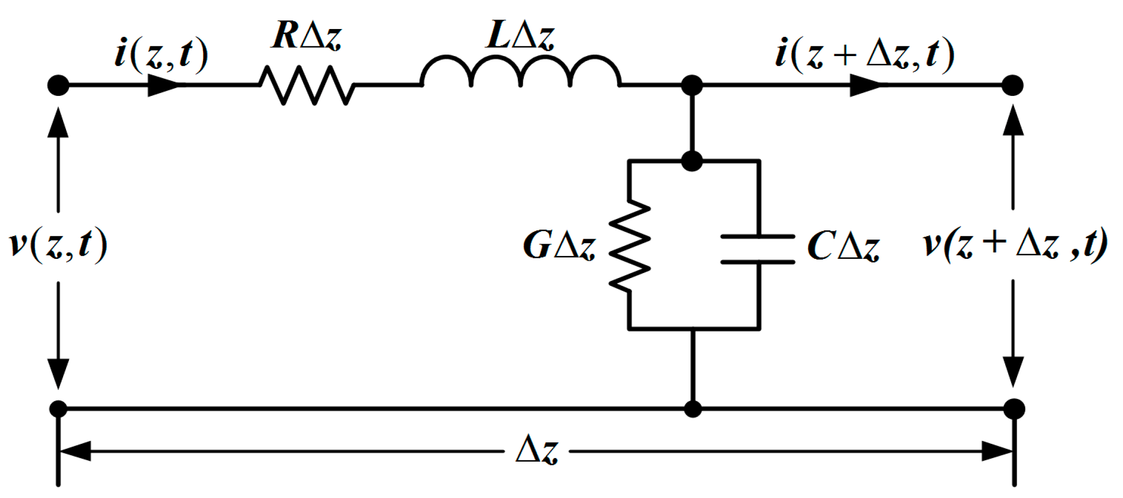
To obtain the proper parameters used in simulations, the comparison of wave propagation is carried out in electrical transmission lines and acoustical medium, respectively. Consider a different length of a transmission line from Figure 2, which is illustrated by the parameters as follows [16]:
- represents the resistance per unit length in ,
- represents the inductance per unit length in ,
- represents the conductance per unit length in ,
- represents the capacitance per unit length in .
Note that and are connected in series, and are connected in parallel.
To obtain the above parameters, Kirchhoff’s voltage law is used in the circuit from Figure 2, we have
which leads to
With the limit as , Equation (2) becomes
Similarly, by using Krichhoff’s current law to the node in Figure 2, we can derive
Then letting , we can obtain
We call Equations (3) and (5) the general transmission-line equations, which are first-order partial differential equations based on and . For simplifying the pair partial differential equations, the time harmonic cosine function is used and the voltage and the current can be expressed as
where is the angular frequency.
The general transmission line equations on the basis of and can be obtained
Equations (8) and (9) are called as time-harmonic transmission line equations which simplify to the following Equations (10) and (11) under the lossless conditions (, ).
In order to obtain the propagation constant and characteristic impedance of transmission line, the time-harmonic transmission line equations are used. By means of differentiating them with respect to , we can obtain [16]
where is called as the propagation constant. It is composed of an attenuation constant in and a phase constant in . It can be expressed as
The general solution of the differential Equation (12) is denoted as
and Equation (13) has the same form solution.
The time dependence for Equation (15) can be got by means of multiplying , we can obtain
Equation (16) illustrates two traveling waves. One travels in the positive direction with an amplitude and it decays at a rate , while the other travels in the opposite direction with an amplitude and has the same decay-rate. The propagation of an acoustical wave is controlled by a pair of differential equations which have the same type as Equations (12) and (13). In the situation of harmonic waves, corresponding with Equations (12) and (13), the linearized acoustic plane wave with lossy Equations can be obtained [17]:
here, is called the pressure in and represents the particle velocity in . Corresponding to , denotes also the complex wave number consisted of an attenuation constant in and a wave number in . The complex wave-number can be expressed as
here, is the relaxation time and is the sound speed, represents Young’s modulus and is material density.
The general solution for Equation (17) is expressed as
and is corresponding with the electrical transmission line’s solution Equation (16). In addition, Equation (18) has a solution of the same form. Combined with Equations (19) and (20), we can derive
The characteristic impedance of the lossy transmission line is given as [16]
The characteristic acoustic impedance of the lossy acoustical medium is represented as
here, denotes the medium’s density in . Equations (23) and (14) are expanded in order to approximate the characteristic impedance and propagation constant by reserving the low order parts. They are rewritten as
Now we take small but non-negligible losses into consideration and suppose , and . Based on these assumptions, the second term of Equation (25) is neglected, only keeping the as the characteristic impedance. Likewise, according to Equation (24), the low acoustical characteristic impedance is derived as . In addition, the wave-number to Equation (22) can be approximately expressed as . By using the approximate assumptions mentioned above again, according to Equation (26) the phase constant can be obtained as . For the purpose of correlating the two theories, the impedance type analogy relationship is selected in which the mechanical force is denoted by the voltage and the current denotes particle velocity. The equivalence between the systems is denoted as
here, is the cross-sectional area for the acoustic beam in .
The relationship of the low-loss characteristic impedance Equation (27) is used to obtain the following expressions
The real part of Equation (26) is called as the attenuation constant as follows:
Corresponding to Equation (30), the classical theory relationship of acoustic attenuation is obtained as
here, denotes the attenuation coefficient resulting from viscous losses while is the attenuation coefficient deriving from the thermal conduction.
According to Equations (28)–(30), we can derive the following expressions
Because of the materials used in the sandwich piezoelectric ultrasonic transducer having a low heat conductance, the loss resulting from the thermal conductance can be neglected. Then letting the conductance , we can get
here, is mechanical loss factor and is mechanical quality factor.
Therefore, Equation (32) can be rewritten as
Finally, the parameters of the acoustical lossy transmission line can be derived as follows:
2.2. Piezoelectric Ceramic Ring Vibrating in Thickness Mode
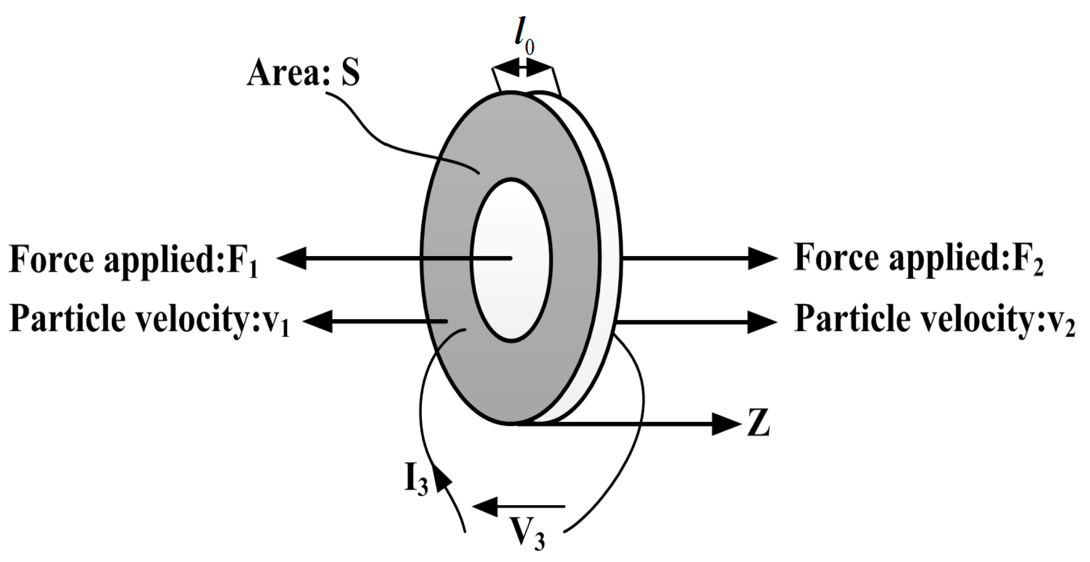
The thickness direction vibration of the thickness poled piezoelectric ceramic rings is a general vibration mode. For this kind of thickness poled piezoelectric ceramic ring, its thickness is much lower than diameter. It is assumed that it works in the thickness mode. For the piezoelectric ring with fixed or free ends vibrating in thickness mode, it has a fundamental resonant frequency [18]:
here, denotes acoustic velocity in piezoelectric material and denotes the thickness of a piezoelectric ceramic ring.
, are the external forces applied to the back and front surfaces of the piezoelectric ceramic ring, is its thickness, indicates its cross-section area, and represent the particle speed, , denotes the voltage and current respectively and the axis indicates the vibrating direction as shown in Figure 3.
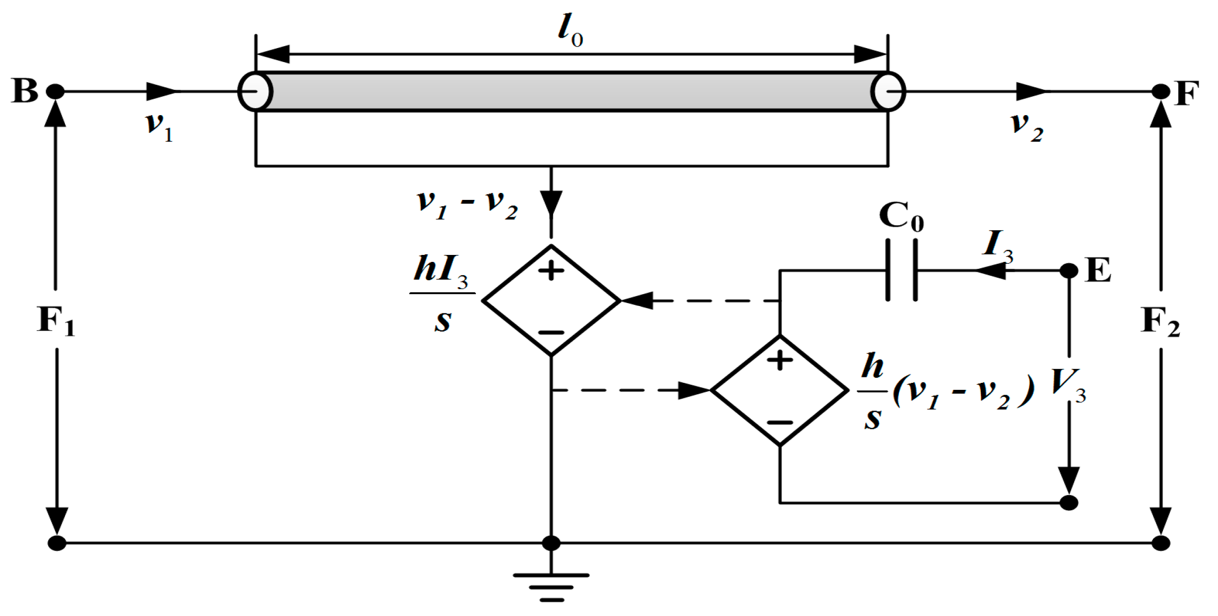
For modeling a sandwiched piezoelectric ceramic transducer vibrating in longitudinal mode, the piezoelectric ring is modeled using Leach’s equivalent circuit model [9] as shown in Figure 4.
It consists of the clamped capacitance , a transmission line used to represent the mechanical parts of the piezoelectric ring, and two controlled sources used for indicating the coupling between the electrical and mechanical sections of the piezoelectric ring. Here, is the piezoelectric constant, is the Laplace operator, the nodes B, E and F represent the back face, the front face and the electrical terminal of the piezoelectric ceramic ring, respectively. For the electrical part, the clamped capacitance is given as follows
here, is the clamped dielectric impermeability, the cross-section area .
3. PSpice Modeling
For establishing the PSpice model of the sandwiched piezoelectric ceramic ultrasonic transducer vibrating in longitudinal direction, the piezoelectric ceramic stack from Figure 1 is modeled using Leach’s equivalent circuit model from Figure 4, and non-piezoelectric elements including the front and back masses, and metal electrodes from Figure 1 are modeled by using the lossless transmission line as shown below.
3.1. Modeling of Non-Piezoelectric Elements
For simplifying the ultrasonic transducer model, the metal front and back masses and metal electrodes are modeled by using the lossless transmission line model from Figure 5.
In the simulation using PSpice, the parameters of the lossless transmission line mainly include the resonance frequency , the normalized length of the transmission line and the characteristic impedance . Then, their expressions are given as [19]:
here, is the material sound velocity, represents the cross-sectional area and denotes the length of the transmission line.
3.2. Modeling of the Piezoelectric Ceramic Stack Vibrating in Longitudinal Direction
The single piezoelectric ceramic ring is modeled using the PSpice model from Figure 6, and the model takes losses including mechanical and dielectric losses into consideration by means of the lossy transmission line and resistance used to represent dielectric loss.
The parameters of the lossy transmission line are obtained from Equation (36), and the loss resistance is given as [20]
here, is called as the dielectric loss factor and is electrical quality factor. Then, resistance [10] has the value and capacitance has the value .
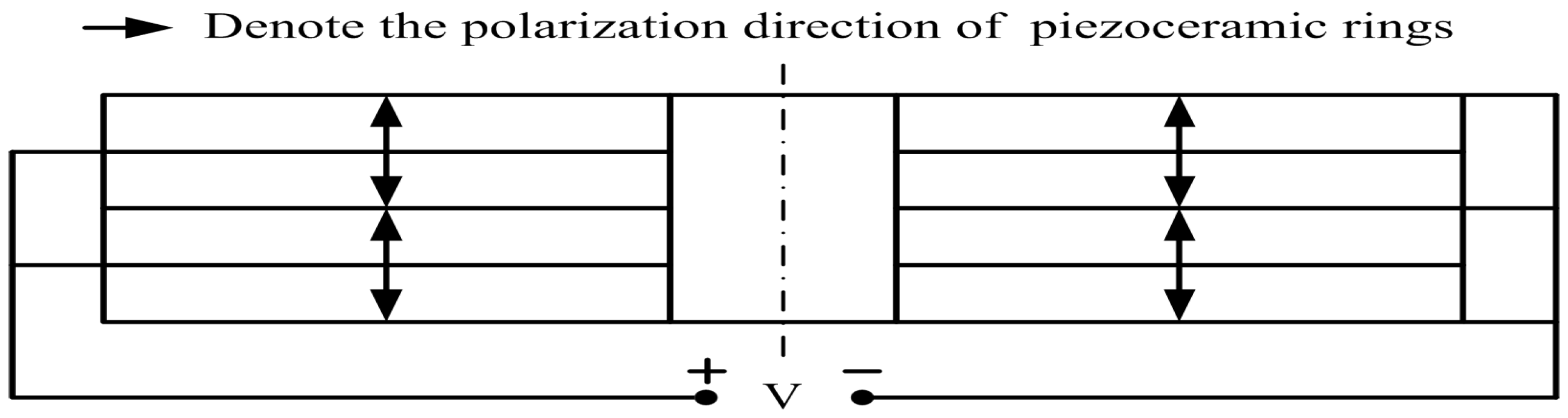
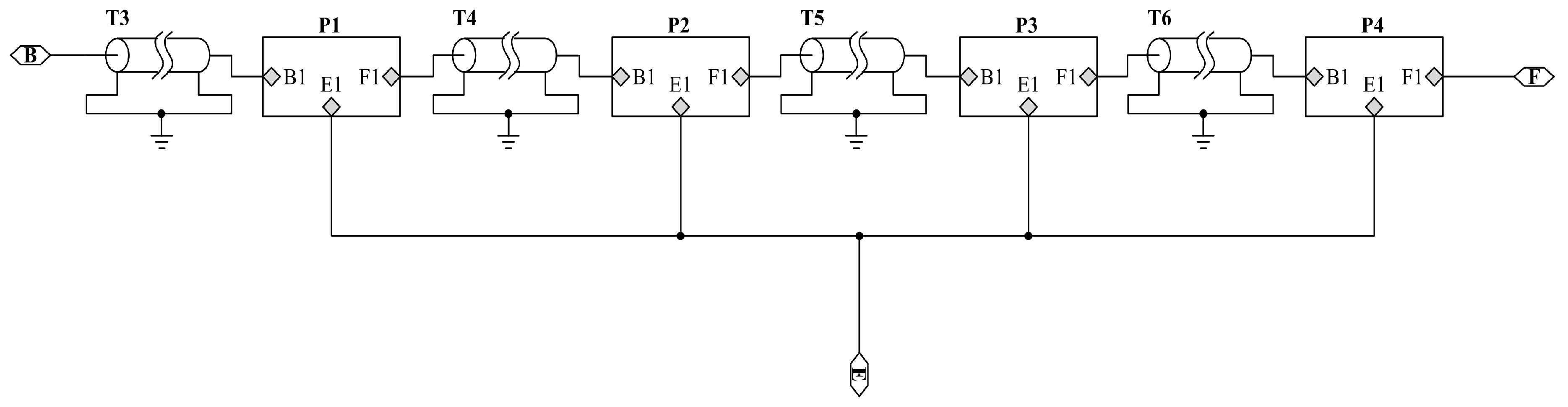
In Figure 7, denotes the voltage. The piezoelectric ceramic stack is composed of four same poled rings and four metal electrodes as shown in Figure 7. Therefore we need four PSpice models of the piezoelectric rings from Figure 6 and four lossless transmission line models from Figure 5 to implement the model of a piezoelectric ceramic stack.
The piezoelectric rings located in the piezoelectric ceramic stack are connected together mechanically in series as shown in Figure 8. However, they belong to parallel relationship in the electrical terminals [21]. Here, T3, T4, T5, T6 are the metal electrodes and P1, P2 and P3, P4 are the piezoelectric ceramic rings.
3.3. The Sandwich Piezoelectric Ultrasonic Transducer Model with PSpice
On the basis of the above analysis about the modeling of the piezoelectric stack and the metal masses, we can obtain the PSpice model of the sandwich piezoelectric ultrasonic transducer from Figure 9.
In Figure 9, the resistances and are used to model air load and have the value [22] . Also, the resistances and are used to represent the bonded layer and have the value . Then the resistance used to model the internal resistance of AC voltage source has the value .
The sandwich piezoelectric ceramic ultrasonic transducer is mentioned in this paper and the piezoelectric material selects PZT-4 [23], and the metal materials [24] used in the front and back masses are hard aluminum and steel, respectively. The detailed parameters of these materials are given in Table 1, Table 2, Table 3 and Table 4. Here, it should be pointed that is the length of the back mass, is the length of the front mass and is the thickness of a metal electrode ring. For the purpose of verification the accuracy of the proposed PSpice model of the piezoelectric ultrasonic transducer, the impedance analysis based on the simulation circuit from Figure 9 is carried out as shown in below.
3.4. Impedance Analysis
The impedance analysis is used to research the frequency response and derive the resonance and antiresonance frequencies. Moreover, the measured impedance results are obtained by utilizing the impedance analyzer PV520A which is made by BEIJING BAND EAR CO (Beijing, China), LTD as shown in Figure 10. The impedance analysis results of the sandwich ultrasonic transducer are shown in Figure 11. The resonance and anti-resonance frequencies of the measured and simulated are specially shown in Table 5. From Table 5, and represent the simulated and measured frequencies of a sandwich piezoelectric transducer, respectively and . Also, and represent resonance and anti-resonance frequencies, respectively. From Table 5, it can be found that the measured results have good consistency with the simulated results.
There are several factors that can well explain frequency error or difference in frequencies in Table 5. Firstly, the standard physical parameters of the piezoelectric ceramic rings, the metal masses and the metal electrodes are applied in simulation; to a certain extent, they are different from the truthful physical parameters. Secondly, it must be met in the theoretical analysis condition that the length of the sandwiched ultrasonic transducer have to be much more than its diameter, so that the vibration of the sandwiched transducer can be approximated as the longitudinal vibration of an extended composite round bar. However, it is not possible in practical cases. Thirdly, based on the above analysis, the prestressed bolt and the epoxy resin used for sealing the sandwiched transducer are ignored in the proposed PSpice model. Here, it should be pointed out that the prestressed bolt has the effect on the electrical impedance with resulting in some frequency error. In addition, the sealing epoxy resin can lead to some frequency error for it changing the vibrator length. However, for the practical transducers, these will not be neglected.
3.5. Transient Analysis
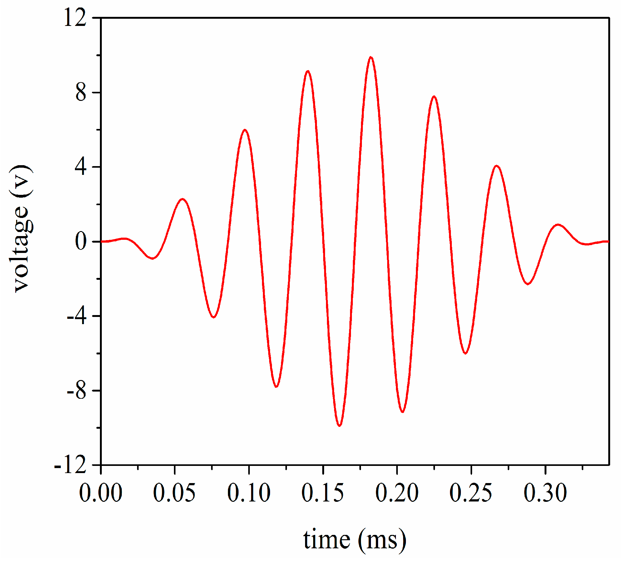
In order to investigate the vibrational velocity ratio between the front and back masses, the transient analysis is carried out using the 8 cycle single tone signal by modulated Hanning window as shown in Figure 12. At the same time, in order to obtain the large vibration speed in the front mass, the front and back masses chose heavy metals and light metals, respectively. According to the momentum conservation law, we can get
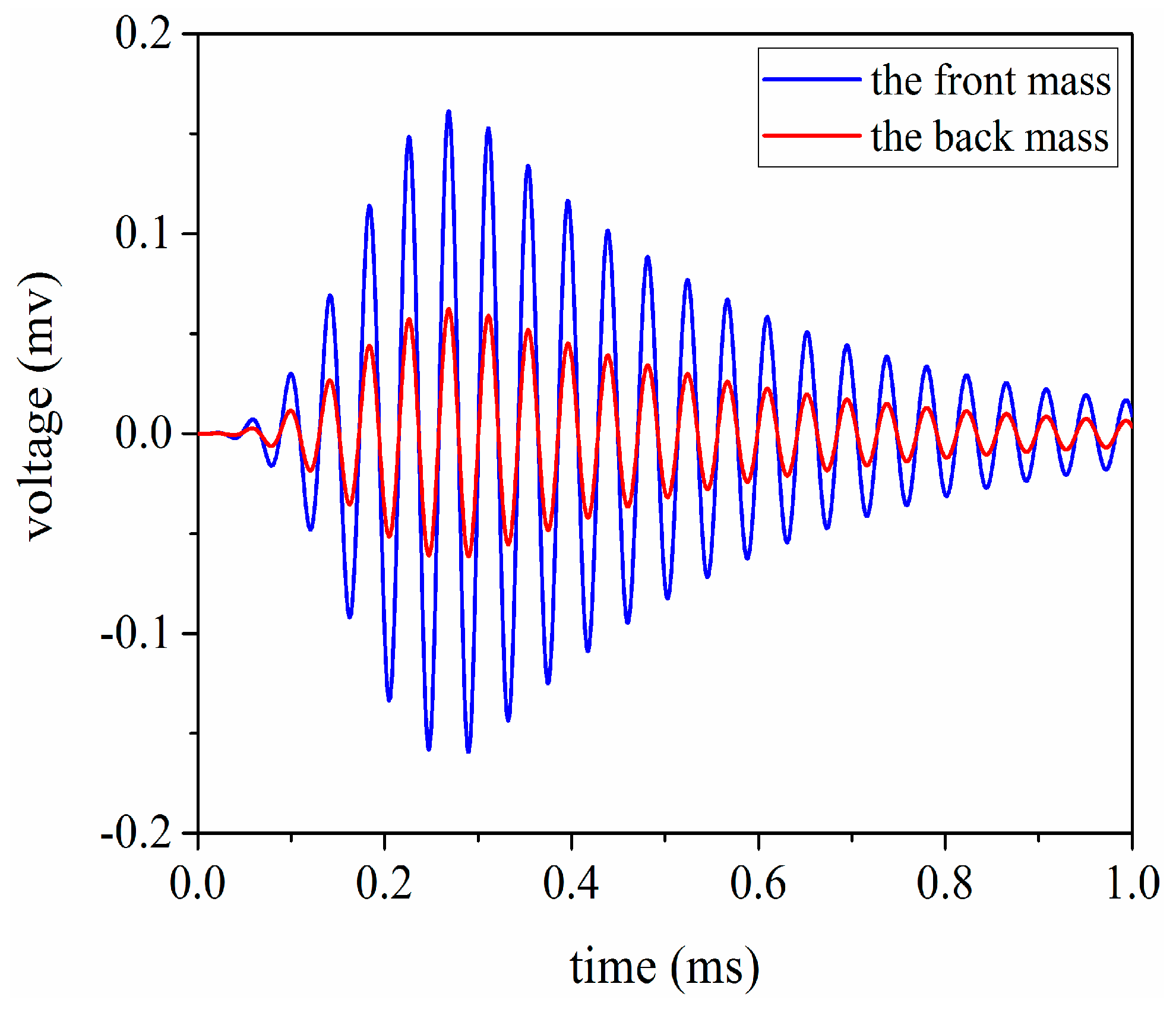
In general, if the materials of the front and back masses are chosen as aluminum and steel respectively, the vibrational velocity ratio between the front mass and the back mass is 3:1 for sandwich piezoelectric ultrasonic transducers. From Figure 13, the simulation result for the vibrational velocity ratio is obtained as
here, and represent the vibrational velocities of the front and the back masses, respectively.
4. The Pitch-Catch Setup
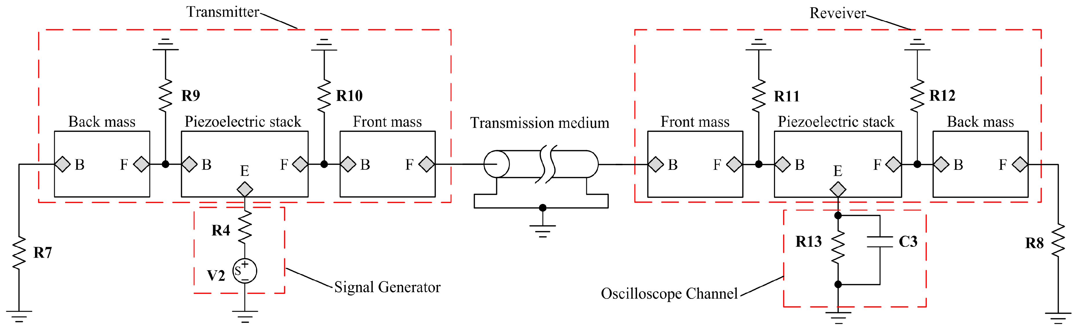
To demonstrate the application of the proposed model, a pitch-catch setup is built as shown in Figure 14. On the basis of the setup, AC and transient analysis are carried out. The simulations are compared with measurements in the time domain. It primarily includes one transmitter used to produce an ultrasonic wave signal, one receiver used to receive the ultrasonic wave signal and a piece of steel plate used as a propagation medium.
Here, the resistance has the value , the resistance has the value and the capacitance has the value . They are used to model the input impedance and capacitance of the recording channel of an oscilloscope. Also these resistances , and , are used to represent bonded layers and have the value . Then the resistances and are used to model air load and have the value .
In the first place, for the purpose of obtaining the resonance frequencies of the pitch-catch setup, the AC analysis is performed under the conditions of the length of the transmission medium having the value 20 mm and 100 mm. But the excitation source from Figure 14 need to be substituted by the AC voltage source which is the same as . The impedance analysis result is given as shown in Figure 15. According to Figure 15, it can be found that the first resonance frequencies are 21.098 and 24.363 in kHz, respectively.
In the next place, based on the pitch-catch setup from Figure 14, the transient analysis is carried out and the single tone signal modulated by Hanning window is chosen as excitation signal. The detailed analysis scheme is shown as follows:
- ①
- the length of the transmission medium is 20 mm and the excitation signal frequencies are 23.309 and 21.098 in kHz.
- ②
- the length of the transmission medium is 100 mm and the excitation signal frequencies are 23.309 and 24.363 in kHz.
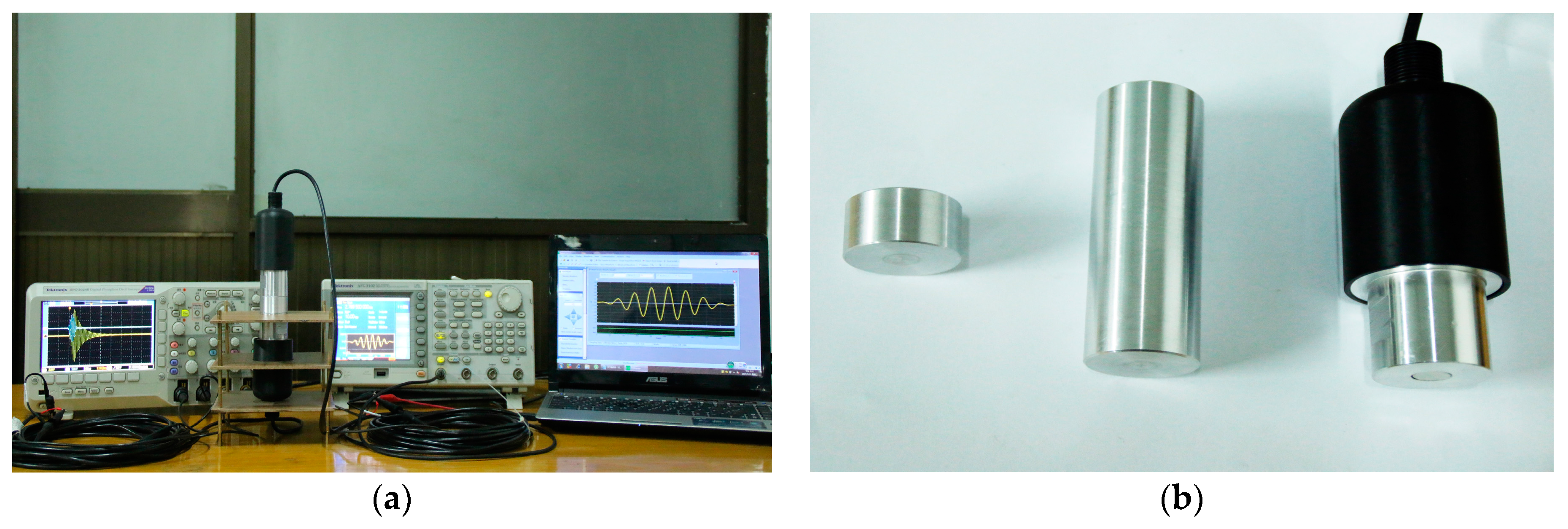
Then, to verify the accuracy of the simulated results, the pitch-catch experimental platform is built from Figure 16, which includes the arbitrary/functional generator used to generate the excitation signal, oscilloscope used to record the voltage signal and sandwich ultrasonic transducers used to transmitting and receiving the ultrasonic wave signal, the aluminum rods used to transmit the ultrasonic wave signal. For the transient analysis of the pitch-catch setup, the single tone signal modulated by Hanning window is selected as the excitation signal. Moreover, in order to make the transducer and the transmission medium fit tightly, the glycerin is used as couplant.
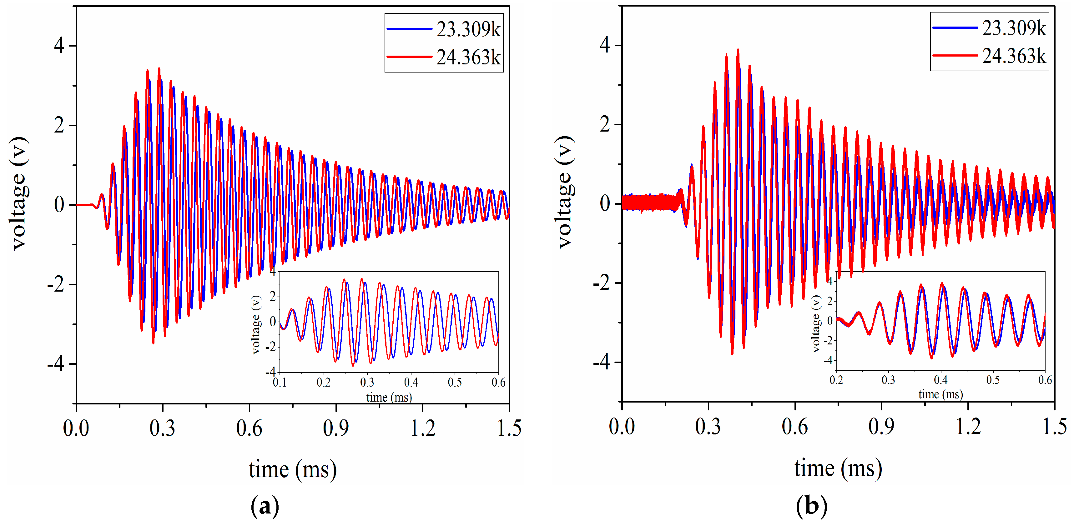
The voltage signals are received by the ultrasonic transducer under the conditions that the aluminum cylinders are 20 mm and 100 mm in length respectively. Simultaneously, these signal data are recorded by the oscilloscope. By using these recorded data, the signal waveforms received in the time domain are given as shown in Figure 17 and Figure 18. According to Figure 17 and Figure 18, it can be easily found that the simulated results have good consistency with the experimental ones. In addition, the conclusion can also be drawn that the optimal excitation frequency for the pitch-catch setup is not necessarily the resonance frequency for the sandwiched ultrasonic transducer, because the resonance frequency can be obtained under the condition of no load.
At the same time, the voltage values received are specifically listed in Table 6 and Table 7 under the length of the transmission medium having 20 mm and 100 mm respectively. From Table 6 and Table 7, and , and Vm2. represent the simulated and measured voltage values from the received ultrasonic transducer respectively and , .
There are several factors that can well explain amplitude error or difference in the received voltage in Table 6 and Table 7. Firstly, it is impossible to keep the same for each manufactured transducer. Secondly, the standard physical parameters of the transmission medium are applied in the simulation calculation, which may be different from the truthful physical parameters. Thirdly, due to the effect of frequency error and prestressed bolt for this transducer, this also can lead to relatively large amplitude error.
5. Discussion
The PSpice model of the sandwiched piezoelectric ceramic ultrasonic transducer in longitudinal vibration is proposed in this work. It is mainly for providing convenience for the design and analysis of the sandwiched ultrasonic transducers. Compared with the theory analysis method based on the Mason’s equivalent circuit of the sandwiched piezoelectric ultrasonic transducers, the proposed PSpice model has the following advantages. First, it is very easy to access the parameters such as the input electrical impedance and reactance, the vibrational velocity, the resonance and anti-resonance frequencies. Second, the proposed transducer model has great flexibility and strong expansion. Moreover, it can easily combine with the excitation, filter and amplifier circuits, which provides help to improve and optimize these circuits. Third, on the basis of the model proposed, the wireless power or data transmission system based on the sandwiched ultrasonic transducer in longitudinal or thickness vibration can be easily built; the parameters for the system are easily obtained by the AC and transient analysis, and so on.
The effect of the losses including mechanical and dielectric on the transducer performance parameters such as resonance frequency, electrical quality factor and electro-acoustical efficiency, needs be considered in practical transducers. However, these mechanical losses, such as the metal front and back masses, and the metal electrodes, are ignored in the proposed PSpice model. Therefore, for the purpose of improving the sandwiched piezoelectric ceramic transducer in longitudinal or thickness vibration, the effect of the losses for the transducer performance should be analyzed by using the lossy transmission line. Moreover, the effect of the sealed epoxy resin layer is not considered in the transducer PSpice model. For the formulation of the sealed epoxy resin layer, it can be regarded as the lossy transmission line. It is strongly suggested that the effect of the prestressed bolt can be analyzed using the finite element method. These issues are expected to be further investigated in our subsequent work.
6. Conclusions
In this paper, based on Leach’s equivalent circuit and lossless transmission line, a PSpice model of the sandwiched piezoelectric ultrasonic transducer in longitudinal vibration is proposed, and the resonance and antiresonance frequencies are obtained. To further verify the accuracy and application of the proposed model, a pitch-catch setup and an experimental platform are built; the resonance frequency is obtained and the simulated results are compared with the measured ones. In summary, based on the analysis mentioned above, some conclusions can be drawn as follows:
- (1)
- The comparisons of the measured results and simulated values of the sandwiched piezoelectric ultrasonic transducer indicate the accuracy of the proposed lossy model.
- (2)
- The PSpice model has been successfully applied to the pitch-catch setup. It is shown that the experimental results and the simulated values have good consistency. Simultaneously, we can find that the optimal excitation frequency of the sandwiched ultrasonic transducer is not necessarily the resonance frequency for the pitch-catch setup.
- (3)
- The accomplishment in PSpice can provide convenient analysis for the sandwiched piezoelectric transducers in time and frequency domains. Compared with the sandwiched piezoelectric transducer model based on Mason’s equivalent circuit, the proposed model may be more easily used to investigate the sandwiched transducers.
- (4)
- The proposed PSpice model of sandwich piezoelectric transducers can be more conveniently used to combine with other circuits such as driving circuits, filters, amplifiers, and so on.
Acknowledgments
The authors gratefully acknowledge the financial support from Natural Science Foundation of China (Grant No. 51477138), Key Research and Development Program of Shaanxi Province (Grant No. 2017ZDXM-GY-130), Xi’an City Science and Technology Project (Grant No. 2017080CG/RC043 (XALG009)).
Author Contributions
Xiaoyuan Wei and Yuan Yang performed the theoretical analysis, conceived and designed the experiments; Xiaoyuan Wei, Wenqing Yao and Lei Zhang performed the experiments and analyzed the data; Xiaoyuan Wei wrote the paper.
Conflicts of Interest
The authors declare no conflict of interest.
References
- Lin, S.Y. Study on the Langevin piezoelectric ceramic ultrasonic transducer of longitudinal-flexural composite vibration mode. Ultrasonics 2006, 44, 109–114. [Google Scholar] [CrossRef] [PubMed]
- Li, X.N.; Yao, Z.Y. Analytical modeling and experimental validation of a V-shape piezoelectric ultrasonic transducer. Smart Mater. Struct. 2016, 25, 075026. [Google Scholar] [CrossRef]
- Lin, S.Y. Analysis of the sandwich piezoelectric ultrasonic transducer in coupled vibration. J. Acoust. Soc. Am. 2005, 117, 653–661. [Google Scholar]
- Mason, W.P. Electromechanical Transducers and Wave Filters, 2nd ed.; Van Nostrand: Princeton, NJ, USA, 1948; ISBN 9780442051648. [Google Scholar]
- Redwood, M. Transient performance of a piezoelectric transducer. J. Acoust. Soc. Am. 1961, 33, 527–536. [Google Scholar] [CrossRef]
- Krimholtz, R.; Leedom, D.A.; Matthaei, G.L. New equivalent circuits for elementary piezoelectric transducers. Electron. Lett. 1970, 6, 398–399. [Google Scholar] [CrossRef]
- Morris, S.A.; Hutchens, C.G. Implementation of Mason’s model on circuit analysis programs. IEEE Trans. Ultrason. Ferroelectr. Freq. Control 1986, 33, 295–298. [Google Scholar] [CrossRef] [PubMed]
- Johansson, J.; Delsing, J. Effects of parasitic electrical components on an ultrasound system: Measurements and simulations using SPICE models. Proc. SPIE 2003, 4946, 174–182. [Google Scholar]
- Leach, W.M. Controlled-source analogous circuits and SPICE models for piezoelectric transducers. IEEE Trans. Ultrason. Ferroelectr. Freq. Control 1994, 41, 60–66. [Google Scholar] [CrossRef]
- Puttmer, A.; Hauptmann, P.; Lucklum, R. Spice model for lossy piezoceramic transducers. IEEE Trans. Ultrason. Ferroelectr. Freq. Control 1997, 44, 60–66. [Google Scholar] [CrossRef] [PubMed]
- Van, D.J.; Lofqvist, T.; Delsing, J. PSpice simulation of ultrasonic systems. IEEE Trans. Ultrason. Ferroelectr. Freq. Control 2000, 47, 1014–1024. [Google Scholar] [CrossRef]
- Guisado, A.; Torres, J.L.; González, A.M. Study of Equivalent Circuits of Piezoceramics to Use in Simulations with Pspice. Ferroelectrics 2003, 293, 307–319. [Google Scholar] [CrossRef]
- Lin, S.Y. Study on the radial composite piezoelectric ceramic transducer in radial vibration. Ultrasonics 2007, 46, 51–59. [Google Scholar] [CrossRef] [PubMed]
- Lin, S.Y.; Tian, H. Study on the sandwich piezoelectric ceramic ultrasonic transducer in thickness vibration. Smart Mater. Struct. 2008, 17, 015034. [Google Scholar] [CrossRef]
- Lin, S.Y.; Cao, H.; Qiao, X. Wireless power transmission based on sandwiched composite piezoelectric transducers in length extensional vibration. IEEE Trans. Power Electron. 2016, 31, 6134–6143. [Google Scholar] [CrossRef]
- Cheng, D.K. Field and Wave Electromagnetics, 2nd ed.; Tsinghua University Press: Beijing, China, 2007; pp. 438–439. ISBN 9787302152125. [Google Scholar]
- Kinsler, L.E.; Frey, A.R.; Coppens, A.B.; Sanders, J.V. Fundamentals of Acoustics, 4th ed.; Wiley: New York, NY, USA, 1999; pp. 119–120. ISBN 0471847895. [Google Scholar]
- Gandole, Y.B. Computer modeling and simulation of ultrasonic signal processing and measurements. Phys. Res. Int. 2012, 3, 829–834. [Google Scholar] [CrossRef]
- Dennis, F. Analog Design and Simulation Using OrCAD Capture and PSpice, 1st ed.; Newnes: Oxford, UK, 2011; pp. 217–218. ISBN 9780080970950. [Google Scholar]
- Galloy, L.; Berquez, L.; Baudoin, F. PSpice modeling of the pulsed electro-acoustic signal. IEEE Trans. Dielectr. Electri. Insul. 2014, 21, 1143–1153. [Google Scholar] [CrossRef]
- Chen, Y.C.; Wu, L.; Chang, K.K. Analysis and simulation of stacked-segment electromechanical transducers with partial electrical excitation by PSPICE. Jpn. J. Appl. Phys. 1997, 36, 6550–6557. [Google Scholar] [CrossRef]
- Antlinger, H.; Beigelbeck, R.; Clara, S. Investigation and modeling of an acoustoelectric sensor setup for the determination of the longitudinal viscosity. IEEE Trans. Ultrason. Ferroelectr. Freq. Control 2016, 63, 2187–2197. [Google Scholar] [CrossRef] [PubMed]
- Nakamura, K. Ultrasonic Transducers Materials and Design for Sensors, Actuators and Medical Application, 1st ed.; Woodhead Publishing Limited: Sawston, UK, 2012; pp. 13–14. ISBN 9781845699895. [Google Scholar]
- Du, G.H.; Zhu, Z.M.; Gong, X.F. Fundamentals of Acoustics, 3rd ed.; Nanjing University Press: Nanjing, China, 2012; pp. 351–352. ISBN 9787305097782. [Google Scholar]
Figure 1.
Simplified structure diagram of a sandwich piezoelectric ultrasonic transducer.
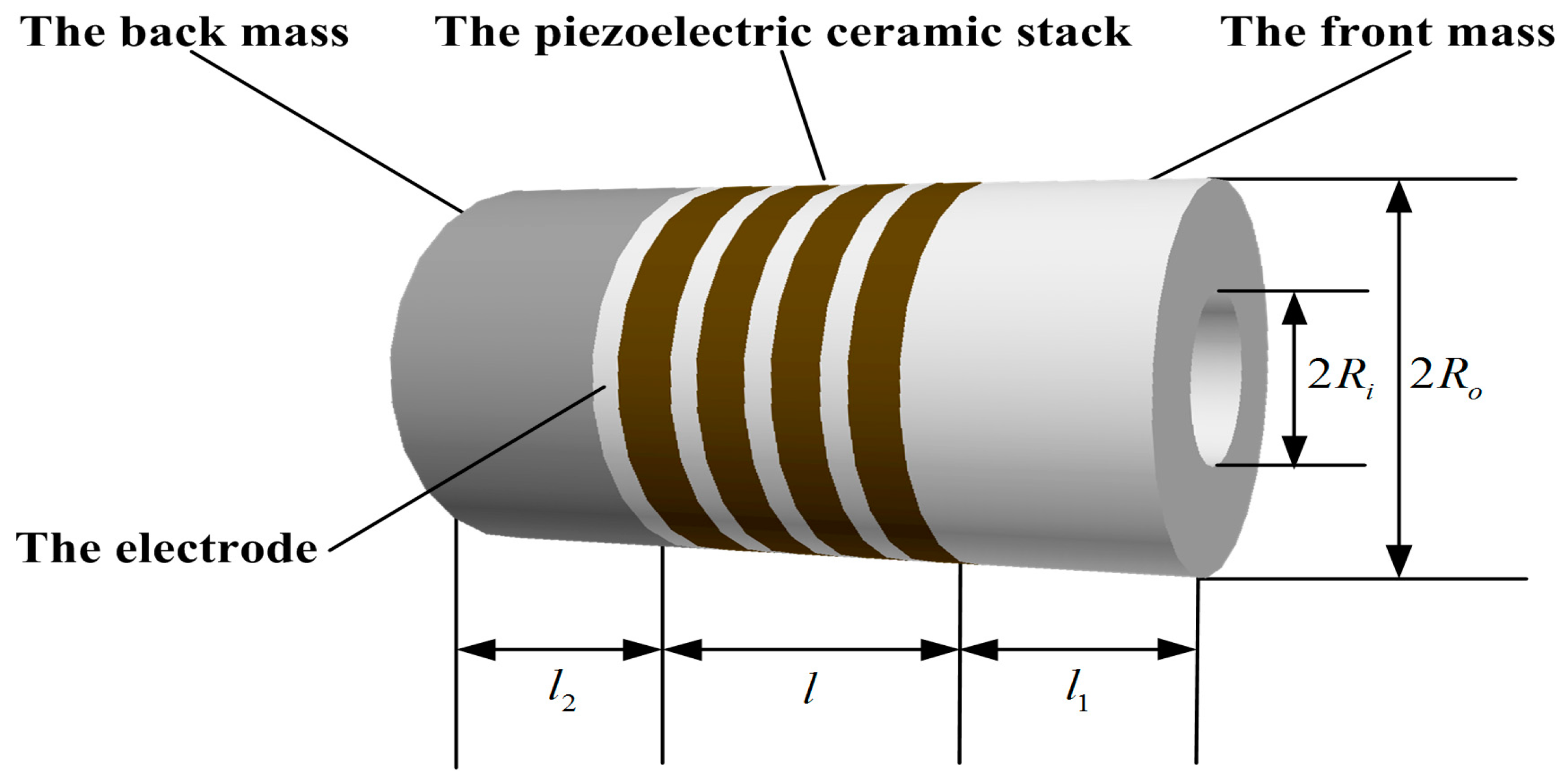
Figure 2.
The circuit structure diagram of a transmission line of a length of Δz.

Figure 3.
Piezoelectric ceramic ring vibrating in thickness mode.

Figure 4.
Leach’s equivalent circuit model for a thickness vibration piezoelectric ring.

Figure 5.
The lossless transmission line model in PSpice.
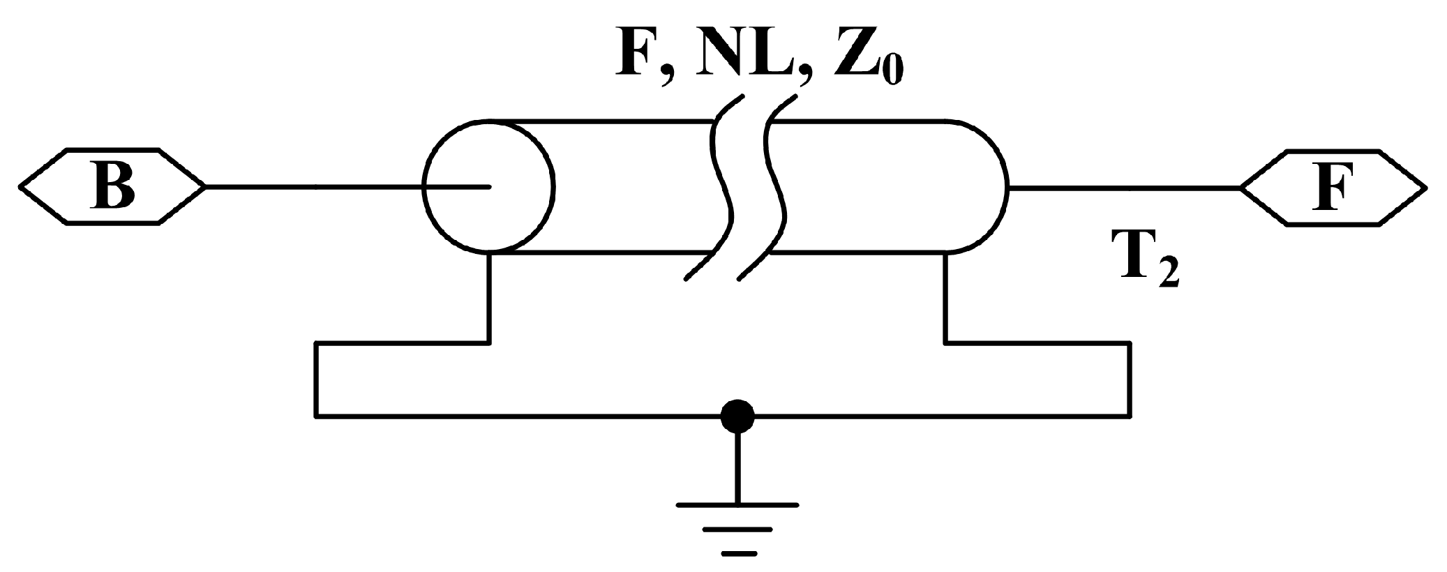
Figure 6.
PSpice circuit of the Leach’s model of a piezoelectric ceramic ring vibrating in thickness direction.
Figure 6.
PSpice circuit of the Leach’s model of a piezoelectric ceramic ring vibrating in thickness direction.
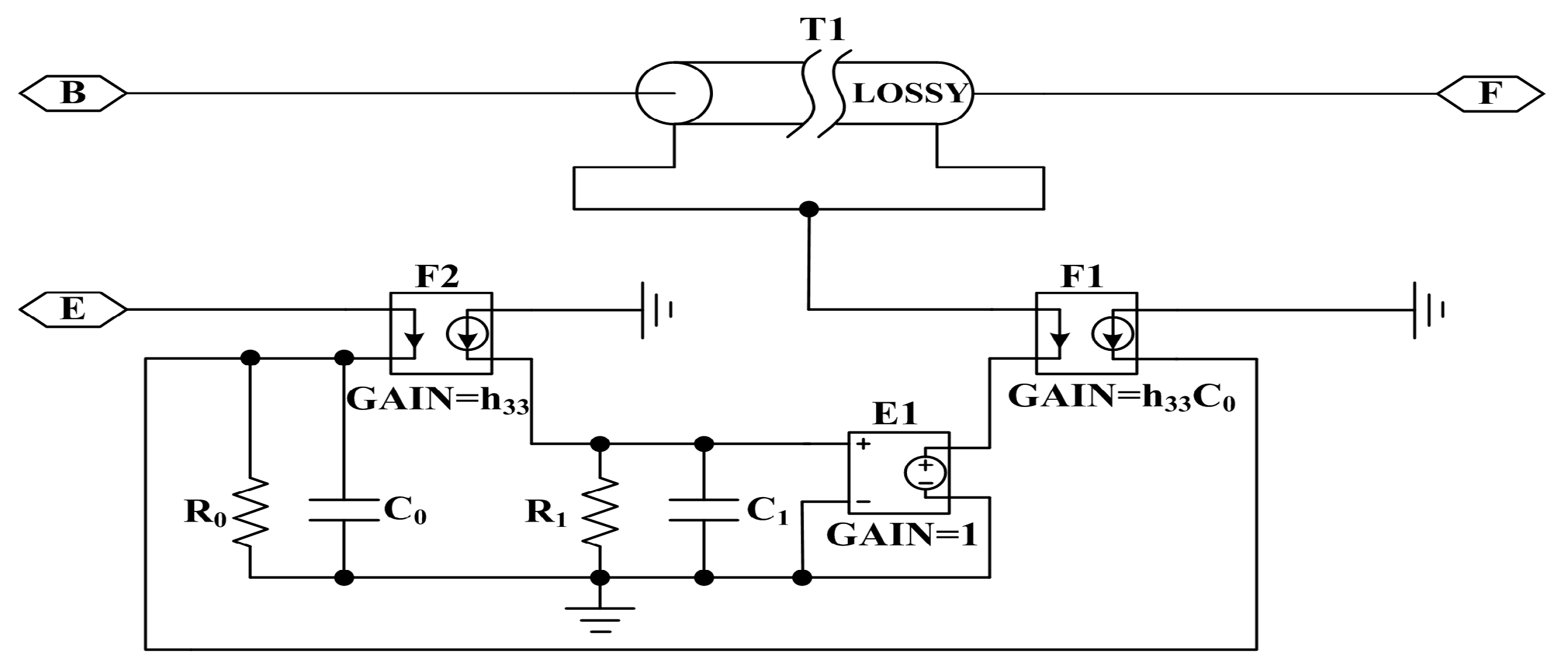
Figure 7.
The piezoelectric ceramic stack composed of four same thickness-poled rings.

Figure 8.
PSpice circuit model of a piezoelectric ceramic stack with electrodes.

Figure 9.
The AC analysis simulation circuit of the sandwiched piezoelectric ultrasonic transducer.
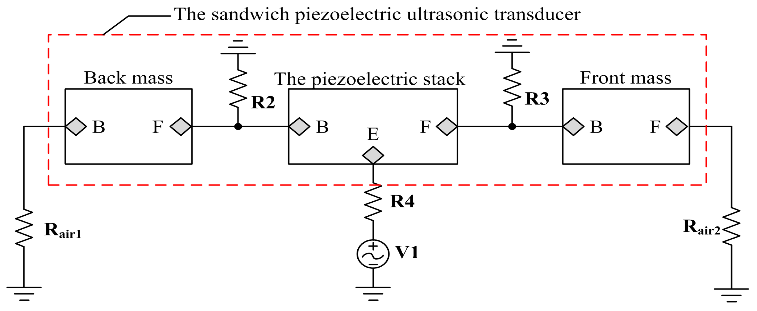
Figure 10.
The impedance test of the sandwiched ultrasonic transducer.
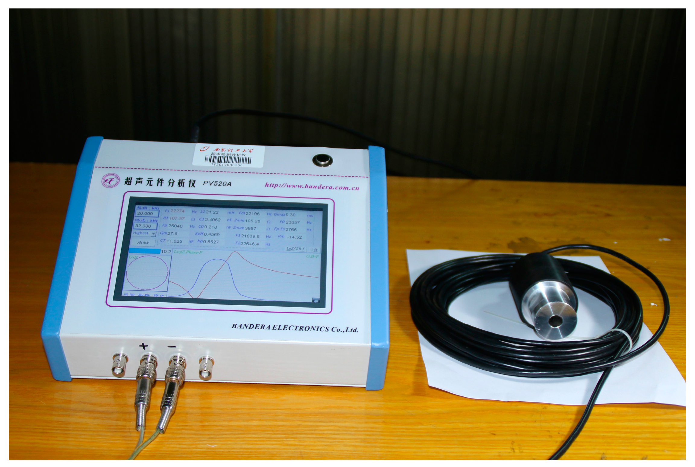
Figure 11.
The impedance-frequency relationship of the sandwiched ultrasonic transducer.
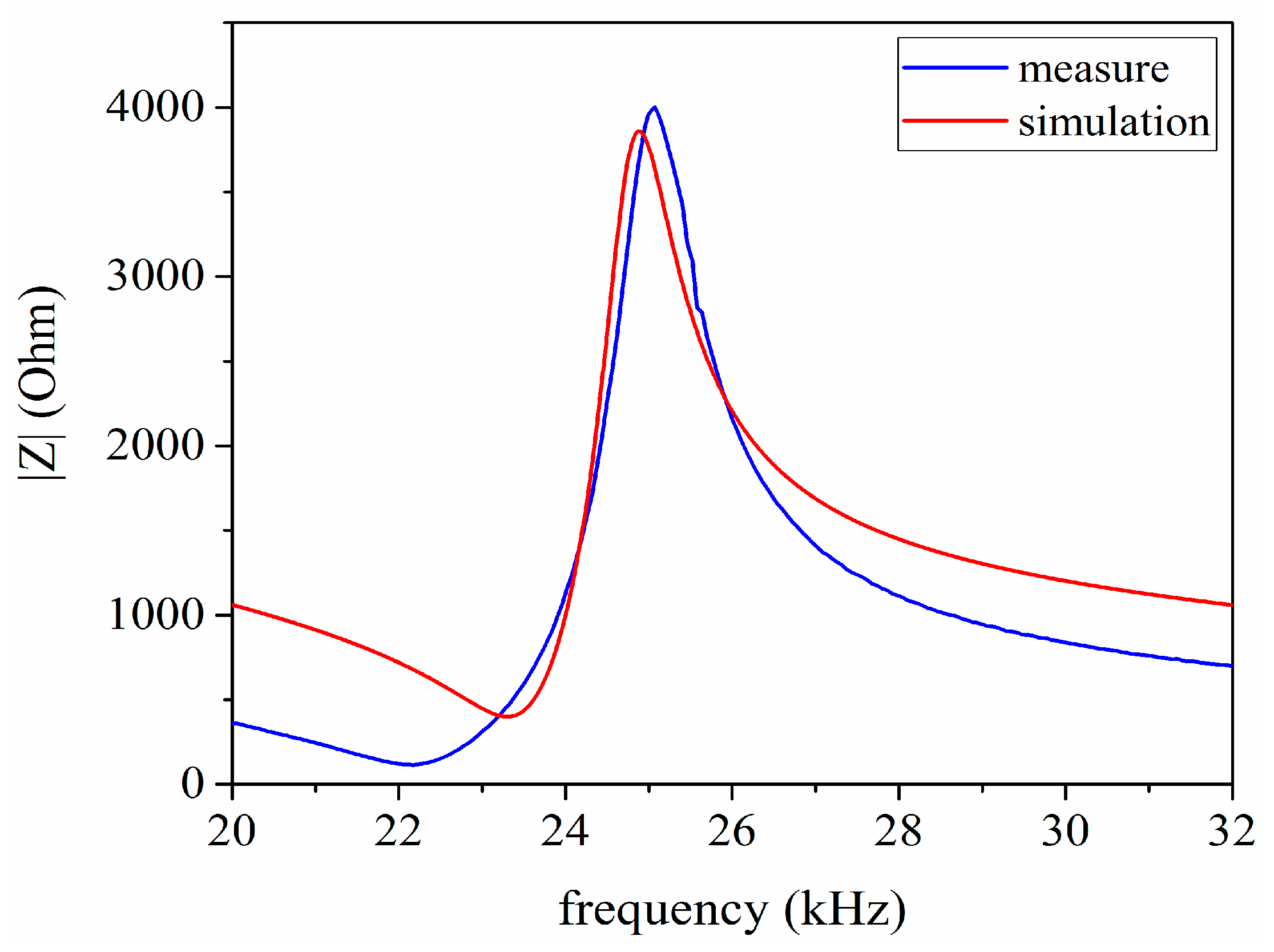
Figure 12.
The single tone signal modulated by Hanning window.

Figure 13.
The vibrational velocity ratio between the front and back masses.

Figure 14.
The simulation circuit of the pitch-catch setup.

Figure 15.
The impedance analysis of the pitch-catch setup.
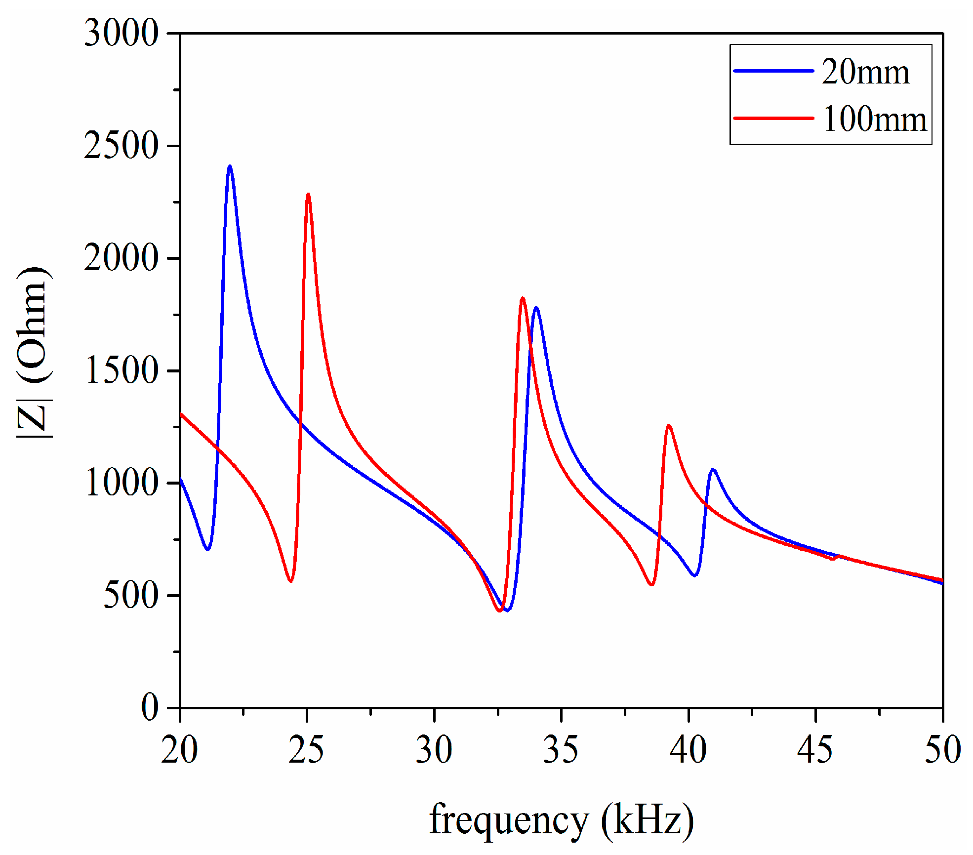
Figure 16.
The pitch-catch experimental platform, (a) experimental testing; (b) Aluminum cylinders and sandwiched piezoelectric ultrasonic transducers.
Figure 16.
The pitch-catch experimental platform, (a) experimental testing; (b) Aluminum cylinders and sandwiched piezoelectric ultrasonic transducers.

Figure 17.
The signal waveform received by the ultrasonic transducer under the condition that the aluminum cylinder is 20 mm in length, (a) the simulated results; (b) experimental results.
Figure 17.
The signal waveform received by the ultrasonic transducer under the condition that the aluminum cylinder is 20 mm in length, (a) the simulated results; (b) experimental results.
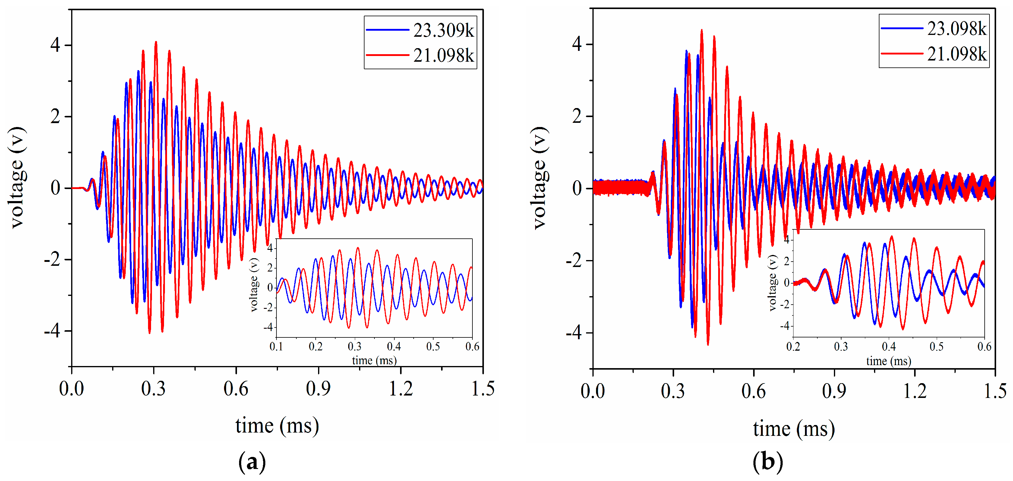
Figure 18.
The signal waveform received by the ultrasonic transducer under the condition that the aluminum cylinder is 100 mm in length, (a) the simulated results; (b) experimental results.
Figure 18.
The signal waveform received by the ultrasonic transducer under the condition that the aluminum cylinder is 100 mm in length, (a) the simulated results; (b) experimental results.


Table 1.
The material parameters of the piezoelectric ceramic PZT-4.
| Parameters | Value |
|---|---|
| (kg/m3) | 7500 |
| (m/s) | 4600 |
| A (m2) | 957.4 × 10⁻⁶ |
| (m) | 5 × 10⁻³ |
| 500 | |
| 0.004 | |
| (m/F) | 1.78 × 10⁸ |
| (V/m) | 27.12 × 10⁸ |
Table 2.
The material parameters of the aluminum used in the front mass.
| Parameters | Value |
|---|---|
| (kg/m3) | 2700 |
| (m/s) | 5037 |
| (m2) | 1075.2 × 10−6 |
| (m) | 43 × 10−3 |
Table 3.
The material parameters of the steel used in the back mass.
| Parameters | Value |
|---|---|
| (kg/m3) | 7800 |
| (m/s) | 5262 |
| (m2) | 1134.1 × 10−6 |
| (m) | 45 × 10−3 |
Table 4.
The material parameters of the copper used in the metal electrodes.
| Parameters | Value |
|---|---|
| (kg/m3) | 8900 |
| (m/s) | 3718 |
| (m2) | 1134.1 × 10−6 |
| (m) | 0.5 × 10⁻³ |
Table 5.
The measured and simulated resonance and anti-resonance frequencies for a sandwich piezoelectric ultrasonic transducer.
Table 5.
The measured and simulated resonance and anti-resonance frequencies for a sandwich piezoelectric ultrasonic transducer.
| Parameters | |||
|---|---|---|---|
| 23.309 | 22.2 | 4.99% | |
| 24.885 | 25.1 | 0.86% |
Table 6.
The measured and simulated voltage values under the condition of the length for the transmission medium having 20 mm.
Table 6.
The measured and simulated voltage values under the condition of the length for the transmission medium having 20 mm.
| Frequency (kHz) | VS1(V) | Vm1(V) | Δ1% |
|---|---|---|---|
| 23.309 | 6.65 | 7.76 | 14.3% |
| 21.098 | 8.16 | 8.88 | 8.1% |
Table 7.
The measured and simulated voltage values under the condition of the length for the transmission medium having 100 mm.
Table 7.
The measured and simulated voltage values under the condition of the length for the transmission medium having 100 mm.
| Frequency (kHz) | VS2(V) | Vm2(V) | Δ2% |
|---|---|---|---|
| 23.309 | 6.32 | 6.96 | 9.2% |
| 24.363 | 6.92 | 7.76 | 10.8% |
© 2017 by the authors. Licensee MDPI, Basel, Switzerland. This article is an open access article distributed under the terms and conditions of the Creative Commons Attribution (CC BY) license (http://creativecommons.org/licenses/by/4.0/).
Share and Cite
MDPI and ACS Style
Wei, X.; Yang, Y.; Yao, W.; Zhang, L. PSpice Modeling of a Sandwich Piezoelectric Ceramic Ultrasonic Transducer in Longitudinal Vibration. Sensors 2017, 17, 2253. https://doi.org/10.3390/s17102253
AMA Style
Wei X, Yang Y, Yao W, Zhang L. PSpice Modeling of a Sandwich Piezoelectric Ceramic Ultrasonic Transducer in Longitudinal Vibration. Sensors. 2017; 17(10):2253. https://doi.org/10.3390/s17102253
Chicago/Turabian StyleWei, Xiaoyuan, Yuan Yang, Wenqing Yao, and Lei Zhang. 2017. "PSpice Modeling of a Sandwich Piezoelectric Ceramic Ultrasonic Transducer in Longitudinal Vibration" Sensors 17, no. 10: 2253. https://doi.org/10.3390/s17102253
Note that from the first issue of 2016, this journal uses article numbers instead of page numbers. See further details here.