
Optical Fibre Sensors Using Graphene-Based Materials: A Review

 ,
,  ,
,  and
and
Abstract
:1. Introduction
2. Graphene Materials
2.1. Graphene Discovery
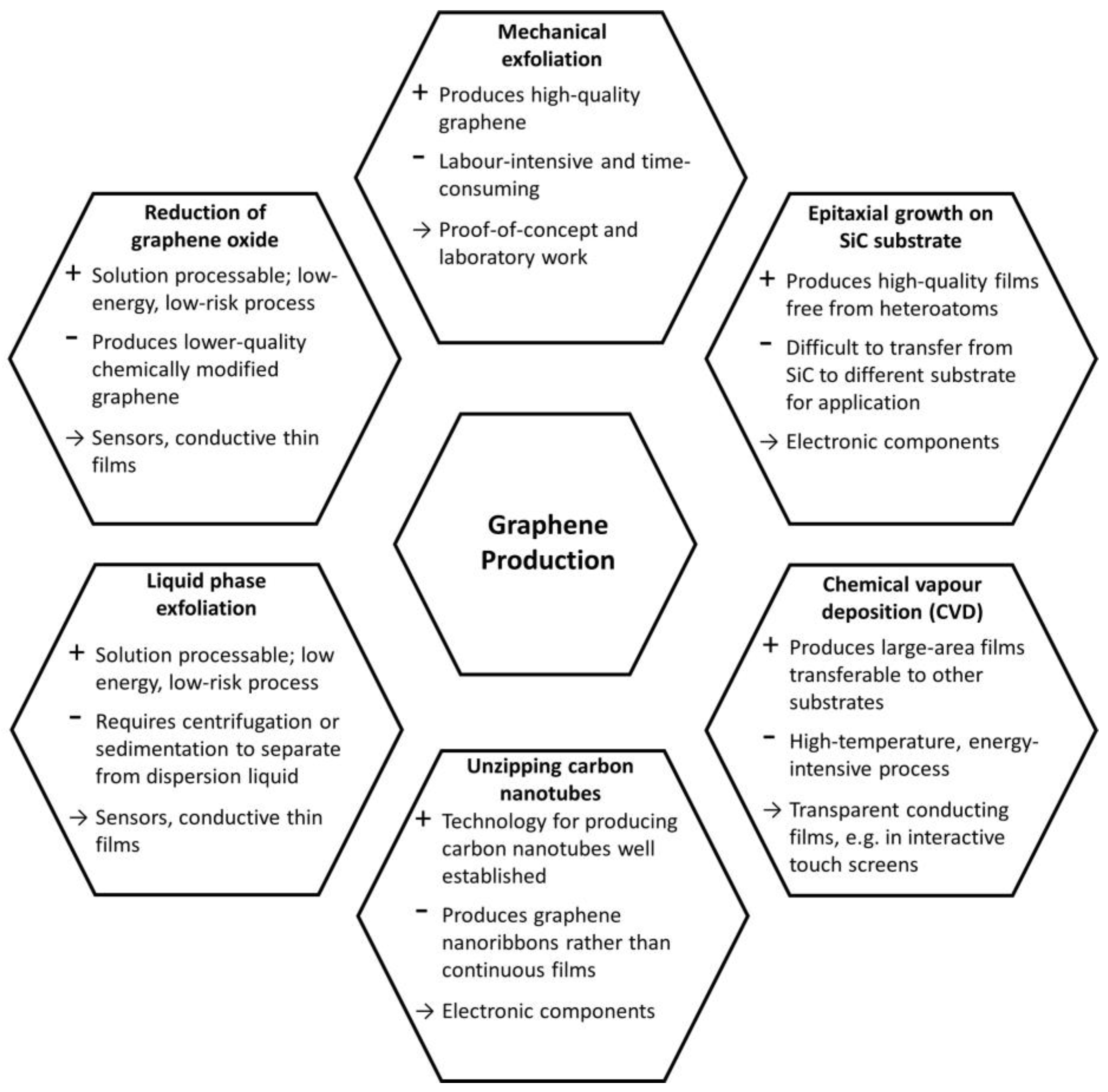
2.2. Synthesis Methods of Graphene
2.2.1. Micromechanical Exfoliation
2.2.2. Epitaxial Growth on SiC Substrates
2.2.3. Chemical Vapour Deposition
2.2.4. Unzipping of Carbon Nanotubes
2.2.5. Liquid Phase Exfoliation of Graphite
2.2.6. Reduction of Exfoliated Graphene Oxide
3. Optical Fibre Sensors Using Graphene-Based Materials
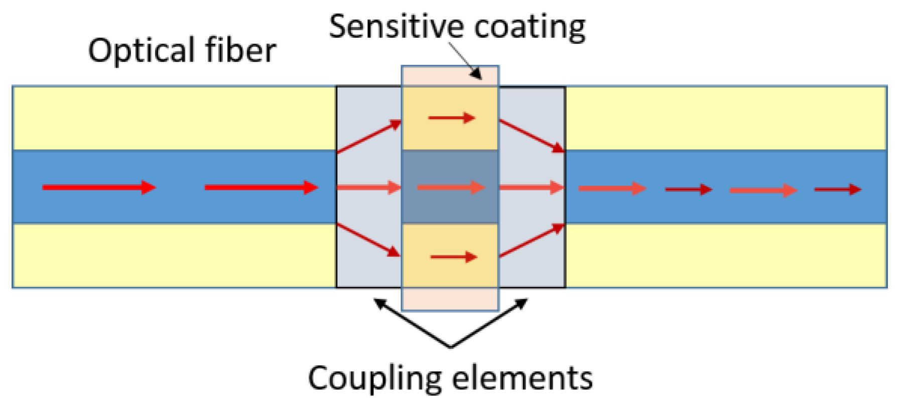
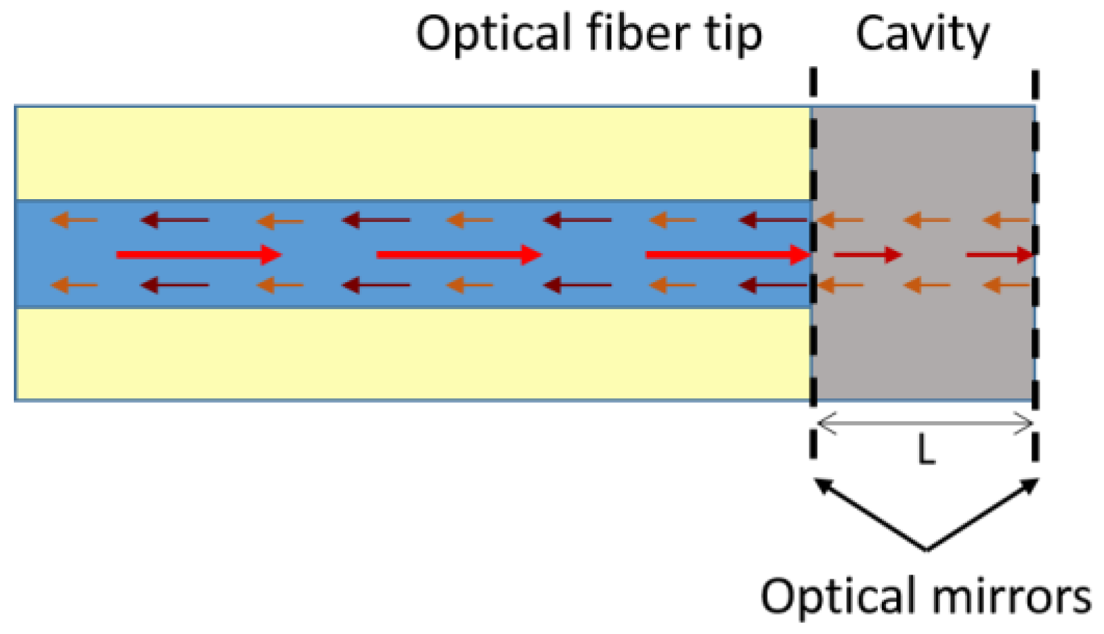
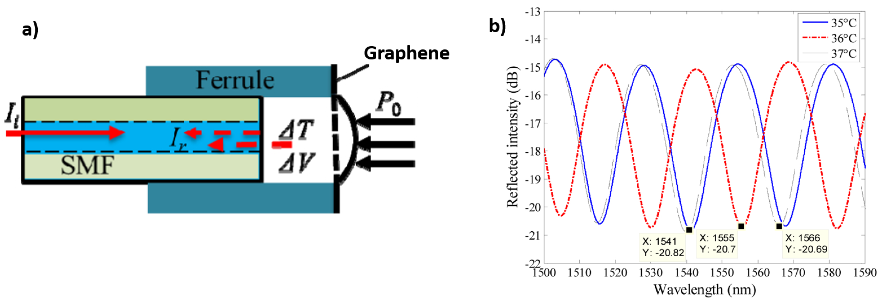
3.1. Interferometry Based Optical Fibre Sensors Using Graphene-Based Coatings
3.2. Surface Plasmon Resonance Optical Fibre Sensors Using Graphene-Based Coatings
3.3. Fibre Bragg Gratings Sensors Using Graphene-Based Coatings
3.4. Absorption-Based Optical Fibre Sensors Using Graphene-Based Coatings
3.5. Fluorescence-Based Optical Fibre Sensors Using Graphene-Based Coatings
4. Conclusions and Future Trends
Acknowledgments
Conflicts of Interest
References
- Novoselov, K.S.; Geim, A.K.; Morozov, S.V.; Jiang, D.; Zhang, Y.; Dubonos, S.V.; Grigorieva, I.V.; Firsov, A.A. Electric field effect in atomically thin carbon films. Science 2004, 306, 666–669. [Google Scholar] [CrossRef] [PubMed]
- Varghese, S.S.; Lonkar, S.; Singh, K.K.; Swaminathan, S.; Abdala, A. Recent advances in graphene based gas sensors. Sens. Actuators B Chem. 2015, 218, 160–183. [Google Scholar] [CrossRef]
- Bonfig, K.W.; Denker, M.; Kuipers, U. Das direkte digitale messverfahren als grundlage einfacher und dennoch genauer und storsicherer sensoren. Sensor 1988, 3, 103–108. [Google Scholar]
- Matko, V. Next generation at-cut quartz crystal sensing devices. Sensors 2011, 11, 4474–4482. [Google Scholar] [CrossRef] [PubMed]
- Matko, V.; Jezernik, K. New quartz oscillator switching method for nano-henry range inductance measurements. Sensors 2012, 12, 3105–3117. [Google Scholar] [CrossRef] [PubMed]
- Matko, V.; Milanović, M. Temperature-compensated capacitance-frequency converter with high resolution. Sens. Actuators A Phys. 2014, 220, 262–269. [Google Scholar] [CrossRef]
- Culshaw, B. Optical fiber sensor technologies: Opportunities and-perhaps-pitfalls. J. Lightwave Technol. 2004, 22, 39–50. [Google Scholar] [CrossRef]
- Elosua, C.; Matias, I.R.; Bariain, C.; Arregui, F.J. Volatile organic compound optical fiber sensors: A review. Sensors 2006, 6, 1440–1465. [Google Scholar] [CrossRef]
- Lee, B. Review of the present status of optical fiber sensors. Opt. Fiber Technol. 2003, 9, 57–79. [Google Scholar] [CrossRef]
- Culshaw, B.; Kersey, A. Fiber-optic sensing: A historical perspective. J. Lightwave Technol. 2008, 26, 1064–1078. [Google Scholar] [CrossRef]
- Lee, B.; Roh, S.; Park, J. Current status of micro- and nano-structured optical fiber sensors. Opt. Fiber Technol. 2009, 15, 209–221. [Google Scholar] [CrossRef]
- Wolfbeis, O.S. Fiber-optic chemical sensors and biosensors. Anal. Chem. 2008, 80, 4269–4283. [Google Scholar] [CrossRef] [PubMed]
- Roriz, P.; Carvalho, L.; Frazão, O.; Santos, J.L.; Simões, J.A. From conventional sensors to fibre optic sensors for strain and force measurements in biomechanics applications: A review. J. Biomech. 2014, 47, 1251–1261. [Google Scholar] [CrossRef] [PubMed]
- Wang, X.D.; Wolfbeis, O.S. Fiber-optic chemical sensors and biosensors (2008–2012). Anal. Chem. 2013, 85, 487–508. [Google Scholar] [CrossRef] [PubMed]
- Castro Neto, A.H.; Guinea, F.; Peres, N.M.R.; Novoselov, K.S.; Geim, A.K. The electronic properties of graphene. Rev. Mod. Phys. 2009, 81, 109–162. [Google Scholar] [CrossRef]
- Geim, A.K.; Novoselov, K.S. The rise of graphene. Nat. Mater. 2007, 6, 183–191. [Google Scholar] [CrossRef] [PubMed]
- Boehm, H.P.; Setton, R.; Stumpp, E. Nomenclature and terminology of graphite intercalation compounds. Carbon 1986, 24, 241–245. [Google Scholar] [CrossRef]
- Novoselov, K.S.; Jiang, D.; Schedin, F.; Booth, T.J.; Khotkevich, V.V.; Morozov, S.V.; Geim, A.K. Two-dimensional atomic crystals. Proc. Natl. Acad. Sci. USA 2005, 102, 10451–10453. [Google Scholar] [CrossRef] [PubMed]
- Siefker-Radtke, A.O.; Millikan, R.E.; Kamat, A.M.; Shen, Y.; Williams, D.L.; Grossman, H.B.; Dinney, C.P. A phase II trial of sequential neoadjuvant chemotherapy with ifosfamide, doxorubicin, and gemcitabine (IAG), followed by cisplatin, gemcitabine and ifosfamide (CGI) in locally advanced urothelial cancer (UC): Final results from the M.D. Anderson cancer center. J. Clin. Oncol. 2008, 26. [Google Scholar] [CrossRef]
- Wu, Z.S.; Ren, W.C.; Gao, L.B.; Liu, B.L.; Jiang, C.B.; Cheng, H.M. Synthesis of high-quality graphene with a pre-determined number of layers. Carbon 2009, 47, 493–499. [Google Scholar] [CrossRef]
- Stankovich, S.; Dikin, D.A.; Dommett, G.H.B.; Kohlhaas, K.M.; Zimney, E.J.; Stach, E.A.; Piner, R.D.; Nguyen, S.T.; Ruoff, R.S. Graphene-based composite materials. Nature 2006, 442, 282–286. [Google Scholar] [CrossRef] [PubMed]
- Stankovich, S.; Dikin, D.A.; Piner, R.D.; Kohlhaas, K.A.; Kleinhammes, A.; Jia, Y.; Wu, Y.; Nguyen, S.T.; Ruoff, R.S. Synthesis of graphene-based nanosheets via chemical reduction of exfoliated graphite oxide. Carbon 2007, 45, 1558–1565. [Google Scholar] [CrossRef]
- Berger, C.; Song, Z.M.; Li, T.B.; Li, X.B.; Ogbazghi, A.Y.; Feng, R.; Dai, Z.T.; Marchenkov, A.N.; Conrad, E.H.; First, P.N.; et al. Ultrathin epitaxial graphite: 2d electron gas properties and a route toward graphene-based nanoelectronics. J. Phys. Chem. B 2004, 108, 19912–19916. [Google Scholar] [CrossRef]
- Berger, C.; Song, Z.M.; Li, X.B.; Wu, X.S.; Brown, N.; Naud, C.; Mayou, D.; Li, T.B.; Hass, J.; Marchenkov, A.N.; et al. Electronic confinement and coherence in patterned epitaxial graphene. Science 2006, 312, 1191–1196. [Google Scholar] [CrossRef] [PubMed]
- Yu, Q.K.; Lian, J.; Siriponglert, S.; Li, H.; Chen, Y.P.; Pei, S.S. Graphene segregated on ni surfaces and transferred to insulators. Appl. Phys. Lett. 2008, 93. [Google Scholar] [CrossRef]
- Zhang, Y.; Zhang, L.Y.; Zhou, C.W. Review of chemical vapor deposition of graphene and related applications. Acc. Chem. Res. 2013, 46, 2329–2339. [Google Scholar] [CrossRef] [PubMed]
- Kosynkin, D.V.; Higginbotham, A.L.; Sinitskii, A.; Lomeda, J.R.; Dimiev, A.; Price, B.K.; Tour, J.M. Longitudinal unzipping of carbon nanotubes to form graphene nanoribbons. Nature 2009, 458, 872–876. [Google Scholar] [CrossRef] [PubMed]
- Genorio, B.; Lu, W.; Dimiev, A.M.; Zhu, Y.; Raji, A.R.O.; Novosel, B.; Alemany, L.B.; Tour, J.M. In situ intercalation replacement and selective functionalization of graphene nanoribbon stacks. ACS Nano 2012, 6, 4231–4240. [Google Scholar] [CrossRef] [PubMed]
- Du, W.C.; Jiang, X.Q.; Zhu, L.H. From graphite to graphene: Direct liquid-phase exfoliation of graphite to produce single- and few-layered pristine graphene. J. Mater. Chem. A 2013, 1, 10592–10606. [Google Scholar] [CrossRef]
- Hernandez, Y.; Nicolosi, V.; Lotya, M.; Blighe, F.M.; Sun, Z.Y.; De, S.; McGovern, I.T.; Holland, B.; Byrne, M.; Gun’ko, Y.K.; et al. High-yield production of graphene by liquid-phase exfoliation of graphite. Nat. Nanotechnol. 2008, 3, 563–568. [Google Scholar] [CrossRef] [PubMed]
- Lotya, M.; Hernandez, Y.; King, P.J.; Smith, R.J.; Nicolosi, V.; Karlsson, L.S.; Blighe, F.M.; De, S.; Wang, Z.M.; McGovern, I.T.; et al. Liquid phase production of graphene by exfoliation of graphite in surfactant/water solutions. J. Am. Chem. Soc. 2009, 131, 3611–3620. [Google Scholar] [CrossRef] [PubMed]
- Gao, X.F.; Jang, J.; Nagase, S. Hydrazine and thermal reduction of graphene oxide: Reaction mechanisms, product structures, and reaction design. J. Phys. Chem. C 2010, 114, 832–842. [Google Scholar] [CrossRef]
- Stankovich, S.; Piner, R.D.; Chen, X.Q.; Wu, N.Q.; Nguyen, S.T.; Ruoff, R.S. Stable aqueous dispersions of graphitic nanoplatelets via the reduction of exfoliated graphite oxide in the presence of poly(sodium 4-styrenesulfonate). J. Mater. Chem. 2006, 16, 155–158. [Google Scholar] [CrossRef]
- Geim, A.K. Graphene: Status and prospects. Science 2009, 324, 1530–1534. [Google Scholar] [CrossRef] [PubMed]
- Hu, Y.K.; Ruan, M.; Guo, Z.L.; Dong, R.; Palmer, J.; Hankinson, J.; Berger, C.; de Heer, W.A. Structured epitaxial graphene: Growth and properties. J. Phys. D Appl. Phys. 2012, 45. [Google Scholar] [CrossRef]
- De Heer, W.A.; Berger, C.; Ruan, M.; Sprinkle, M.; Li, X.B.; Hu, Y.K.; Zhang, B.Q.; Hankinson, J.; Conrad, E. Large area and structured epitaxial graphene produced by confinement controlled sublimation of silicon carbide. Proc. Natl. Acad. Sci. USA 2011, 108, 16900–16905. [Google Scholar] [CrossRef] [PubMed]
- Li, X.S.; Cai, W.W.; An, J.H.; Kim, S.; Nah, J.; Yang, D.X.; Piner, R.; Velamakanni, A.; Jung, I.; Tutuc, E.; et al. Large-area synthesis of high-quality and uniform graphene films on copper foils. Science 2009, 324, 1312–1314. [Google Scholar] [CrossRef] [PubMed]
- Reina, A.; Jia, X.T.; Ho, J.; Nezich, D.; Son, H.B.; Bulovic, V.; Dresselhaus, M.S.; Kong, J. Large area, few-layer graphene films on arbitrary substrates by chemical vapor deposition. Nano Lett. 2009, 9, 30–35. [Google Scholar] [CrossRef] [PubMed]
- Campos-Delgado, J.; Romo-Herrera, J.M.; Jia, X.T.; Cullen, D.A.; Muramatsu, H.; Kim, Y.A.; Hayashi, T.; Ren, Z.F.; Smith, D.J.; Okuno, Y.; et al. Bulk production of a new form of sp(2) carbon: Crystalline graphene nanoribbons. Nano Lett. 2008, 8, 2773–2778. [Google Scholar] [CrossRef] [PubMed]
- Bae, S.; Kim, H.; Lee, Y.; Xu, X.F.; Park, J.S.; Zheng, Y.; Balakrishnan, J.; Lei, T.; Kim, H.R.; Song, Y.I.; et al. Roll-to-roll production of 30-inch graphene films for transparent electrodes. Nat. Nanotechnol. 2010, 5, 574–578. [Google Scholar] [CrossRef] [PubMed]
- Lin, M.Y.; Guo, W.C.; Wu, M.H.; Wang, P.Y.; Liu, T.H.; Pao, C.W.; Chang, C.C.; Lee, S.C.; Lin, S.Y. Low-temperature grown graphene films by using molecular beam epitaxy. Appl. Phys. Lett. 2012, 101. [Google Scholar] [CrossRef]
- Iijima, S. Helical microtubules of graphitic carbon. Nature 1991, 354, 56–58. [Google Scholar] [CrossRef]
- Jiao, L.Y.; Zhang, L.; Wang, X.R.; Diankov, G.; Dai, H.J. Narrow graphene nanoribbons from carbon nanotubes. Nature 2009, 458, 877–880. [Google Scholar] [CrossRef] [PubMed]
- Jiao, L.Y.; Wang, X.R.; Diankov, G.; Wang, H.L.; Dai, H.J. Facile synthesis of high-quality graphene nanoribbons. Nat. Nanotechnol. 2010, 5, 321–325. [Google Scholar] [CrossRef] [PubMed]
- Torrisi, F.; Hasan, T.; Wu, W.P.; Sun, Z.P.; Lombardo, A.; Kulmala, T.S.; Hsieh, G.W.; Jung, S.J.; Bonaccorso, F.; Paul, P.J.; et al. Inkjet-printed graphene electronics. ACS Nano 2012, 6, 2992–3006. [Google Scholar] [CrossRef] [PubMed]
- Hummers, W.S.; Offeman, R.E. Preparation of graphitic oxide. J. Am. Chem. Soc. 1958, 80, 1339. [Google Scholar] [CrossRef]
- Lerf, A.; He, H.Y.; Forster, M.; Klinowski, J. Structure of graphite oxide revisited. J. Phys. Chem. B 1998, 102, 4477–4482. [Google Scholar] [CrossRef]
- He, H.Y.; Klinowski, J.; Forster, M.; Lerf, A. A new structural model for graphite oxide. Chem. Phys. Lett. 1998, 287, 53–56. [Google Scholar] [CrossRef]
- Pei, S.F.; Cheng, H.M. The reduction of graphene oxide. Carbon 2012, 50, 3210–3228. [Google Scholar] [CrossRef]
- Kopelevich, Y.; Esquinazi, P. Graphene physics in graphite. Adv. Mater. 2007, 19, 4559–4563. [Google Scholar] [CrossRef]
- Schniepp, H.C.; Li, J.L.; McAllister, M.J.; Sai, H.; Herrera-Alonso, M.; Adamson, D.H.; Prud’homme, R.K.; Car, R.; Saville, D.A.; Aksay, I.A. Functionalized single graphene sheets derived from splitting graphite oxide. J. Phys. Chem. B 2006, 110, 8535–8539. [Google Scholar] [CrossRef] [PubMed]
- Cote, L.J.; Cruz-Silva, R.; Huang, J.X. Flash reduction and patterning of graphite oxide and its polymer composite. J. Am. Chem. Soc. 2009, 131, 11027–11032. [Google Scholar] [CrossRef] [PubMed]
- Zhou, M.; Wang, Y.L.; Zhai, Y.M.; Zhai, J.F.; Ren, W.; Wang, F.A.; Dong, S.J. Controlled synthesis of large-area and patterned electrochemically reduced graphene oxide films. Chem.-Eur. J. 2009, 15, 6116–6120. [Google Scholar] [CrossRef] [PubMed]
- Yuan, W.Z.; Sun, J.Z.; Liu, J.Z.; Dong, Y.Q.; Li, Z.; Xu, H.P.; Qin, A.J.; Haeussler, M.; Jin, J.K.; Zheng, Q.; et al. Processable hybrids of ferrocene-containing poly(phenylacetylene)s and carbon nanotubes: Fabrication and properties. J. Phys. Chem. B 2008, 112, 8896–8905. [Google Scholar] [CrossRef] [PubMed]
- Becerril, H.A.; Mao, J.; Liu, Z.; Stoltenberg, R.M.; Bao, Z.; Chen, Y. Evaluation of solution-processed reduced graphene oxide films as transparent conductors. ACS Nano 2008, 2, 463–470. [Google Scholar] [CrossRef] [PubMed]
- Wang, X.; Zhi, L.J.; Mullen, K. Transparent, conductive graphene electrodes for dye-sensitized solar cells. Nano Lett. 2008, 8, 323–327. [Google Scholar] [CrossRef] [PubMed]
- Wu, Z.S.; Ren, W.C.; Gao, L.B.; Zhao, J.P.; Chen, Z.P.; Liu, B.L.; Tang, D.M.; Yu, B.; Jiang, C.B.; Cheng, H.M. Synthesis of graphene sheets with high electrical conductivity and good thermal stability by hydrogen arc discharge exfoliation. ACS Nano 2009, 3, 411–417. [Google Scholar] [CrossRef] [PubMed]
- Yang, D.; Velamakanni, A.; Bozoklu, G.; Park, S.; Stoller, M.; Piner, R.D.; Stankovich, S.; Jung, I.; Field, D.A.; Ventrice, C.A.; et al. Chemical analysis of graphene oxide films after heat and chemical treatments by X-ray photoelectron and micro-raman spectroscopy. Carbon 2009, 47, 145–152. [Google Scholar] [CrossRef]
- Dreyer, D.R.; Jia, H.P.; Bielawski, C.W. Graphene oxide: A convenient carbocatalyst for facilitating oxidation and hydration reactions. Angew. Chem. Int. Ed. 2010, 49, 6813–6816. [Google Scholar] [CrossRef]
- Fernandez-Merino, M.J.; Guardia, L.; Paredes, J.I.; Villar-Rodil, S.; Solis-Fernandez, P.; Martinez-Alonso, A.; Tascon, J.M.D. Vitamin C is an ideal substitute for hydrazine in the reduction of graphene oxide suspensions. J. Phys. Chem. C 2010, 114, 6426–6432. [Google Scholar] [CrossRef]
- Fan, X.B.; Peng, W.C.; Li, Y.; Li, X.Y.; Wang, S.L.; Zhang, G.L.; Zhang, F.B. Deoxygenation of exfoliated graphite oxide under alkaline conditions: A green route to graphene preparation. Adv. Mater. 2008, 20, 4490–4493. [Google Scholar] [CrossRef]
- Williams, G.; Seger, B.; Kamat, P.V. TiO2-graphene nanocomposites. UV-assisted photocatalytic reduction of graphene oxide. ACS Nano 2008, 2, 1487–1491. [Google Scholar] [CrossRef] [PubMed]
- Smirnov, V.A.; Arbuzov, A.A.; Shul’ga, Y.M.; Baskakov, S.A.; Martynenko, V.M.; Muradyan, V.E.; Kresova, E.I. Photoreduction of graphite oxide. High. Energy Chem. 2011, 45, 57–61. [Google Scholar] [CrossRef]
- Williams, G.; Kamat, P.V. Graphene-semiconductor nanocomposites: Excited-state interactions between zno nanoparticles and graphene oxide. Langmuir 2009, 25, 13869–13873. [Google Scholar] [CrossRef] [PubMed]
- Guardia, L.; Villar-Rodil, S.; Paredes, J.I.; Rozada, R.; Martinez-Alonso, A.; Tascon, J.M.D. UV light exposure of aqueous graphene oxide suspensions to promote their direct reduction, formation of graphene-metal nanoparticle hybrids and dye degradation. Carbon 2012, 50, 1014–1024. [Google Scholar] [CrossRef]
- El-Kady, M.F.; Strong, V.; Dubin, S.; Kaner, R.B. Laser scribing of high-performance and flexible graphene-based electrochemical capacitors. Science 2012, 335, 1326–1330. [Google Scholar] [CrossRef] [PubMed]
- Lee, B.H.; Kim, Y.H.; Park, K.S.; Eom, J.B.; Kim, M.J.; Rho, B.S.; Choi, H.Y. Interferometric fiber optic sensors. Sensors 2012, 12, 2467–2486. [Google Scholar] [CrossRef] [PubMed]
- Yao, B.; Wu, Y.; Cheng, Y.; Zhang, A.; Gong, Y.; Rao, Y.J.; Wang, Z.; Chen, Y. All-optical mach-zehnder interferometric NH3 gas sensor based on graphene/microfiber hybrid waveguide. Sens. Actuators B Chem. 2014, 194, 142–148. [Google Scholar] [CrossRef]
- Tan, Y.C.; Tou, Z.Q.; Chow, K.K.; Chan, C.C. Graphene-deposited photonic crystal fibers for continuous refractive index sensing applications. Opt. Express 2015, 23, 31286–31294. [Google Scholar] [CrossRef] [PubMed]
- Dash, J.N.; Jha, R. Temperature insensitive PCF interferometer coated with graphene oxide tip sensor. IEEE Photonic Technol. Lett. 2016, 28, 1006–1009. [Google Scholar]
- Silva, S.; Frazão, O.; Santos, J.L.; Malcata, F.X. A reflective optical fiber refractometer based on multimode interference. Sens. Actuators B Chem. 2012, 161, 88–92. [Google Scholar] [CrossRef]
- Wang, P.; Ding, M.; Bo, L.; Guan, C.; Semenova, Y.; Sun, W.; Yuan, L.; Brambilla, G.; Farrell, G. Photonic crystal fiber half-taper probe based refractometer. Opt. Lett. 2014, 39, 2076–2079. [Google Scholar] [CrossRef] [PubMed]
- Li, C.; Liu, Q.; Peng, X.; Fan, S. Analyzing the temperature sensitivity of fabry-perot sensor using multilayer graphene diaphragm. Opt. Express 2015, 23, 27494–27502. [Google Scholar] [CrossRef] [PubMed]
- Li, C.; Xiao, J.; Guo, T.; Fan, S.; Jin, W. Interference characteristics in a fabry—Perot cavity with graphene membrane for optical fiber pressure sensors. Microsyst. Technol. 2014, 21, 2297–2306. [Google Scholar] [CrossRef]
- Li, C.; Gao, X.; Fan, S.; Wang, D.; Jin, W. Measurement of the adhesion energy of pressurized graphene diaphragm using optical fiber fabry-perot interference. IEEE Sens. J. 2016, 16, 3664–3669. [Google Scholar] [CrossRef]
- Li, C.; Liu, Q.; Peng, X.; Fan, S. Measurement of thermal expansion coefficient of graphene diaphragm using optical fiber fabry-perot interference. Meas. Sci. Technol. 2016, 27, 075102. [Google Scholar] [CrossRef]
- Tan, Y.; Zhang, C.; Jin, W.; Yang, F.; Ho, H.L.; Ma, J. Optical fiber photoacoustic gas sensor with graphene nano-mechanical resonator as the acoustic detector. IEEE J. Sel. Top. Quantum Electron. 2016, 23, 5600211. [Google Scholar] [CrossRef]
- Chen, Y.; Ming, H. Review of surface plasmon resonance and localized surface plasmon resonance sensor. Photonic Sens. 2012, 2, 37–49. [Google Scholar] [CrossRef]
- Guo, X. Surface plasmon resonance based biosensor technique: A review. J. Biophotonics 2012, 5, 483–501. [Google Scholar] [CrossRef] [PubMed]
- Hoa, X.D.; Kirk, A.G.; Tabrizian, M. Towards integrated and sensitive surface plasmon resonance biosensors: A review of recent progress. Biosens. Bioelectron. 2007, 23, 151–160. [Google Scholar] [CrossRef] [PubMed]
- Homola, J.; Yee, S.S.; Gauglitz, G. Surface plasmon resonance sensors: Review. Sens. Actuators B Chem. 1999, 54, 3–15. [Google Scholar] [CrossRef]
- Kretschmann, E. Decay of non radiative surface plasmons into light on rough silver films. Comparison of experimental and theoretical results. Opt. Commun. 1972, 6, 185–187. [Google Scholar] [CrossRef]
- Wang, X.; Zhan, S.; Huang, Z.; Hong, X. Review: Advances and applications of surface plasmon resonance biosensing instrumentation. Instrum. Sci. Technol. 2013, 41, 574–607. [Google Scholar] [CrossRef]
- Wong, C.L.; Olivo, M. Surface plasmon resonance imaging sensors: A review. Plasmonics 2014, 9, 809–824. [Google Scholar] [CrossRef]
- Caucheteur, C.; Guo, T.; Albert, J. Review of plasmonic fiber optic biochemical sensors: Improving the limit of detection. Anal. Bioanal. Chem. 2015, 407, 3883–3897. [Google Scholar] [CrossRef] [PubMed]
- Sharma, A.K.; Jha, R.; Gupta, B.D. Fiber-optic sensors based on surface plasmon resonance: A comprehensive review. IEEE Sens. J. 2007, 7, 1118–1129. [Google Scholar] [CrossRef]
- Kim, J.A.; Hwang, T.; Dugasani, S.R.; Amin, R.; Kulkarni, A.; Park, S.H.; Kim, T. Graphene based fiber optic surface plasmon resonance for bio-chemical sensor applications. Sens. Actuators B Chem. 2013, 187, 426–433. [Google Scholar] [CrossRef]
- Kim, J.A.; Kulkarni, A.; Kang, J.; Amin, R.; Choi, J.B.; Park, S.H.; Kim, T. Evaluation of multi-layered graphene surface plasmon resonance-based transmission type fiber optic sensor. J. Nanosci. Nanotechnol. 2012, 12, 5381–5385. [Google Scholar] [CrossRef] [PubMed]
- Shushama, K.N.; Rana, M.M.; Inum, R.; Hossain, M.B. Graphene coated fiber optic surface plasmon resonance biosensor for the DNA hybridization detection: Simulation analysis. Opt. Commun. 2017, 383, 186–190. [Google Scholar] [CrossRef]
- Fu, H.; Zhang, S.; Chen, H.; Weng, J. Graphene enhances the sensitivity of fiber-optic surface plasmon resonance biosensor. IEEE Sens. J. 2015, 15, 5478–5482. [Google Scholar] [CrossRef]
- Rifat, A.A.; Amouzad Mahdiraji, G.; Chow, D.M.; Shee, Y.G.; Ahmed, R.; Adikan, F.R.M. Photonic crystal fiber-based surface plasmon resonance sensor with selective analyte channels and graphene-silver deposited core. Sensors 2015, 15, 11499–11510. [Google Scholar] [CrossRef] [PubMed]
- Xia, Y.; Ying, Z.; Shanshan, P.; Ping, S.; Min, Y.; Yehuda, L.; Changming, L. A selectively coated photonic crystal fiber based surface plasmon resonance sensor. J. Opt. 2010, 12, 015005. [Google Scholar]
- Mishra, S.K.; Tripathi, S.N.; Choudhary, V.; Gupta, B.D. Surface plasmon resonance-based fiber optic methane gas sensor utilizing graphene-carbon nanotubes-poly(methyl methacrylate) hybrid nanocomposite. Plasmonics 2015, 10, 1147–1157. [Google Scholar] [CrossRef]
- Mishra, S.K.; Tripathi, S.N.; Choudhary, V.; Gupta, B.D. SPR based fibre optic ammonia gas sensor utilizing nanocomposite film of pmma/reduced graphene oxide prepared by in situ polymerization. Sens. Actuators B Chem. 2014, 199, 190–200. [Google Scholar] [CrossRef]
- Rivero, P.J.; Urrutia, A.; Goicoechea, J.; Arregui, F.J. Optical fiber humidity sensors based on localized surface plasmon resonance (LSPR) and lossy-mode resonance (LMR) in overlays loaded with silver nanoparticles. Sens. Actuators B Chem. 2012, 173, 244–249. [Google Scholar] [CrossRef]
- Sepúlveda, B.; Angelomé, P.C.; Lechuga, L.M.; Liz-Marzán, L.M. Lspr-based nanobiosensors. Nano Today 2009, 4, 244–251. [Google Scholar] [CrossRef]
- Nayak, J.K.; Parhi, P.; Jha, R. Graphene oxide encapsulated gold nanoparticle based stable fibre optic sucrose sensor. Sens. Actuators B Chem. 2015, 221, 835–841. [Google Scholar] [CrossRef]
- Nayak, J.K.; Parhi, P.; Jha, R. Experimental and theoretical studies on localized surface plasmon resonance based fiber optic sensor using graphene oxide coated silver nanoparticles. J. Phys. D Appl. Phys. 2016, 49, 285101. [Google Scholar] [CrossRef]
- Chehura, E.; James, S.W.; Tatam, R.P. Temperature and strain discrimination using a single tilted fibre bragg grating. Opt. Commun. 2007, 275, 344–347. [Google Scholar] [CrossRef] [Green Version]
- Groves, R.M.; Chehura, E.; Li, W.; Staines, S.E.; James, S.W.; Tatam, R.P. Surface strain measurement: A comparison of speckle shearing interferometry and optical fibre bragg gratings with resistance foil strain gauges. Meas. Sci. Technol. 2007, 18, 1175–1184. [Google Scholar] [CrossRef]
- Hong, C.Y.; Zhang, Y.F.; Zhang, M.X.; Leung, L.M.G.; Liu, L.Q. Application of FBG sensors for geotechnical health monitoring, a review of sensor design, implementation methods and packaging techniques. Sens. Actuators A Phys. 2016, 244, 184–197. [Google Scholar] [CrossRef]
- Kuang, K.S.C.; Cantwell, W.J. Use of conventional optical fibers and fiber bragg gratings for damage detection in advanced composite structures: A review. Appl. Mech. Rev. 2003, 56, 493–513. [Google Scholar] [CrossRef]
- Liao, C.R.; Wang, D.N. Review of femtosecond laser fabricated fiber bragg gratings for high temperature sensing. Photonic Sens. 2013, 3, 97–101. [Google Scholar] [CrossRef]
- Qiu, Y.; Wang, Q.B.; Zhao, H.T.; Chen, J.A.; Wang, Y.Y. Review on composite structural health monitoring based on fiber bragg grating sensing principle. J. Shanghai Jiaotong Univ. Sci. 2013, 18, 129–139. [Google Scholar] [CrossRef]
- Guan, B.O.; Li, J.; Jin, L.; Ran, Y. Fiber bragg gratings in optical microfibers. Opt. Fiber Technol. 2013, 19, 793–801. [Google Scholar] [CrossRef]
- Liang, R.; Sun, Q.; Wo, J.; Liu, D. Investigation on micro/nanofiber bragg grating for refractive index sensing. Opt. Commun. 2012, 285, 1128–1133. [Google Scholar] [CrossRef]
- Webb, D.J. Fibre bragg grating sensors in polymer optical fibres. Meas. Sci. Technol. 2015, 26. [Google Scholar] [CrossRef]
- Snelders, D.J.M.; Valega Mackenzie, F.O.; Boersma, A.; Peeters, R.H.M. Zeolites as coating materials for fiber bragg grating chemical sensors for extreme conditions. Sens. Actuators B Chem. 2016, 235, 698–706. [Google Scholar] [CrossRef]
- Sridevi, S.; Vasu, K.S.; Sampath, S.; Asokan, S.; Sood, A.K. Optical detection of glucose and glycated hemoglobin using etched fiber bragg gratings coated with functionalized reduced graphene oxide. J. Biophotonics 2015, 9, 760–769. [Google Scholar] [CrossRef] [PubMed]
- Swanson, A.J.; Raymond, S.G.; Janssens, S.; Breukers, R.D.; Bhuiyan, M.D.H.; Lovell-Smith, J.W.; Waterland, M.R. Investigation of polyimide coated fibre bragg gratings for relative humidity sensing. Meas. Sci. Technol. 2015, 26, 125101. [Google Scholar] [CrossRef]
- Sridevi, S.; Vasu, K.S.; Asokan, S.; Sood, A.K. Sensitive detection of c-reactive protein using optical fiber bragg gratings. Biosens. Bioelectron. 2015, 65, 251–256. [Google Scholar] [CrossRef] [PubMed]
- Sun, D.; Guo, T.; Ran, Y.; Huang, Y.; Guan, B.-O. In-situ DNA hybridization detection with a reflective microfiber grating biosensor. Biosens. Bioelectron. 2014, 61, 541–546. [Google Scholar] [CrossRef] [PubMed]
- Sridevi, S.; Vasu, K.S.; Asokan, S.; Sood, A.K. Enhanced strain and temperature sensing by reduced graphene oxide coated etched fiber bragg gratings. Opt. Lett. 2016, 41, 2604–2607. [Google Scholar]
- Sridevi, S.; Vasu, K.S.; Jayaraman, N.; Asokan, S.; Sood, A.K. Optical bio-sensing devices based on etched fiber bragg gratings coated with carbon nanotubes and graphene oxide along with a specific dendrimer. Sens. Actuators B Chem. 2014, 195, 150–155. [Google Scholar]
- Wang, Y.; Shen, C.; Lou, W.; Shentu, F.; Zhong, C.; Dong, X.; Tong, L. Fiber optic relative humidity sensor based on the tilted fiber bragg grating coated with graphene oxide. Appl. Phys. Lett. 2016, 109, 031107. [Google Scholar] [CrossRef]
- Zhang, A.; Wu, Y.; Yao, B.; Gong, Y. Optimization study on graphene-coated microfiber bragg grating structures for ammonia gas sensing. Photonic Sens. 2015, 5, 84–90. [Google Scholar] [CrossRef]
- Alberto, N.; Vigario, C.; Duarte, D.; Almeida, N.A.F.; Goncalves, G.; Pinto, J.L.; Marques, P.A.A.P.; Nogueira, R.; Neto, V. Characterization of graphene oxide coatings onto optical fibers for sensing applications. Mater. Today Proc. 2015, 2, 171–177. [Google Scholar] [CrossRef]
- Zamarreno, C.R.; Matias, I.R.; Arregui, F.J. Nanofabrication techniques applied to the development of novel optical fiber sensors based on nanostructured coatings. IEEE Sens. J. 2012, 12, 2699–2710. [Google Scholar] [CrossRef]
- Bonaccorso, F.; Sun, Z.; Hasan, T.; Ferrari, A.C. Graphene photonics and optoelectronics. Nat. Photonics 2010, 4, 611–622. [Google Scholar] [CrossRef]
- Lin, X.Q.; Ni, J.; Fang, C. Adsorption capacity of H2O, NH3, CO, and NO2 on the pristine graphene. J. Appl. Phys. 2013, 113. [Google Scholar] [CrossRef]
- Zhao, Y.; Li, X.G.; Zhou, X.; Zhang, Y.N. Review on the graphene based optical fiber chemical and biological sensors. Sens. Actuator B Chem. 2016, 231, 324–340. [Google Scholar] [CrossRef]
- Sun, X.; Sun, Q.; Jia, W.; Xu, Z.; Wo, J.; Liu, D.; Zhang, L. Graphene coated microfiber for temperature sensor. In Proceedings of the International Photonics and OptoElectronics Meetings, Wuhan, China, 18 June 2014.
- Zhang, J.; Liao, G.Z.; Jin, S.S.; Cao, D.; Wei, Q.S.; Lu, H.H.; Yu, J.H.; Cai, X.; Tan, S.Z.; Xiao, Y.; et al. All-fiber-optic temperature sensor based on reduced graphene oxide. Laser Phys. Lett. 2014, 11, 035901. [Google Scholar] [CrossRef]
- Lesiak, P.; Sobotka, P.; Bieda, M.; Duzynska, A.; Wroblewska, A.; Chychlowski, M.; Wolinski, T.R. Innovative UV sensor based on highly birefringent fiber covered by graphene oxide. Photonics Lett. Pol. 2015, 7, 124–126. [Google Scholar]
- Tian, Z.W.; Lu, H.H.; Yang, B.; Wang, Y.T.; Qiu, W.Q.; Yu, J.H.; Tang, J.Y.; Luo, Y.H.; Cai, X.; Tan, S.Z.; et al. Microfiber with methyl blue-functionalized reduced graphene oxide and violet light sensing. IEEE Photonic Technol. Lett. 2015, 27, 798–801. [Google Scholar] [CrossRef]
- Xiao, Y.; Zhang, J.; Cai, X.; Tan, S.Z.; Yu, J.H.; Lu, H.H.; Luo, Y.H.; Liao, G.Z.; Li, S.P.; Tang, J.Y.; et al. Reduced graphene oxide for fiber-optic humidity sensing. Opt. Express 2014, 22, 31555–31567. [Google Scholar] [CrossRef] [PubMed]
- Girei, S.H.; Shabaneh, A.A.; Lim, H.M.; Huang, N.M.; Mahdi, M.A.; Yaacob, M.H. Absorbance response of graphene oxide coated on tapered multimode optical fiber towards liquid ethanol. J. Eur. Opt. Soc. Rapid 2015, 10. [Google Scholar] [CrossRef]
- Girei, S.H.; Shabaneh, A.A.; Ngee-Lim, H.; Hamidon, M.N.; Mahdi, M.A.; Yaacob, M.H. Tapered optical fiber coated with graphene based nanomaterials for measurement of ethanol concentrations in water. Opt. Rev. 2015, 22, 385–392. [Google Scholar] [CrossRef]
- Rosli, M.A.A.; Arasu, P.T.; Lim, H.N.; Noor, A.S.M. Dynamic response of tapered optical fiber coated with graphene oxide for detecting aqueous ethanol. In Proceedings of the 2016 IEEE 6th International Conference on Photonics (ICP), Kuching, Malaysia, 14–16 March 2016; pp. 1–3.
- Shabaneh, A.A.; Girei, S.H.; Arasu, P.T.; Rahman, W.B.W.A.; Bakar, A.A.A.; Sadek, A.Z.; Lim, H.N.; Huang, N.M.; Yaacob, M.H. Reflectance response of tapered optical fiber coated with graphene oxide nanostructured thin film for aqueous ethanol sensing. Opt. Commun. 2014, 331, 320–324. [Google Scholar] [CrossRef]
- Gao, S.S.; Qiu, H.W.; Zhang, C.; Jiang, S.Z.; Li, Z.; Liu, X.Y.; Yue, W.W.; Yang, C.; Huo, Y.Y.; Feng, D.J.; et al. Absorbance response of a graphene oxide coated u-bent optical fiber sensor for aqueous ethanol detection. RSC Adv. 2016, 6, 15808–15815. [Google Scholar] [CrossRef]
- Kavinkumar, T.; Sastikumar, D.; Manivannan, S. Effect of functional groups on dielectric, optical gas sensing properties of graphene oxide and reduced graphene oxide at room temperature. RSC Adv. 2015, 5, 10816–10825. [Google Scholar] [CrossRef]
- Some, S.; Xu, Y.; Kim, Y.; Yoon, Y.; Qin, H.; Kulkarni, A.; Kim, T.; Lee, H. Highly sensitive and selective gas sensor using hydrophilic and hydrophobic graphenes. Sci. Rep. 2013, 3, 1868. [Google Scholar] [CrossRef] [PubMed]
- Qiu, W.; Xu, S.C.; Jiang, S.Z.; Li, Z.; Chen, P.X.; Gao, S.S.; Zhang, C.; Feng, D.J. A novel graphene-based tapered optical fiber sensor for glucose detection. Appl. Surf. Sci. 2015, 329, 390–395. [Google Scholar] [CrossRef]
- Qiu, H.W.; Gao, S.S.; Chen, P.X.; Li, Z.; Liu, X.Y.; Zhang, C.; Xu, Y.Y.; Jiang, S.Z.; Yang, C.; Huo, Y.Y.; et al. Evanescent wave absorption sensor based on tapered multimode fiber coated with monolayer graphene film. Opt. Commun. 2016, 366, 275–281. [Google Scholar] [CrossRef]
- Zamarreño, C.R.; Socorro, A.B.; Sanchez, P.; Matias, I.R.; Arregui, F.J. Optical fibers: Biosensors. In Encyclopedia of Optical and Photonic Engineering, 2nd ed.; CRC Press: Boca Raton, FL, USA, 2015; pp. 1–19. [Google Scholar]
- Ruan, Y.L.; Ding, L.Y.; Duan, J.J.; Ebendorff-Heidepriem, H.; Monro, T.M. Integration of conductive reduced graphene oxide into microstructured optical fibres for optoelectronics applications. Sci. Rep. 2016, 6, 21682. [Google Scholar] [CrossRef] [PubMed]
- Hernaez, M.; Zamarreno, C.R.; Goicoechea, J.; Matias, I.R.; Arregui, F.J. Nanostructured materials in optical fiber sensing. Open Opt. J. 2013, 7, 84–94. [Google Scholar] [CrossRef]
- Shang, J.Z.; Ma, L.; Li, J.W.; Ai, W.; Yu, T.; Gurzadyan, G.G. The origin of fluorescence from graphene oxide. Sci. Rep. 2012, 2. [Google Scholar] [CrossRef] [PubMed]
- Gan, Z.X.; Xiong, S.J.; Wu, X.L.; Xu, T.; Zhu, X.B.; Gan, X.; Guo, J.H.; Shen, J.C.; Sun, L.T.; Chu, P.K. Mechanism of photoluminescence from chemically derived graphene oxide: Role of chemical reduction. Adv. Opt. Mater. 2013, 1, 926–932. [Google Scholar] [CrossRef]
- Loh, K.P.; Bao, Q.L.; Eda, G.; Chhowalla, M. Graphene oxide as a chemically tunable platform for optical applications. Nat. Chem. 2010, 2, 1015–1024. [Google Scholar] [CrossRef] [PubMed]
- Yao, B.C.; Wu, Y.; Yu, C.B.; He, J.R.; Rao, Y.J.; Gong, Y.; Fu, F.; Chen, Y.F.; Li, Y.R. Partially reduced graphene oxide based fret on fiber-optic interferometer for biochemical detection. Sci. Rep. 2016, 6, 23706. [Google Scholar] [CrossRef] [PubMed]
- Sridevi, S.; Vasu, K.S.; Bhat, N.; Asokan, S.; Sood, A.K. Ultra sensitive NO2 gas detection using the reduced graphene oxide coated etched fiber bragg gratings. Sens. Actuators B Chem. 2016, 223, 481–486. [Google Scholar] [CrossRef]
- Yao, B.C.; Wu, Y.; Webb, D.J.; Zhou, J.H.; Rao, Y.J.; Pospori, A.; Yu, C.B.; Gong, Y.; Chen, Y.F.; Wang, Z.G. Graphene-based d-shaped polymer fbg for highly sensitive erythrocyte detection. IEEE Photonic Technol. Lett. 2015, 27, 2399–2402. [Google Scholar] [CrossRef]
- Khalaf, A.L.; Mohamad, F.S.; Arasu, P.T.; Shabaneh, A.A.; Rahman, N.A.; Lim, H.N.; Paiman, S.; Yusof, N.A.; Mahdi, M.A.; Yaacob, M.H. Modified plastic optical fiber coated graphene/polyaniline nanocompositefor ammonia sensing. In Proceedings of the 2016 IEEE 6th International Conference on Photonics (ICP), Kuching, Malaysia, 14–16 March 2016; pp. 1–3.


| Detection Mechanism | Material | Optical Fibre Configuration | Analyte | Dynamic Range | Sensitivity | Response Time | Ref. |
|---|---|---|---|---|---|---|---|
| MZI | GO | PCF MZI | RI | 1.33–1.37 | 212 nm/RIU 130 dB/RIU | - | [70] |
| MZI | G | PCF MZI | RI | 1.38–1.43 | 17.5 dB/RIU | - | [69] |
| MZI | G | 2-arms MZI | Ammonia | 40–360 ppm | ~6 pm/ppm | 0.4 s | [68] |
| SPR | Cu + rGO/PMMA | Uncladded MMF | Ammonia | 10–100 ppm | ~1 nm/ppm | - | [94] |
| SPR | Ag + rGO/CNT/PMMA | Uncladded MMF | Methane | 10–100 ppm | 0.33 nm/ppm | - | [93] |
| LSPR | GOE-Au NPs | Uncladded MMF | RI | 1.34–1.38 | 2.288 ΔA/RIU | - | [97] |
| LSPR | GOE-Ag NPs | Uncladded MMF | RI | 1.34–1.38 | 0.940 ΔA/RIU | - | [98] |
| Bragg wavelength | rGO | Etched FBG | Strain and Temperature | - | 5.5 pm/μє 33 pm/°C | - | [113] |
| Bragg wavelength | rGO | Etched FBG | NO2 | 0.5–3 ppm | - | 6 to 20 min | [143] |
| Bragg wavelength | APBA-rGO | Etched FBG | Glucose | 1 nM–10 mM | [109] | ||
| Bragg wavelength | Dendrimers-GO | Etched FBG | Lectin Con A | 500 pM | - | - | [114] |
| Bragg wavelength | antiCRP-GO | Etched FBG | CR Protein | 0.01–100 mg/L | 6.3 pm/CRP magnitude order | - | [111] |
| Bragg wavelength | p-doped G | D-shaped polymer FBG | Erythrocyte | - | 1 pm/ppm | - | [144] |
| Bragg power at 1557 nm | GO | Tilted FBG | Relative Humidity | 10%–80%HR | 0.129 dB/%RH | - | [115] |
| Bragg wavelength | PMMA-G | MFBG | Ammonia | 0–100 ppm | 6 pm/ppm | - | [116] |
| Absorption | GO | Tapered MMF | Aqueous Ethanol | - | - | 20–30 s | [129] |
| Reflectance | GO | Tapered MMF | Aqueous Ethanol | 5%–80% | 0.02–0.0275 ∆R/∆C 1 | 19–25 s | [130] |
| Absorption | GO | Tapered MMF | Aqueous Ethanol | 5%–40% | 0.829 ∆A/∆C 1 | 15–40 s | [127,128] |
| Absorption | GO | U-bent MMF | Aqueous Ethanol | 5%–100% | 0.44–0.0925 ∆A/∆C 1 | 1–2 s | [131] |
| Absorption | GO, rGO | CRMMF | Ethanol, methanol, ammonia | 0–500 ppm | 0.26, 0.2 and 0.32 counts/ppm | - | [132] |
| Absorption | Graphene/PANI | Side-polished MMPF | ammonia | 0%–1% vol. | 4.1 ∆A/∆vol. 1 | 24–71.8 s | [145] |
| Absorption | GO-rGO | POF | VOCs | - | - | - | [133] |
| Absorption | rGO | Side-polished SMF | Temperature | −7.8–77 °C | 0.134 dB·°C−1 | - | [123] |
| Absorption | rGO | Tapered SMF | Temperature | 30–80 °C | 0.1018 dB·°C−1 | - | [122] |
| Absorption | rGO | Side-polished SMF | Humidity | 70%–95% RH | 0.31 dB/%RH | 0.13% RH/s | [126] |
| Absorption | GO | Tapered POF | Glucose | 1%–40% vol. | - | - | [134] |
| Absorption | Graphene | Tapered MMF | DS-DNA | 5–400 μM | 0.0475 ∆A/μM | <30 s | [135] |
| Absorption | GO | HB fibre | UV light | 2–4 mW | ~0.12 ∆A/mW | - | [124] |
| Absorption | MB-rGO | Tapered SMF | UV light | 0.03–12.77 mW | ~0.235 dB/mW | - | [125] |
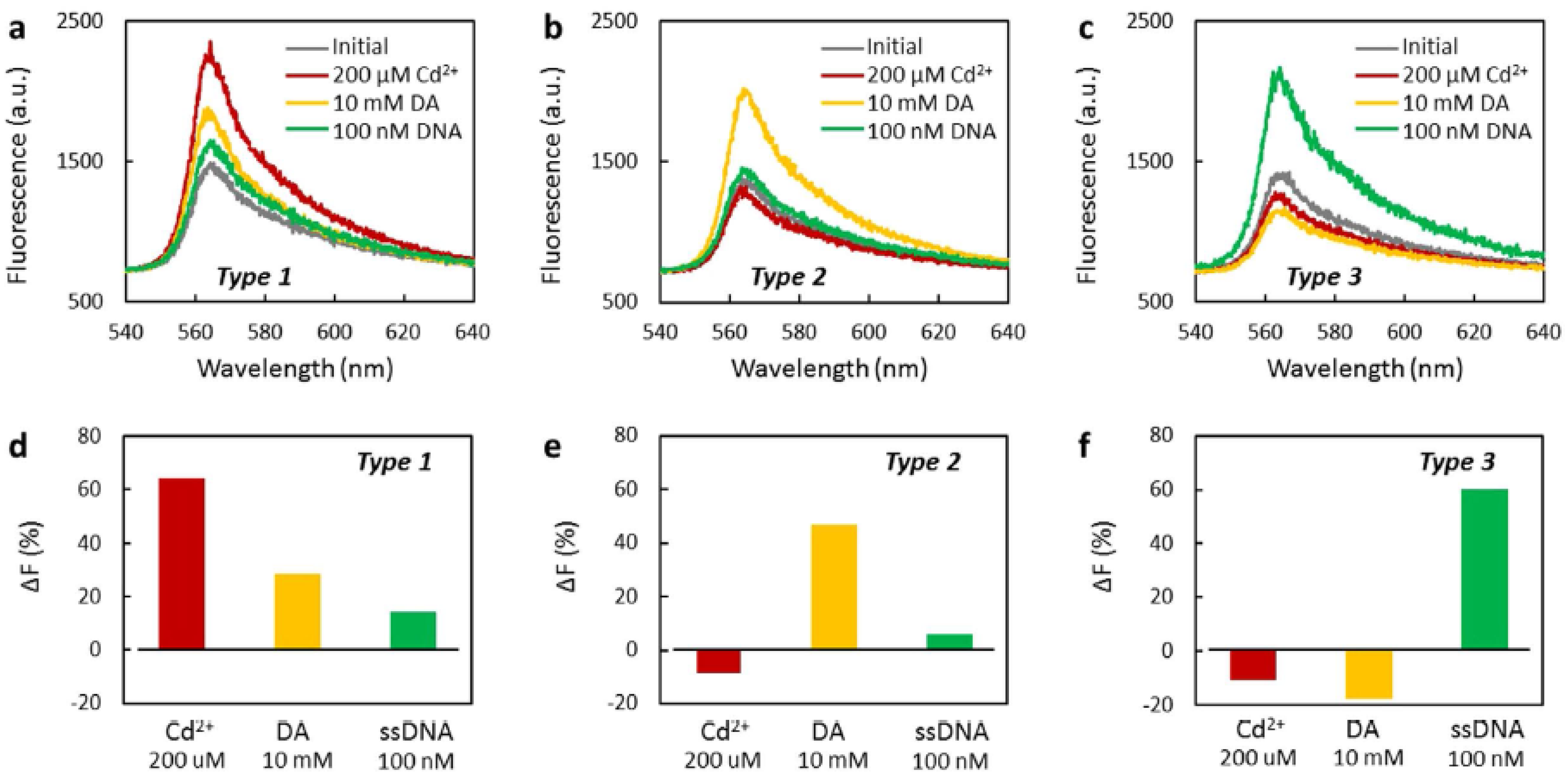
| Fluorescence | prGO | Etched MMF | Cd2+ ions, DA, ssDNA | - | - | - | [142] |
© 2017 by the authors; licensee MDPI, Basel, Switzerland. This article is an open access article distributed under the terms and conditions of the Creative Commons Attribution (CC-BY) license (http://creativecommons.org/licenses/by/4.0/).
Share and Cite
Hernaez, M.; Zamarreño, C.R.; Melendi-Espina, S.; Bird, L.R.; Mayes, A.G.; Arregui, F.J. Optical Fibre Sensors Using Graphene-Based Materials: A Review. Sensors 2017, 17, 155. https://doi.org/10.3390/s17010155
Hernaez M, Zamarreño CR, Melendi-Espina S, Bird LR, Mayes AG, Arregui FJ. Optical Fibre Sensors Using Graphene-Based Materials: A Review. Sensors. 2017; 17(1):155. https://doi.org/10.3390/s17010155
Chicago/Turabian StyleHernaez, Miguel, Carlos R. Zamarreño, Sonia Melendi-Espina, Liam R. Bird, Andrew G. Mayes, and Francisco J. Arregui. 2017. "Optical Fibre Sensors Using Graphene-Based Materials: A Review" Sensors 17, no. 1: 155. https://doi.org/10.3390/s17010155