
A Tactile Sensor Using Piezoresistive Beams for Detection of the Coefficient of Static Friction

 , ,
, , 
Abstract
:1. Introduction
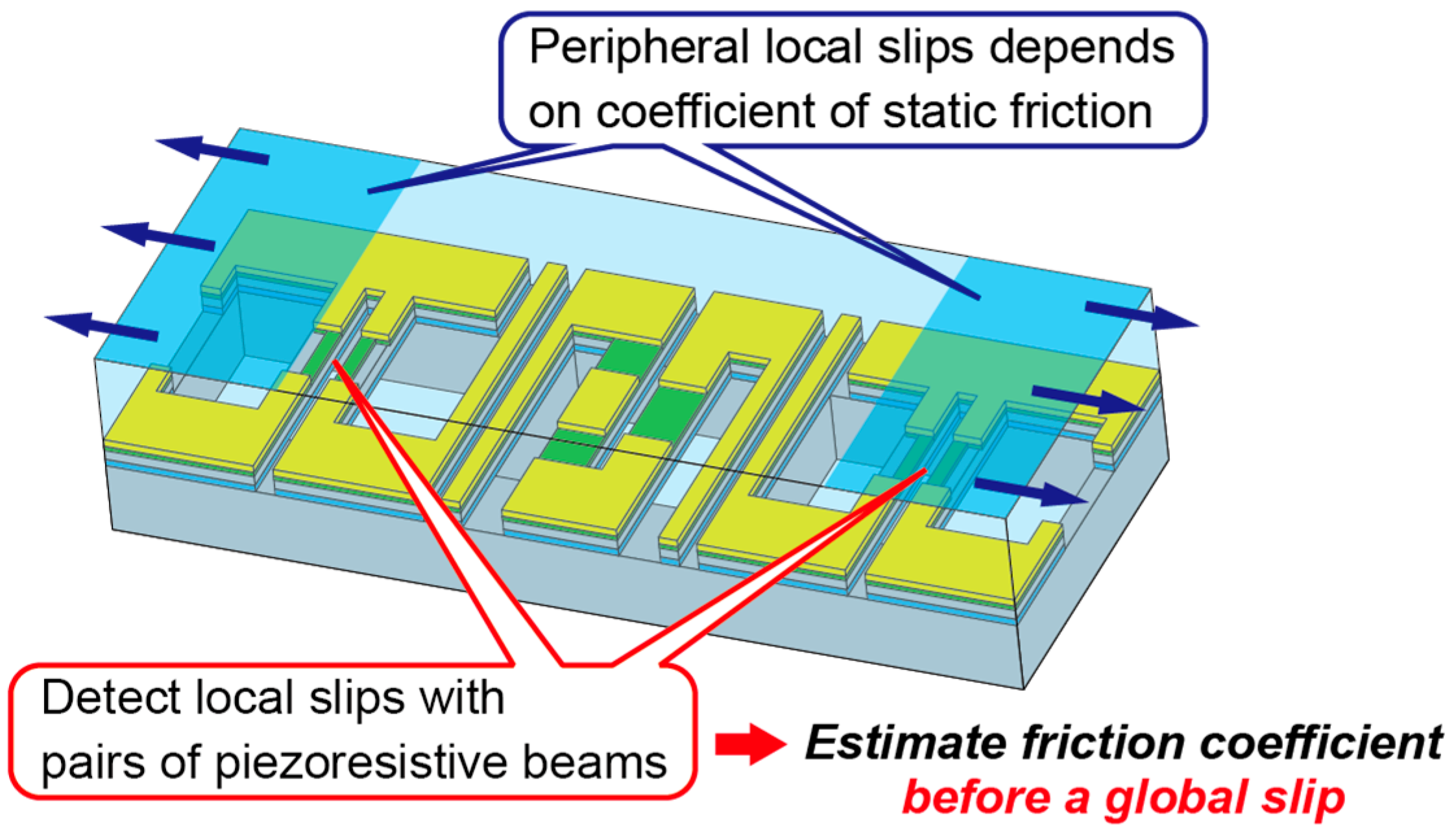
2. Principle
3. Design and Fabrication
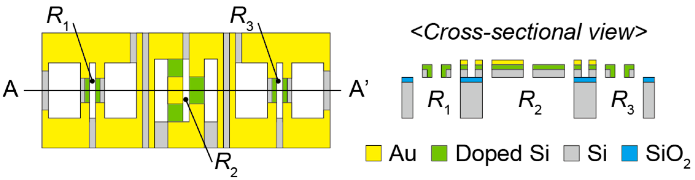
3.1. Sensor Design
3.2. FEM Simulation
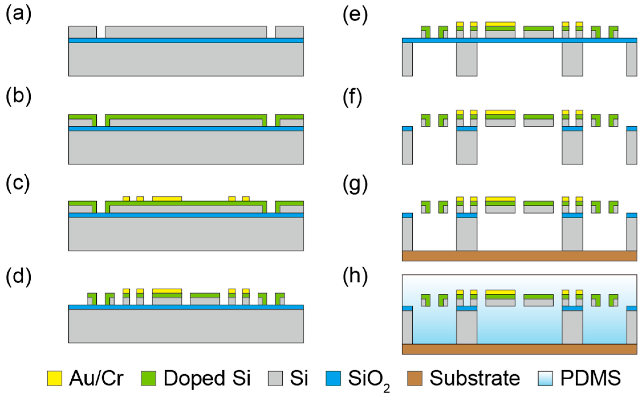
3.3. Fabrication Process
4. Experiment and Result
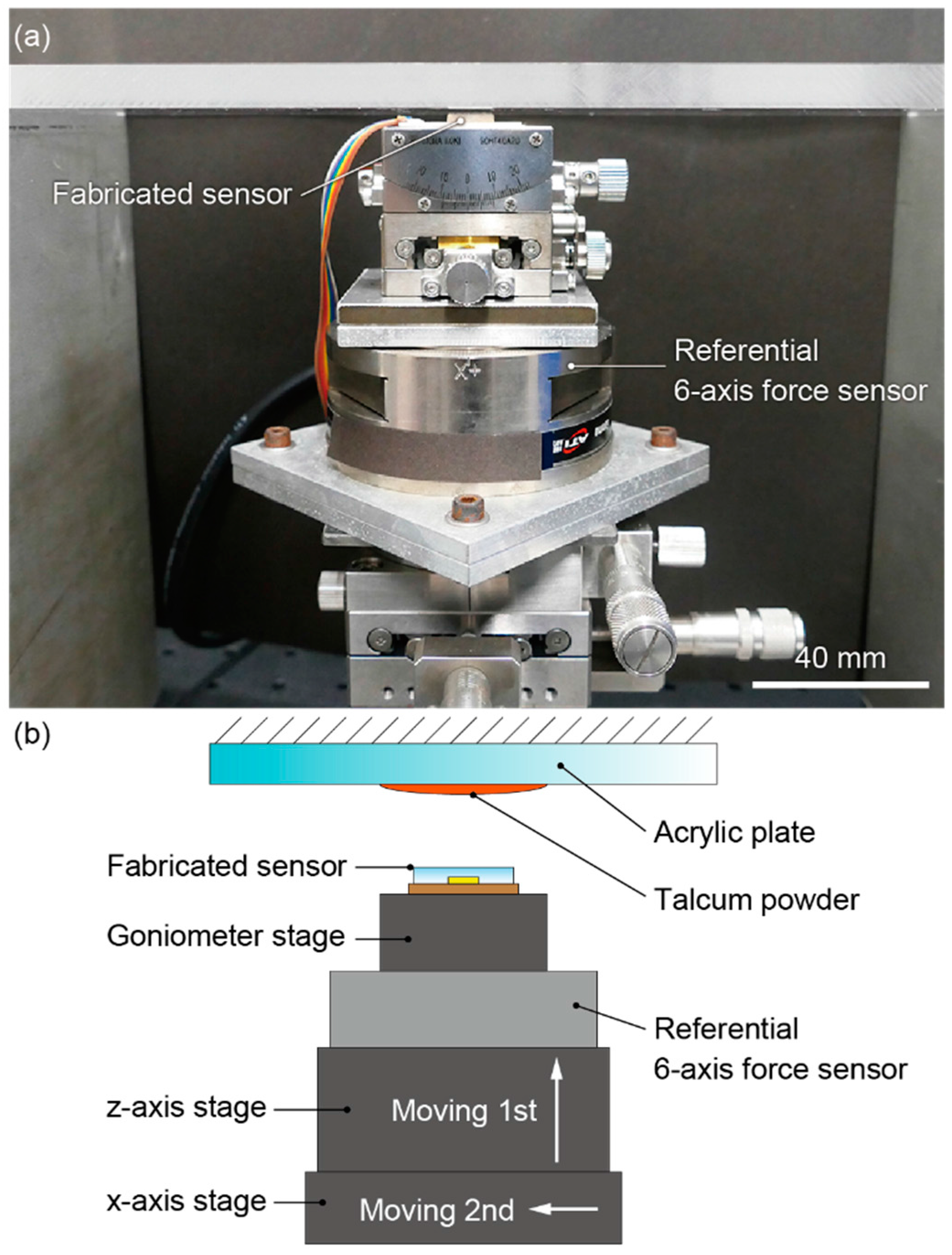
4.1. Setup and Trial
4.2. Response to Normal Force
4.3. Response to Friction Coefficient
4.4. Response to Shear Force
5. Conclusions
Acknowledgments
Author Contributions
Conflicts of Interest
Abbreviations
| MEMS | Micro Electro Mechanical Systems |
| FEM | Finite element method |
| ICP-RIE | Inductive Coupled Plasma-Reactive Ion Etching |
| PDMS | Polydimethylsiloxane |
| SOI | Silicon-on-insulator |
| SEM | Scanning Electron Microscope |
References
- Kappassov, Z.; Corrales, J.-A.; Perdereau, V. Tactile sensing in dexterous robot hands—Review. Robot. Auton. Syst. 2015, 74, 195–220. [Google Scholar] [CrossRef]
- Persson, B.N.J. Sliding Friction; Springer: Berlin, Germany, 1998; pp. 9–16. [Google Scholar]
- Johnson, K.L. Contact Mechanics; Cambridge University Press: Cambridge, UK, 1985; pp. 119–124. [Google Scholar]
- Maeno, T.; Hiromitsu, S.; Kawai, T. Control of grasping force by detecting stick/slip distribution at the curved surface of an elastic finger. In Proceedings of the IEEE International Conference on Robotics and Automation (ICRA 2000), San Francisco, CA, USA, 24–28 April 2000; pp. 3895–3900.
- Nguyen, T.-V.; Takahashi, H.; Nguyen, B.-K.; Matsumoto, K.; Shimoyama, I. Measurement of the pressure distribution during the onset of slip. In Proceedings of the IEEE Sensors 2012, Taipei, Taiwan, 28–31 October 2012.
- Ho, V.-A.; Hirai, S. Modeling and analysis of a frictional sliding soft fingertip, and experimental validations. Adv. Robot. 2011, 25, 291–311. [Google Scholar]
- Johansson, R.S.; Flanagan, J.R. Coding and use of tactile signals from the fingertips in object manipulation tasks. Nat. Neurosci. 2009, 10, 345–359. [Google Scholar] [CrossRef] [PubMed]
- Ho, V.-A.; Hirai, S. A novel model for assessing sliding mechanics and tactile sensation of human-like fingertips during slip action. Robot. Auton. Syst. 2015, 63, 253–267. [Google Scholar] [CrossRef]
- Nakamura, K.; Shinoda, H. A tactile sensor instantaneously evaluating friction coefficients. In Proceedings of the 11th International Conference on Solid-State Sensors, Actuators and Microsystems, Munich, Germany, 10–14 June 2001; pp. 1430–1433.
- Maeno, T.; Kawamura, T.; Cheng, S.C. Friction estimation by pressing an elastic finger-shaped sensor against a surface. IEEE Trans. Robot. Autom. 2004, 20, 222–228. [Google Scholar] [CrossRef]
- Yousef, H.; Boukallel, M.; Althoefer, K. Tactile sensing for dexterous in-hand manipulation in robotics—A review. Sens. Actuators A Phys. 2011, 167, 171–187. [Google Scholar] [CrossRef]
- Noda, K.; Hoshino, K.; Matsumoto, K.; Shimoyama, I. A shear stress sensor for tactile sensing with the piezoresistive cantilever standing in elastic material. Sens. Actuators A Phys. 2006, 127, 295–301. [Google Scholar] [CrossRef]
- Charalambides, A.; Cheng, J.; Li, T.; Bergbreiter, S. 3-axis all elastomer MEMS tactile sensor. In Proceedings of the 28th IEEE International Conference on Micro Electro Mechanical Systems (MEMS 2015), Estoril, Portugal, 18–22 January 2015; pp. 726–729.
- Xi, K.; Wang, Y.; Mei, D.; Liang, G.; Chen, Z. A flexible sensor array based on pressure conductive rubber for three-axis force and slip detection. In Proceedings of the IEEE International Conference on Advanced Intelligent Mechatronics (AIM 2015), Busan, Korea, 7–11 July 2015; pp. 476–481.
- Asano, S.; Muroyama, M.; Bartley, T.; Nakayama, T.; Yamaguchi, U.; Yamada, H.; Hata, Y.; Nonomura, Y.; Tanaka, S. 3-axis fully-integrated surface-mountable differential capacitive sensor by CMOS flip-bonding. In Proceedings of the 29th IEEE International Conference on Micro Electro Mechanical Systems (MEMS 2016), Shanghai, China, 24–28 January 2016; pp. 850–853.
- Takahashi, H.; Nakai, A.; Nguyen, T.-V.; Matsumoto, K.; Shimoyama, I. A triaxial tactile sensor without crosstalk using pairs of piezoresistive beams with sidewall doping. Sens. Actuators A Phys. 2013, 199, 43–48. [Google Scholar] [CrossRef]
- Nakai, A.; Morishita, Y.; Matsumoto, K.; Shimoyama, I. 6-axis force-torque sensor chip composed of 16 piezoresistive beams. In Proceedings of the 28th IEEE International Conference on Micro Electro Mechanical Systems (MEMS 2015), Estoril, Portugal, 18–22 January 2015; pp. 730–731.
- Kan, T.; Takahashi, H.; Nguyen, B.-K.; Aoyama, Y.; Takei, Y.; Noda, K.; Matsumoto, K.; Shimoyama, I. Design of a piezoresistive triaxial force sensor probe using the sidewall doping method. J. Micromech. Microeng. 2013, 23, 035027. [Google Scholar] [CrossRef]
- Gel, M.; Shimoyama, I. Force sensing sub micrometer thick cantilevers with ultra-thin piezoresistors by rapid thermal diffusion. J. Micromech. Microeng. 2004, 14, 423–428. [Google Scholar] [CrossRef]
- Isozaki, A.; Kuwana, K.; Tomimatsu, T.; Itoh, T. Photodiode with micro texture for improving sensitivity at large angle of incidence for particle sensors. In Proceedings of the 16th International Conference on Solid-State Sensors, Actuators and Microsystems (TRANSDUCERS 2011), Beijing, China, 5–9 June 2011; pp. 2050–2053.


© 2016 by the authors; licensee MDPI, Basel, Switzerland. This article is an open access article distributed under the terms and conditions of the Creative Commons Attribution (CC-BY) license (http://creativecommons.org/licenses/by/4.0/).
Share and Cite
Okatani, T.; Takahashi, H.; Noda, K.; Takahata, T.; Matsumoto, K.; Shimoyama, I. A Tactile Sensor Using Piezoresistive Beams for Detection of the Coefficient of Static Friction. Sensors 2016, 16, 718. https://doi.org/10.3390/s16050718
Okatani T, Takahashi H, Noda K, Takahata T, Matsumoto K, Shimoyama I. A Tactile Sensor Using Piezoresistive Beams for Detection of the Coefficient of Static Friction. Sensors. 2016; 16(5):718. https://doi.org/10.3390/s16050718
Chicago/Turabian StyleOkatani, Taiyu, Hidetoshi Takahashi, Kentaro Noda, Tomoyuki Takahata, Kiyoshi Matsumoto, and Isao Shimoyama. 2016. "A Tactile Sensor Using Piezoresistive Beams for Detection of the Coefficient of Static Friction" Sensors 16, no. 5: 718. https://doi.org/10.3390/s16050718