1. Introduction
Resistive sensor arrays are used in many applications such as tactile sensing [
1,
2,
3,
4,
5,
6], temperature sensing [
6], infrared sensing [
7],
etc. With resistive sensor arrays, wearable sensors such as wearable Braille sensors [
8], electronic skin devices [
5,
6,
9], and smart clothes [
10] have been proved to be useful for monitoring the activities of humans [
5,
6,
9,
10,
11,
12] and robots [
1,
2,
3,
4,
13]. For comfort wearing and precisely perceiving the physical parameter distribution of the sensing domain, interface electronics should not change the flexibility near the tactile resistive sensor array in smart clothes, and a readout circuit with long flexible cables would be a good choice to read out all elements in the array. Readout circuits of resistive sensor arrays with long flexible cables are also useful for robotic applications with limited space on their robot structures, for example the gripper [
5]. Thus, in tactile resistive sensor arrays, a large number of sensors and long flexible cables were necessary for sensing with better spatial resolution and flexibility in robotic operations [
1,
2,
3,
4,
13] and electronic skin devices [
5,
6,
9,
10,
11,
12]; however, these increased the interconnect complexity and degraded the performance of measurement accuracy in their readout circuits. Unfortunately, it is still a problem for the resistive sensor array with long cables to have a readout approach with good accuracy and a high readout rate.
In this paper, we propose a novel two-wire approach based on the zero potential method (ZPM) with a high readout rate for suppressing the cable crosstalk problem. It uses 2(M + N) wires, (M + N) op-amps in negative feedback, and 2M synchronous sampling channels in the resistive sensor array with M × N elements, keeping all sampling electrodes and all driving electrodes virtually at equipotential and reducing the cable crosstalk sufficiently.
2. Theoretical Analysis
Many readout approaches have been propose to suppress crosstalk in the tactile resistive sensor array. With detailed theoretical analysis and experimental results, a novel two-wire readout circuit with high accuracy, low cost and simple structure was presented in [
14]. The measurement error of the element being tested (EBT) in the resistive sensor array with long cables was affected by many factors such as parasitic parallel currents of the non-scanned elements [
14,
15], switch-on resistances of the multiplexers [
14], wire resistances of the long cables [
16,
17], and contact resistances between the tested cables’ plugs and the test circuits’ sockets [
16,
17]. The effect of parasitic parallel currents of the non-scanned elements would be more significant with a larger array size in the resistive sensor array. Different multiplexers had various switch-on resistances (
Rscs) which had resistances of several hundred milliohms to several hundred ohms [
16] and varied with the change of supply voltages. With the increase of the cable’s length, for example 500 mm [
5], wire resistances would increase. With the change of mechanical vibration and time, contact resistances would vary in the range of tens of milliohms to several ohms [
16,
17].
Many readout approaches were proposed to reduce the measurement error of the EBT caused by these factors.
Table 1 showed the comparison of different readout approaches. With the minimum circuitry of one sampling op-amp, the crosstalk caused by the non-scanned elements in the resistive sensor array was reduced with the readout methods including the voltage feedback method (VFM) [
18,
19] and ZPM [
15]. Also, the measurement error caused by the multiplexers’
Rscs was reduced by the readout methods based on VFM [
18,
19]. With the two-wire VFM [
16] and the two-wire setting non-scanned-driving-electrode equipotential (S-NSDE-EP) method [
17], the crosstalk caused by wire resistances and contact resistances was well suppressed by using two wires and one op-amp in negative feedback for every driving electrode and every sampling electrode. However, these methods could access only one sensitive element in the resistive sensor array at the same time, which caused their low readout rates. Based on VFM with one op-amp and one sampling channel, Speeter [
4] realized a 16 × 16 tactile sensing system for robotic manipulation with a scanning frame rate of 60 Hz.
Fast readout approaches of resistive sensor arrays made it possible for the robot to quickly respond to an external stimulus. With many synchronous sampling channels and many op-amps in negative feedback to access all elements on one column or one row at the same time, fast readout methods including the ZPM [
5,
6,
13,
20], the passive integrator method (PIM) [
1,
2], and the resistance matrix approach (RMA) [
12] were proposed without inserting additional component in the tactile resistive sensor array. Using the ZPM with many sampling channels and many op-amps in negative feedback, Yang
et al. [
6] realized a 32 × 32 temperature and tactile sensing array with a maximum scanning rate greater than 3000 elements per second. Luo
et al. [
13] realized a 16 × 16 flexible resistive sensor array with a scanning frame rate of 1.2 kHz. With high readout rates for using many sampling channels, the crosstalk caused by the adjacent elements in the resistive sensor array was suppressed by the ZPM-based one-wire readout circuit [
5,
6,
13,
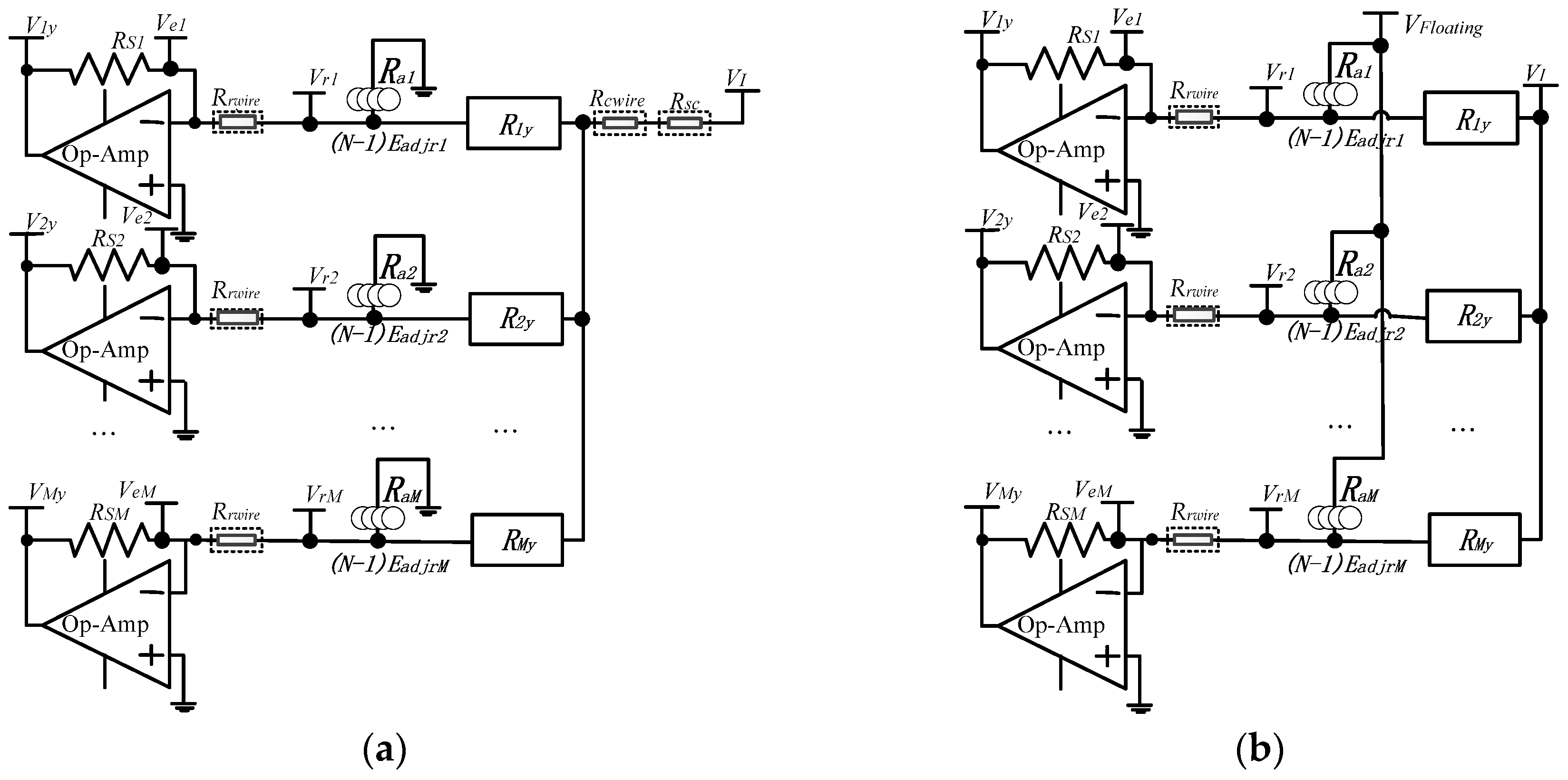
20] (the one-wire readout circuit hereafter) with its equivalent circuit model (Model A) as shown in
Figure 1a, using only one wire for both every driving electrode and every sampling electrode; the crosstalk caused by the long cables was partly suppressed by the ZPM-based part two-wire readout circuit [
14] (the part two-wire readout circuit hereafter) with its equivalent circuit model (Model B) as shown in
Figure 1b, using two wires for every driving electrode but only one wire for every sampling electrode. In Model A and Model B, all elements on one column or one row could be accessed at the same time by many synchronous sampling channels and fast readout rates were obtained. As shown in Model A, the equivalent effect adjacent resistance (
Rax, x = 1 to
M) of (
N − 1) row-adjacent non-scanned elements of every element (
Rxy,
x = 1 to
M,
y = 1 to
N) on the scanning column was connected to zero potential and its bypass effect was eliminated by ZPM. As shown in Model B, with the equivalent effect adjacent resistance (
Rax, x = 1 to
M), (
N − 1) row-adjacent non-scanned elements of every element (
Rxy,
x = 1 to
M,
y = 1 to
N) on the scanning column were connected to the non-scanning column electrodes with uncertain floating potentials.
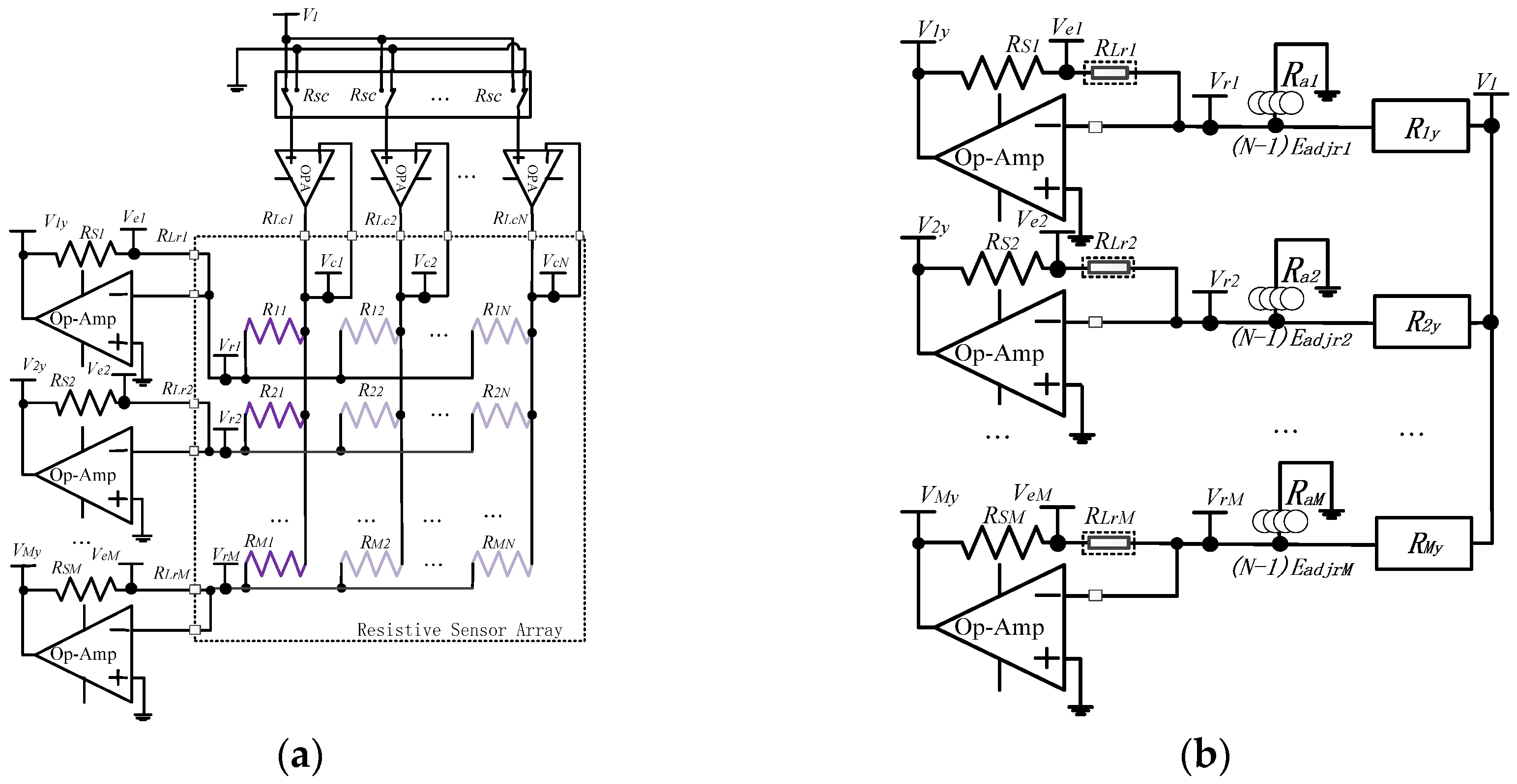
In Model A, the multiplexer’s switch-on resistance (Rsc) and the column resistance (Rcwire) including wire resistance and contact resistance existed on the scanning column electrode. Therefore, the voltage on the scanning column electrode was not equal to the set voltage (VI) and the crosstalk caused by multiplexers and column wires existed in the one-wire readout circuit. In Model B, the voltage on the scanning column electrode was equal to VI by using two wires and one op-amp in negative feedback for every driving electrode and then the crosstalk caused by multiplexers and column wires was suppressed by the part two-wire circuit. In Model A and Model B, with the row resistance (Rrwire) including wire resistance and contact resistance, only one wire was used for every sampling electrode. Thus, the voltage on every row electrode in the resistive sensor array was not at zero potential and the crosstalk caused by row wires still existed in these two circuits. Based on the ZPM with a larger number of sampling op-amps with a fast scanning rate, we proposed the full two-wire readout circuit to suppress the crosstalk caused by both the column resistances and the row resistances.
Figure 2 shows the proposed full two-wire readout circuit and its equivalent circuit model, in which two wires and one identical op-amp in negative feedback were used for both every sampling electrode and every driving electrode, where sampling electrodes and driving electrodes were row electrodes and column electrodes, respectively. As shown in
Figure 2a, all elements on the first column in the array were selected and accessed. On the column electrodes,
N 2:1 multiplexers had switch-on resistances (
Rscs). On all electrodes in the resistive sensor array, each column wire had the column resistance (
RLcy,
y = 1 to
N) and each row wire had the row resistance (
RLrx,
x = 1 to
M), with
RLcy and
RLrx having wire resistance and contact resistance. The virtual equipotential appearing at the two inputs of the op-amp on every driving electrode kept the scanning column electrode at the set voltage (
VI) and all other column electrodes at zero potential. The virtual equipotential appearing at the two inputs of the op-amp on every sampling electrode also kept each row electrode at zero potential, and the sampling electrode’s voltage (
Vrx,
x = 1 to
M) was equal to zero potential in the full two-wire readout circuit. Therefore, with the full two-wire readout circuit, two terminals of every non-scanned element had equal potential and no bypass current existed on all non-scanned elements. As shown in Model C, the bypass effect of the equivalent effect adjacent resistance (
Rax, x = 1 to
M) of (
N − 1) row-adjacent non-scanned elements (
Rnon-scanneds) of every element (
Vxy,
x = 1 to
M,
y = 1 to
N) on the scanning column were eliminated. Thus, the crosstalk caused by multiplexers’
Rscs and column resistances of the column wires was suppressed.
When
VI was applied to the scanning column electrode on the
yth column (
y = 1 to
N), the current on the EBT (
Rxy,
x = 1 to
M,
y = 1 to
N) of the
xth row was
VI/
Rxy. These currents would flow through each feedback resistance (
RSx,
x = 1 to
M) of all the
M row op-amps, producing an output voltage (
Vxy,
x = 1 to
M,
y = 1 to
N) equal to Equation (1).
Thus, we could read
M elements on one column at the same time. However, as shown in
Figure 2, the
RLrx caused the difference between the sampling electrode’s voltage (
Vrx = 0,
x = 1 to
M) and the voltage (
Vex,
x = 1 to
M) on the shared node of
RLrx and
RSx. Also, the row resistance would vary with both the change of the wire length and the change of the contact state for mechanical vibration and time variation. So the row resistance still affected the EBT’s measurement error.
As the currents on
Rxy,
RLrx, and
RSx were equal,
RSx were known, and
Vxy and
Vex could be measured by two synchronous sampling channels in the analog digital converter (ADC). So the equivalent resistance value (
Rxy) of the EBT in the full two-wire circuit could be calculated with Equation (2).
No RLrx existed in Equation (2). Thus, the crosstalk caused by row resistances of row wires was also suppressed in the full two-wire readout circuit.
From the above discussion, with 2M synchronous sampling channels, the proposed full two-wire readout approach can read M elements on the same column at the same time and suppress the crosstalk caused by multiplexers and cables completely.
4. Discussion
From
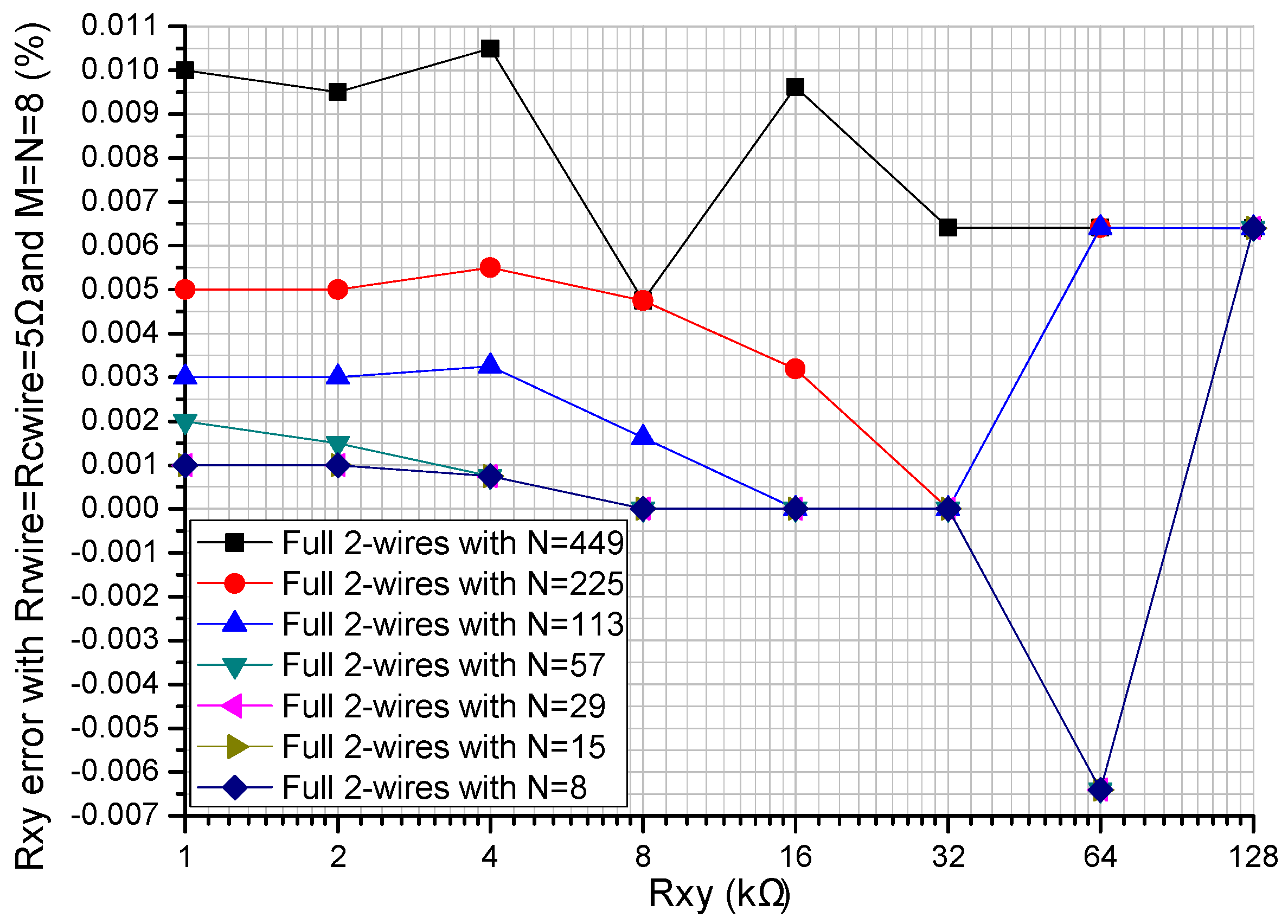
Figure 2, the sampling channels of the full two-wire readout circuit were double the amount of the sampling channels of the one-wire readout circuit and those of the part two-wire readout circuit. Therefore, the full two-wire readout circuit was not applicable for the resistive sensor array with a large number of sampling electrodes. From the results in
Figure 6, the column number had a negligible effect on the
Rxy errors of the full two-wire readout circuit. Thus, the full two-wire readout circuit was applicable for the resistive sensor array with a large number of driving electrodes.
From the results in
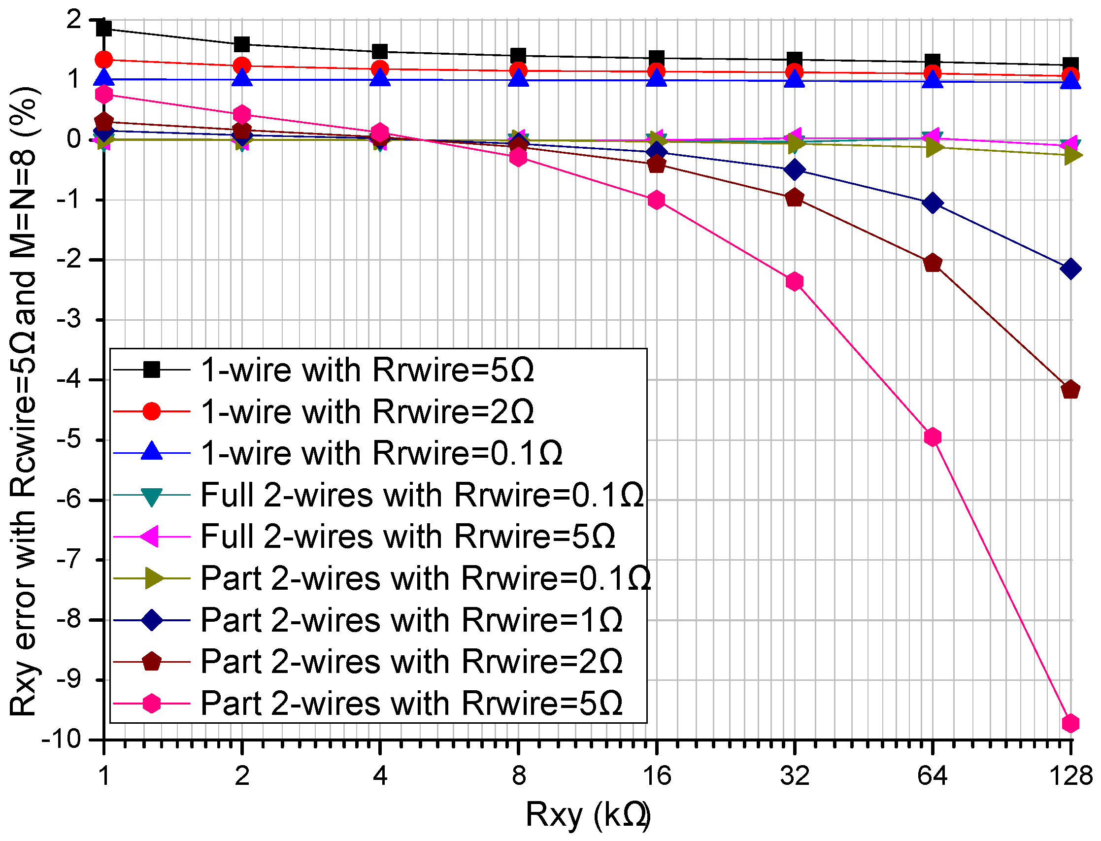
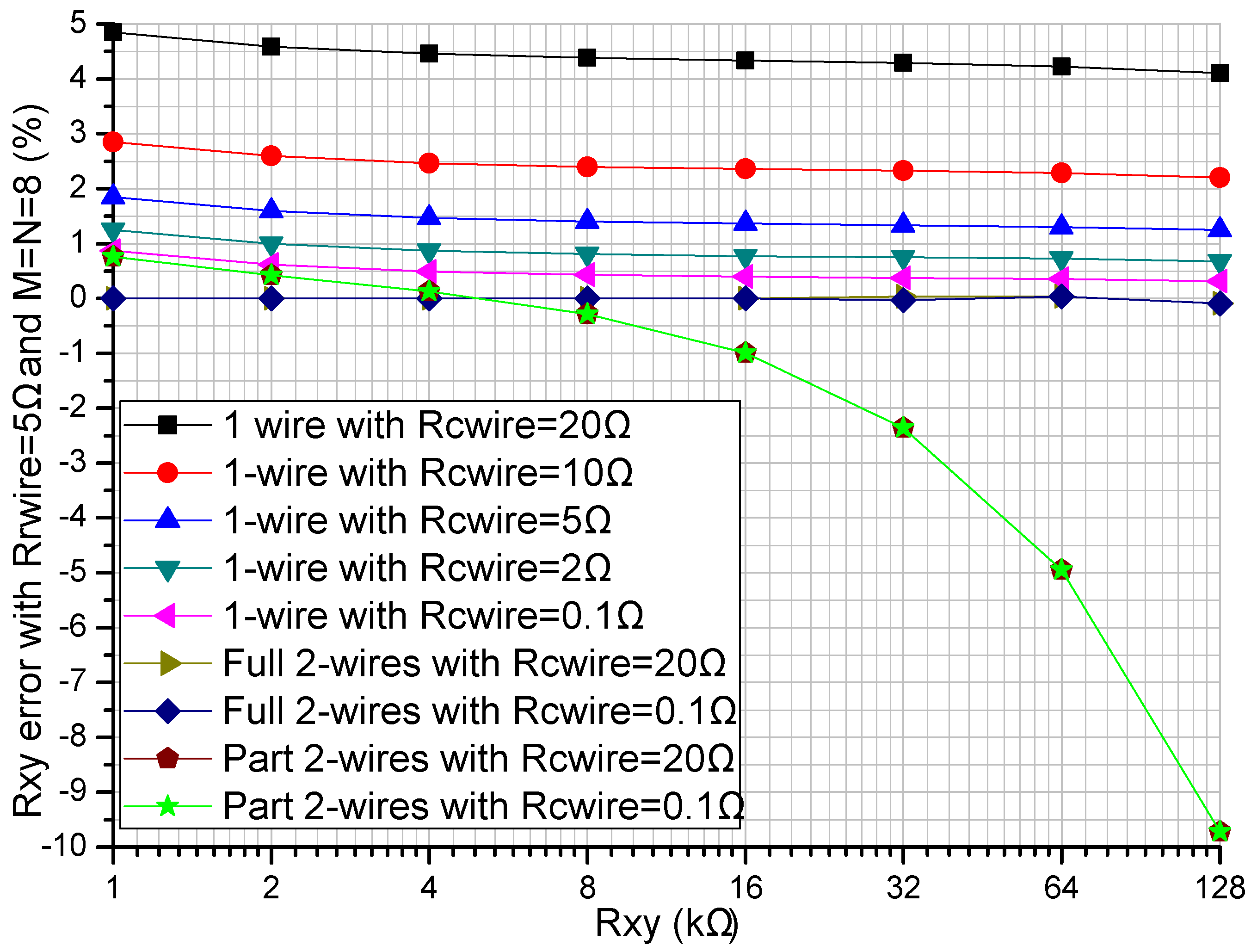
Figure 3 and
Figure 4, both the row resistance and the column resistance affected the
Rxy errors of the one-wire readout circuit with the simplest structure; with the increase of the row resistance and the column resistance, the
Rxy errors of the one-wire readout circuit increased. With a large row resistance, the part two-wire readout circuit with a relatively simple structure had large
Rxy errors even if the column resistance was small. With the increase of the resistance of
Rxy, both the one-wire readout circuit and the part two-wire readout circuit showed
Rxy errors with negative coefficients, which were more significant in the part two-wire readout circuit with a larger row resistance. The
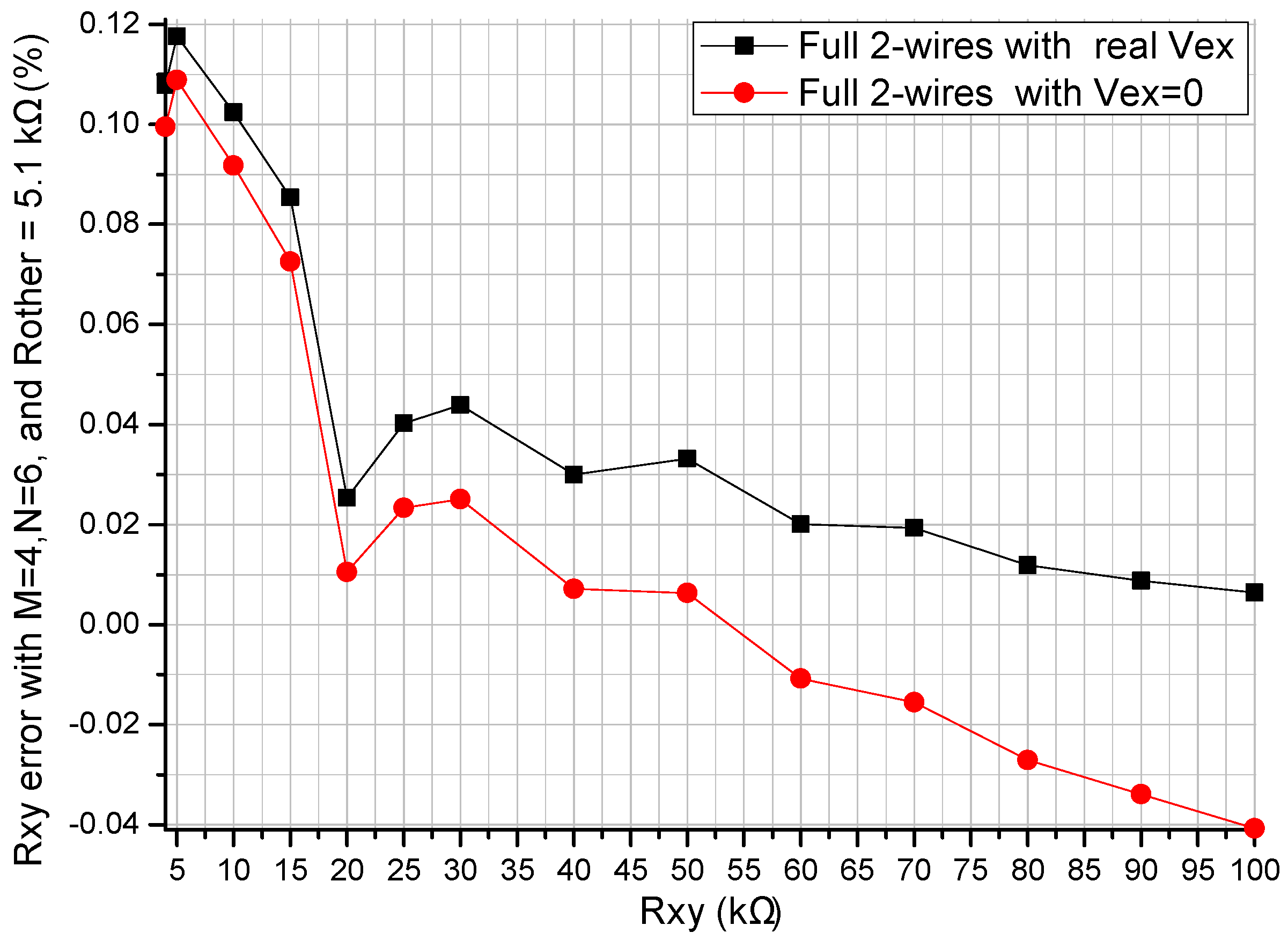
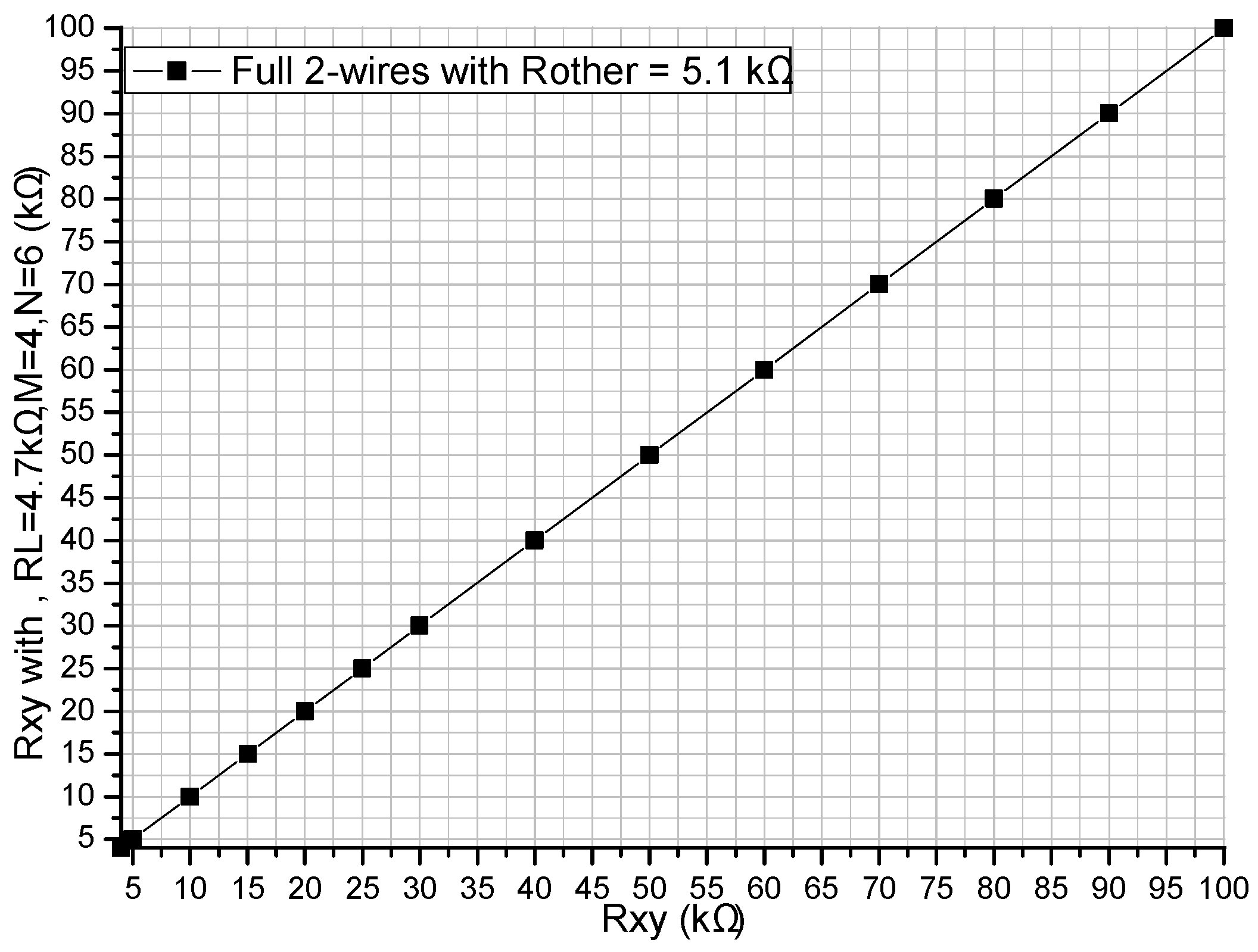
Rxy errors of the full two-wire readout circuit with the most complex structure were small enough to be negligible (less than 0.1%) even if both the column resistance and the row resistance were large. From the results in
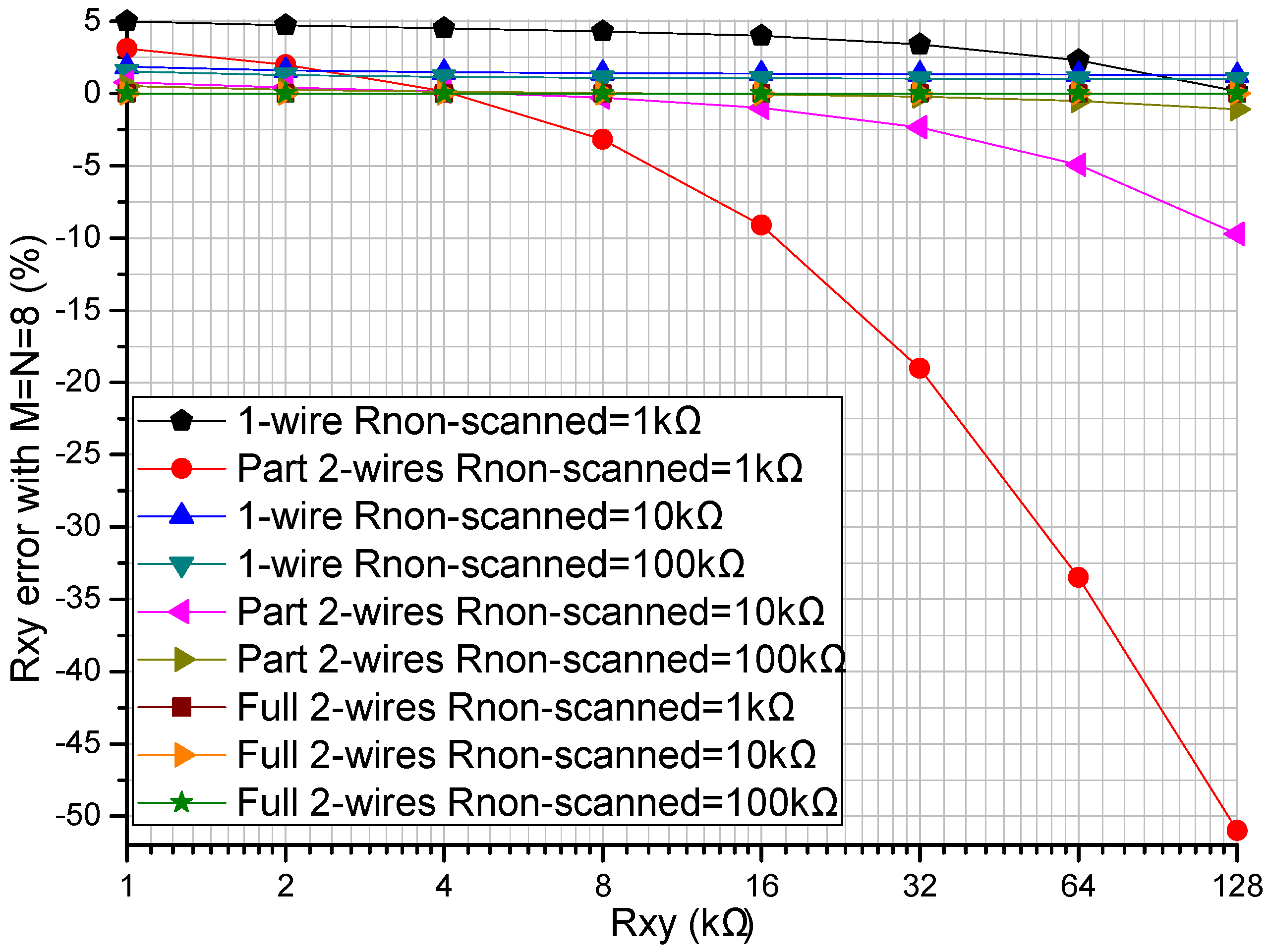
Figure 5, when the column resistance and the row resistance were large, the non-scanned elements had an obvious effect on both the
Rxy errors of the one-wire readout circuit and those of the part two-wire readout circuit, but the non-scanned elements had almost no effect on the
Rxy errors of the full two-wire readout circuit.
From
Figure 4 and
Figure 5, with a small row resistance, the non-scanned elements and the column resistance had almost no effect on the
Rxy errors of the part two-wire readout circuit, and similar results were also presented in [
14]. However, with a large row resistance, both the non-scanned elements and the column resistance affected the measurement accuracy of the part two-wire readout circuit. Thus, the part two-wire readout circuit had a good performance with a small row resistance. However, cable resistances existed in the row wires and the column wires, and the part two-wire readout circuit was not applicable for suppressing the crosstalk caused by long cables.
From
Figure 3,
Figure 4 and
Figure 5, we found that the performance of the part two-wire readout circuit was worse than that of the one-wire readout circuit when the row resistance was large. As for the reason, we found in
Figure 1 that all non-scanned driving electrodes of the one-wire readout circuit were connected to the zero potential while the non-scanned driving electrodes of the part two-wire readout circuit had uncertain floating potentials, which could break its ideal working condition. By connecting all non-scanned driving electrodes to the zero potential, it was possible for the part two-wire readout circuit to have a better performance even if the row resistance was large. From
Figure 2, the non-scanned driving electrodes of the full two-wire readout circuit were connected to the zero potential, which guaranteed its ideal working condition based on ZPM. Also, the voltage bias caused by the row resistance was measured with an additional sampling channel and it was used to calculate the precise resistance of the EBT. Thus, the full two-wire readout circuit had the best accuracy in the three circuits.
From
Figure 7 and
Figure 8, the full two-wire fast readout prototype circuit had a good performance in a wide range of the elements being tested. However, from the results in
Figure 8, there existed some particular points, for example at 20 kΩ of the EBT’s resistance, which might be caused by the non-linearity of the op-amp in the prototype circuit.
For quickly sensing external touch, it was necessary for resistive sensor arrays of the robots to have a readout approach with a high readout rate and good accuracy. Based on the ZPM with many synchronous sampling channels, the one-wire readout circuit and the part two-wire readout circuit were used to access all elements on one column in the array at the same time and fast readout rates, for example 1.2 kHz, were obtained [
6,
13]. A similar ZPM-based readout approach with a high read rate was also used in the proposed full two-wire readout circuit.
The effects of the zero potential op-amp’s gain on the readout circuits of resistive sensor arrays were analyzed in [
20,
23]. With a higher frequency response and a higher readout rate, the dynamic gain of the op-amp was smaller, which would degrade the measurement accuracy of the full two-wire readout circuit. For the same readout rate, there was a lower channel-switching frequency in the full two-wire readout circuit with more synchronous sampling channels than those in the readout circuits with only one sampling channel; then, a larger dynamic gain and a better accuracy could be obtained with the full two-wire readout circuit. However, one op-amp in negative feedback for every sampling electrode and every driving electrode was used in the full two-wire readout circuit and there was a risk of oscillation. By testing and obtaining the free-running oscillation frequency of the full two-wire readout circuit, special selection of the readout rate of the readout circuits could be used to avoid the risk of oscillation.
As stated above, many factors including the non-scanned elements, the driving electrodes’ number, the multiplexers’ switch-on resistances, and wire resistances and contact resistances of the long cables had less effect on the Rxy errors of the full two-wire readout circuit. Using the full two-wire readout circuit, more choices, including a larger number of driving electrodes, more types of multiplexers with larger switch-on resistances, and longer cables with larger wire resistances and contact resistances, could be realized in the resistive sensor array. Thus, the full two-wire readout circuit with a fast readout rate and good measurement accuracy is useful for many applications such as flexible electronic skin, tactile sensing applications, smart clothes, etc. However, in the M × N resistive sensor array, many conditions including 2(M + N) wires, (M + N) op-amps, and 2M synchronous sampling channels are necessary for the proposed circuit. Therefore, the proposed circuit has a larger cost, a larger power consumption, and a more complex structure than the one-wire readout circuit and the part two-wire readout circuit. With a small row resistance, including the wire resistance and the contact resistance, in the resistive sensor array, the part two-wire readout circuit with a low cost and simple structure also has a fast readout rate and good measurement accuracy.
It should be noted that all analyses and results were right under the assumption that the column op-amps had sufficient driving ability and the row op-amps had very big input impedances on the inverting inputs. If the row op-amp did not have a very big input impedance or the elements in the resistive sensor array had very big resistance values, the current on the EBT would not be equal to the current on its feedback resistance. Thus, the ideal work condition was destroyed in the proposed full two-wire readout circuit and the EBT’s measurement error would be significant.


