1. Introduction
One of the aspects that characterizes the development of a society is its energy consumption in all of its forms, where the amount of consumption is steadily increasing. As energy use increases, illegal electricity usage causes an undue additional load on the power distribution system [
1]. Therefore, detecting and localizing illegal electricity usage is a significant challenge for power delivery companies in many countries [
2,
3]. For example, the Minister of Energy and Natural Resources in Turkey has stated that the illegal usage of electricity constitutes 19% of the total electricity consumption in Turkey [
4]. The same problem exists in Iran [
5], and even Mongolia is now seeking an optimal solution for remote detection of illegal electricity usage [
6]. Low voltage power delivery system includes power transformer and subsystems. Electrical voltage supported from the electrical source is decreased because of the power transformer and is transmitted by low voltage transmission line to each of the subsystems. The subsystems include energy users and energy meters. The subsystem then transmits electricity from a note to local users. Illegal electricity usage may exist on the user side of the subsystems, on the outside of nodes or on the low voltage transmission line. Electricity could be used illegally in the four ways. One way is switching of energy cables at the energy meter box. Other ways are use of external phase before the energy meter terminals, use of fixed magnet and use of mechanical objects [
7].
A number of detection methods for illegal electricity usage have been researched in recent years. The detection methods of illegal electricity usage are classified into two kinds. These are off-line and real-time methods. Off-line detection methods are based on statistical tools, which use the measurement data of energy users over several days and years. Remote detection methods in real time are classified as follows: Smart meter method, high frequency signal processing method, and inspection robot based methods [
8]. Smart meter based remote detection methods are based on the current differences between two energy meters [
4]. High frequency signal processing based remote detection method uses a disconnection conception of energy users. There, illegal electricity usage can be detected by measuring the line impedance when the power distribution system of all users are disconnected and then a low-voltage signal having a high frequency component is transmitted to the power distribution system [
5]. Recently, inspection robot-based detection systems are widely utilized in power line measurement [
9,
10,
11,
12,
13,
14].
In this paper, we propose an illegal electricity detection system using a new power line tracking algorithm for mobile sensing based on an inspection robot and smart meters.
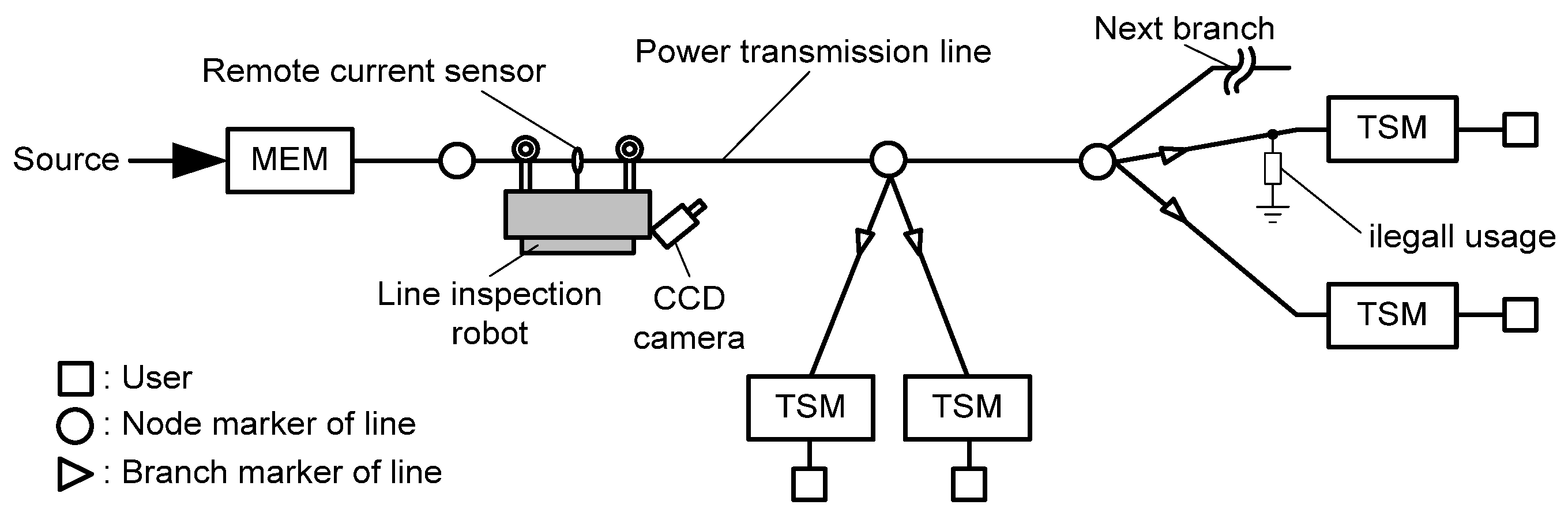
Figure 1 illustrates an illegal electricity detection system using an inspection robot and smart meters.
In this detection system, the main energy meter (MEM) and the terminal smart meter (TSM) are installed on the starting node and on the final end of each electrical user, respectively. MEM measures the total energy of all electrical users. At the same time, TSM measures the energy usage of each user and transmits the measured energy value through the power line communication system. If an illegal electricity usage occurs on the power delivery system, the measured value of MEM and the summation of each TSM measurements will not be equivalent. In this case, the detection system begins a process by switching the status of TSMs, as shown in
Figure 1b. The switch of a TSM can be either turned on or off by the command of a control block with a high frequency component. The voltage sag is converted to a normal voltage by AC/AC converter, which is created by the switching frequency. If MEM measures some amount of current, even though the user’s currents were switched off by TSMs, that means illegal electricity usage through that power line. But, when a user’s currents are switched on by a TSM, the measured current of the MEM represents the total current of the power distribution system. Therefore, an inspection robot can remotely measure those two kinds of currents. The inspection robot can crawl and move under the transmission line and detect obstacles using camera and other sensors. When the inspection robot detects an obstacle, it can pass through the obstacle [
10,
11,
12,
13,
14].
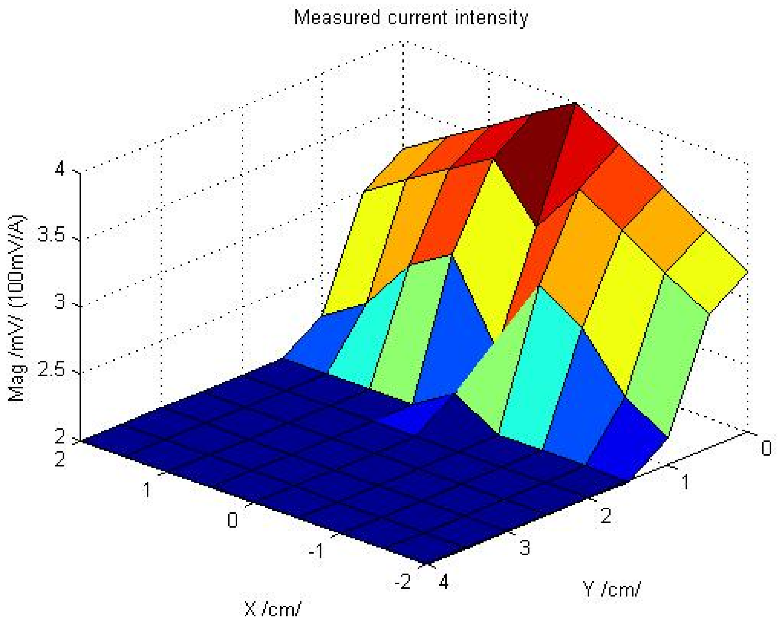
Figure 2 shows the working environment of a detection system with an inspection robot.
The inspection robot starts to move away from a MEM and its motion is continued even if an illegal current is measured and detected. To detect and localize of illegal electricity usage, the illegal current should be separated from measured current using the inspection robot.
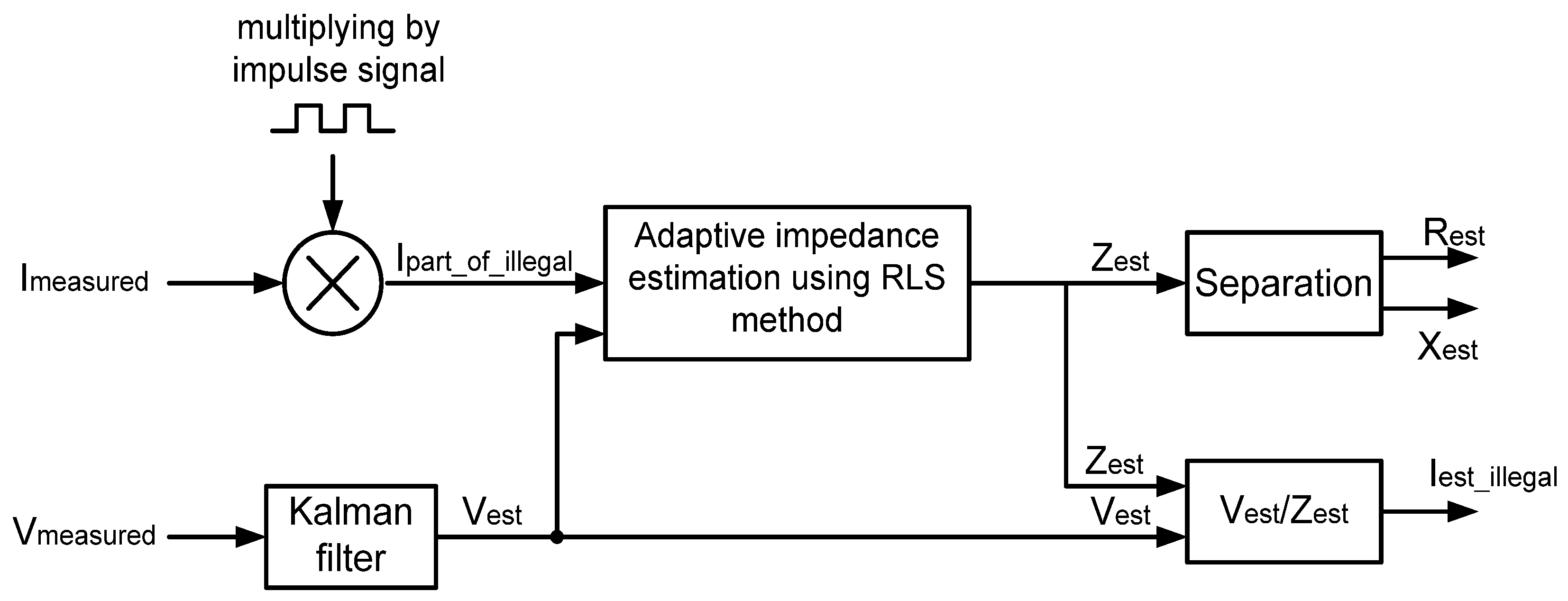
Figure 3 shows the signal process to separate the illegal current.
When the measured current from the inspection robot is multiplied by an impulse signal, the illegal current section can be extracted. In this case, the impulse signal becomes active when users are disconnected by TSMs. In addition, the measured current can be multiplied by another active impulse signal when users are connected by TSMs. In this condition, multiplied current represents the total component of current. Furthermore, the measured voltage from the power delivery system is filtered by a Kalman filter (KF) from the noise of measurement equipment. Because a KF generates efficiency response for sinusoid signals with constant frequency. After that, the adaptive impedance is estimated by values of multiplied illegal current section and filtered voltage using Recursive Least Square (RLS) method. For an estimation, the impedance values of illegal electricity usage should be calculated using measured current and filtered voltage when impulse signal is active. It is assumed that illegal electricity usage is not changed and is constant. Then, calculation of the illegal current is possible using an estimated impedance and filtered voltage.
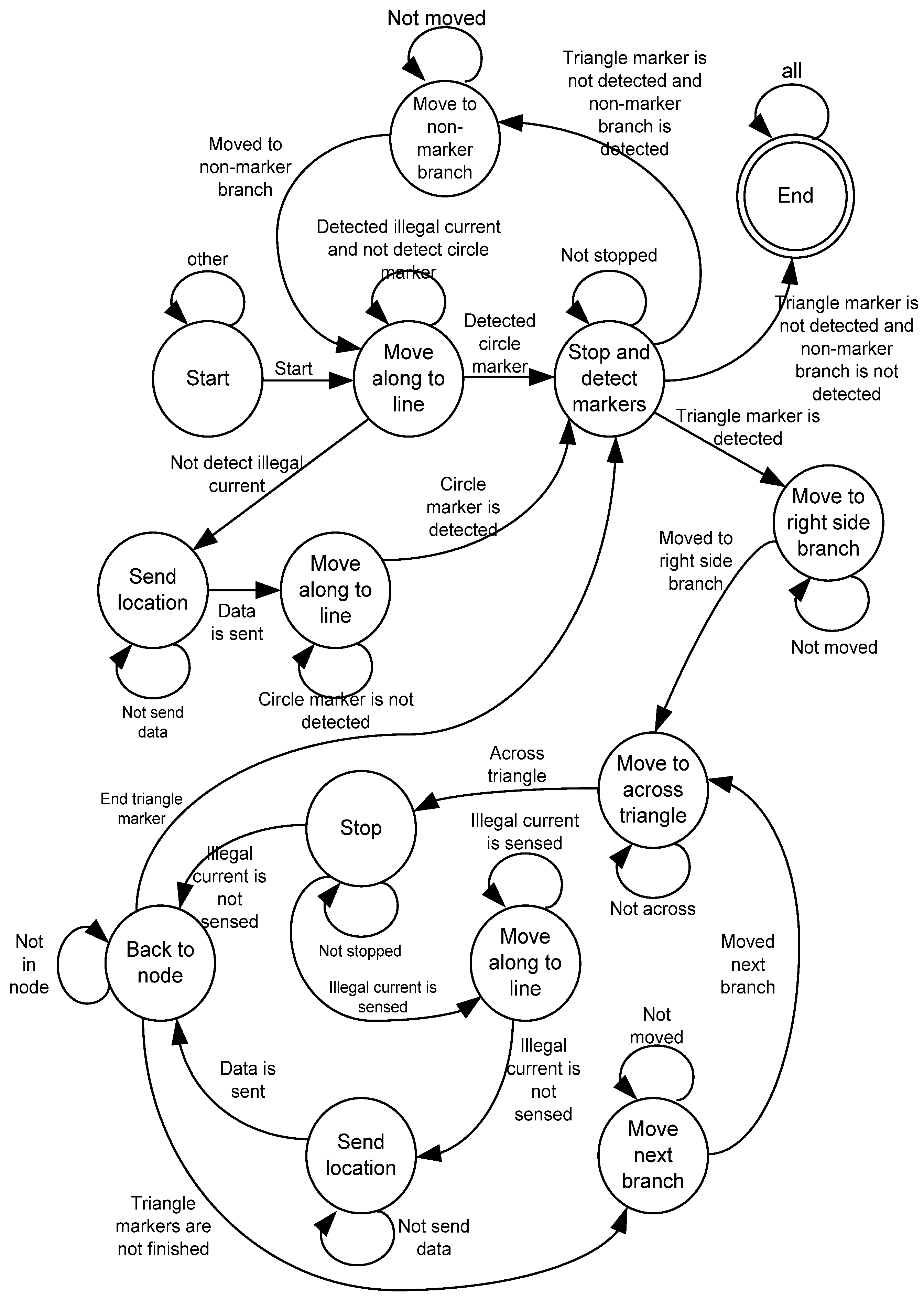
If the measured current from the inspection robot has an illegal current section, the robot continues its motion towards a node marker. When the robot arrives at the node marker, it detects all of the triangle branch markers and moves to the right-most side of the branch by using its CCD camera. The value of illegal current is calculated on the triangle marker of the passed branch. If the illegal current is detected, the robot continues its motion to pass the branch until arrival at the exact location of illegal electricity usage [
9].
Used in this way, the exact location of illegal electricity usage can be transmitted by the robot. After transmission, the robot goes back to the node and checks the next branch.
If the illegal current is not detected on the triangle marker of the passed branch, the robot goes back to the node and checks the next branch. When all branches with triangle markers are examined, the robot goes to a non-marker branch and repeats its process. The detection process terminates when there is no branch having any markers, which is equivalent to a full coverage inspection of the entire power delivery system. The finite state diagram of the inspection robot is shown in
Figure 4.
When the above mentioned environment is used for remote detection of illegal electricity usage, there is a very important aspect of exact tracking on the overhead power line. This exact tracking is the main reason for correct measurement.
In particular, automatic power line detection and tracking are new topics in the world. This paper presents a new power line tracking algorithm for mobile sensing and detection of illegal electricity usage based on an inspection robot.
2. Inspection Robot Based Line Tracking Method
In order to remotely detect illegal electricity usage, the exact tracking of electric transmission lines and accurate measurements are very important. To do accurate tracking, it is necessary to save the distances of the remote current sensor and the electric transmission line with a constant value. For the tracking process, the distances of the remote current sensor and the electric transmission line are measured by various types of sensors. For example, there are ultrasonic sensors, proximity sensors, and digital cameras. In this case, the measurement error is generated by sensors, which is inconvenient for the tracking process.
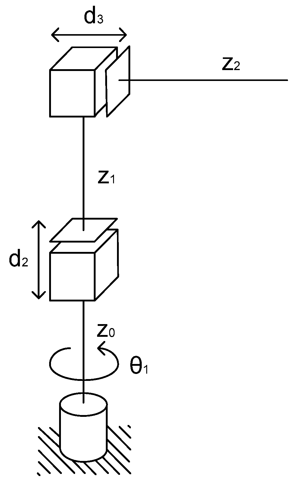
The electric transmission line tracking algorithm in this paper consists of several purposes. The tracking algorithm should predict measurement error and correct movement of tracking process for correct current measurement. In order to consider a new tracking method, measurements are executed with the following assumption. We assume that a mobile robot and manipulator are used for the tracking process, the manipulator is placed on the mobile robot. In this tracking system, various type manipulators can be used. However, in this paper, a cylindrical manipulator is selected, which is consistent for movement of tracking electric lines and their swing, and is very easy to use [
15]. In addition, it is quick to show simulation results of the proposed tracking algorithm. The cylindrical manipulator is shown in
Figure 5.
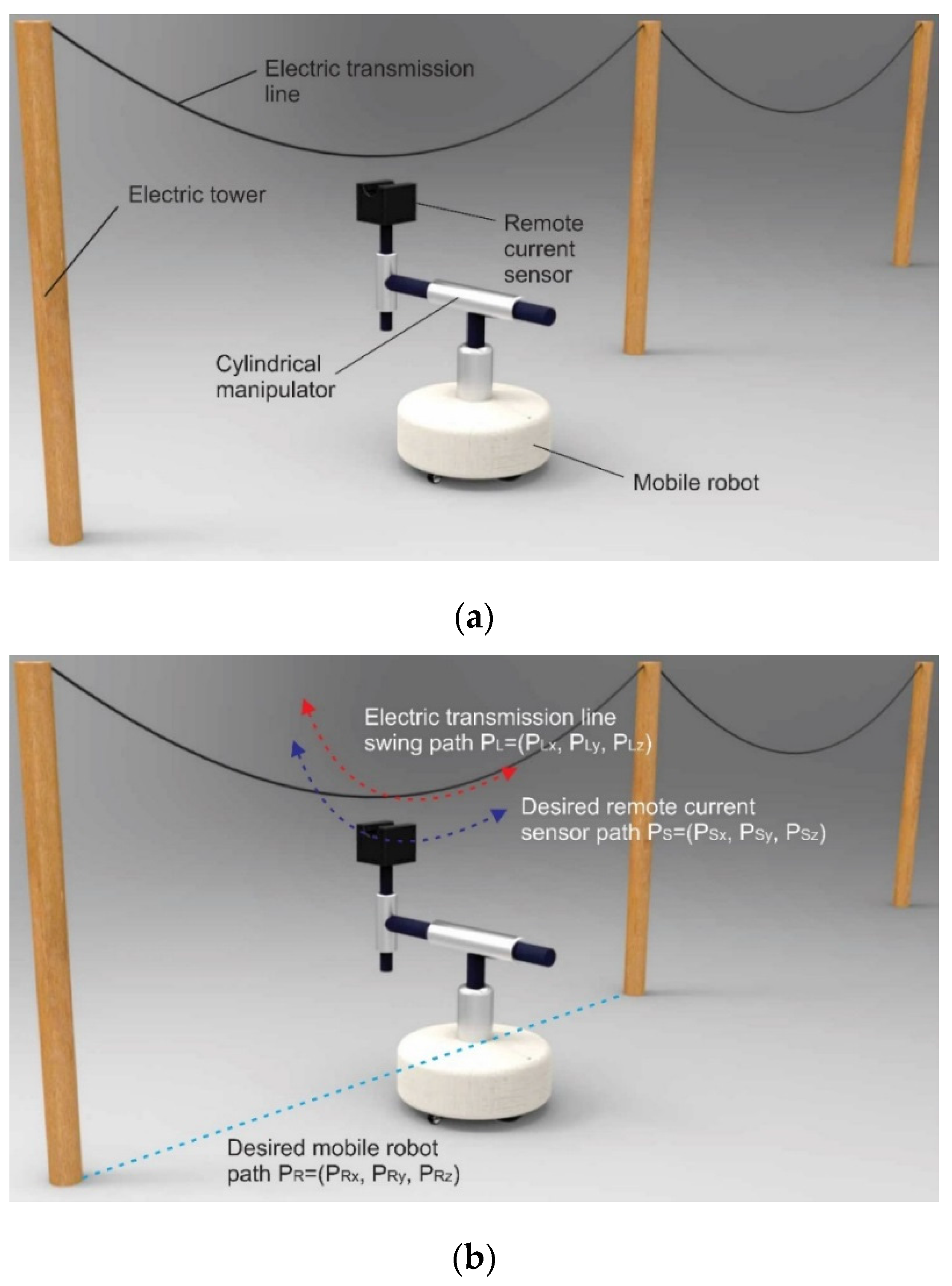
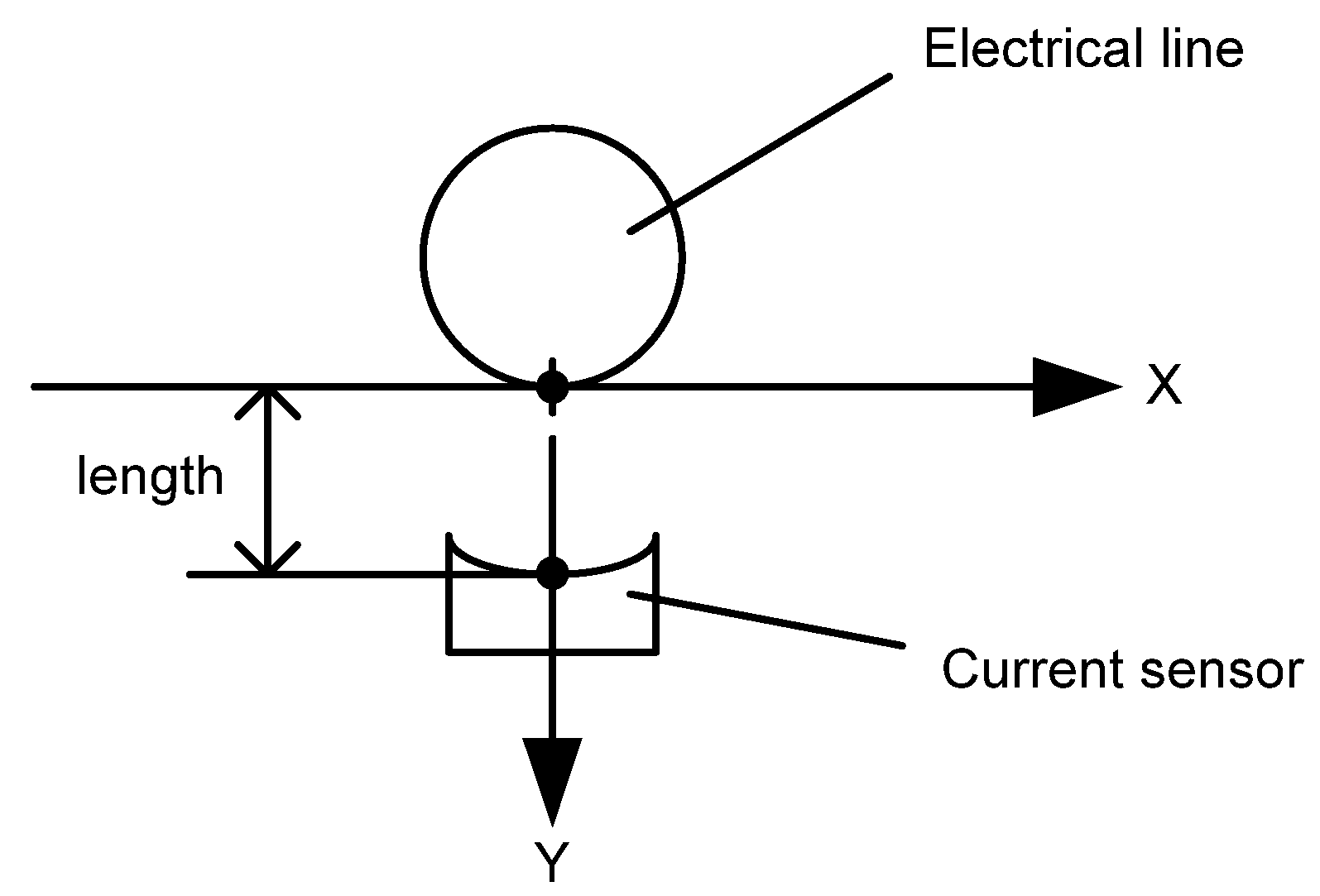
Furthermore, the remote current sensor is placed on the vertical actuator of the cylindrical manipulator, which measures electric current value during the tracking process. The swing of electric transmission lines depends on environmental conditions, temperature and wind speed, and the trajectory is different in such conditions.
Figure 6 shows an example of the tracking system described. The tracking system consists of an electric tower, electric transmission line, remote current sensor, distance sensors, cylindrical manipulator, and a mobile robot. The height of the tower for electric transmission lines and the distance between the two towers depends on construction, type of line, voltage level, environmental conditions, and so on. However, the electric wire depends on transmission power and voltage level. The current sensor on the tip of the cylindrical manipulator should be placed near the electric wire with current, where it is possible to remotely measure the electric current [
16,
17]. In addition, the mobile robot moves along the electric line planned path using several kinds of sensors, and is called an inspection robot [
11].
The planned path of the mobile robot, the electric line swing and the desired remote current sensor path are shown in
Figure 6b. Distance sensors would be placed on the tip of the cylindrical manipulator, which measures the distance between the current sensor and the electric wire. In addition, PL is the electric line position coordinate, Ps is the remote current sensor position coordinate, and PR is the mobile robot position coordinate. In this system, we assume that:
where: is the Z coordinate of the electric line; is the Z coordinate of the remote current sensor; is the Z coordinate of the mobile robot; and is the Y coordinate of the mobile robot.
Also, noise is generated in the real system during measurement of P
Lx and P
Ly. Therefore, the input coordinates are:
where:
is the X coordinate of the electric line;
is the Y coordinate of the electric line;
is the measurement noise of the X coordinate;
is the measurement noise of the Y coordinate;
is the X coordinate of the electric line with measurement noise; and
is the Y coordinate of electric line with measurement noise.
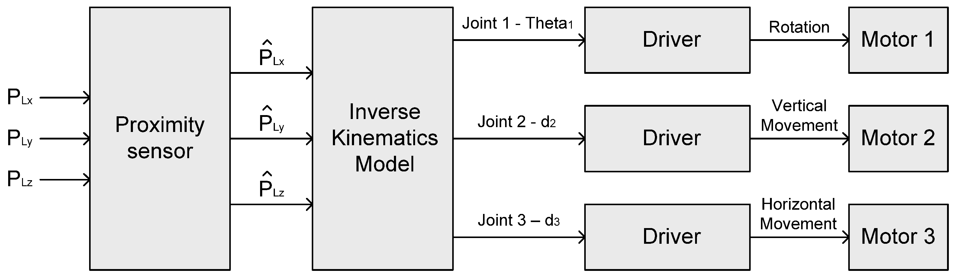
The main objective of the tracking system is to carry out accurate remote current measurements. In order to measure current, when the electric line swings due to wind, the current sensor could follow the electric line. To move to the desired position, the control system for the cylindrical manipulator has to get the coordinate of the movement position from input. Input coordinates are passed to the proximity sensor model. Then, the coordinates with the measurement noise are transferred to the inverse kinematics model. The inverse kinematics model for the control system can calculate the motion angle of the first joint, the displacement of the next two joints and the offsets of joints, and then put in the calculated parameters to the drivers of the motor. Furthermore, the drivers can control each joint motor. The structure of the control system is shown in
Figure 7. Motor 1 is installed on the first joint, which can carry out the rotation of the manipulator. However, Motors 2 and 3 are installed on the vertical and horizontal actuator, respectively.
In order to determine parameters of movement, the inverse kinematics equations of the cylindrical manipulator can be used [
18]. In our tracking system, the inverse kinematics equations are:
where:
are the electric line coordinates of desired position with measurement noise;
is the angle of Joint 1;
are the joint motions for 2 and 3;
are the joint offsets for 1 and 2.
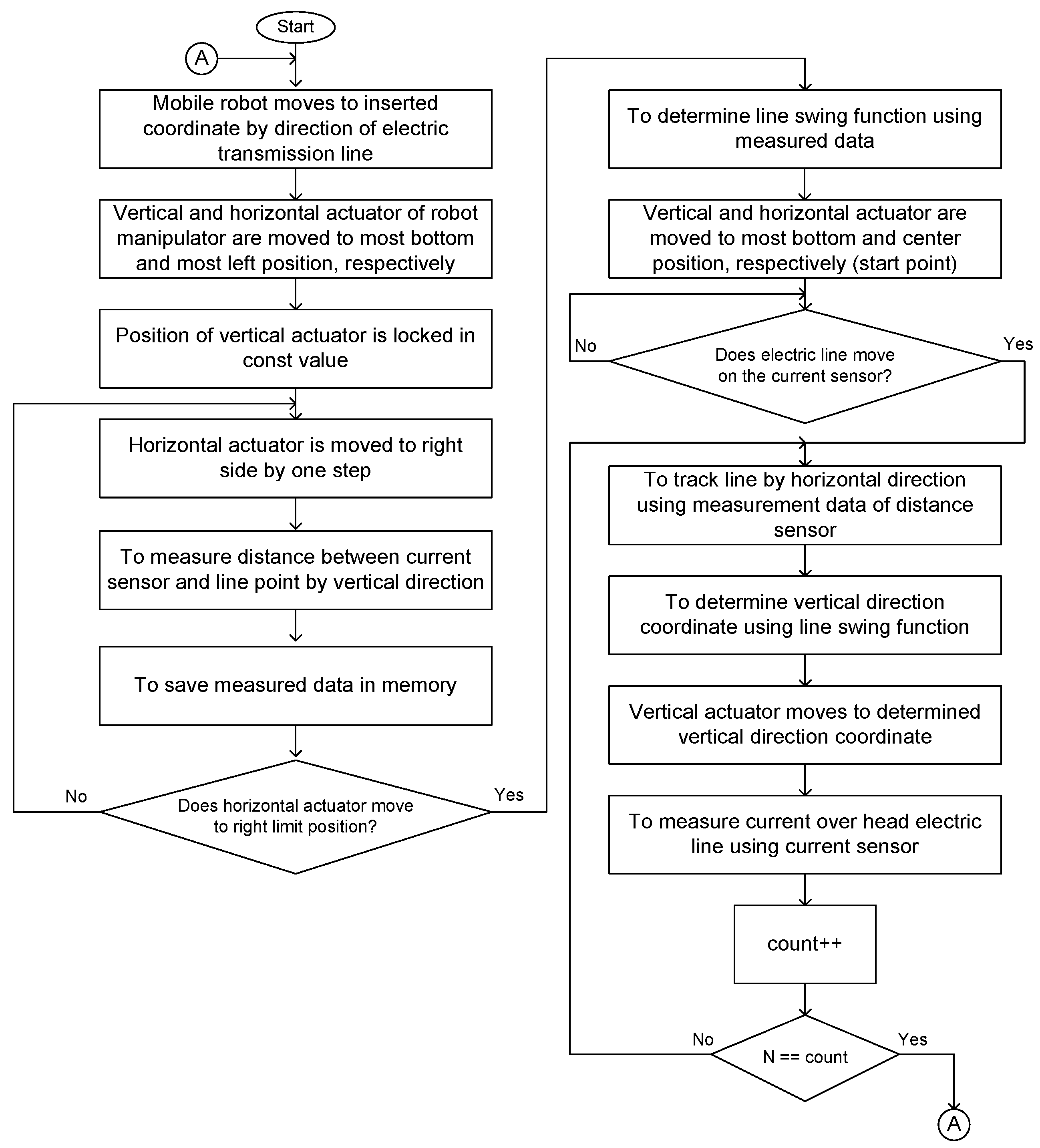
Next, the line tracking algorithm is described. The line tracking algorithm is shown in
Figure 8. First of all, the mobile robot travels along the electric line and stops at the target coordinate. Then, the vertical actuator movement of the manipulator on the mobile robot is held at a constant value. Furthermore, the horizontal actuator is moved to a horizontal direction. During this horizontal movement, distance measurements between the remote current sensor and the electric line are executed using proximity sensors by vertical direction, and the measurement data is saved. Now, the line swing function can be fitted using gathered measured values, which can represent the swing trajectory of the electric line and movement. The line swing function is mathematical description, which is represents that how conductor of electric line hangs due to wind load. In this algorithm, the fitting process can be implemented by parabolic and circle curve fitting to 2D points. Curve fitting is the process of constructing a curve, or mathematical function, which has the best fit to a series of data points, possibly subject to constraints [
19]. The type of curve fits can be divided into three main categories: Least squares curve fits, nonlinear curve fits, and smoothing curve fits.
So, it is necessary to fit a circle to 2D points. Therefore, fitting a circle can be used in this algorithm. Given a set of points
, m ≥ 3, fit them with a circle
where (a, b) is the circle center and r is the circle radius [
20].
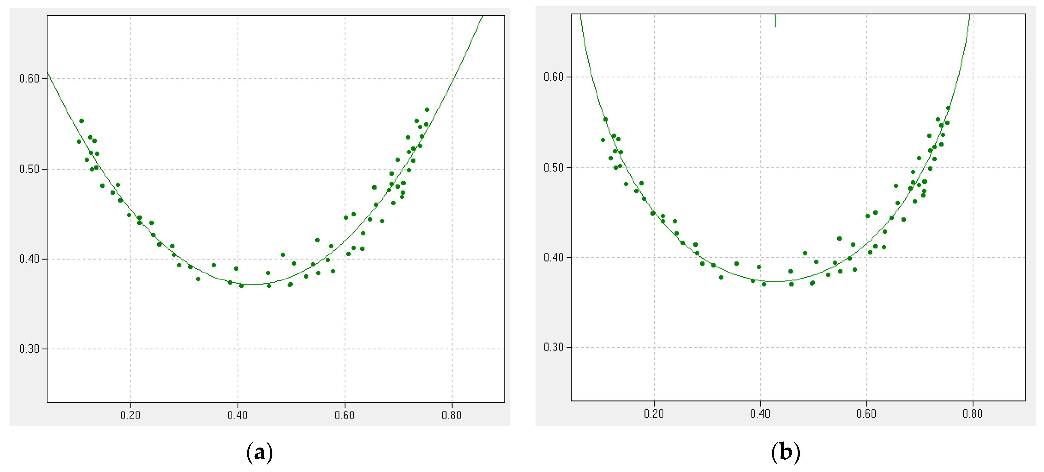
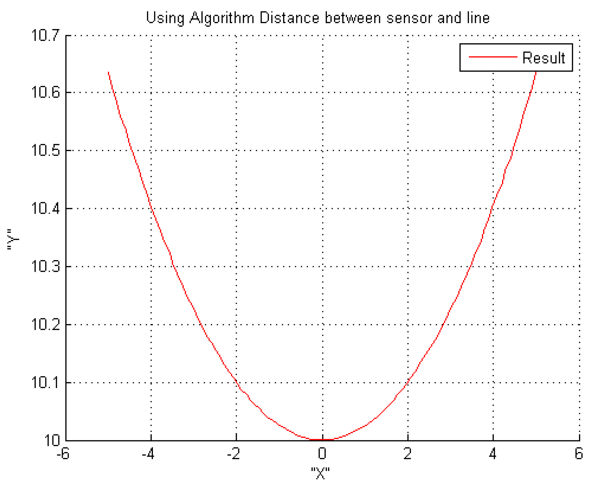
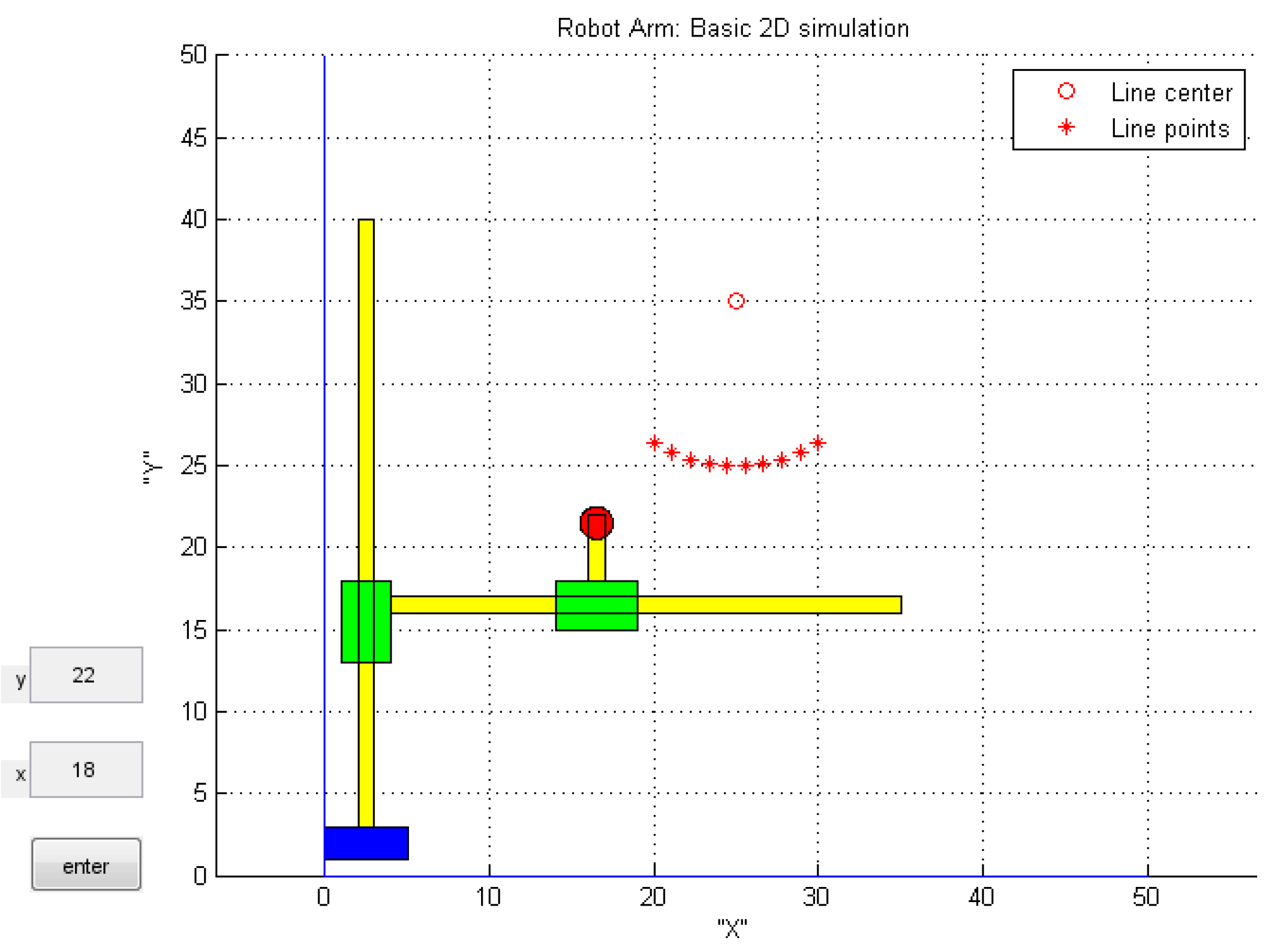
The example graphic of fitting is shown in
Figure 9. In this example, the parabolic function is
, the constants are a = 1.606, b = −1.371, and c = 0.664. However, the circle function is
, the constants are a = 0.427, b = 0.750 and r = 0.377. In proposed tracking algorithm, parabolic curve fitting is used. It is consistent for electric line swing trajectory of our simulation model.
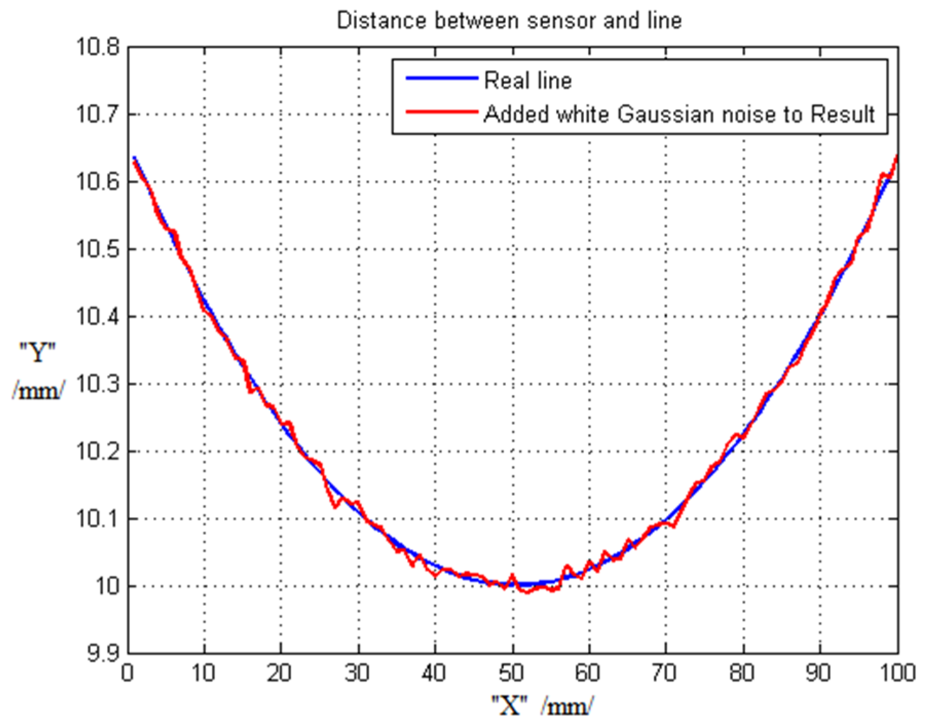
After fitting, the vertical and horizontal actuator of the manipulator should be moved to a center place, and the system waits for the electric line to get to a vertical direction. If the electric line comes on, the current sensor on the manipulator on the mobile robot starts to track the electric line. In this case, the horizontal movement should be controlled by the measurement data of proximity sensors. However, the vertical movement should be controlled by the determined coordinate using the fitted line swing function. The distance between the remote current sensor and the electric line should be held by the minimum permissible constant value. It is possible to determine the vertical coordinate using the horizontal coordinate by the fitted line swing function. Then, the electric line tracking can be executed. After the current measurement, the mobile robot should move to the next target coordinate along the electric line, and repeat the above process.


