
Accurate Attitude Estimation Using ARS under Conditions of Vehicle Movement Based on Disturbance Acceleration Adaptive Estimation and Correction


Abstract
:1. Introduction
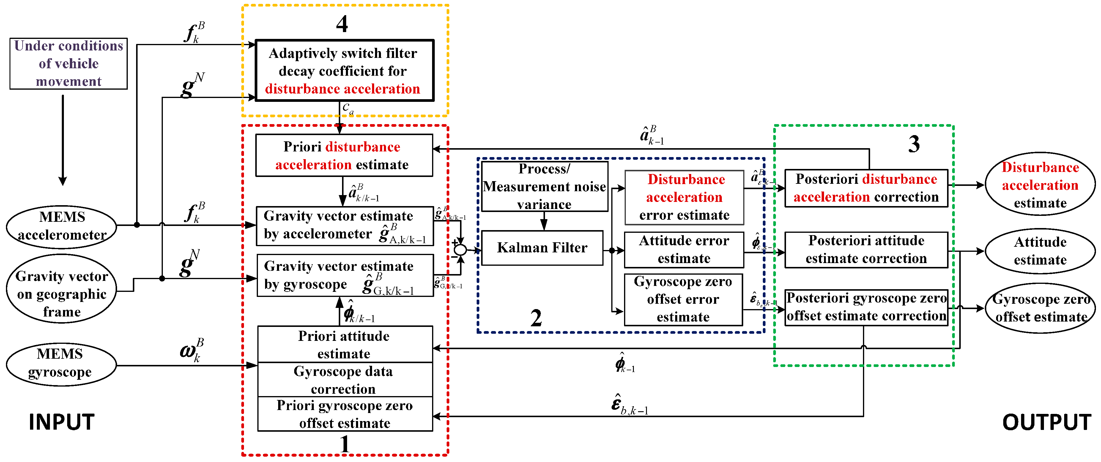
2. Attitude Estimation Based on the Disturbance Acceleration Adaptive Estimate and Correction
- Calculation of the measurement error vector, that is the difference of gravity vector estimated by the gyroscope and accelerometer, respectively;
- Estimation of attitude error, gyroscope zero offset error as well as the disturbance acceleration error;
- Correction the estimate of the disturbance acceleration, the gyroscope zero offset and the attitude;
- Adaptive adjustment of the filter decay coefficient of the disturbance acceleration model.
2.1. Model of the Error Process
2.2. Model of the Measurement Error Process
2.3. State Errors Estimate and Correction Process
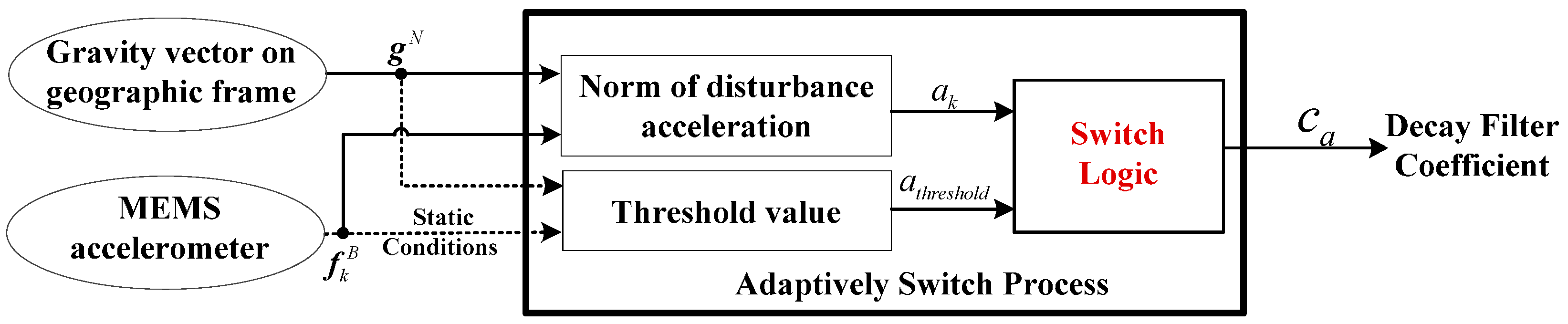
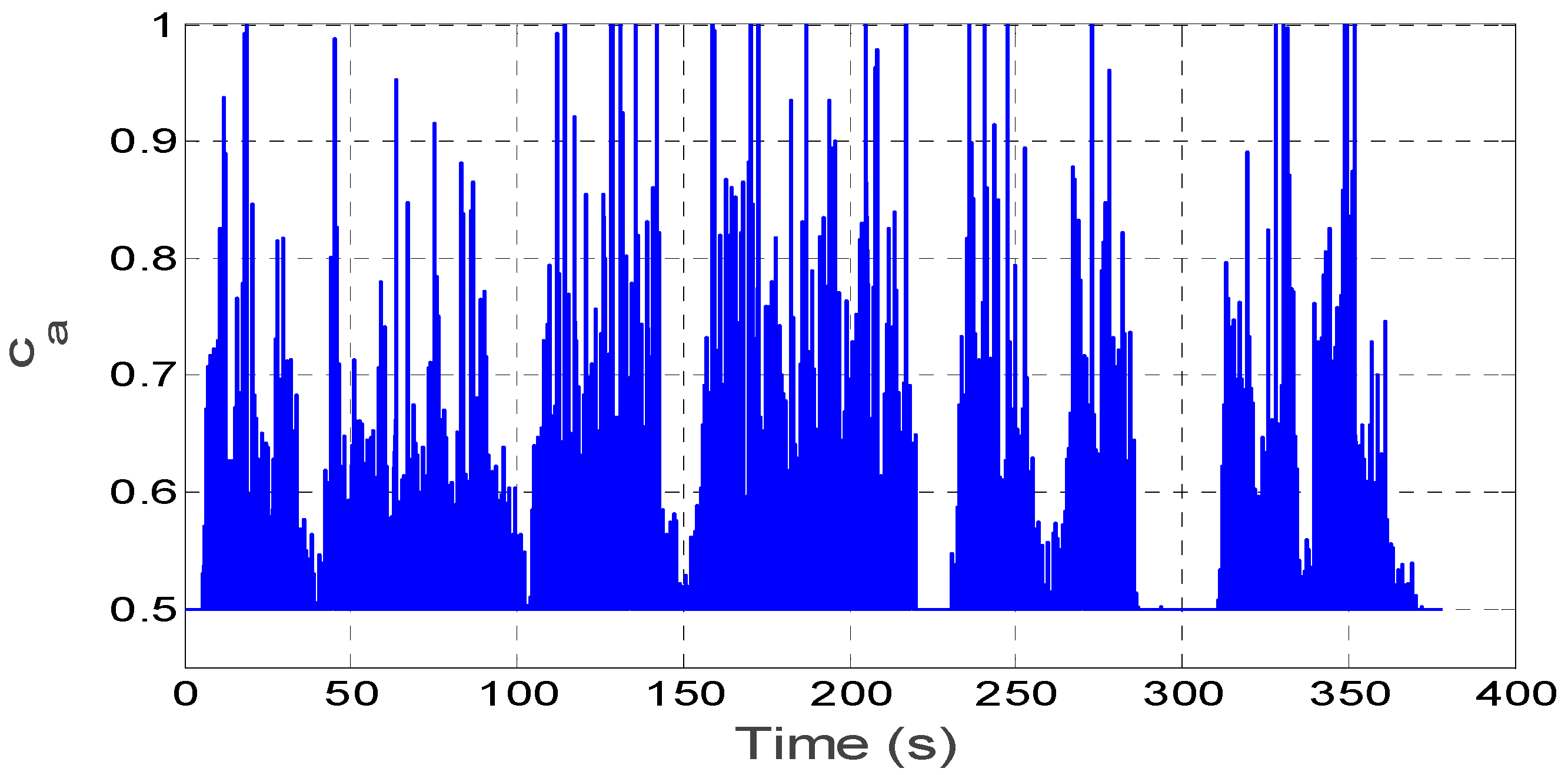
2.4. Adaptive Estimation of Disturbance Acceleration
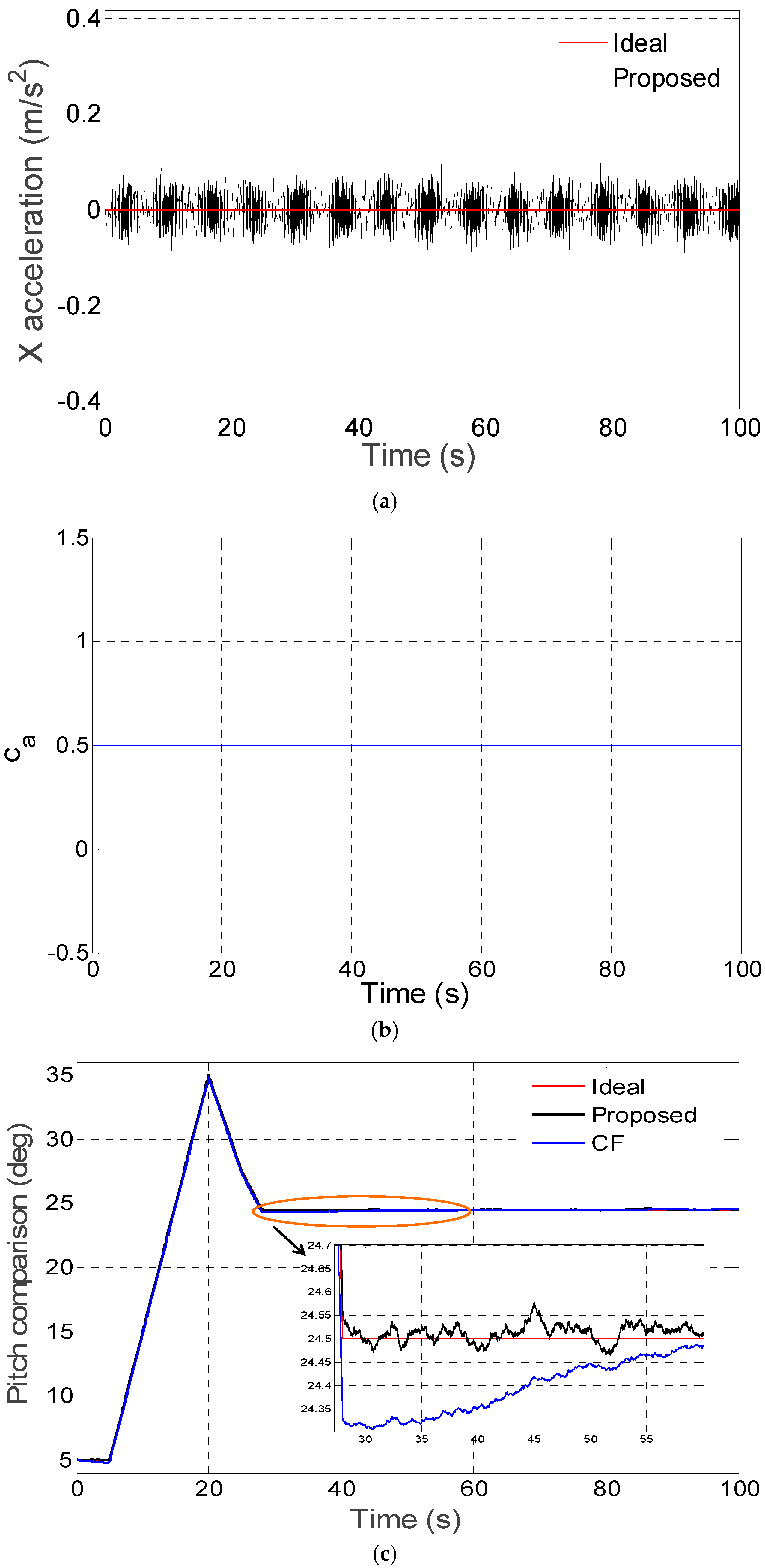
- Non-acceleration mode: In this mode, the paper assumes that ak < 3athreshold. Owing to the little amplitude of the disturbance acceleration, and the acceleration estimate should decay in a short period in the model, namely τ in Equation (20), should be set as a small value. Thus, the filter decay coefficient is set as 0 < ca ≤ 0.5.
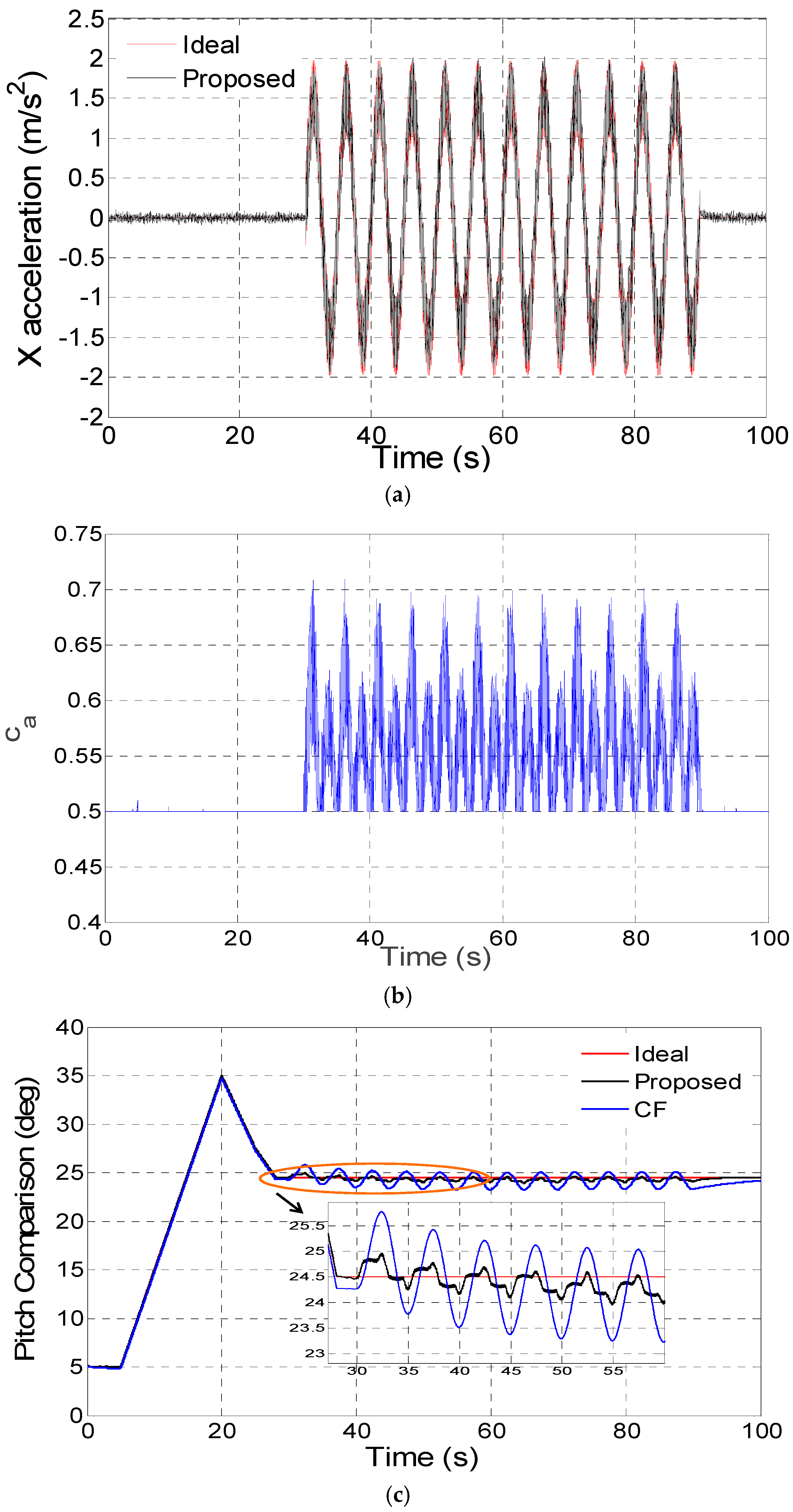
- Vibration-acceleration mode: In this mode, the paper assumes that 3athreshold ≤ ak < 50athreshold. With respect to the changes of the disturbance acceleration, the decay period τ of the acceleration estimate should be set longer than for mode 1. The filter decay coefficient is set as As shown in the formula, ca is adaptively adjusted with respect to ak.
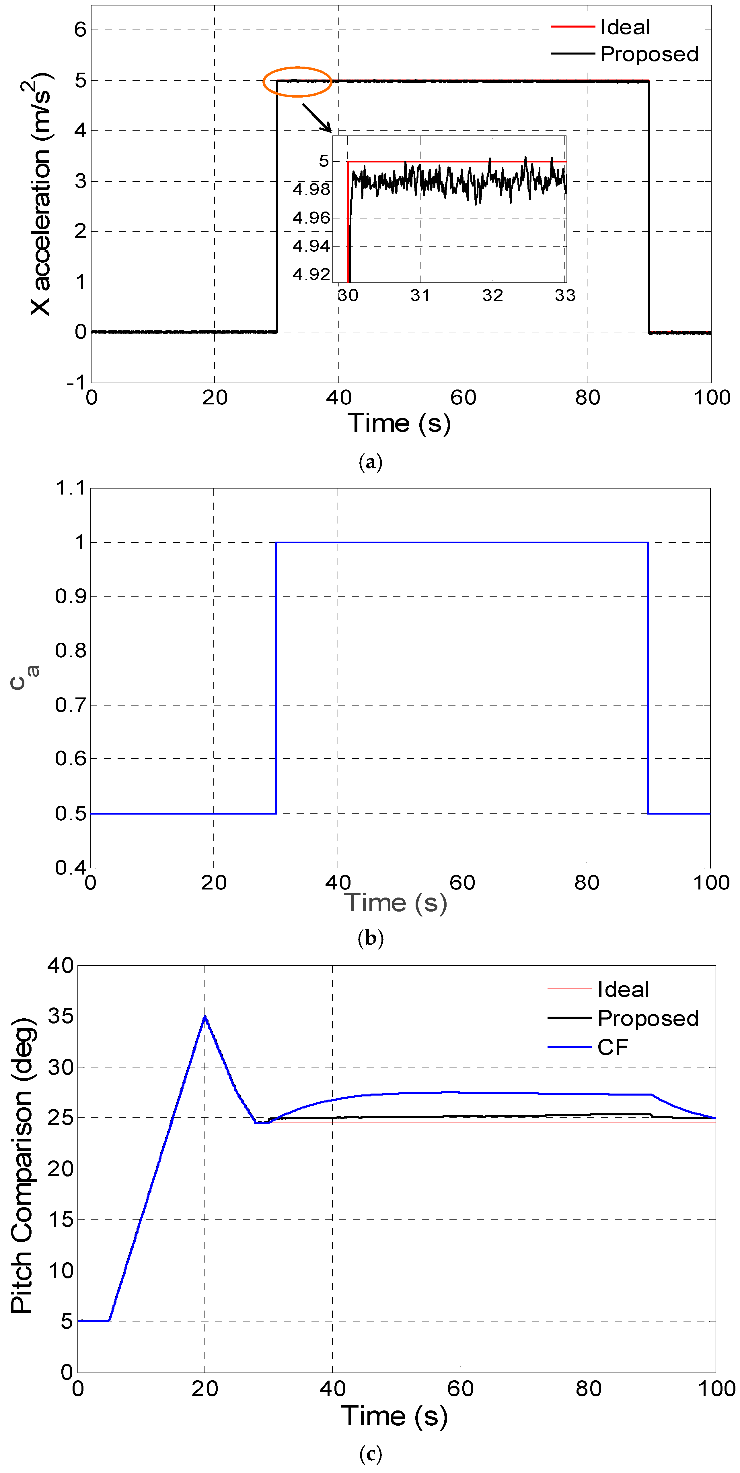
- Sustained-acceleration mode: In this mode, the paper assumes that ak ≥ 50athreshold. As the vehicle is subject to strong and sustained acceleration, the filter decay coefficient ca is set as 1.0.
3. Experiments and Results
3.1. Digital Simulation Experiments and Results
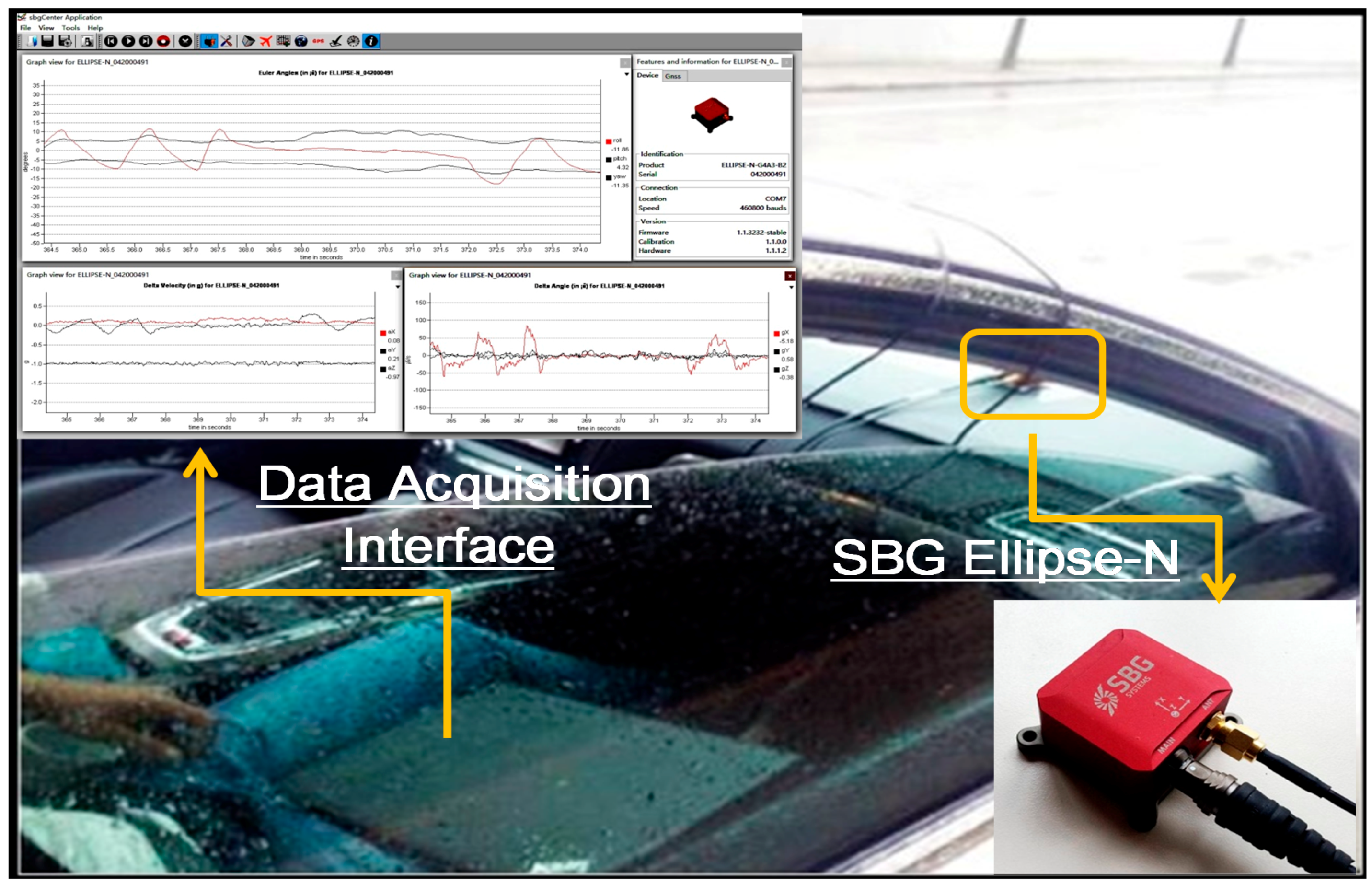
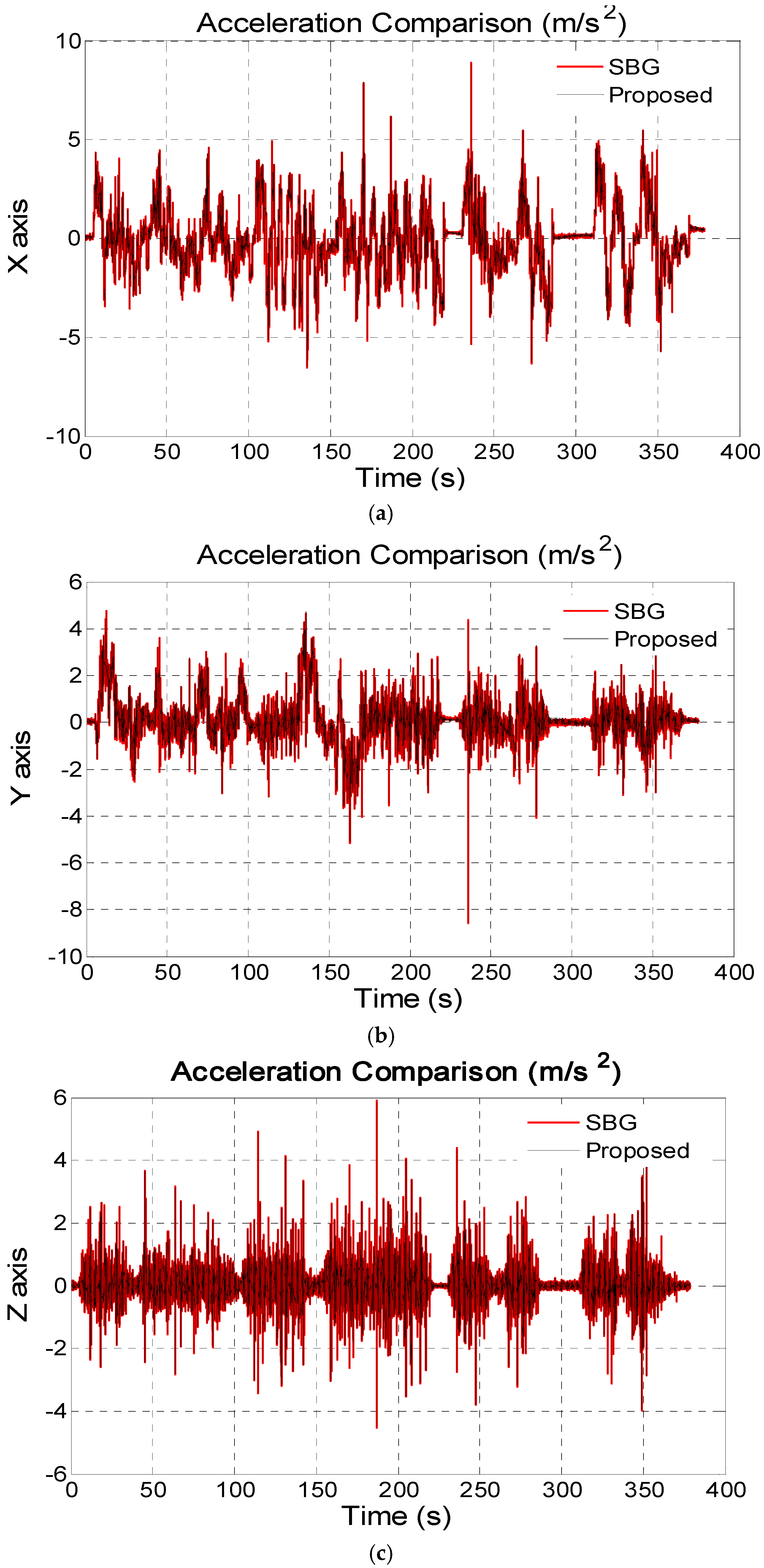
3.2. Kinematic Vehicle Experiments and Results
4. Conclusions
- A disturbance acceleration estimation model based on a first-order Markov process is set up and the disturbance acceleration estimation error is estimated in the Kalman filter.
- In the acceleration estimate model, it analyses the relationship of the filter decay coefficient ca and the correlation time τ of a first-order Markov process, which is the theoretical reason for switching ca.
- The switching logic for ca is designed in accordance with different disturbance acceleration modes.
Acknowledgments
Author Contributions
Conflicts of Interest
References
- Kontoes, C.; Keramitsoglou, I.; Sifakis, N.; Konstantinidis, P. SITHON: An airborne fire detection system compliant with operational tactical requirements. Sensors 2009, 9, 1204–1220. [Google Scholar] [CrossRef] [PubMed]
- Cole, D.; Thompson, P.; Göktogan, A.H.; Sukkarieh, S. System development and demonstration of a cooperative UAV team for mapping and tracking. Int. J. Robot. Res. 2010, 29, 1371–1399. [Google Scholar] [CrossRef]
- Luing, H.; Veltink, P. Measuring orientation of human body segments using gyroscopes and accelerometers. Med. Biol. Eng. Comput. 2005, 43, 273–281. [Google Scholar] [CrossRef]
- Luing, H.; Veltink, P. Inclination measurement of human movement using a 3-D accelerometer with autocalibration. IEEE Trans. Neural Syst. Rehabil. Eng. 2004, 12, 112–121. [Google Scholar] [CrossRef] [PubMed]
- Markley, F.; Mortari, D. Quaternion attitude estimation using vector observations. J. Astronaut. Sci. 2000, 48, 359–380. [Google Scholar]
- Marina, H.G.; Pereda, F.J.; Giron-Sierra, J.M.; Espinosa, F. UAV attitude estimation using unscented Kalman filter and TRIAD. IEEE Trans. Ind. Electron. 2012, 59, 4465–4474. [Google Scholar] [CrossRef]
- Cheng, Y.; Shuster, M. Robustness and Accuracy of the QUEST Algorithm. Adv. Astronaut. Sci. 2007, 127, 41–61. [Google Scholar]
- De Marina, H.G.; Espinosa, F.; Santos, C. Adaptive UAV Attitude Estimation Employing Unscented Kalman Filter, FOAM and Low-Cost MEMS Sensors. Sensors 2012, 12, 9566–9585. [Google Scholar] [CrossRef] [PubMed]
- Guerrero-Castellanos, J.; Madrigal-Sastre, H.; Durand, S.; Torres, L.; Muñoz-Hernández, G.A. A Robust Nonlinear Observer for Real-Time Attitude Estimation Using Low-Cost MEMS Inertial Sensors. Sensors 2013, 13, 15138–15158. [Google Scholar] [CrossRef] [PubMed]
- Li, J.; Cui, H.; Tian, Y. Quaternion constrained filter algorithm for spacecraft attitude determination. J. Harbin Inst. Technol. 2013, 45, 35–40. [Google Scholar]
- Yadav, N.; Bleakley, C. Accurate orientation estimation using AHRS under conditions of magnetic distortion. Sensors 2014, 14, 20008–20024. [Google Scholar] [CrossRef] [PubMed]
- Gao, B.; Zhu, Z.; Zhao, J.; Huang, B. A Wireless Swing Angle Measurement Scheme Using Attitude Heading Reference System Sensing Units Based on Microelectromechanical Devices. Sensors 2014, 14, 22595–22612. [Google Scholar] [CrossRef] [PubMed]
- Valenti, R.; Dryanovski, I.; Xiao, J. Keeping a Good Attitude: A Quaternion-Based Orientation Filter for IMUs and MARGs. Sensors 2015, 15, 19302–19330. [Google Scholar] [CrossRef] [PubMed]
- Yoo, T.; Hong, S.; Yoon, H.; Park, S. Gain-scheduled complementary filter design for a MEMS based attitude and heading reference system. Sensors 2011, 11, 3816–3830. [Google Scholar] [CrossRef] [PubMed]
- Baerveldt, A.J.; Klang, R. A low-cost and low-weight attitude estimation system for an autonomous helicopter. In Proceedings of the IEEE International Conference on Intelligent Engineering Systems, Budapest, Hungary, 15–17 September 1997; pp. 391–395.
- Euston, M.; Coote, P.; Mahony, R.; Kim, J.; Hamel, T. A complementary filter for attitude estimation of a fixed-wing UAV. In Proceedings of the IEEE/RSJ International Conference on Intelligent Robots and Systems, Acropolis Convention Center, Nice, France, 22–26 September 2008; pp. 340–345.
- Bergamini, E.; Ligorio, G.; Summa, A.; Vannozzi, G.; Cappozzo, A.; Sabatini, A.M. Estimating Orientation Using Magnetic and Inertial Sensors and Different Sensor Fusion Approaches: Accuracy Assessment in Manual and Locomotion Tasks. Sensors 2014, 14, 18625–18649. [Google Scholar] [CrossRef] [PubMed]
- Hong, S. Fuzzy logic based closed-loop strapdown attitude system for unmanned aerial vehicle (UAV). Sens. Actuators A 2003, 107, 109–118. [Google Scholar] [CrossRef]
- Roetenberg, D.; Luing, H.J.; Baten, C.T.; Veltink, P.H. Compensation of magnetic disturbances improves inertial and magnetic sensing of human body segment orientation. IEEE Trans. Neural Syst. Rehabil. Eng. 2005, 13, 395–405. [Google Scholar] [CrossRef] [PubMed]
- Peng, H.; Zhi, X.; Wang, R.; Liu, J.; Zhang, C. A new dynamic calibration method for IMU deterministic errors of the INS on the Hypersonic Crusie Vechicles. Aerosp. Sci. Technol. 2014, 32, 121–130. [Google Scholar] [CrossRef]
- Harms, H.; Amft, O.; Winkler, R.; Tröster, G. ETHOS: Miniature Orientation Sensor for Wearable Human Motion Analysis. Sensors 2010, 143, 1037–1042. [Google Scholar]
- Grip, H.F.; Fossen, T.; Johansen, T.A. Attitude estimation using biased gyro and vector measurements with time-varying reference vectors. IEEE Trans. Autom. Control 2012, 57, 1332–1338. [Google Scholar] [CrossRef]
- Gebre-Egziabher, D.; Hayward, R.; Powell, J. Design of Multi-sensor Attitude Determination Systems. IEEE Trans. Aerosp. Electron. Syst. 2004, 40, 627–649. [Google Scholar] [CrossRef]
- Munguia, R.; Grau, A. An attitude and heading reference system (AHRS) based in a dual filter. In Proceedings of the 16th Conference on Emerging Technologies & Factory Automation (ETFA), Toulouse, France, 5–9 September 2011; pp. 1–8.
- Ko, N.Y.; Jeong, S.; Bae, Y. Sine Rotation Vector Method for Attitude Estimation of an Underwater Robot. Sensors 2016, 16, 1213. [Google Scholar] [CrossRef] [PubMed]
- Rui, H.U.; Xue, X.Z.; Zhao, S.F.; Yang, Y.C. Vehicle attitude estimation method based on fault detection and fuzzy logic. J. Chin. Inert. Technol. 2008, 16, 405–409. [Google Scholar]
- Luing, H. Inertial Sensing of Human Movement. Ph.D. Thesis, Twente University, Enschede, The Netherlands, 2002. [Google Scholar]


| Error Parameters | Gyroscope | Accelerometer | |
|---|---|---|---|
| First-order Gauss-Markov Process | Correlation Time | 100 s | - |
| White Noise | 10 °/h | - | |
| White Noise | 0.1 °/s | 5 mg | |
| Pitch Error (°) | Non-Acceleration | Vibration-Acceleration | Sustained-Acceleration | |||
|---|---|---|---|---|---|---|
| Proposed | CF | Proposed | CF | Proposed | CF | |
| MAX | 1.65 × 10⁻² | 5.95 × 10⁻² | 4.63 × 10⁻¹ | 1.28 | 8.44 × 10⁻¹ | 2.98 |
| RMS | 3.18 × 10⁻² | 1.26 × 10⁻¹ | 1.95 × 10⁻¹ | 6.12 × 10⁻¹ | 5.32 × 10⁻¹ | 2.12 |
| Performance Index | Gyroscope | Acceleration |
|---|---|---|
| Bias Instability | 8 °/h | 10 mg |
| Angle Random Walk | - | |
| Speed Random Walk | - |
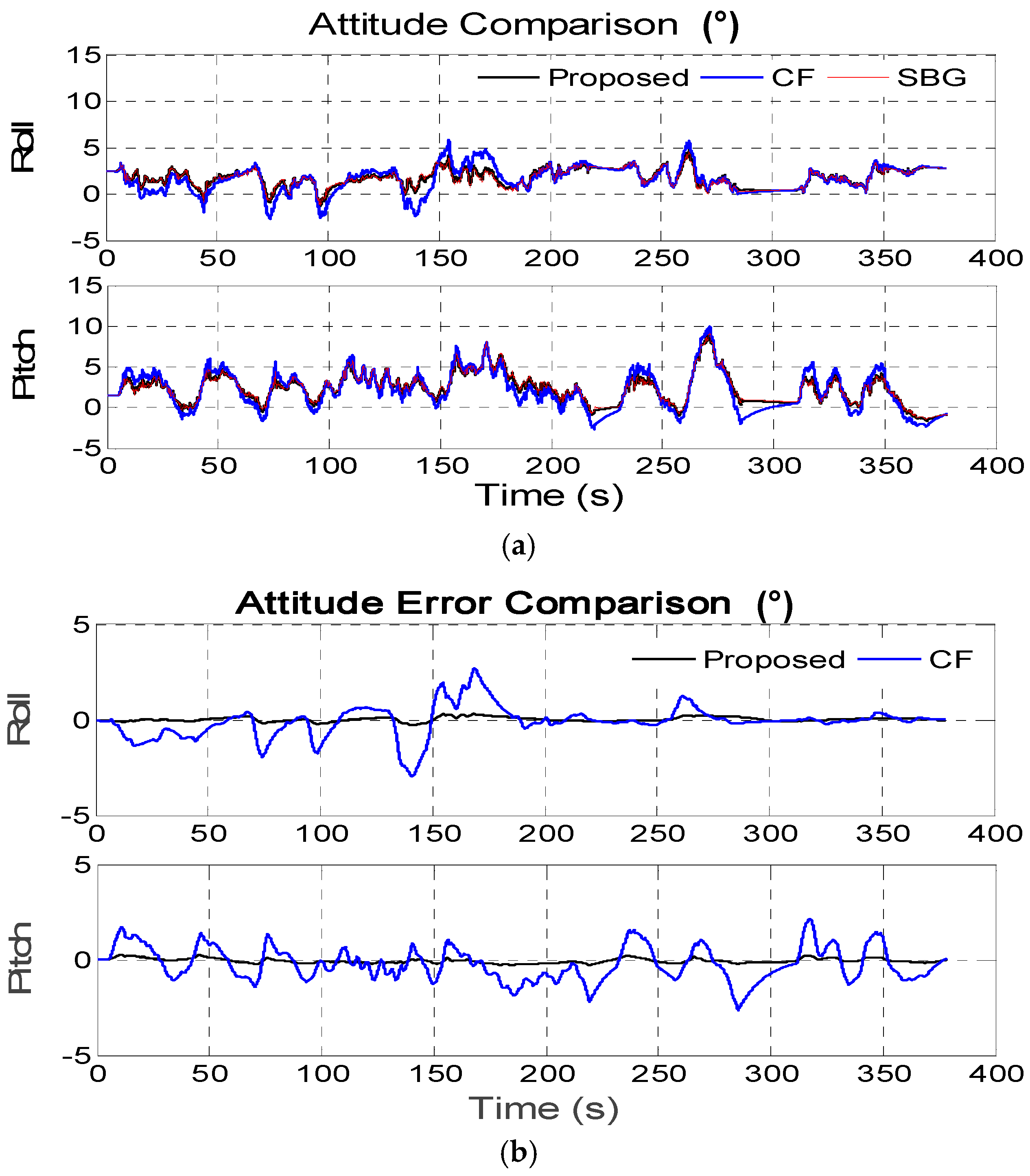
| Roll Error (°) | Pitch Error (°) | |||
|---|---|---|---|---|
| Proposed | CF | Proposed | CF | |
| MAX | 3.24 × 10⁻¹ | 2.96 | 2.89 × 10⁻¹ | 2.65 |
| RMS | 1.14 × 10⁻¹ | 8.09 × 10⁻¹ | 1.31 × 10⁻¹ | 9.12 × 10⁻¹ |
© 2016 by the authors; licensee MDPI, Basel, Switzerland. This article is an open access article distributed under the terms and conditions of the Creative Commons Attribution (CC-BY) license (http://creativecommons.org/licenses/by/4.0/).
Share and Cite
Xing, L.; Hang, Y.; Xiong, Z.; Liu, J.; Wan, Z. Accurate Attitude Estimation Using ARS under Conditions of Vehicle Movement Based on Disturbance Acceleration Adaptive Estimation and Correction. Sensors 2016, 16, 1716. https://doi.org/10.3390/s16101716
Xing L, Hang Y, Xiong Z, Liu J, Wan Z. Accurate Attitude Estimation Using ARS under Conditions of Vehicle Movement Based on Disturbance Acceleration Adaptive Estimation and Correction. Sensors. 2016; 16(10):1716. https://doi.org/10.3390/s16101716
Chicago/Turabian StyleXing, Li, Yijun Hang, Zhi Xiong, Jianye Liu, and Zhong Wan. 2016. "Accurate Attitude Estimation Using ARS under Conditions of Vehicle Movement Based on Disturbance Acceleration Adaptive Estimation and Correction" Sensors 16, no. 10: 1716. https://doi.org/10.3390/s16101716