
Towards a Low-Cost Remote Memory Attestation for the Smart Grid

 ,
, 
Abstract
:1. Introduction
2. Network Model and Threat Model
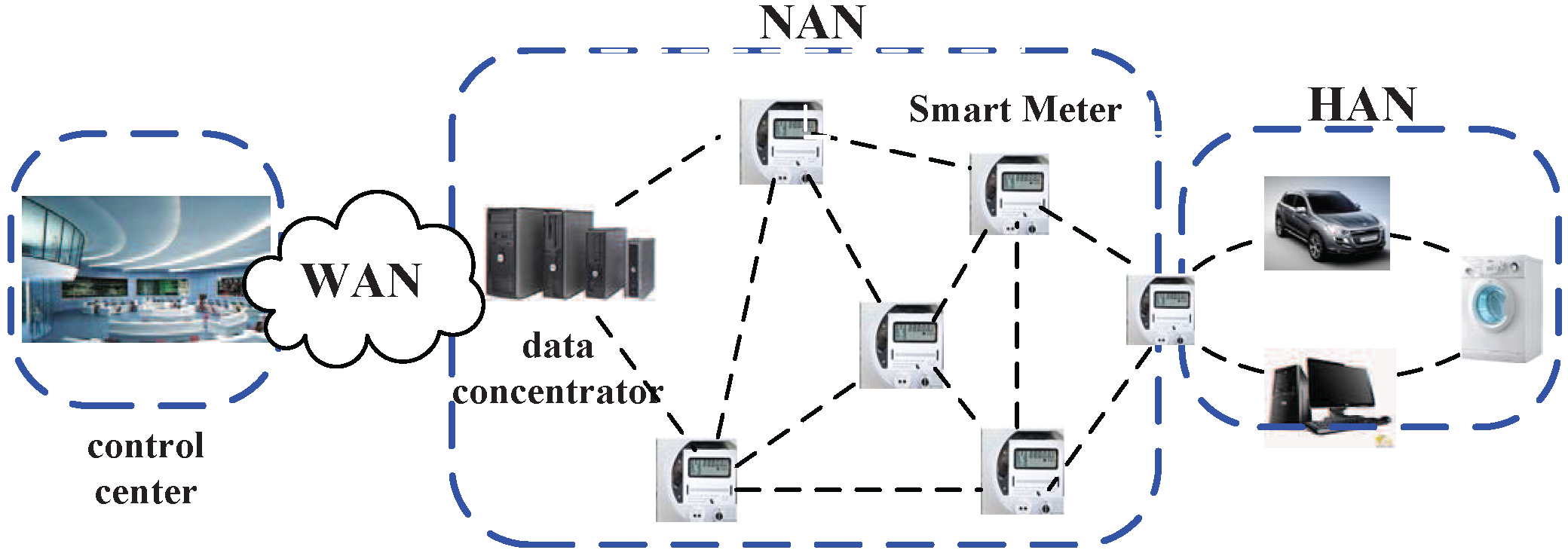
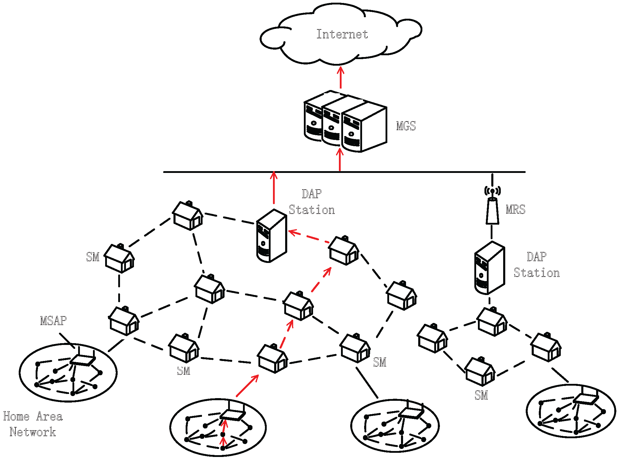
2.1. Network Model
2.2. Threat Model
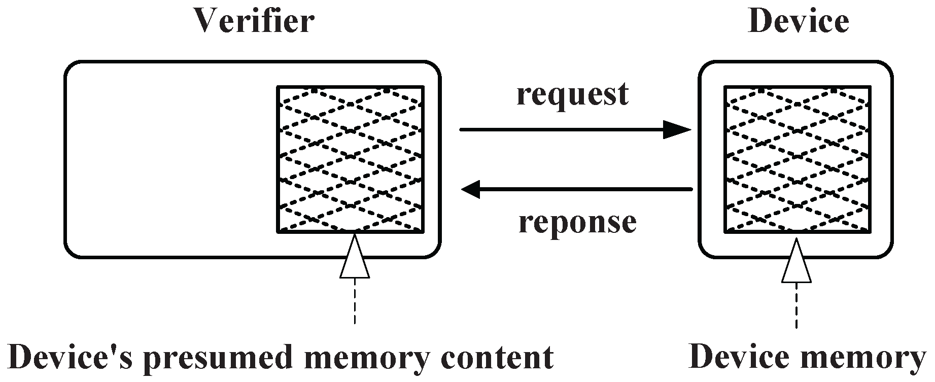
3. Our Approach
3.1. Design Rationale


| The value of node i | |
| The probability of node i being compromised in an attack | |
| λ | The number of attacks in a unit of time |
| The number of periods to compute the risk value | |
| The risk value of node i | |
| p | The current period |
| The number of attestation failure of node i in period p | |
| N | The total number of nodes in the network |
| n | The number of hops in a path |
| T | The unit of time |
| The single verification time | |
| β | The scaling factor for an attestation interval |
| The number of verification in a time duration T | |
| The maximum end-to-end delay in the network | |
| The average one-hop delay in the network |
3.2. Dynamic Attestation Based on the Node’s Risk Level
- Step 1: initialization: Before the network is deployed, the verifier will initialize the risk value on each node. The risk value on each node is set to zero before the first attestation (i.e., the node has not been compromised). Therefore, we have:where means the risk value of node i.
- Step 2: attestation interval generation: The verifier validates nodes with different attestation rates, which are determined by the risk values of the nodes. It is worth noting that the attestation rate is proportional to the security risk of nodes. Therefore, nodes with a high risk value will be verified more frequently by using a higher rate. Then, the p-th attestation interval on node i can be represented as follows:where T is the unit time, N is the number of nodes in the network, is the risk value of node i at the p-th attestation interval, is the average risk value of all nodes at the p-th attestation interval, β is the scaling factor for the attestation interval and φ is a constant that controls the updated step or convergence speed of the attestation interval .Then, the attestation time is selected randomly in the p-th interval by,where is the random time in period and is the p-th attestation interval on node i.
- Step 3: update: After each attestation process, the verifier will update the risk value of the node based on the attestation result. If the attestation fails, the counter of attestation failures will increase by one, as well as the risk value . After a time slot, the risk value will be updated, as well. The risk value will be updated based on summarizing the counters of attestation failures in recent slots.
| Algorithm 1 The verifier process (Part I). | |
| 1: | procedure ChallengeGeneration(, φ, β) |
| 2: | for all do |
| 3: | Generate attestation interval |
| 4: | Generate attestation time |
| 5: | |
| 6: | Attached with seed |
| 7: | Send challenge message |
| 8: | Record sent time |
| 9: | end for |
| 10: | end procedure |
| Algorithm 2 The verifier process (Part II). | |
| 11: | procedure ChecksumVerification(, , ) |
| 12: | Record received time |
| 13: | if then |
| 14: | Generate another checksum |
| 15: | if then |
| 16: | |
| 17: | Delay on each hop |
| 18: | Get average delay |
| 19: | |
| 20: | Bayesian classifier decision |
| 21: | else |
| 22: | Checksum Inconsistency Error MAC Inconsistency Error |
| 23: | end if |
| 24: | else |
| 25: | MAC Inconsistency Error |
| 26: | end if |
| 27: | end procedure |
| Algorithm 3 The relay node process. | |
| 1: | procedure RelayNodeForwarding(ReceivedPacket) |
| 2: | if ReceivedPacket = request then |
| 3: | Forward packet |
| 4: | Record forwarding time |
| 5: | else |
| 6: | Record forwarding time |
| 7: | Forward packet |
| 8: | Get time difference |
| 9: | Generate report message |
| 10: | end if |
| 11: | end procedure |
| Algorithm 4 The remote device checksum generation process. | |
| 1: | procedure RemoteDeviceChecksum(, W) |
| 2: | Set |
| 3: | while do |
| 4: | |
| 5: | |
| 6: | |
| 7: | |
| 8: | end while |
| 9: | Generate checksum |
| 10: | Generate and send response message |
| 11: | end procedure |
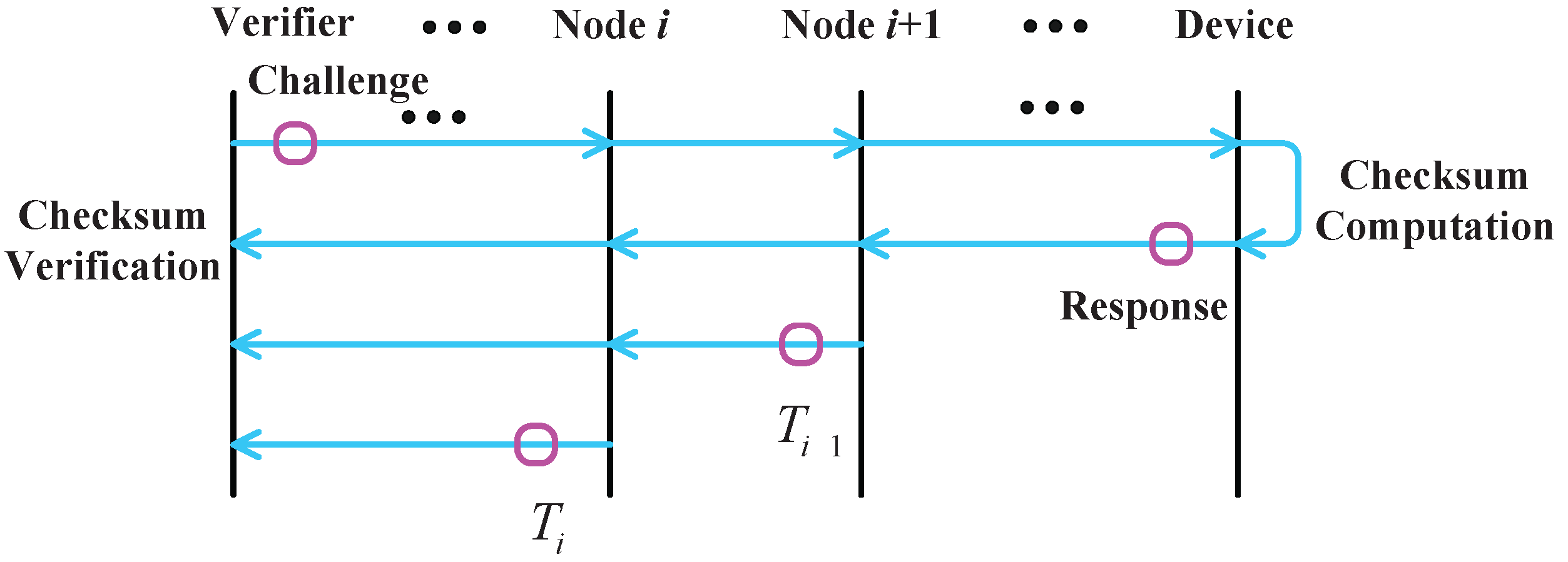
3.3. Delay-Resilient Remote Memory Attestation
- Step 1: challenge generation: The verifier sends a random challenge message to the remote device;
- Step 2: challenge transmission: The relay node forwards the challenge message to the destination node and records the time when the challenge message is received by them;
- Step 3: checksum generation: The remote device computes the checksum according to the challenge issued by the verifier and returns the response to the verifier;
- Step 4: checksum transmission: The relay node forwards the checksum from the remote device to the verifier, records the time when the response message is received by the relay nodes and then reports the time difference between the challenge and the response to the verifier;
- Step 5: checksum verification: The verifier separately computes the corresponding checksum and verifies the correctness of the checksum returned by the remote device. If checksums are the same, the verifier will continue to verify the time for computing;
- Step 6: determination: The verifier computes the network delay using the time differences reported by relay nodes and compares the response time with the normal one. In this way, the remote device can determine whether it is compromised or not. DRMA obtains the computing time of the remote device with the consideration of the network delay, in order to achieve greater accuracy for the detection.
3.3.1. Step 1: Challenge Generation
- Step 1.1: The verifier generates a random key based on the current time of the verifier, which is shown as follows:where is the current time of the verifier.
- Step 1.2: The message is generated and transmitted:where is the seed for the function.
- Step 1.3: The verifier sends a challenge message to the remote device with the corresponding message authentication code as:where m is the message sent by the verifier.The verifier records the message when the packet is sent as:where is the current time of the verifier.
3.3.2. Step 2: Challenge Transmission
- Step 2.1: The relay node forwards the challenge to the next hop.where is the challenge forwarded by the relay node i.
- Step 2.2: The relay node records the time when the request is forwarded.where is the current time of node i.
3.3.3. Step 3: Checksum Generation
- Step 3.1: The remote device obtains the key from the verifier and initiates the to generate the random memory addresses as follows:where is the random key generated by the verifier and is the seed for function.
- Step 3.2: The remote device obtains the memory contents of the addresses to compute the checksum:where is the address of the memory that is accessed and is the j-th checksum.
- Step 3.3: The remote device generates the checksum and returns it to the verifier with the corresponding :where is the j-th checksum.
3.3.4. Step 4: Checksum Transmission
- Step 4.1: The relay node records the time when the response is received.where is the current time of relay node i.
- Step 4.2: The relay forwards the response to the next hop.where is the checksum forwarded by the relay node i.
- Step 4.3: The relay node computes the time difference between the request and the response.where is the time when the node i forwarded the challenge request.
- Step 4.4: The relay node reports the time difference to the verifier after a while.where is the time difference between the challenge and the response forwarding.
3.3.5. Step 5: Checksum Verification
- Step 5.1: The verifier records when the response is received.where is the current time of the verifier.
- Step 5.2: The verifier computes the separately and compares it to the in the response message.where is the MAC of the checksum on the remote device.
- Step 5.3: If the are the same, the verifier computes checksum separately and records the computing time .where is the k-th checksum computed by the verifier.
- Step 5.4: The verifier compares the checksum with the C in the response.where C is the checksum generated by the remote device.
3.3.6. Step 6: Determination
- Step 6.1: If checksums are the same, the verifier will compute the time spent in the entire challenge response.where is the time when the verifier receives the response and is the time when the verifier sends the challenge request.
- Step 6.2: The verifier receives the reports from the relay nodes and computes the delay on each hop on the path.where is the time difference reported by relay node i.
- Step 6.3: After eliminating the exceptional data by the Pauta criterion [28], the average delay in the network can be estimated by the sample mean:where is the number of samples after eliminating the exceptional data and is the sample mean.
- Step 6.4: According to the derived transmission delay, the verifier obtains the time spent on computing the checksum as follows:where is the time difference between the challenge sent and the response received by the verifier.
- Step 6.5: The verifier computes the posterior probability and the conditional risk based on the minimum risk Bayesian classifier [28].where the observation x is the difference between the received checksum computing time and the verifier’s computing time . The a priori probability is the probability of the node being compromised, which can be determined by the compromised history of the network. The class conditional probability density can be estimated by the response time distribution of both the compromised nodes and the normal nodes with the experiment. The decision function is determined by the damage caused by the wrong decisions according to the importance of the nodes.
- Step 6.6: Comparing the conditional risk , the verifier will find the decision that minimizes the conditional risk, as follows:where c is the minimum risk Bayes decision, x is the observation and the is the corresponding decision. Then, the verifier can confirm whether the remote node is compromised according to c.
4. Analysis
4.1. Efficiency Analysis
4.1.1. The Number of Detected Attacks
4.1.2. Verification Time
4.2. Security Analysis
4.2.1. Local Forged Checksum
4.2.2. Relay Nodes False Reports on the Time Difference
4.2.3. Relay Nodes’ Deferred Forwarding
4.2.4. Relay Nodes Collusion
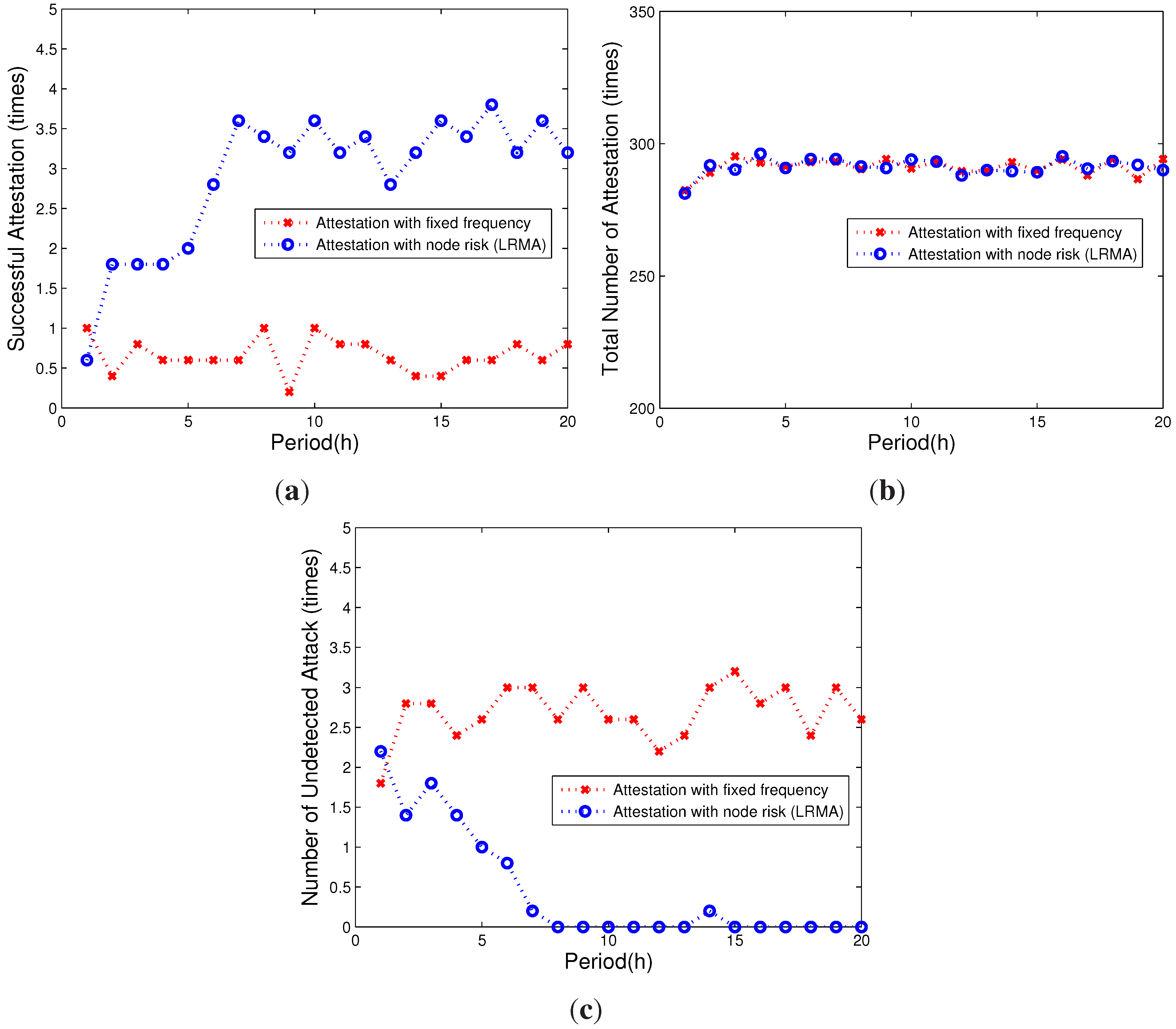
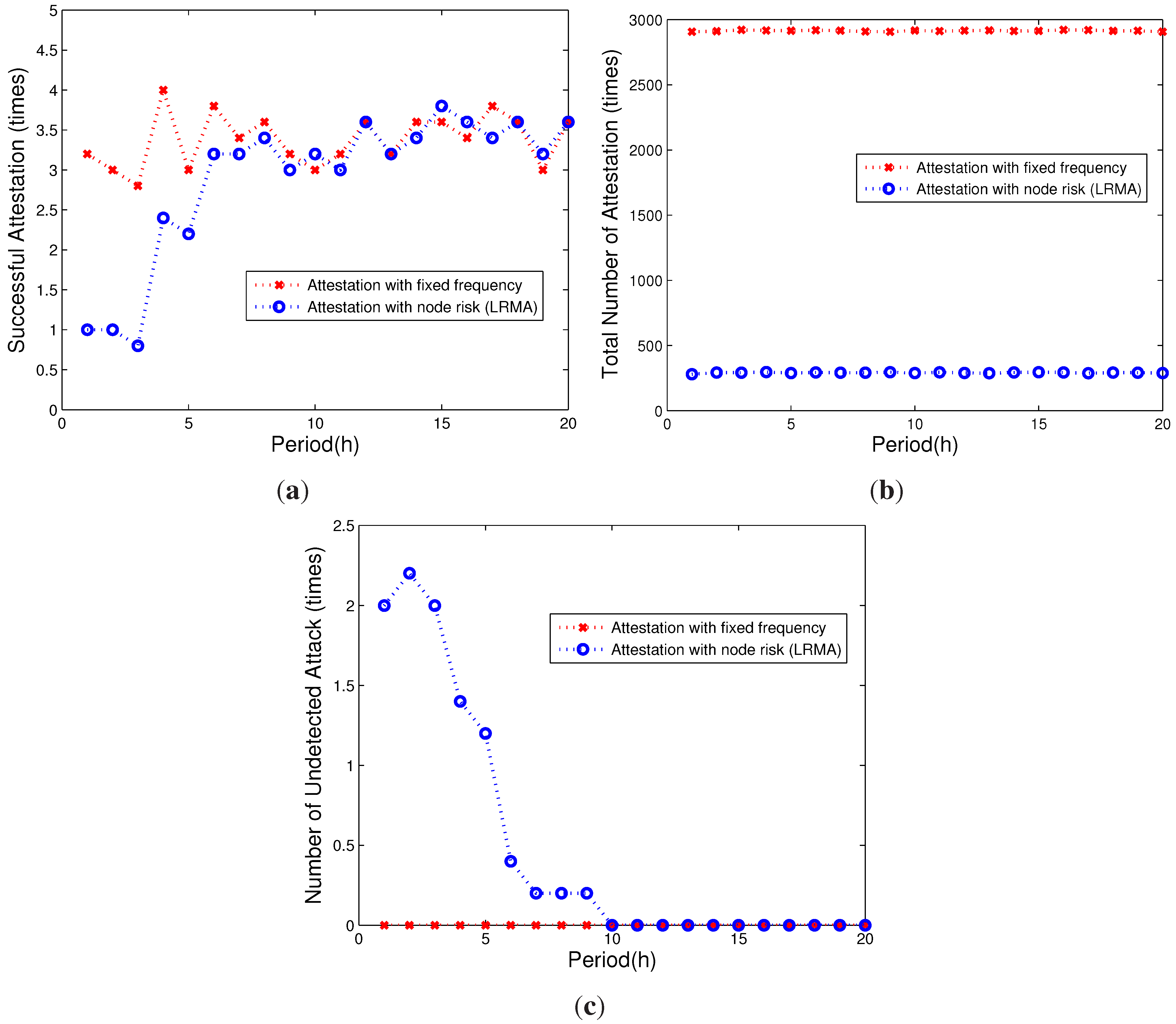
5. Performance Evaluation
5.1. Methodology
5.2. Results
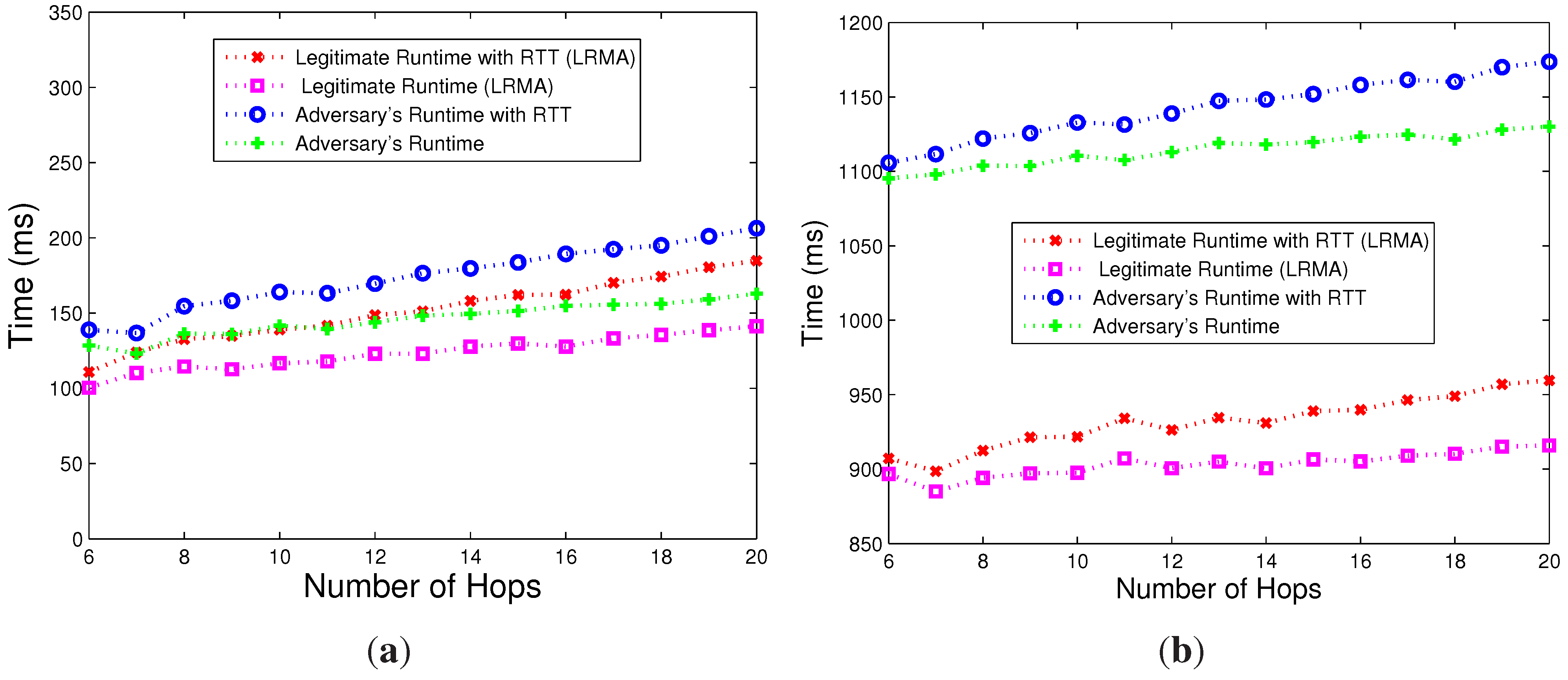
5.2.1. Attestation Efficiency
5.2.2. Attestation Overhead
5.2.3. Overhead of Computing the Checksum

6. Discussion
- Attack interval: In this paper, we assume that all attacks are independent and that the attack interval has an exponential distribution with a rate parameter λ. In a realistic environment, there may be more than one adversary in the network, and the attack interval may not be in a regular pattern. The performance in this case shall be analyzed further, and the proposed scheme shall be enhanced to address this issue.
- Hybrid network: In this paper, we consider that the network is uniform and that all of the nodes in the network are the same. Nonetheless, the realistic AMI may be a hybrid network. As such, the network delay of remote nodes in different locations may not be alike, as well as the computation time of the checksum. Then, the verifier must have a proper mechanism to distinguish them and confirm compromised nodes in the network. Therefore, how to deal with the hybrid network is another issue for future study.
- Extensibility: In addition to the smart grid, there are numerous systems where the legacy system exists. Our proposed scheme is generic and can be extended to systems where the remote memory attestation is needed, but the hardware or computing capability is limited. As shown in our analytical and evaluation results, our proposed scheme can achieve a great performance with a lower overhead.
7. Related Work
8. Conclusions
Acknowledgments
Author Contributions
Conflicts of Interest
References
- Zhang, Z.; Lu, Z.; Chen, Q.; Yan, X.; Zheng, L.R. Code division multiple access/pulse position modulation ultra-wideband radio frequency identification for Internet of Things: Concept and analysis. Int. J. Commun. Syst. 2012, 25, 1103–1121. [Google Scholar] [CrossRef]
- Ning, H.; Hu, S. Technology classification, industry, and education for Future Internet of Things. Int. J. Commun. Syst. 2012, 25, 1230–1241. [Google Scholar] [CrossRef]
- Liu, Y.; Chen, Z.; Xia, F.; Lv, X.; Bu, F. An integrated scheme based on service classification in pervasive mobile services. Int. J. Commun. Syst. 2012, 25, 1178–1188. [Google Scholar] [CrossRef]
- Li, F.; Qiao, W.; Sun, H.; Wan, H.; Wang, J.; Xia, Y.; Xu, Z.; Zhang, P. Smart transmission grid: Vision and framework. IEEE Trans. Smart Grid 2010, 1, 168–177. [Google Scholar] [CrossRef]
- DeBlasio, R.; Tom, C. Standards for the smart grid. In Proceedings of the Energy 2030 Conference (ENERGY 2008), Atlanta, GA, USA, 17–18 November 2008.
- Huang, Y.; Esmalifalak, M.; Nguyen, H.; Zheng, R.; Han, Z.; Li, H.; Song, L. Bad data injection in smart grid: Attack and defense mechanisms. IEEE Commun. Mag. 2013, 51, 27–33. [Google Scholar] [CrossRef]
- Yang, X.; Lin, J.; Moulema, P.; Yu, W.; Fu, X.; Zhao, W. A Novel En-Route Filtering Scheme against False Data Injection Attacks in Cyber-Physical Networked Systems. In Proceedings of the IEEE 32nd International Conference on Distributed Computing Systems(ICDCS), Macau, China, 18–21 June 2012; pp. 92–101.
- Xie, L.; Mo, Y.; Sinopoli, B. Integrity Data Attacks in Power Market Operations. IEEE Trans. Smart Grid 2011, 2, 659–666. [Google Scholar] [CrossRef]
- Seshadri, A.; Luk, M.; Perrig, A.; van Doorn, L.; Khosla, P. SCUBA: Secure code update by attestation in sensor networks. In Proceedings of the 5th ACM Workshop on Wireless Security, Los Angeles, CA, USA, 29 September 2006; pp. 85–94.
- Song, K.; Seo, D.; Park, H.; Lee, H.; Perrig, A. OMAP: One-way memory attestation protocol for smart meters. In Proceedings of the Ninth IEEE International Symposium on Parallel and Distributed Processing with Applications Workshops (ISPAW), Busan, Korea, 26–28 May 2011; pp. 111–118.
- Seshadri, A.; Perrig, A.; van Doorn, L.; Khosla, P. Swatt: Software-based attestation for embedded devices. In Proceedings of the IEEE Symposium on Security and Privacy, Oakland, CA, USA, 9–12 May 2004; pp. 272–282.
- Akram, R.N.; Markantonakis, K.; Mayes, K. A Secure and Trusted Channel Protocol for the User Centric Smart Card Ownership Model. In Proceedings of the 12th IEEE International Conference on Trust, Security and Privacy in Computing and Communications (TrustCom), Melbourne, VIC, Australia, 16–18 July 2013; pp. 336–345.
- Armknecht, F.; Sadeghi, A.R.; Schulz, S.; Wachsmann, C. A security framework for the analysis and design of software attestation. In Proceedings of the 2013 ACM SIGSAC conference on Computer & Communications Security, Berlin, Germany, 4–8 November 2013; pp. 1–12.
- Yang, Y.; Wang, X.; Zhu, S.; Cao, G. Distributed software-based attestation for node compromise detection in sensor networks. In Proceedings of the 26th IEEE International Symposium on Reliable Distributed Systems (SRDS), Beijing, China, 10–12 October 2007; pp. 219–230.
- Shaneck, M.; Mahadevan, K.; Kher, V.; Kim, Y. Remote software-based attestation for wireless sensors. In Security and Privacy in Ad-Hoc and Sensor Networks; Springer: Visegrad, Hungary, 13–14 July 2005; pp. 27–41. [Google Scholar]
- Srinivasan, R.; Dasgupta, P.; Gohad, T.; Bhattacharya, A. Determining the integrity of application binaries on unsecure legacy machines using software based remote attestation. In Proceedings of 6th International Conference on Information Systems Security (ICISS 2010), Gandhinagar, India, 17–19 December 2010; pp. 66–80.
- Jakobsson, M.; Johansson, K.A. Practical and secure software-based attestation. In Proceedings of the IEEE Workshop on Lightweight Security & Privacy: Devices, Protocols and Applications (LightSec), Istanbul, Turkey, 14–15 March 2011; pp. 1–9.
- Castelluccia, C.; Francillon, A.; Perito, D.; Soriente, C. On the difficulty of software-based attestation of embedded devices. In Proceedings of the 16th ACM Conference on Computer and Communications Security, Chicago, IL, USA, 9–13 November 2009; pp. 400–409.
- Lu, Z.; Lu, X.; Wang, W.; Wang, C. Review and evaluation of security threats on the communication networks in the smart grid. In Proceedings of the IEEE Military Communications Conference (MILCOM), San Jose, CA, USA, 31 October–3 November 2010; pp. 1830–1835.
- Malekzadeh, M.; Ghani, A.A.A.; Subramaniam, S. A new security model to prevent denial-of-service attacks and violation of availability in wireless networks. Int. J. Commun. Syst. 2012, 25, 903–925. [Google Scholar] [CrossRef]
- Bysani, L.; Turuk, A. A Survey on Selective Forwarding Attack in Wireless Sensor Networks. In Proceedings of the IEEE International Conference on Devices and Communications (ICDeCom), Mesra, Ranchi, India, 24–25 February 2011; pp. 1–5.
- Moamen, A.A.; Hamza, H.S.; Saroit, I.A. Secure multicast routing protocols in mobile ad-hoc networks. Int. J. Commun. Syst. 2014, 27, 2808–2831. [Google Scholar] [CrossRef]
- Gharavi, H.; Hu, B. Multigate communication network for smart grid. IEEE Proc. 2011, 99, 1028–1045. [Google Scholar] [CrossRef]
- Liu, Y.; Reiter, M.K.; Ning, P. False Data Injection Attacks against State Estimation in Electric Power Grids. In Proceedings of the 16th ACM Conference on Computer and Communications Security (CCS), Chicago, IL, USA, 9–13 November 2009; pp. 21–32.
- Yang, X.; Lin, J.; Moulema, P.; Yu, W.; Fu, X.; Zhao, W. (Eds.) A Novel En-Route Filtering Scheme against False Data Injection Attacks in Cyber-Physical Networked Systems. IEEE Trans. Comput. 2015, 64, 4–18.
- Lin, J.; Yu, W.; Yang, X.; Xu, G.; Zhao, W. On False Data Injection Attacks against Distributed Energy Routing in Smart Grid. In Proceedings of the 2012 IEEE/ACM Third International Conference on Cyber-Physical Systems (ICCPS), Beijing, China, 17–19 April 2012.
- He, X.; Yang, X.; Li, R.; Yang, Q. A Novel Delay-resilient Remote Memory Attestation for Smart Grid. In Proceedings of 8th International Conference on Wireless Algorithms, Systems, and Applications (WASA), Zhangjiajie, China, 7–10 August 2013; pp. 88–89.
- International Organization for Standardization. ISO 16269-4:2010. Statistical Interpretation of Data – Part 4: Detection and Treatment of Outliers; International Organization for Standardization: Geneva, Switzerland, 2010. [Google Scholar]
- Tan, H.; Hu, W.; Jha, S. A TPM-enabled remote attestation protocol (TRAP) in wireless sensor networks. In Proceedings of the 6th ACM Workshop on Performance Monitoring and Measurement of Heterogeneous Wireless and Wired Networks, Miami Beach, FL, USA, 31 October–4 November 2011; pp. 9–16.
- Pearson, S.; Balacheff, B. Trusted Computing Platforms: TCPA Technology in Context; Prentice Hall Professional: Englewood Cliffs, NJ, USA, 2003. [Google Scholar]
- Seshadri, A.; Luk, M.; Perrig, A.; van Doorn, L.; Khosla, P. Using FIRE & ICE for Detecting and Recovering Compromised Nodes in Sensor Networks; Technical Report CMU-CS-04-187; School of Computer Science, Carnegie Mellon University: Carnegie Mellon, PA, USA, 2004. [Google Scholar]
- Seshadri, A.; Luk, M.; Perrig, A. SAKE: Software attestation for key establishment in sensor networks. Ad Hoc Netw. 2011, 9, 1059–1067. [Google Scholar] [CrossRef]
- Seshadri, A.; Luk, M.; Shi, E.; Perrig, A.; van Doorn, L.; Khosla, P. Pioneer: Verifying code integrity and enforcing untampered code execution on legacy systems. ACM SIGOPS Oper. Syst. Rev. 2005, 39, 1–16. [Google Scholar] [CrossRef]
- Park, H.; Seo, D.; Lee, H.; Perrig, A. SMATT: Smart Meter ATTestation Using Multiple Target Selection and Copy-Proof Memory. In Proceedings of 4th FTRA International Conference on Computer Science and its Applications (CSA 2012), Jeju, Korea, 22–25 November 2012; pp. 875–887.
- LeMay, M.; Gunter, C.A. Cumulative attestation kernels for embedded systems. IEEE Trans. Smart Grid 2012, 3, 744–760. [Google Scholar] [CrossRef]
© 2015 by the authors; licensee MDPI, Basel, Switzerland. This article is an open access article distributed under the terms and conditions of the Creative Commons Attribution license (http://creativecommons.org/licenses/by/4.0/).
Share and Cite
Yang, X.; He, X.; Yu, W.; Lin, J.; Li, R.; Yang, Q.; Song, H. Towards a Low-Cost Remote Memory Attestation for the Smart Grid. Sensors 2015, 15, 20799-20824. https://doi.org/10.3390/s150820799
Yang X, He X, Yu W, Lin J, Li R, Yang Q, Song H. Towards a Low-Cost Remote Memory Attestation for the Smart Grid. Sensors. 2015; 15(8):20799-20824. https://doi.org/10.3390/s150820799
Chicago/Turabian StyleYang, Xinyu, Xiaofei He, Wei Yu, Jie Lin, Rui Li, Qingyu Yang, and Houbing Song. 2015. "Towards a Low-Cost Remote Memory Attestation for the Smart Grid" Sensors 15, no. 8: 20799-20824. https://doi.org/10.3390/s150820799
APA StyleYang, X., He, X., Yu, W., Lin, J., Li, R., Yang, Q., & Song, H. (2015). Towards a Low-Cost Remote Memory Attestation for the Smart Grid. Sensors, 15(8), 20799-20824. https://doi.org/10.3390/s150820799