
Articulated Non-Rigid Point Set Registration for Human Pose Estimation from 3D Sensors

Abstract
: We propose a generative framework for 3D human pose estimation that is able to operate on both individual point sets and sequential depth data. We formulate human pose estimation as a point set registration problem, where we propose three new approaches to address several major technical challenges in this research. First, we integrate two registration techniques that have a complementary nature to cope with non-rigid and articulated deformations of the human body under a variety of poses. This unique combination allows us to handle point sets of complex body motion and large pose variation without any initial conditions, as required by most existing approaches. Second, we introduce an efficient pose tracking strategy to deal with sequential depth data, where the major challenge is the incomplete data due to self-occlusions and view changes. We introduce a visible point extraction method to initialize a new template for the current frame from the previous frame, which effectively reduces the ambiguity and uncertainty during registration. Third, to support robust and stable pose tracking, we develop a segment volume validation technique to detect tracking failures and to re-initialize pose registration if needed. The experimental results on both benchmark 3D laser scan and depth datasets demonstrate the effectiveness of the proposed framework when compared with state-of-the-art algorithms.1. Introduction
Human pose estimation is an important research topic in the field of computer vision and pattern recognition, which has been actively studied for decades [1]. In recent years, with the rapid development of various 3D sensing technologies, such as laser scanners and the affordable RGB-D depth sensors (e.g., Kinect from Microsoft), human pose estimation is attracting more and more attention lately [2,3] due to its wide applications (e.g., digital entertainment [4] and medical diagnostics [5–8]). Although significant progress has been obtained by recent endeavors, human pose estimation from 3D point sets or depth data remains a challenging problem due to several factors, such as the high degree-of-freedom (DoF) of pose parameters, large pose variation, complex motion patterns, body shape variability and imperfect sensor data (noise, outliers, incomplete date caused by self-occlusions and view changes).
Traditional pose estimation approaches are based on 2D images or image sequences captured from one or multiple cameras [9], where 2D image data have inherent ambiguity and uncertainty [10]. Recent research activities are more focused on the point sets or depth maps captured by 3D sensors, which are becoming more affordable and prevalent. These approaches can be roughly divided into three categories, discriminative, generative and hybrid. Discriminative approaches usually involve a learning process, which requires a labeled training dataset to deal with complex shape, pose variability and various motion patterns [11–14]. A large and diverse training dataset is imperative for this kind of approach. Generative ones treat pose estimation as an alignment problem where the objective is to fit a pre-defined template to a target point set. Furthermore, many approaches formulate pose estimation as a point set registration problem where an articulated structure is involved, often with the local rigidity assumption [15–18]. These approaches usually require good correspondence initialization or similar poses between the template and target to avoid being trapped in local minima or use some data-driven features to reduce the search space. Particularly, for sequential pose tracking, previous pose estimation is often used to predict the new pose and/or to initialize the registration in the present frame [18–21]. Hybrid approaches attempt to take advantages of two kinds of approaches by involving a pre-labeled database to provide good pose or correspondence initialization for template-based pose estimation [19,22].
In this paper, we propose a new generative framework for human pose estimation from the perspective of probabilistic point set registration. Our approach is suitable for both 3D point sets (from laser scanners) and sequential depth data (from depth sensors), where there are three main challenges. Correspondingly, we have three main technical contributions in this work. First, it is difficult for the template-based registration to deal with large pose variation in the 3D point sets, which exhibit both articulated and non-rigid deformations globally and locally. We propose a hybrid registration approach to cope with this problem by integrating our recently proposed topology-aware non-rigid registration algorithm, called global-local topology preservation (GLTP) in [23], with a segment-aware articulated iterative closest point (SAICP) adapted from articulated iterative closest point (AICP) [16] to better interface with GLTP results. Specifically, GLTP provides reliable correspondence estimation and segmental labeling that naturally fits with SAICP-based articulated pose estimation. Second, the depth data are often noisy and incomplete due to the self-occlusion and view-changing problems, which fundamentally challenge the registration process. We invoke an efficient visible point extraction scheme to refine and adapt the template sequentially, which improves both the efficiency and accuracy of pose tracking. Third, sequential pose tracking could inevitably have failed frames, which must be detected and corrected to avoid error propagation. We develop a simple, yet effective segment volume validation technique to ensure the robustness and stableness of pose tracking over a long depth sequence. A couple of metrics are defined to validate each segment from the GLTP's output, and the necessary template update or re-initialization is triggered before SAICP is applied. The proposed framework is evaluated both on 3D laser scan data and standard depth data by comparing against several recent algorithms. Our algorithm can achieve state-of-the-art performance in terms of the joint position error at moderate computational complexity.
The rest of this paper is organized as follows. In Section 2, we provide a brief review of the related work in the fields of point set registration and human pose estimation, as well as our research motivation. In Section 3, we present the proposed framework for pose estimation and tracking, where five major steps are discussed in detail along with a complete pseudocode. Experimental results are reported in Section 4, where our algorithm is evaluated on two benchmark datasets and compared against several state-of-the-art algorithms. We draw conclusion in Section 5.
2. Related Work
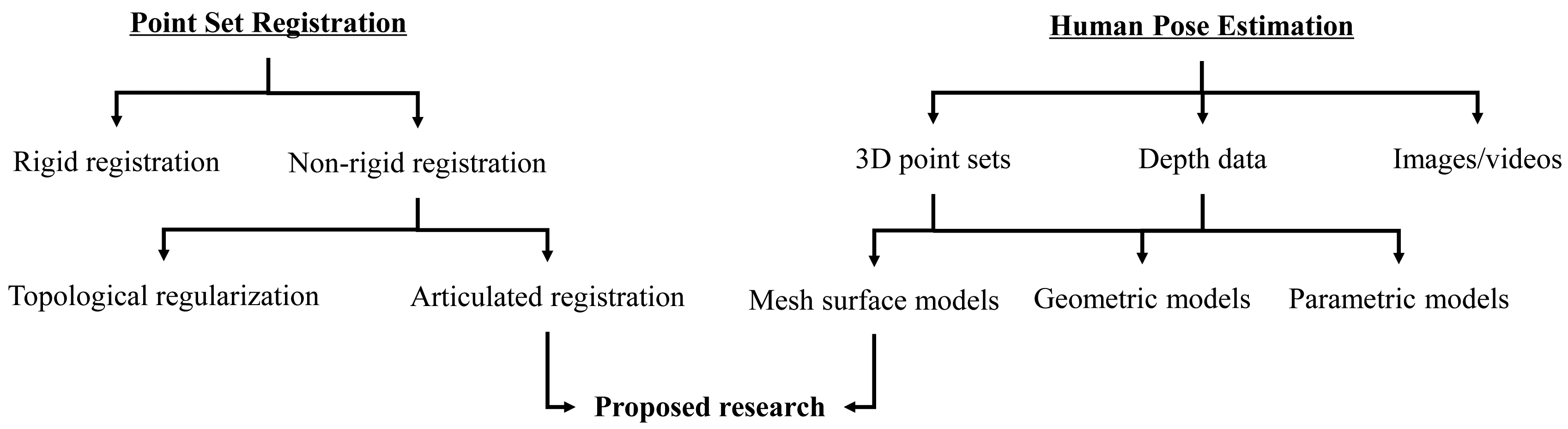
We provide a brief overview of the background of this research, which involves two separate, but related topics: point set registration and human pose estimation, as shown in Figure 1. Particularly, we focus on the recent research on human pose estimation from depth data, which has many practical applications due to the recent development of RGB-D cameras and other affordable range sensors.
Point set registration is a fundamental topic for many computer vision tasks. The registration techniques usually fall into two categories: rigid and non-rigid depending on the underlying transformation model. Iterative closest point (ICP) [24,25] is a classic rigid registration method, which iteratively assigns correspondence and then finds the least squares transformation by using the estimated correspondence. For non-rigid registration, shape features are commonly used for correspondence initialization [26–28] or directly involved in the matching process [29,30]. Recently, topology-aware approaches are becoming an important category where a Gaussian mixture model (GMM)-based probabilistic registration strategy is commonly used [23,31–36]. For example, a Gaussian radial basis functions (GRBF)-based displacement function with a global topological constraint, coherent point drift (CPD), was introduced in [33,34], which leads to a powerful and general GMM-based non-rigid registration algorithm. Two kinds of graph-based regularizations, which aim to improve the robustness to outliers and to preserve the intrinsic geometry, were incorporated in the CPD framework [37,38]. In [23], by jointly considering the global and local topological constraints, global-local topology preservation (GLTP) was proposed to deal with non-rigid and highly articulated deformations. As a special case of non-rigid registration, articulated structure registration is an active and interesting research topic due to its wide applications. Most existing approaches assume that the articulated structure is locally rigid (e.g., [16,17]) and often require good correspondence initialization or similar poses between the template and the target to avoid being trapped into local minima [16,22].
On the other hand, traditional human pose estimation research is mainly based on 2D images or videos [9], and there is a dramatic increase of research efforts on pose estimation from 3D data, including point sets and depth maps, due to the availability of various affordable 3D sensors. A key element in the problem of pose estimation is human body representation, and the often used models include mesh surface, geometric and parametric models. In this paper, we focus on the mesh model based representation, and human pose estimation is cast as a point set registration problem. The main challenge here is the large pose and shape variations between the template and observed target models, especially when there is no temporal information available, such as individual 3D laser scan data. An often used remedy to this problem is to involve some training data, an efficient classifier or data-driven features to initialize the registration process. For example, a 3D database, which contains a large number of mesh models along with embedded skeletons, was used in [22] to search for the most similar pose for a given input depth image based on which, CPD is performed for pose estimation by refining correspondences. In [13], the input depth image is matched to the template model by employing a pre-trained regression forest; then, joint positions are estimated by minimizing an energy function from predicted correspondences over the full body. In [39], an upper-body segmentation is first obtained from depth images, which is used to initialize AICP-based pose estimation. Additionally, human pose tracking was also recently studied intensively, which takes advantage of the smooth motion assumption and uses pose estimation in the previous frame to initialize the present one [18–20]. However, sequential depth data usually are noisy and incomplete due to significant self-occlusions and dramatic view changes, which lead to inaccurate or unstable pose estimation. Therefore, some constraints are introduced to improve the reliability of pose estimation. For example, some pose hypotheses are predicted to guide pose estimation in a new frame [19,40], which are created from detected feature points corresponding to anatomical landmarks. In [18,41], the pose hypothesis in the current frame is predicted by a linear third order autoregression model, which involves three previous estimated poses. It is worth mentioning that failure detection is a very important step for pose tracking. Some kinematics and physical constraints are used in [22,42] to detect failures after pose estimation and to make necessary corrections if needed.
Our research is deeply motivated and inspired by the aforementioned endeavors. We are specifically focused on three issues related to some previous limitations. The first is to deal with complex articulated non-rigid deformations caused by large pose and shape variations by a unique hybrid registration approach that does not require correspondence initialization and can deal with large pose variation. The second is to cope with self-occlusions and view changes in pose tracking by invoking a sequential template update strategy that does not require any feature detection or data segmentation. The third is to detect pose tracking failures during (not after) pose estimation by using a new segment volume validation technique after correspondence estimation, which is amenable to represent kinematic and psychical constraints.
3. Proposed Framework
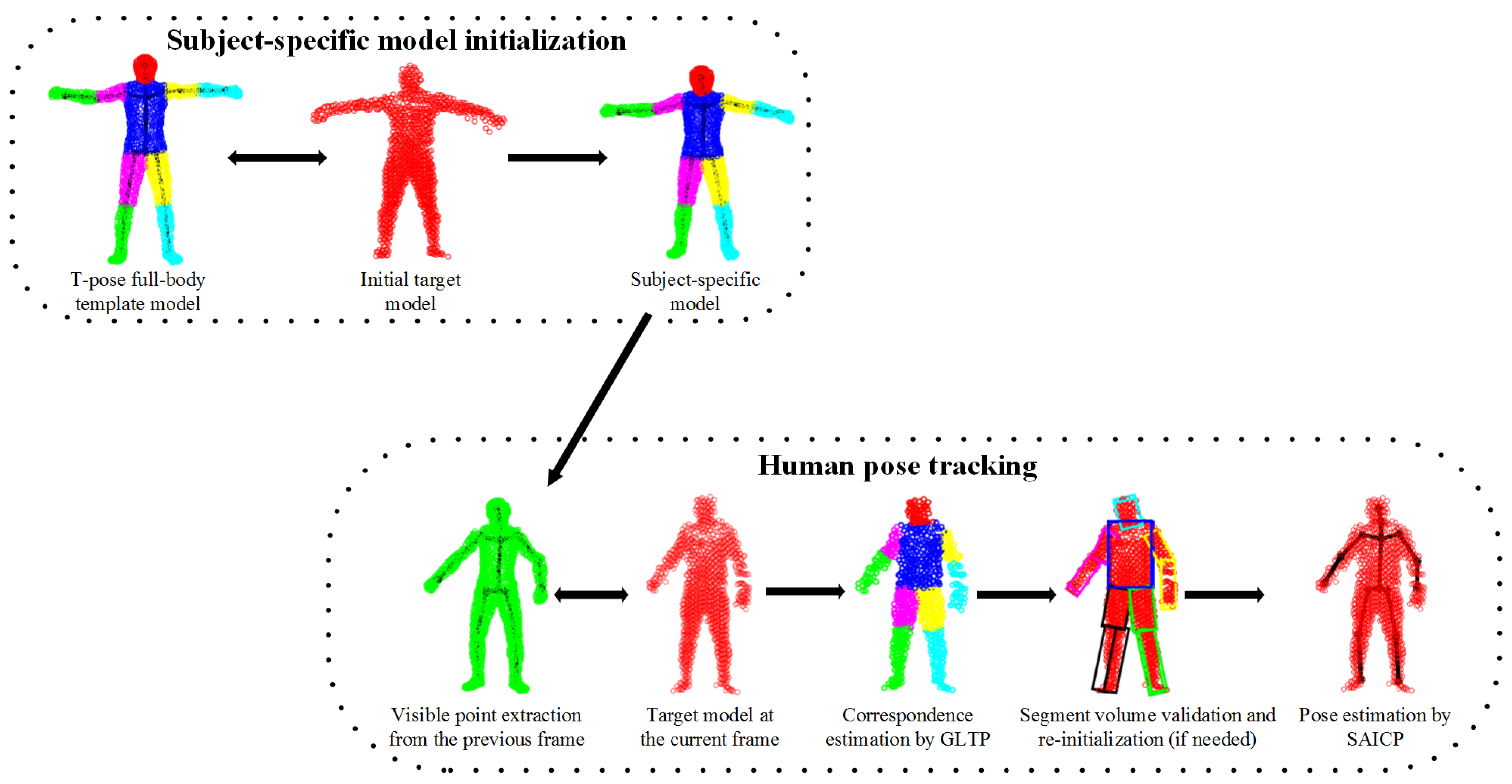
An overview of the proposed framework is shown in Figure 2, which involves five steps. First, we learn a subject-specific articulated model to initialize the body shape and size for a new subject. Second, visible point extraction is performed from the subject-specific model to create a partial template model, which either involves previous pose estimation or a “T-pose” template. Third, our recently proposed non-rigid registration algorithm (GLTP) is used for correspondence estimation from the observed target model. Fourth, segment volume validation is invoked to detect tracking failures and to trigger pose re-initialization if needed. Last, segment-aware AICP (SAICP) is used for articulated pose estimation by refining correspondence estimation at each segment iteratively. For 3D point sets, only Steps 1, 3 and 5 are needed; while for depth sequences, sequential pose tracking will involve all steps, and Steps 1, 2, 3 and 5 will support frame-by-frame pose estimation.
3.1. Subject-Specific Shape Initialization
A personalized articulated shape model is important for accurate and robust pose estimation due to the large body shape and size variabilities between the template and a target model. In [20], the personalized body shape represented by vertices of a given mesh is jointly controlled by a low-dimensional shape parameter vector learned from a laser scan database and a pose parameter vector through linear blend skinning. These shape parameters are obtained by optimizing a local cost function, which considers both Euclidean and the norm-based distances between matched points. In [18], after a global scaling initialization, the template shape is adapted sequentially after frame-wise pose estimation by segment-level size estimation and shape refinement along the norm direction.
In this work, we learn a subject-specific articulated model in two steps by involving a standard “T-pose” template Y (M × D) that represents M D-dimensional points {ym|m = 1, …,M} and an initial target Z (N × D), which denotes N D-dimensional points {zn|n = 1, …, N} from a subject (with four limbs fully stretched under a normal standing pose). Both Y and Z are preferred to have similar poses. Specifically, Y is extracted from a human mesh model with pre-labeled body segments and an articulated skeleton. Z is captured by a 3D sensor that should reflect a naturally stretched pose where most joints are revealed for accurate shape initialization.
In the first step, we apply the coherent point drift (CPD) algorithm [34] for non-rigid registration between Y and Z. CPD is a powerful Gaussian mixture model (GMM)-based registration approach, which enforces the GMM centroids to move coherently as a group to preserve the topological structure of the point set. The core of the CPD algorithm is that it defines the non-rigid transformation as a displacement function in a reproducing kernel Hilbert space (RKHS) with the spatial smoothness regularization defined as the Fourier domain norm. Additionally, it also proved that the optimal displacement function is represented by a linear combination of Gaussian kernel functions as:
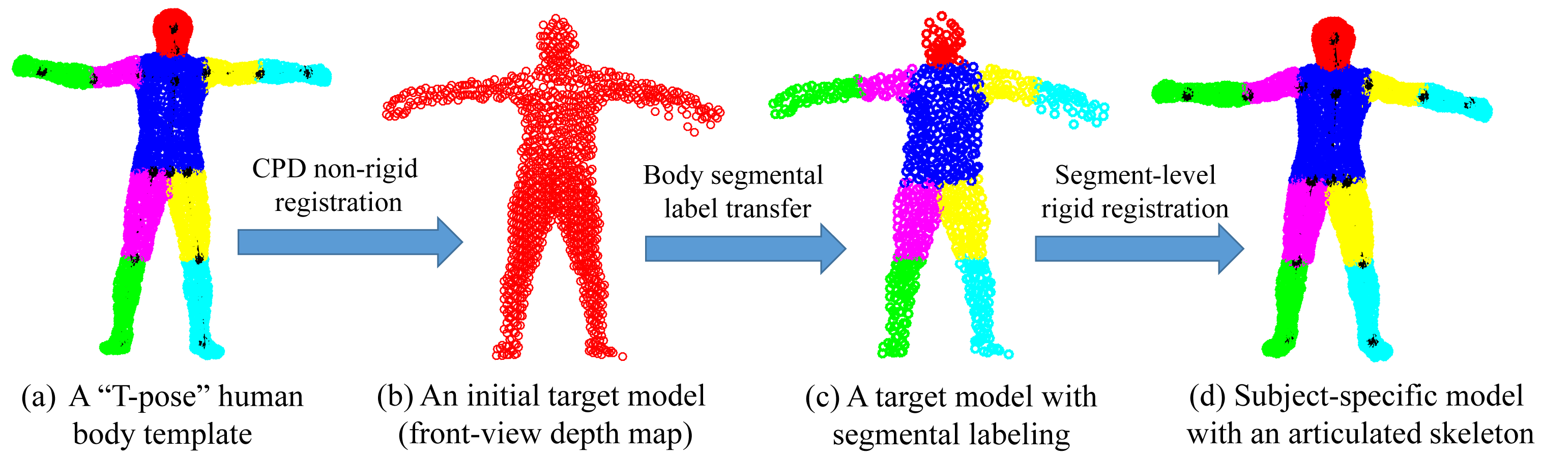
In the second step, we bake a skeleton in Z by transforming the skeleton of Y via segment-level rigid registration according to the estimated correspondences. As a result, a subject-specific articulated shape model Ẑ is learned that plays an important role for future pose estimation. In the case of depth data with incomplete front-view point sets, we introduce visible point extraction (to be discussed in the following) to obtain a front-view template prior to CPD registration. Then, after segment-level rigid registration, invisible parts will be transformed along with their visible counter parts to build a complete subject-specific model Ẑ. An example of subject-specific shape initialization is shown in Figure 3.
3.2. Visible Point Extraction
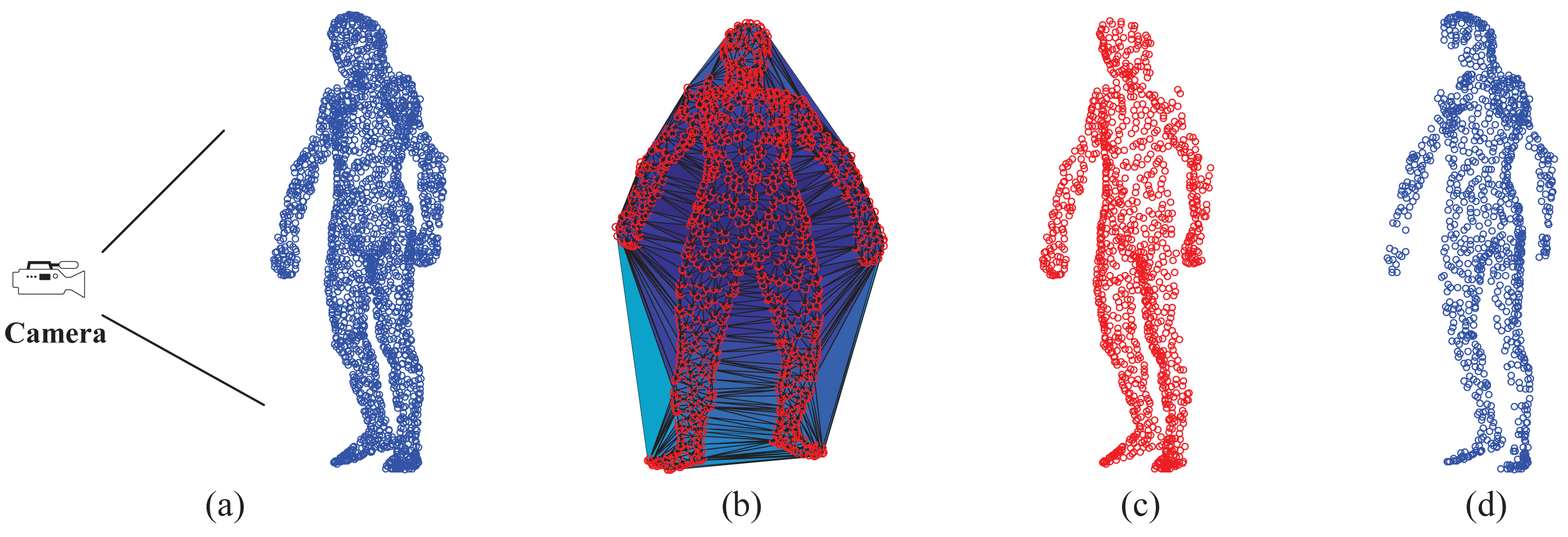
Visible point extraction is important to support depth map-based pose estimation, especially in the case of sequential depth data. This step requires the relative position between the full-body template model and the camera. In this work, we use the hidden point removal (HPR) operator [43] to detect visible points of a given template model. Given a point set A = {ai} and the viewpoint C (camera position), the HPR operator mainly has two steps to determine ∀ai ∈ A whether ai is visible from C. In the first step, we associate with A a coordinate system and set C as the origin. Then, we find the inverted point of each ai using spherical flipping [44] with the following equation:
3.3. Topology-Aware Non-Rigid Registration
The objective of this step is to estimate correspondences between a labeled template point set and any target point set with an arbitrary pose. This is critical for latter SAICP-based articulated pose estimation. Because the subject-specific model Ẑ may not be in a strict fully-stretched “T-pose”, it may not serve as a good template here. Therefore, in the case of individual point set registration, we always use the standard “T-pose” template, where all body segments are fully stretched, as shown in Figure 3a. In the case of sequential depth data, we can either use the standard “T-pose” template for every frame by treating each frame independently or invoke a tracking strategy by creating a new template from the pose estimation result of the previous frame. The latter one is more computationally efficient, but must be accompanied with tracking failure detection and may require re-initialization if needed. As those used in Section 3.1, we still use Y and X to denote the template and a new target point set, respectively, in the following.
Due to the possible highly articulated non-rigid deformation in X, traditional registration algorithms (e.g., CPD) may not be able to provide reliable correspondence estimation. Therefore, in this work, we use our previously proposed GLTP algorithm [23], which unifies two topologically complementary constraints, i.e., CPD-based global motion coherence and local linear embedding (LLE)-based local topology [45], into a GMM-based probabilistic registration framework. Specifically, the CPD-based motion coherence defined in Equation (2) is helpful to keep the overall spatial connectivity of a multi-part point set during the registration process, and the LLE-based local topological constraint is useful to preserve the neighborhood structure during non-rigid deformation. In this work, we present GLTP in the context of human pose estimation. For each point in Y, the local neighborhood is represented by the weighted linear combination of its pre-selected K nearest neighbors where the weights are obtained by minimizing the reconstruction error. Then, the LLE-based regularization term has the form:
3.4. Segment Volume Validation
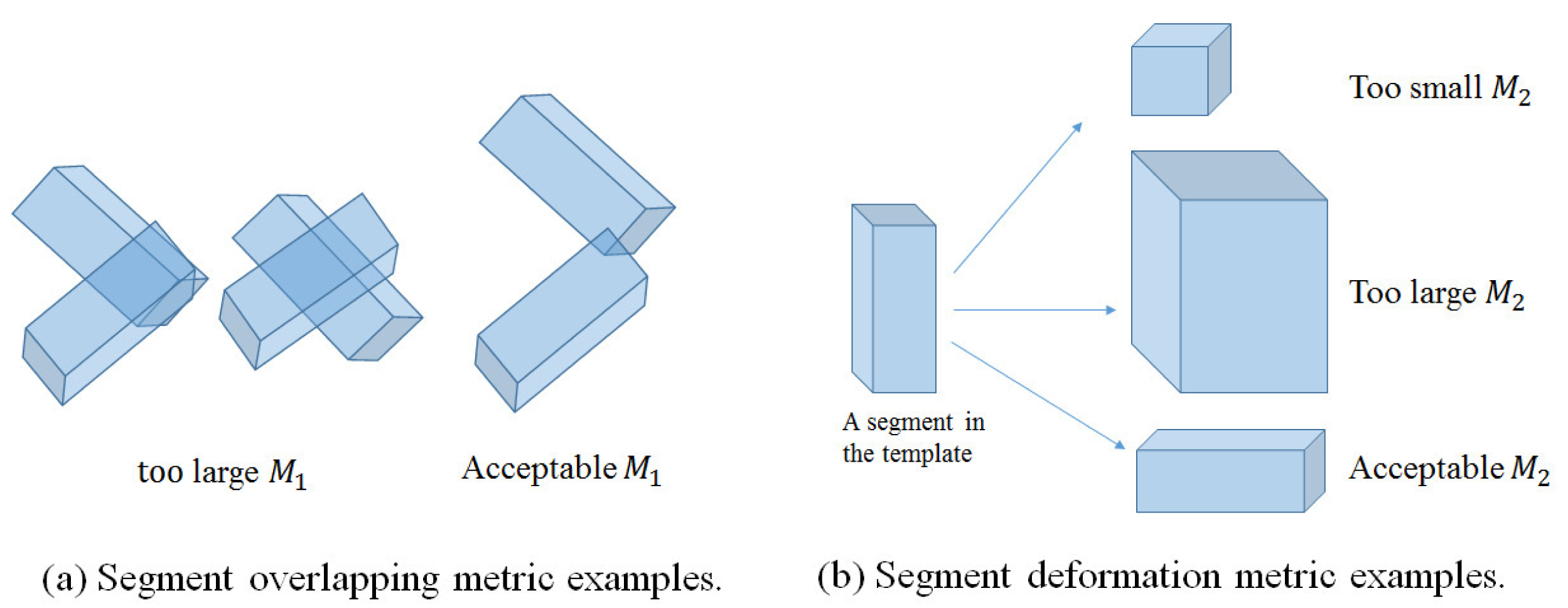
Although sequential pose tracking is efficient in dealing with depth sequences, it is important to validate the tracking result at every frame to prevent the error from propagating over frames. This step is especially important when there are significant and frequent self-occlusions due to dramatic pose and view changes. Traditionally, tracking validation is done based on the pose estimation results by applying some kinematic or physical constraints [22,42]. We propose an effective approach to detect tracking failures at an earlier stage (after GLTP and before SAICP). We first obtain the labeled point set X̂ from a given input point set X by transferring segment labels according to estimated correspondences. We then validate the segment volume for each body segment in X̂ represented by the minimum volume oriented bounding box (OBB) [47,48], where two metrics are involved as follows.
Segment overlapping metric (M1): This metric checks the overlapping ratios between every two body segments represented by OBBs in a labeled point set X̂ of P segments, as defined below:
Segment volume deformation metric (M2): This metric measures the volume deformation of a segment after GLTP-based non-rigid registration:
As shown in [23,49], GLTP works very well in most depth sequences we tested, but there are still three possible challenging cases for which GLTP may fail with invalid correspondence estimation, as shown in Figure 6: (1) Case I: some segments become invisible in the current frame due to the view change (e.g., the subject is making a turn from the frontal view to the side view, Figure 6b); (2) Case II: some segments suddenly reappear after being absent for some frames due to the view change (e.g., the subject is turning to the frontal view from the side-view, Figure 6c); (3) Case III: there are significant self-occlusions between two adjacent frames due to large pose variation and fast motion, which causes a large number of missing points in the target point set (e.g., the subject is making a quick high kick, Figure 6d). We will discuss how to detect these three cases by the two proposed metrics and how to remedy accordingly. The thresholds of M1 and M2 are given in the experiment.
The first case can be detected if M1 is too large for a particular segment or the number of points in a segment becomes too small (e.g., less than 25%). Correspondingly, we update the template obtained from the previous frame by declaring this segment “invisible” and then re-perform GLTP-based non-rigid registration. As shown in Figure 6b, there are significant overlaps between the right arm (purple) and the torso (blue) and between the right (black) and left (green) legs. To mitigate this problem, those segments will not be involved during GLTP registration for re-initialization, and they will deform along with their parents according to their rotations in the previous frame during the latter articulated registration.
The second case can be checked by both using M1 and M2. When there are a couple of limbs that were occluded in previous frames and re-appear in the current frame, those limbs will be likely overlapped with other segments, leading to large M1 for those reappearing segments. Furthermore, part of the reappearing segments could be mistakenly included in wrong segments (the torso in most cases) whose volumes become much larger, leading to large M2. As shown in Figure 6c, the reappearing right arm (purple) is merged into the torso (blue), resulting in large M1, and meanwhile, both the torso and head (cyan) have a large volume change to cover part of the right arm. The remedy for this case is to use the “T-pose” template to re-perform GLTP-based registration for re-initialization.
The third case is the “worst case scenario” when most segments have invalid M1 and M2. This case is very rare in practice, and it is usually due to large self-occlusions, as shown in Figure 6d where the right upper-leg (black), the right arm (purple) and part of the torso (blue) are occluded when the subject is making a quick high kick. In this case, registration-based approaches usually will not work well, and we invoke a simple, yet effective approach to recover the underlying pose by imposing pose continuity across frames and by introducing physical constraints in the step of articulated registration to be introduced in the next section.
3.5. Articulated Registration for Pose Estimation
This last step involves two labeled point sets. One is the labeled target X̂ of an arbitrary pose, and the other is the subject-specific model Ẑ, which is expected to have the same body shape and size as X̂. The goal is to perform pose estimation of X̂ by matching with Ẑ, which includes P rigid body segments {S1, ⋯, SP} connected by the skeleton model. Because both X̂ and Ẑ are registered with the “T-pose” template Y, we can initialize their correspondences by referring to the same template. Then pose estimation is converted to find the rigid transformation for each body segment Sp (p = 1, …, P), which can be represented collectively by:
The original AICP algorithm in [16] adopts a divide-and-conquer strategy to iteratively estimate an articulated structure by assuming that it is partially rigid. In each iteration, the articulated structure is split into two parts by a joint, which is selected randomly or cyclically; then, the classic rigid ICP is performed locally on one of these two parts. AICP works effectively when the template and target have similar segmental configurations (i.e., similar poses), which may not be true in human pose estimation. In our case, given reliable correspondence estimation by GLTP, we follow a more flexible and efficient scheme to construct a partial rigid body part by selecting single or several connected segments. We develop a new segment-aware AICP (SAICP) algorithm to find the rigid transformations for all segments by optimizing Equation (11) in a way that reflects segment-level articulated motion. The main idea is to take advantage of GLTP's output by starting from the root (the torso) and head, which are relatively stable, and then following along the tree-structured skeleton according to the connectivity between segments, as shown in Figure 7a. This allows us to treat the limbs in a particular order, upper, lower and whole, as shown in Figure 7b, and it is efficient to update the rigid transformations of four limbs simultaneously. It is worth mentioning that the correspondences at each segment will be updated during each iteration when the segment label information of X̂ and Ẑ is also used for the minimum distance search.
The SAICP algorithm is discussed in detail as follows. Let Ψ = {S1, ⋯, Sp}, which represents a body part composed of p (p ≤ P) connected segments (with MΨ, points) along the articulated structure from the labeled target Ẑ. We have the objective function defined for this body part as:
| Algorithm 1 The Pseudo-Code of the Proposed Pose Estimation Framework. |
| Input: “T-pose” template Y, an initial target Z and T sequential depth frames X1:t |
| Output: A sequence of deformed full-body models Ẑt (t = 1, …, T) with estimated joint positions |
| GLTP Initialization: ω = 0.1, K = 10, α0 = 10, β = 2, λ0 = 5 × 10⁶ |
Shape Initialization:
|
For each depth frame Xt (t = 1, …, T) do
|
| End for |
4. Experiments
Our proposed framework does not involve any training data and is evaluated on two publicly available datasets, 3D SCAPE (Shape Completion and Animation of People) data [11] (captured by a 3D laser scanner) and SMMC-10 (Stanford Time-of-Flight Motion Capture) data [50] (captured by a Swissranger SR4000 time-of-flight (ToF) camera at 25 fps and a resolution of 176 × 144). Below, we present the results corresponding to two datasets, separately.
4.1. Experiments for the SCAPE Dataset
4.1.1. Point Set Data Preparation
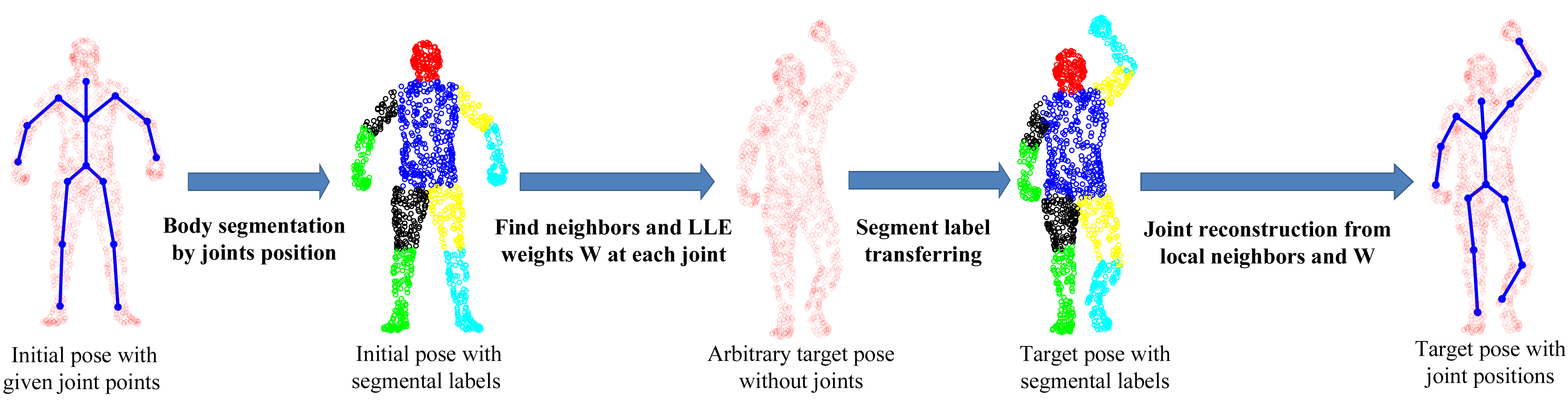
The SCAPE dataset contains a series of 3D scan data captured from one male subject (the only one publicly available under different poses), which are fully registered (the index of each point stays the same across all poses). It has one initial pose with ground-truth joint positions. To perform quantitative comparative analysis, we develop a simple, yet effective four-step approach to generate the ground-truth joint positions for all other poses, as shown in Figure 8. First, we perform body segmentation for the initial pose according to joint positions. Second, for each joint, we find a set of neighboring points around the joint area between two connected body segments and compute LLE weight coefficients to represent each joint locally. Third, we transfer the segmental labels from the standard pose for any new target pose. Fourth, we use LLE weight coefficients and the associated neighboring points, which share the same indexes as those in the initial pose, to reconstruct each joint position in the target pose. In this way, all poses will have the ground-truth joint positions created for performance evaluation.
4.1.2. Experimental Results: Shape Initialization
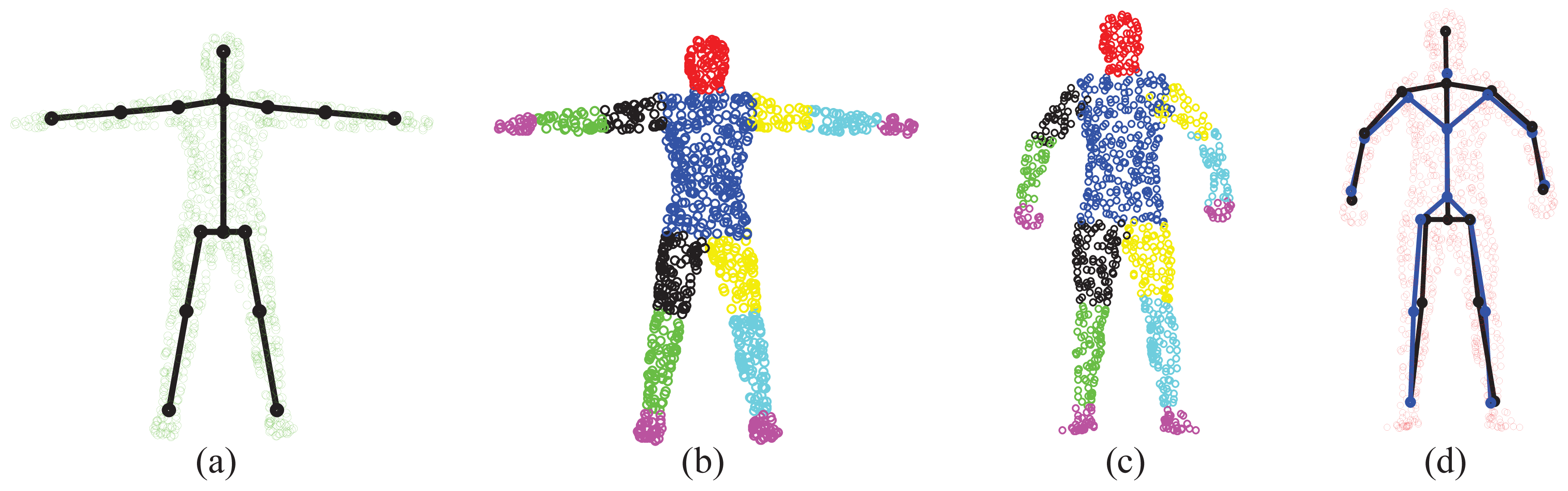
The “T-pose” template used for the SCAPE data is modified from the MotionBuilder humanoid model, which has a skeleton and labeled body segments, as shown in Figure 9a, b, respectively. Given an initial pose from the SCAPE data that is close to the “T-pose”, we use the two-step approach discussed in Section 3.1 for shape initialization. Then, we obtain labeled body segments in Figure 9c and the estimated skeleton (joint positions) in Figure 9d. Compared with the ground-truth skeleton, the average error of joint positions is 2.88 cm. The subject-specific shape model shown in Figure 9d will be used in the following two experiments regarding correspondence estimation and pose estimation.
4.1.3. Experimental Results: Correspondence Estimation
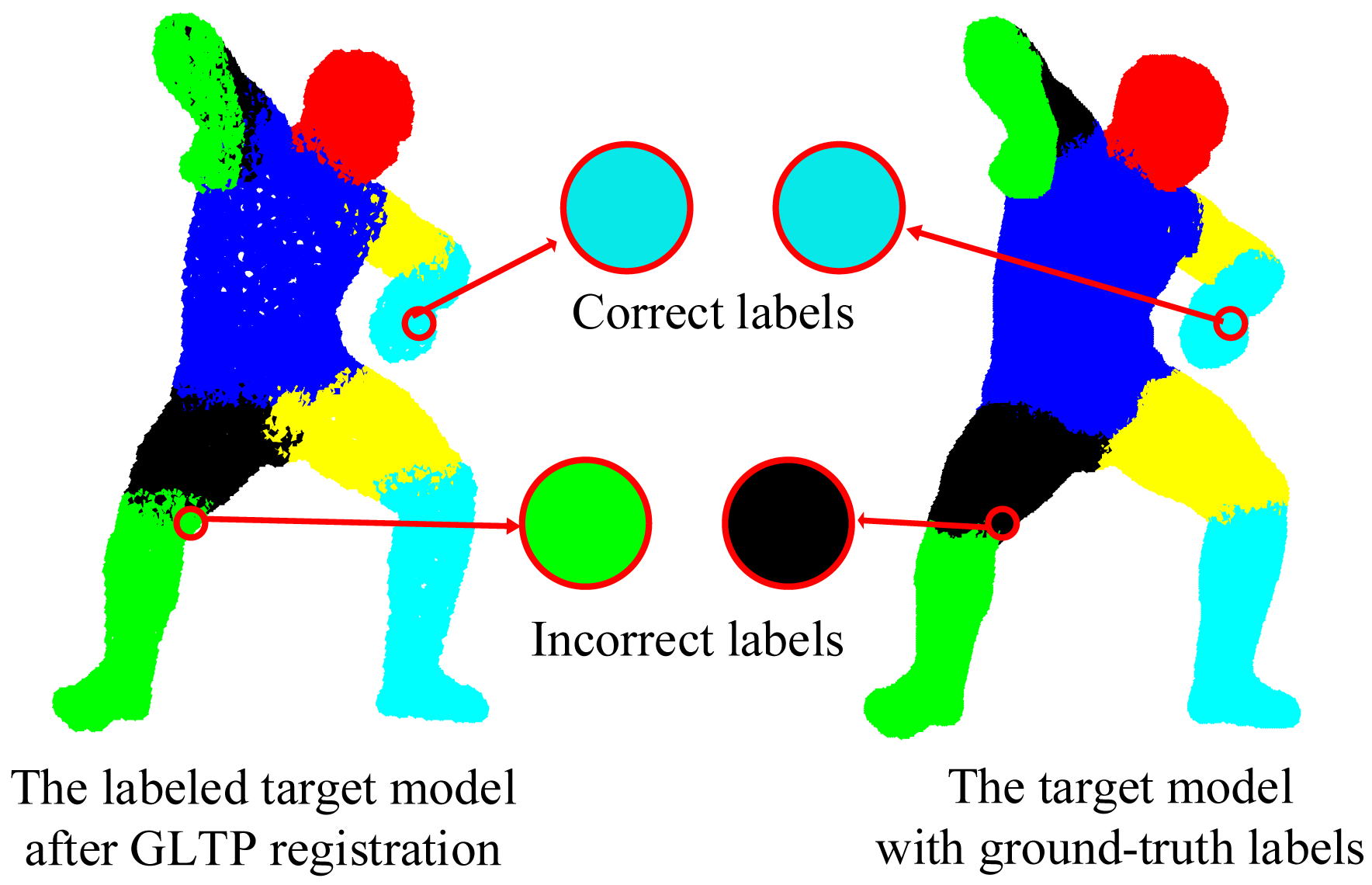
We validate the proposed framework on 38 target poses from the SCAPE dataset, most of which have strong non-rigid articulation compared with the template, which makes it a challenging test set. In this case, visible point extraction and segment volume validation are not involved. Since the template and target models are captured from different subjects and also have different numbers of points, it is difficult to obtain the ground-truth correspondences. Thus, a quantitative result in terms of registration error is not available in this experiment. Instead, we use the accuracy of body segment labeling to evaluate the registration performance. During data preparation, we have obtained the ground-truth segment labels for all target poses. For each point in the template model, we propagate its segment label to the corresponding point in the target model by the estimated correspondence. If this assigned segment label is the same as the ground-truth label, we treat it as the correct segment label, as shown in Figure 10. Then, the labeling accuracy for each target pose is calculated as the percentage of the points with correct segment labels over all labeled points.
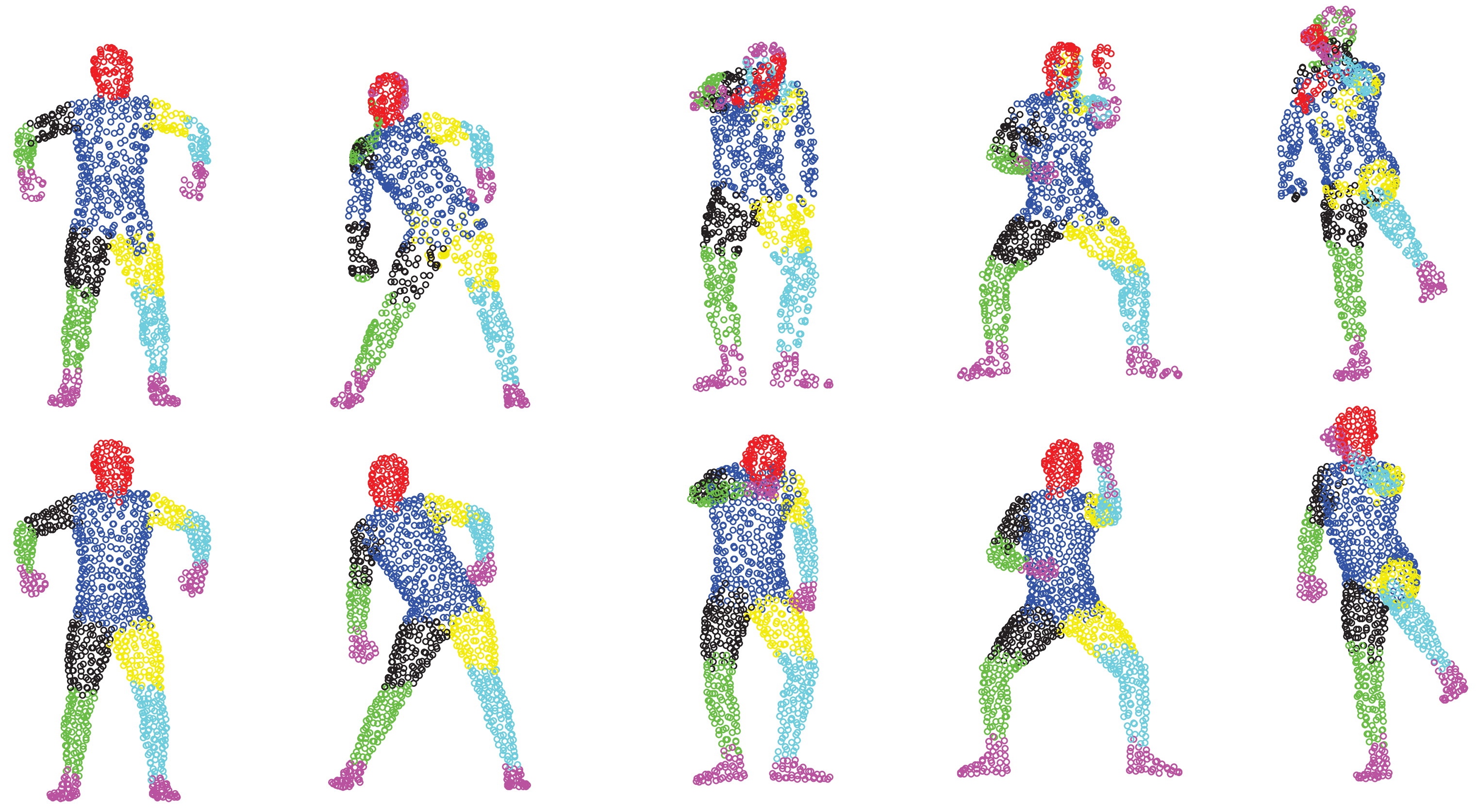
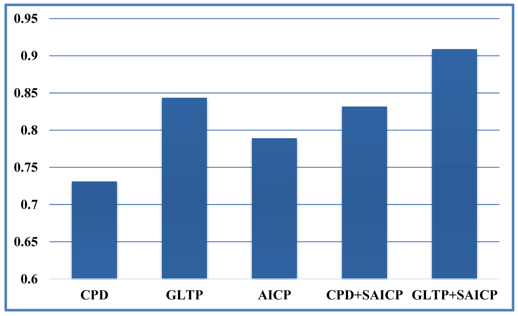
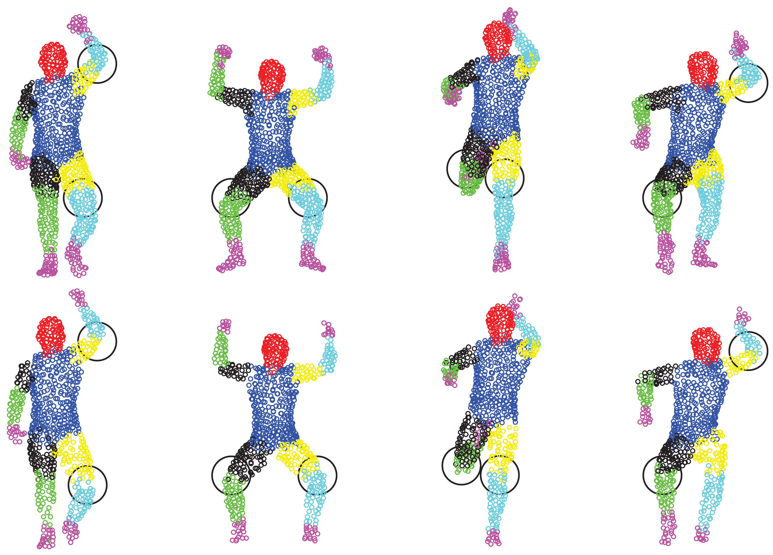
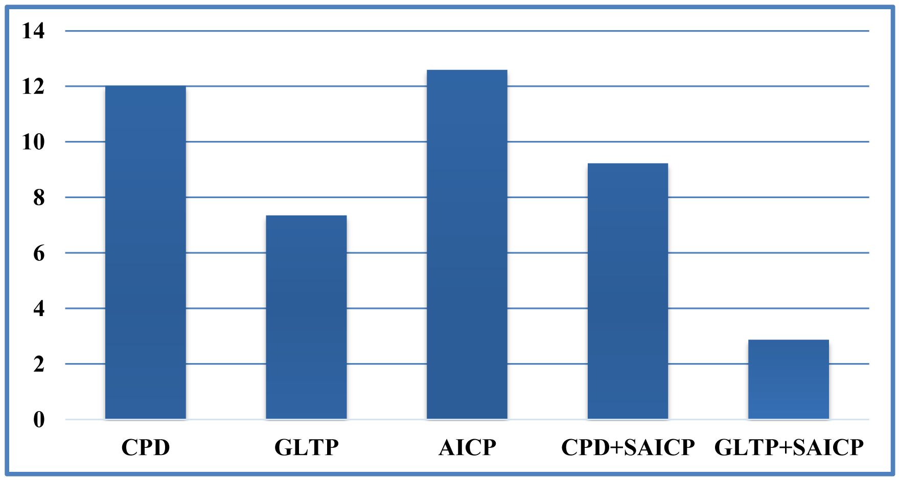
We first show some qualitative results of GLTP (α = 10, β = 2, λ = 5 × 10⁶ and K = 10) by comparing with CPD in Figure 11 in terms of segment labeling accuracy. When articulated deformation is not significant between the template and target, such as the first pose, both CPD and GLTP perform well. However, in the cases of highly articulated deformations, e.g., Poses 2 to 5, significant labeling errors are observed around the head, limbs and body joints in the CPD results. On the other hand, GLTP provides stable segment label estimation across all poses. However, the results around limb joints are still not very reliable. We further perform the comparative analysis (averaged over 38 poses) with CPD, GLTP and AICP [16] in Figure 12, which shows that GLTP is the best one among all three, and AICP is better than CPD due to the fact that its locally rigid assumption is suitable for 3D human data. Figure 12 shows the labeling accuracy of body segments of our approach (GLTP + SAICP). It is shown that a significant improvement is achieved by using GLTP and SAICP jointly (GLTP + SAICP), which is also better than the one using CPD and SAICP together (CPD + SAICP). We visualize some labeling refinement results in Figure 13, where obvious improvements are seen around limb joints.
4.1.4. Experimental Results: Pose Estimation
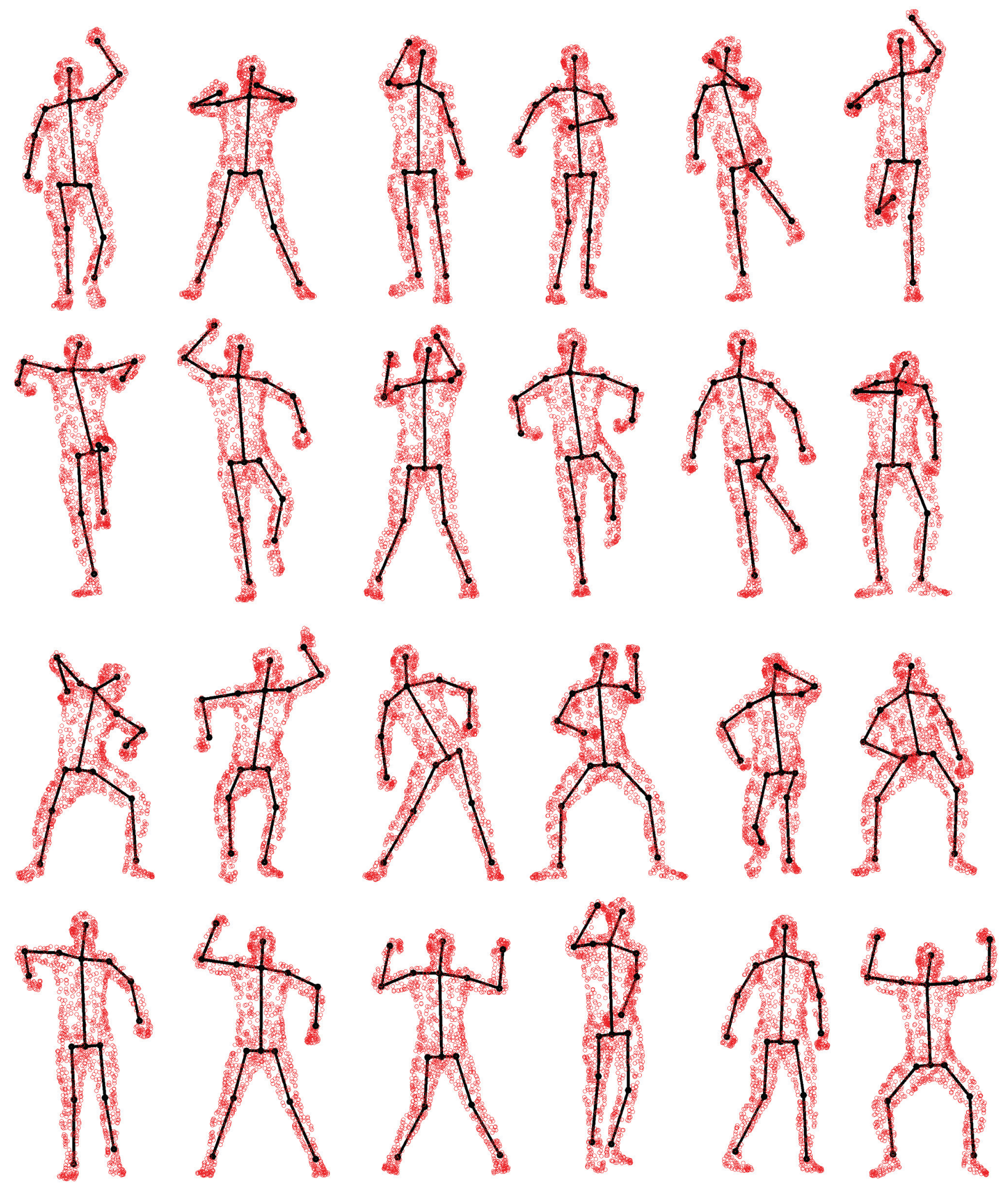
We compare pose estimation results in terms of joint position error (cm) in Figure 14. We can see that directly using the estimated corresponding points to compute joint positions cannot achieve a reasonable pose estimation result. Although compared with CPD, GLTP provides much better results, the correspondence estimation around the connection area between two adjacent segments is not reliable due to the lack of segmental information during the registration, which leads to inaccurate pose estimation. As we mentioned before, without a good initialization, AICP is usually trapped into local minima, which results in large estimation errors. Our framework significantly outperforms other options, including CPD, GLTP, AICP and CPD + SAICP, showing the effectiveness of GLTP for correspondence estimation and the necessity of SAICP for pose estimation, which involves the segmental information to refine the GLTP results. We also present some pose estimation results in Figure 15.
4.1.5. Experimental Results: Further Discussion
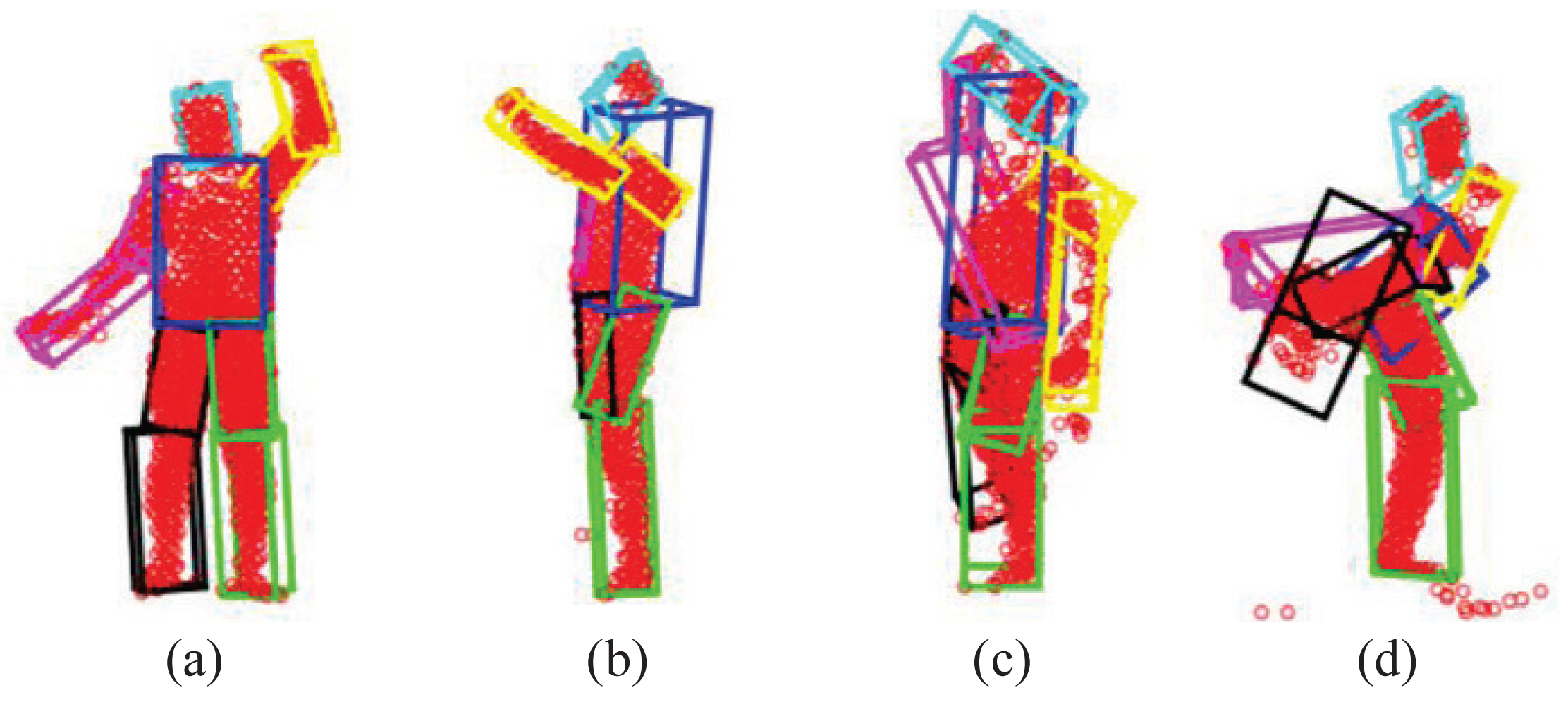
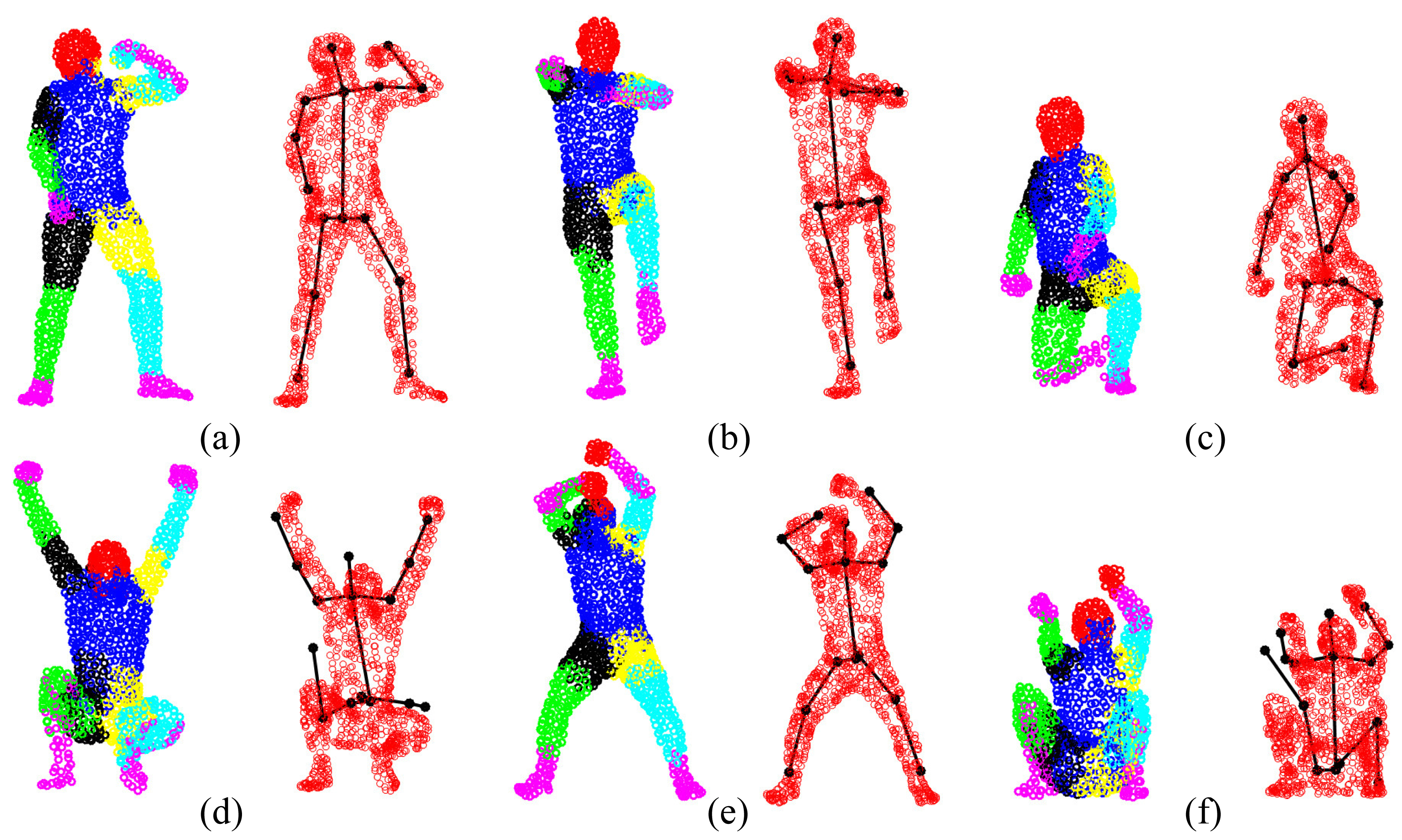
The GLTP registration algorithm, which initializes the correspondences for SAICP-based articulated pose estimation, plays a critical role in the whole flow. Since GLTP uses the Euclidean distance to assign correspondences, it may not be reliable or valid in two challenging cases. First, when there is a strong pose articulation in the point set compared with the standard “T-pose” template, the EM-based GLTP optimization could be trapped into local minima, resulting in some body segments being wrongly labeled, which might be corrected by SAICP during pose estimation. Second, when some body segments are too close (the head and hands) or even merged (lower/upper legs), the shortest distance is no longer valid in those segments, leading to wrong correspondence estimation, which can only be partially corrected by SAICP due to large labeling errors. We further show six challenging cases in Figure 16, where the first row shows three examples of the first case and the second row presents three examples of the second case.
4.2. Experiments for the SMMC-10 Dataset
4.2.1. Data Preparation
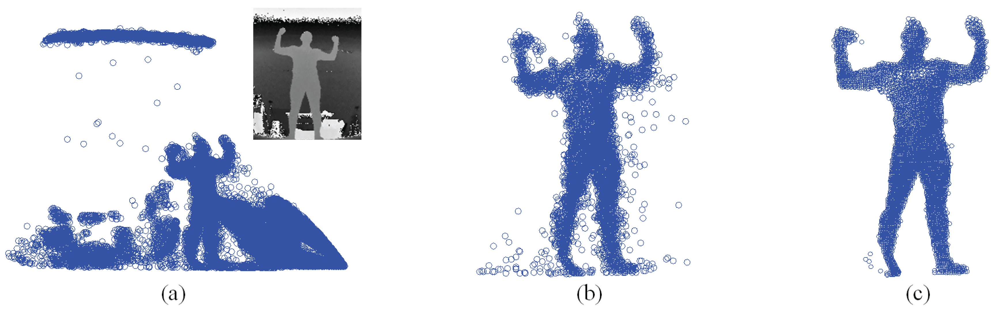
The SMMC-10 dataset contains 28 depth image sequences (numbered 0 to 27) from the same subject with different motion activities, and it provides the ground-truth marker locations. The input depth image cannot be used directly, due to noise/outliers and undesirable background objects. Therefore, we performed three pre-processing steps to make the depth data ready for pose estimation, which include body subtraction by depth thresholding, a modified locally optimal projection (LOP) algorithm for denoising [22] and outlier removal by limiting the maximum allowable distance between two nearest points. Figure 17 shows an example of depth pre-processing for the SMMC-10 dataset. The “T-pose” template (around 2000 points) in this experiment is from [22], which has a built-in skeleton (Figure 18a) along with labeled body segments (Figure 18b). We selected one depth image with “T-pose” from Sequence 6 for shape initialization, which is given in Figure 18c, and the learned subject-specific shape model with a baked-in skeleton and labeled segments is shown in Figure 18d.
4.2.2. Experimental Results: Segment Volume Validation
In practice, we found that both M1 and M2 have very distinct values in the passing and failing cases, indicating their sensitivity for volume validation. In this work, we chose M1 and M2 to be 0.3 and 10, respectively. The threshold of the torso's M2 is 1.4 to reflect the maximum allowable height change. In all 28 testing sequences, the total frame-wise pass rate is over 98%, and there are 1.89% of frames that require re-initialization (Case I or II). Twenty one out of 28 sequences have a 100% passing rate, and Case III is only detected for a few frames in Sequence 25. Some validation examples are given in Figure 19, which shows a passed case (the first row) and three failed cases: (1) In the second row (Case I), the right arm is visible in the previous frame (red points in column (b)), but invisible in the current frame (column (a)). The right arm has invalid M1 (column (d)). The re-initialization result (re-do GLTP with a template where the right arm is set as invisible) is shown in column (e). (2) In the third row (Case II), the left arm is trapped in the torso, and the right arm has an enlarged volume to cover the points from both arms (column (c)). The left arm has invalid M1, and the right arm has invalid M2 (column (d)). Column (e) shows the re-initialization result with the recovered left arm after GLTP registration using the “T-pose” template. (3) In the fourth row (Case III), both left and right arms and part of the torso are missing, caused by large self-occlusions. Correspondence estimation results are invalid (column (c)), leading to invalid M1 and M2 for most segments (column (d)). Column (e) shows the pose estimation result by using pose continuity and physical constraints.
4.2.3. Experimental Results: Pose Estimation
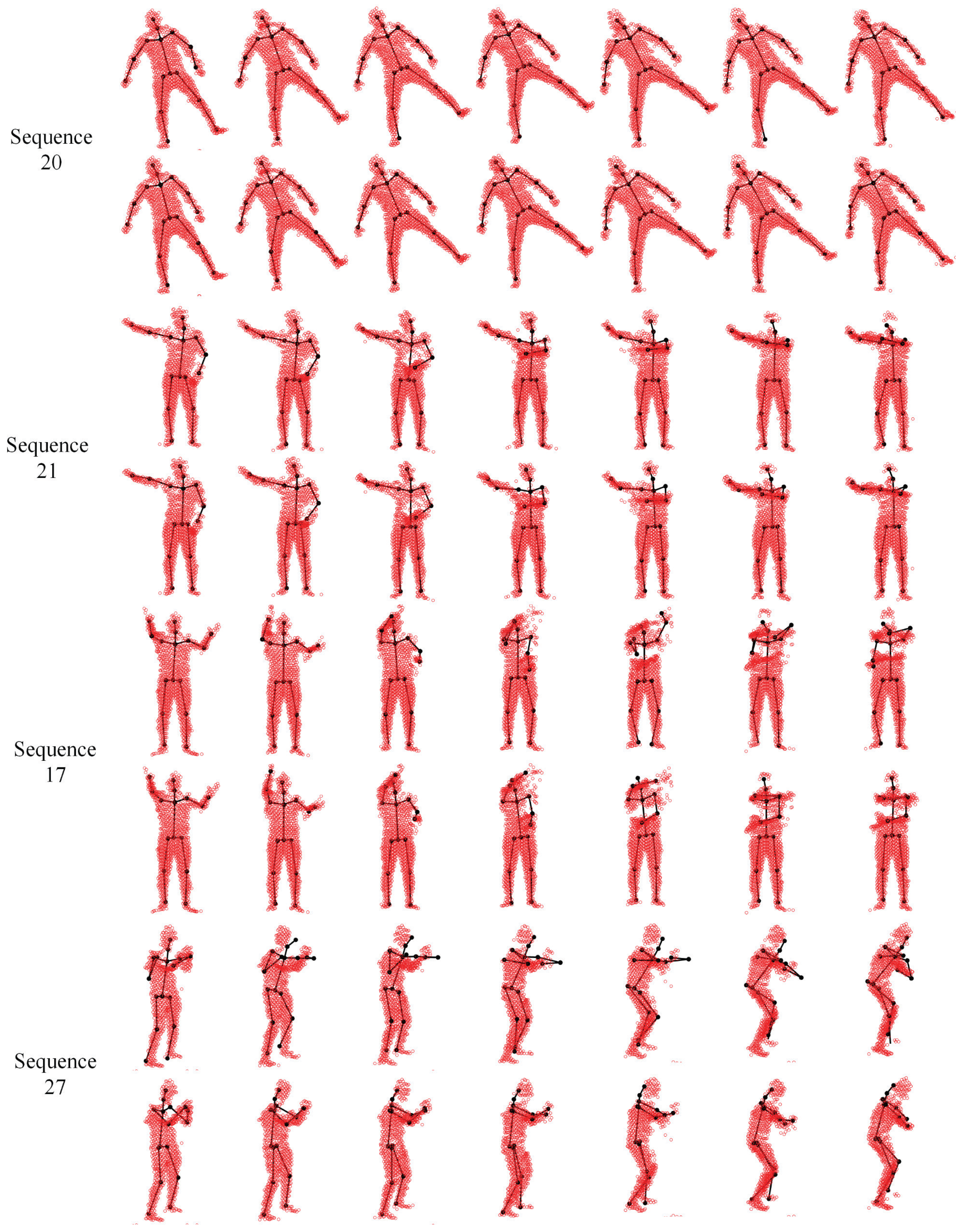
We evaluate our proposed pose estimation framework in two settings. The first one treats each frame independently with the same “T-pose” template (the same as [49]), and the other one involves the tracking strategy by updating the template sequentially via visible point extraction from the previous pose estimation result. Out of 28 depth sequences, the subject keeps a stable view point in all but two (24 and 27) sequences. In Sequences 24 and 27, the subject undergoes significant view changes. In the the first setting, the frontal view “T-pose” template is used at each frame when all body segments are visible, and the large pose variation between the template and target models may lead to inaccurate pose estimation results in some challenging frames. The pose tracking scheme introduced in the second setting is expected to be more effective and accurate to deal with sequential depth data where segment volume validation plays an important rule to ensure a smooth and valid tracking result. Some qualitative results on four selected sequences are shown in Figure 21, where the first and second rows show the results from two pose estimation settings (without and with tracking).
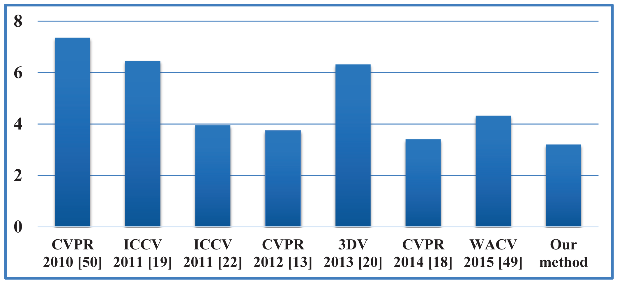
Our proposed framework is also compared against some recent state-of-the-art algorithms [13,18–20,22,49,50] in terms of the error between each estimated joint and its corresponding ground-truth marker. Given a sequence with Nf frames and Nj joints, the joint estimation error is defined as:
4.3. Computational Complexity
The computational loads of the three registration algorithms (CPD, GLTP and SAICP) involved in the proposed framework are shown in Table 1. CPD is only performed once for personalized body shape initialization, and GLTP shares a similar EM algorithm as CPD. Their computational costs could be reduced by using fast implementations [34], then the cost for computing P in CPD and GLTP, which involves the calculation of the sum of exponentials, could be reduced from O(MN) to O(M + N). Pose tracking reduces the computational load of GLTP significantly By using the low-rank matrix approximation, the cost for solving the linear system defined in Equation (7) to find W in GLTP could be lowered from O(M3) to O(R3), where R ≪ M is the lower rank value. Using the K-D tree to search for nearest neighbors [24] in GLTP and SAICP, the cost could be further decreased form O(M2) to O(M log(M)).
In practice, the algorithm speed depends on the numbers of points in the template and targets (around 1000 points for each) as well as the iteration numbers in GLTP and SAICP. The tracking strategy greatly reduces the number of iterations needed in GLTP by providing a good initialization for sequential registration. Also, due to reliable correspondence estimation from GLTP, SAICP only needs a few iterations to converge for each segment. Our algorithm was implemented in an un-optimized MATLAB code. For depth sequences, the running time is around 10 s (without tracking) or 3 s (with tracking) per frame on a PC with Intel i7 CPU 3.40 GHz and 32GB RAM. The proposed algorithm can be speeded up significantly by GPU acceleration with C/C++ implementation.
5. Conclusions
We propose a new generative framework for 3D human pose estimation from point sets captured by laser scanners or depth cameras. Without any initialization or training data, the proposed approach can handle complex articulated motions by combining two registration techniques in a complimentary way. One is the global-local topology preservation (GLTP) algorithm, which aims at non-rigid and articulated deformation, and the other one is the segment-aware AICP (SAICP) algorithm that takes advantage of reliable correspondence estimation by GLTP for articulate pose estimation. Furthermore, to handle sequential depth data, which may have missing data caused by self-occlusions and view changes, we introduce an efficient tracking strategy where two new techniques, e.g., visible point extraction and segment volume validation, are developed to support sequential registration. The experimental results on benchmark 3D laser scan and depth datasets demonstrate the effectiveness of the proposed framework.
Acknowledgements
This work is supported in part by the Oklahoma Center for the Advancement of Science and Technology (OCAST) under Grant HR12-30 and the National Science Foundation (NSF) under Grant NRI-1427345.
Author Contributions
Song Ge developed the algorithm, conducted the experiments, analyzed the results and participated in writing the paper. Guoliang Fan planned and supervised the research, analyzed the results and participated in writing the paper.
Conflicts of Interest
The authors declare no conflict of interest.
References
- Perez-Sala, X.; Escalera, S.; Angulo, C.; Gonzalez, J. A survey on model based approaches for 2D and 3D visual human pose recovery. Sensors 2014, 14, 4189–4210. [Google Scholar]
- Escalera, S. Human behavior analysis from depth maps. Proceedings of the International Conference on Articulated Motion and Deformable Objects, Mallorca, Spain, 11–13 July 2012; pp. 282–292.
- Ye, M.; Zhang, Q.; Wang, L.; Zhu, J.; Yang, R.; Gall, J. A survey on human motion analysis from depth data. In Time-of-Flight and Depth Imaging. Sensors, Algorithms, and Applications; Grzegorzek, M., Theobalt, C., Koch, R., Kolb, A., Eds.; Springer-Verlag: Berlin, Germany, 2013; pp. 149–187. [Google Scholar]
- Xbox One, Avaliable online: http://www.xbox.com/en-US/xbox-one (accessed on 8 May 2015).
- Sanmartín, G.; Flores, J.; Arias, P.; Cudeiro, J.; Méndez, R. Motion capture for clinical purposes, an approach using primesense sensors. Proceedings of International Conference on Articulated Motion and Deformable Objects, Mallorca, Spain, 11–13 July 2012; pp. 273–281.
- Gasparrini, S.; Cippitelli, E.; Spinsante, S.; Gambi, E. A depth-based fall detection system using a kinect sensor. Sensors 2014, 14, 2756–2775. [Google Scholar]
- Jalal, A.; Kamal, S.; Kim, D. A depth video sensor-based life-logging human activity recognition system for elderly care in smart indoor environments. Sensors 2014, 14, 11735–11759. [Google Scholar]
- Plantard, P.; Auvinet, E.; Pierres, A.L.; Multon, F. Pose estimation with a kinect for ergonomic studies: Evaluation of the accuracy using a virtual mannequin. Sensors 2015, 15, 1785–1803. [Google Scholar]
- Moeslund, T.B.; Hilton, A.; Kruger, V. A survey of advances in vision-based human motion capture and analysis. Comput. Vis. Image Underst. 2006, 104, 90–126. [Google Scholar]
- Elgammal, A.; Lee, C.S. Inferring 3D body pose from silhouettes using activity manifold learning. Proceedings of IEEE Conference on Computer Vision and Pattern Recognition, Washington DC, USA, 27 June–2 July 2004; pp. 681–688.
- Anguelov, D.; Srinivasan, P.; Koller, D.; Thrun, S.; Rodgers, J.; Davis, J. SCAPE: Shape completion and animation of people. ACM Trans. Gr. 2005, 24, 408–416. [Google Scholar]
- Shotton, J.; Fitzgibbon, A.; Cook, M.; Sharp, T.; Finocchio, M.; Moore, R.; Kipman, A.; Blake, A. Real-time human pose recognition in parts from single depth images. Proceedings of IEEE Conference on Computer Vision and Pattern Recognition, New York, NY, USA, 20–25 June 2011; pp. 1297–1304.
- Taylor, J.; Shotton, J.; Sharp, T.; Fitzgibbon, A.W. The vitruvian manifold: Inferring dense correspondences for one-shot human pose estimation. Proceedings of IEEE Conference on Computer Vision and Pattern Recognition, Providence, RI, USA, 16–21 June 2012; pp. 103–110.
- Burke, M.; Lasenby, J. Fast upper body joint tracking using kinect pose priors. Proceedings of the International Conference on Articulated Motion and Deformable Objects, Palma de Mallorca, Spain, 16–18 July 2014; pp. 94–105.
- Demirdjian, D. Combining geometric- and view-based approaches for articulated pose estimation. Proceedings of European Conference on Computer Vision, Prague, Czech Republic, 11–14 May 2004; pp. 183–194.
- Pellegrini, S.; Schindler, K.; Nardi, D. A generalization of the ICP algorithm for articulated bodies. Proceedings of British Machine Vision Conference, Leeds, UK, 1–4 September 2008; pp. 87.1–87.10.
- Horaud, R.; Forbes, F.; Yguel, M.; Dewaele, G.; Zhang, J. Rigid and articulated point registration with expectation conditional maximization. IEEE Trans. Pattern Anal. Mach. Intell. 2011, 33, 587–602. [Google Scholar]
- Ye, M.; Yang, R. Real-time simultaneous pose and shape estimation for articulated objects using a single depth camera. Proceedings of IEEE Conference on Computer Vision and Pattern Recognition, Columbus, OH, USA, 23–28 June 2014; pp. 2353–2360.
- Baak, A.; Müller, M.; Bharaj, G.; Seidel, H.; Theobalt, C. A data-driven approach for real-time full body pose reconstruction from a depth camera. Proceedings of IEEE International Conference on Computer Vision, Barcelona, Spain, 6–13 November 2011; pp. 1092–1099.
- Helten, T.; Baak, A.; Bharaj, G.; MÃijller, M.; Seidel, H.; Theobalt, C. Personalization and evaluation of a real-time depth-based full body tracker. Proceedings of International Conference on 3D Vision, Seattle, WA, USA, 29 June–1 July 2013; pp. 279–286.
- Stoll, C.; Hasler, N.; Gall, J.; Seidel, H.; Theobalt, C. Fast articulated motion tracking using a sums of Gaussians body model. Proceedings of IEEE International Conference on Computer Vision, Barcelona, Spain, 6–13 November 2011; pp. 951–958.
- Ye, M.; Wang, X.; Yang, R.; Liu, R.; Pollefeys, M. Accurate 3D pose estimation from a single depth image. Proceedings of the IEEE International Conference on Computer Vision, Barcelona, Spain, 6–13 November 2011; pp. 731–738.
- Ge, S.; Fan, G.; Ding, M. Non-rigid point set registration with global-local topology preservation. Proceedings of IEEE Conference on Computer Vision and Pattern Recognition Workshops, Columbus, OH, USA, 23–28 June 2014; pp. 245–251.
- Besl, P.J.; McKay, N.D. A method for registration of 3-D shapes. IEEE Trans. Pattern Anal. Mach. Intell. 1992, 14, 239–256. [Google Scholar]
- Zhang, Z. Iterative point matching for registration of free-form curves and surfaces. Int. J. Comput. Vis. 1994, 13, 119–152. [Google Scholar]
- Zheng, Y.; Doermann, D. Robust point matching for nonrigid shapes by preserving local neighborhood structures. IEEE Trans. Pattern Anal. Mach. Intell. 2006, 28, 643–649. [Google Scholar]
- Ma, J.; Zhao, J.; Tian, J.; Tu, Z.; Yuille, A.L. Robust esitimation of nonrigid transformation for point set registration. Proceedings of IEEE Conference on Computer Vision and Pattern Recognition, Portland, OR, USA, 23–28 June 2013; pp. 2147–2154.
- Ma, J.; Zhao, J.; Tian, J.W.; Yuille, A.L.; Tu, Z.W. Robust point matching via vector field consensus. IEEE Trans. Image Process 2014, 23, 1706–1721. [Google Scholar]
- Yang, J.; Williams, J.P.; Sun, Y.; Blum, R.S.; Xu, C. A robust hybrid method for nonrigid image registration. Pattern Recognit. 2011, 44, 764–776. [Google Scholar]
- Tang, J.; Shao, L.; Zhen, X. Robust point pattern matching based on spectral context. Pattern Recognit. 2014, 47, 1469–1484. [Google Scholar]
- Chui, H.; Rangarajan, A. A feature registration framework using mixture models. 190–197.
- Chui, H.; Rangarajan, A. A new point matching algorithm for non-rigid registration. Comput. Vis. Image Underst. 2003, 89, 114–141. [Google Scholar]
- Myronenko, A.; Song, X.; Carreira-Perpinan, M.A. Non-rigid point set registration: Coherent point drift (CPD). Proceedings of Advances in Neural Information Processing Systems, Vancouver, BC, Canada, 4–7 December 2006; pp. 1009–1016.
- Myronenko, A.; Song, X. Point set registration: Coherent point drift. IEEE Trans. Pattern Anal. Mach. Intell. 2010, 32, 2262–2275. [Google Scholar]
- Jian, B.; Vemuri, B.C. A robust algorithm for point set registration using mixture of Gaussians. Proceedings of IEEE International Conference on Computer Vision, Las Vegas, NV, USA, 17–21 October 2005; pp. 1246–1251.
- Jian, B.; Vemuri, B.C. Robust point set registration using Gaussian mixture models. IEEE Trans. Pattern Anal. Mach. Intell. 2011, 33, 1633–1645. [Google Scholar]
- Panaganti, V.; Aravind, R. Robust nonrigid point set registration using Graph-Laplacian regularization. Proceedings of IEEE Winter Conference on Applications of Computer Vision, Waikoloa, HI, USA, 5–9 January 2015; pp. 1137–1144.
- De Sousa, S.; Kropatsch, W.G. Graph-based point drift: Graph centrality on the registration of point-sets. Pattern Recognit. 2015, 48, 368–379. [Google Scholar]
- Droeschel, D.; Behnke, S. 3D body pose estimation using an adaptive person model for articulated ICP. Proceedings of International Conference on Intelligent Robotics and Applications, Aachen, Germany, 6–9 December 2011; pp. 157–167.
- Zhu, Y.; Fujimura, K. A bayesian framework for human body pose tracking from depth image sequences. Sensors 2010, 10, 5280–5293. [Google Scholar]
- Gall, J.; Stoll, C.; Aguiar, E.; Theobalt, C.; Rosenhahn, B.; Seidel, H.P. Motion capture using joint skeleton tracking and surface estimation. Proceedings of IEEE Conference on Computer Vision and Pattern Recognition, Miami, FL, USA, 20–25 June 2009; pp. 1746–1753.
- Calderita, L.V.; Bandera, J. P.; Bustos, P.; Skiadopoulos, A. Model-based reinforcement of kinect depth data for human motion capture applications. Sensors 2013, 13, 8835–8855. [Google Scholar]
- Katz, S.; Tal, A.; Basri, R. Direct visibility of point sets. ACM Trans. Graph. 2007, 26, 24. [Google Scholar]
- Katz, S.; Leifman, G.; Tal, A. Mesh segmentation using feature point and core extraction. Vis. Comput. 2005, 21, 649–658. [Google Scholar]
- Roweis, S.T.; Saul, L.K. Nonlinear dimensionality reduction by locally linear embedding. Science 2000, 290, 2323–2326. [Google Scholar]
- Bishop, C.M. Neural Networks for Pattern Recognition; Oxford University Press Inc: New York, NY, USA, 1995. [Google Scholar]
- O'Rourke, J. Finding minimal enclosing boxes. Parallel Program 1985, 14, 183–199. [Google Scholar]
- Chang, C.; Gorissen, B.; Melchior, S. Fast oriented bounding box optimization on the rotation group SO(3,R). ACM Trans. Graph 2011, 30, 122.1–122.16. [Google Scholar]
- Ge, S.; Fan, G. Non-rigid articulated point set registration for human pose estimation. Proceedings of IEEE Winter Conference on Applications of Computer Vision, Waikoloa, HI, USA, 5–9 January 2015; pp. 94–101.
- Ganapathi, V.; Plagemann, C.; Thrun, S.; Koller, D. Real time motion capture using a single time-of-flight camera. Proceedings of IEEE Conference on Computer Vision and Pattern Recognition, San Francisco, CA, USA, 13–18 June 2010; pp. 755–762.


| Algorithms | Computational Complexity |
|---|---|
| CPD | O(MN) + O(M3) |
| GLTP (without tracking) | O(MN) + O(M3) |
| GLTP (with tracking) | O(MN) + O(M3) + O(M2) + O(MK3) |
| SAICP |
M and N are the number of points in the template and target, respectively; K is the number of local linear embedding (LLE) neighbors in GLTP; Mψ is the number of points in a selected rigid part ψ in SAICP.
© 2015 by the authors; licensee MDPI, Basel, Switzerland. This article is an open access article distributed under the terms and conditions of the Creative Commons Attribution license (http://creativecommons.org/licenses/by/4.0/).
Share and Cite
Ge, S.; Fan, G. Articulated Non-Rigid Point Set Registration for Human Pose Estimation from 3D Sensors. Sensors 2015, 15, 15218-15245. https://doi.org/10.3390/s150715218
Ge S, Fan G. Articulated Non-Rigid Point Set Registration for Human Pose Estimation from 3D Sensors. Sensors. 2015; 15(7):15218-15245. https://doi.org/10.3390/s150715218
Chicago/Turabian StyleGe, Song, and Guoliang Fan. 2015. "Articulated Non-Rigid Point Set Registration for Human Pose Estimation from 3D Sensors" Sensors 15, no. 7: 15218-15245. https://doi.org/10.3390/s150715218
APA StyleGe, S., & Fan, G. (2015). Articulated Non-Rigid Point Set Registration for Human Pose Estimation from 3D Sensors. Sensors, 15(7), 15218-15245. https://doi.org/10.3390/s150715218