Article

Analysis of Intelligent Transportation Systems Using Model-Driven Simulations

by
Alberto Fernández-Isabel
and
Rubén Fuentes-Fernández
*
Departamento de Ingeniería del Software e Inteligencia Artificial, Facultad de Informática, Universidad Complutense de Madrid, 28040 Madrid, Spain
*
Author to whom correspondence should be addressed.
Sensors 2015, 15(6), 14116-14141; https://doi.org/10.3390/s150614116
Submission received: 4 April 2015 / Revised: 27 May 2015 / Accepted: 10 June 2015 / Published: 15 June 2015
(This article belongs to the Special Issue Sensors and Smart Cities)

Abstract

:
Intelligent Transportation Systems (ITSs) integrate information, sensor, control, and communication technologies to provide transport related services. Their users range from everyday commuters to policy makers and urban planners. Given the complexity of these systems and their environment, their study in real settings is frequently unfeasible. Simulations help to address this problem, but present their own issues: there can be unintended mistakes in the transition from models to code; their platforms frequently bias modeling; and it is difficult to compare works that use different models and tools. In order to overcome these problems, this paper proposes a framework for a model-driven development of these simulations. It is based on a specific modeling language that supports the integrated specification of the multiple facets of an ITS: people, their vehicles, and the external environment; and a network of sensors and actuators conveniently arranged and distributed that operates over them. The framework works with a model editor to generate specifications compliant with that language, and a code generator to produce code from them using platform specifications. There are also guidelines to help researchers in the application of this infrastructure. A case study on advanced management of traffic lights with cameras illustrates its use.

Graphical Abstract

1. Introduction

The concept of smart city appears as an answer to the challenges posed by the management of highly interconnected physical and Information Technology (IT) infrastructures in relationship with their communities and environment [1]. The goal is to take advantage of the collective intelligence in such complex systems to get more efficient, sustainable, and liveable environments [2]. Intelligent (or Smart) Transportation Systems (ITSs) [3] play a key role in this context. Their services try to improve traffic regarding security, sustainability, and reduced costs in terms of time, money, energy, and environmental impact. Examples of these services [4,5] are the timely update of traffic data, the request of the equipment needed to assist in emergencies using the data provided by vehicles, or the tracking of freight along its journey. For this purpose, these systems make use of the pervasive presence of networks of sensors and actuators (Sensor Networks, SNs) deployed in people, vehicles, and the environment of smart places, and the high availability of data regarding participants in traffic and their activities [6].
The development of these complex systems faces important challenges [3,5,6]. First, their potential effects on the environment and living beings make it difficult to set up suitable controlled environments for experiments. Second, these systems usually comprehend multiple distributed components (both hardware and software), frequently embedded in other elements such as vehicles, phones, traffic lights, or roads. This kind of system has high costs of development, testing, and deployment. Third, there are many interacting elements in a real traffic setting, what makes difficult to validate hypotheses on the behavior of ITSs.
Simulation appears as a useful tool to deal with the previous issues [7]. It allows controlling the relevant variables of the problem, running multiple experiments, and the incremental development of ITSs (i.e., gradually replacing models and software implementations by the actual components and environment). However, this approach also presents some drawbacks [8], mainly concerned with the difficulties to guarantee the alignment between the resulting simulation and the initial abstract model.
Model-Driven Engineering (MDE) [9] has been proposed as a way to overcome these limitations of simulations [10]. In a model-driven development, researchers mainly specify their simulations using models compliant with well-defined Modeling Languages (MLs). These models are combined and refined (adding new information or modifying it) until it is possible to generate code from them. Transformations automate some recurrent modifications of models, code, and other related artifacts. In this way, all the information required to produce the simulation is explicitly represented. This facilitates validating artifacts with theories and crosschecking among experiments. For instance, the same theoretical model of drivers’ behavior can be the basis for simulations in different platforms, different models of traffic flows in a city can be compared with implementations in the same platform, and all of them can be reused and validated in different projects as long as they keep the same theoretical basis or simulation infrastructure.
This paper presents a MDE framework to develop simulations of ITSs. This framework comprehends: a ML for ITS experts; a model editor and a code generator tools; and guidelines to apply these elements. Figure 1 provides an overview of the framework components and the main related works that influence their development. All considered frameworks adopt MDE approaches, and all their MLs follow the agent paradigm [8,11].
Figure 1. Main components of the Model-Driven Engineering (MDE) framework for Intelligent Transportation System (ITS) simulation (in white) and related works (in yellow). Aggregation relationships (with diamonds) represent whole-part relations, and dependency relationships (discontinuous lines) different relations of use.
Sensors 15 14116 g001
Our ITS ML (ITSML) builds on the foundation of three MLs that address relevant aspects of the problem: the simulation of traffic in [12] (the Traffic ML, TML), and the development of SNs in [13] (the SN ML, SNML), which in turn is partly based on the INGENIAS methodology [14] for agent-oriented software development and its INGENIAS ML (the INGENIAS-ML). The ITSML provides a seamless integration of their concepts (including direct reuse of parts of their MLs) and additional elements. The integration is based on the agent paradigm underlying these languages. Thus, the ITSML distinguishes between agents (i.e., intentional and social entities) and components (i.e., elements of systems that are not agents).
Components have a state, are able to produce events, and make available interfaces with methods to manipulate them. Most concepts from the other MLs become components here, e.g., the devices of SNs and the elements of the environment in traffic. The execution of methods can be linked in workflows through the production and use of information (e.g., external notifications or internal facts). This ML also introduces the concept of spot, as a component that indicates where devices can be placed and what they can perceive and act on. For instance, persons, vehicles, and traffic lights are spots.
Agents represent both people (e.g., person in [12]) and software agents (e.g., managers of devices in [13]). They follow a perceive–reflect–act cycle, with specific components for each of these tasks. This facilitates decoupling the interaction with the environment and the modification of their internal state.
As general features, the ITSML provides inheritance and instantiation mechanisms. The first one supports the specialization of concept types at the model level. The second one allows defining instances of any type in models, which makes possible the full specification of the simulation at that level. There is also a general association relationship between concepts that can be stereotyped.
The tools of the framework are a model editor developed using the meta-editor INGENME [15], and the code generator from [12]. The first one supports the specification of models compliant with the proposed ML. The second one allows mapping elements in models to code templates that are used to generate the source code of simulations.
The case study that illustrates the use of this infrastructure is the simulation of the management of traffic lights in [16]. That work uses the Simulation of Urban MObility (SUMO) open traffic simulation suite. The paper considers traffic lights that optimize flows in junctions by perceiving the length of their queues and coordinating among them. This case study addresses the development of such simulation using the proposed approach. It shows how most of the simulation can be specified with models and then to generate code from them, which reduces coding effort and facilitates its understanding and later modification. Additional experimentation is also discussed more briefly.
The rest of the paper is organized as follows. Section 2 reviews the background of this work in MDE (see Section 2.1), and the development frameworks for traffic simulations (see Section 2.2) and SNs (see Section 2.3). The framework for the model-driven development of ITS simulations (see Section 3) is described through its ML (see Section 3.1) and its development guidelines and tools (see Section 3.2). Section 4 applies it to the case study of the simulation of intelligent traffic lights (see Section 4.1) and presents additional experimentation (see Section 4.2). The results are compared with related work in Section 5. Finally, Section 6 discusses some conclusions and future work.

2. Background

The approach for the development of simulations of ITSs is based on four main works, which are discussed in the following subsections. MDE (see Section 2.1) is the general paradigm for software development used in this research. It is focused on models and their semi-automated transformations. Three development frameworks adopting this paradigm contribute to our research: those for traffic simulations [12] (see Section 2.2) and SNs [13], this extending the INGENIAS methodology [14] (see Section 2.3). The proposed framework integrates elements from these works with specific extensions for ITSs, both at the levels of ML and tools.

2.1. MDE

MDE [9] organizes software development around models. These gather most of the information required to produce systems and their related artifacts. The development process is mainly conceived as an iterative refinement of models, where information is added to them and modified. Transformations automate some of these modifications, and also generate from models artifacts such as documentation, code, or tests. Examples of transformations can be mapping abstract theoretical models to design ones for a given simulation platform, or adding a default goal of path-following to a driver agent. There are alternatives to work with these elements.
In order to enable the automated processing of models by tools, MDE needs to define formally their MLs. Metamodels are the most widely accepted means for this task regarding graphical graph-oriented MLs, which are the most used [9]. A metamodel defines the primitives available in the language, as well as the constraints applicable to them.
Metamodels are specified using meta-modeling languages. The Meta-Object Facility (MOF) [17] is the standard defined by the Object-Management Group (OMG). It is used to define popular standard MLs, such as the Unified-Modeling Language (UML) [18]. However, tool support for MOF is limited, so researchers and engineers frequently resort to better supported alternatives. Ecore [19], from the Eclipse modeling projects, has extensive tool support and is aligned with the subset of MOF known as Essential MOF (EMOF) [20]. MOF-based MLs use references to relate concepts. These references are directed binary links with only a few properties (e.g., super-type and containment). This makes them cumbersome sometimes to specify complex relationships with attributes. The Graph-Object-Property-Role-Relationship (GOPRR) [21] meta-modeling language considers a richer set of primitives for this task. Its languages are organized around graphs that contain objects connected by relationships. Relationship ends are roles, and they can appear in any number. All the previous elements can have properties. Some tools based on GOPRR are Metaedit+ [21] and INGENME [15].
MDE approaches process information automatically using transformations. Most times, their inputs and outputs are models compliant with metamodels, or text-based artifacts (e.g., code or documentation) compliant with grammars [22]. There are multiple ways of implementing these transformations [23], from modules written in mainstream imperative programming languages, to mappings written in specific declarative transformation languages and executed by engines. Examples of the first approach are wizards in [12] and modules in INGENME [15]; JET [24] and ATL [25] are popular Eclipse-supported examples of the second approach.
The organization of the overall development process also has multiple alternatives. One of the best known is the Model-Driven Architecture (MDA) [26] of OMG. It defines three levels of abstraction for its MLs. Computation Independent Models (CIMs) are intended for domain-specific information, here traffic and very abstract views of ITSs. Platform Independent Models (PIMs) describe general computational abstractions, not depending on specific architectures, e.g., sensors, actuators, and controllers of ITSs. Platform Specific Models (PSMs) include technology-related information, e.g., the target simulation platform. INGENIAS proposes two MDE processes, one based on the Unified Process [27] and another on Scrum [28]. They are oriented to different types of project and team. Both use almost the same kinds of diagram over the entire development, independently of the level of abstraction of the stage. In all the considered processes, designers manually modify development artifacts or run automated transformations on them.
Transformations can also be used to translate information among models of MLs compliant with different meta-modeling languages [29]. This is a less frequent type of transformation, and its specification is quite complex.

2.2. The Traffic Simulation Framework

The traffic simulation framework [12] proposes a MDE approach to develop this kind of simulation. It comprehends the TML to describe theories of traffic, and tools to work with it.
The TML is based on Agent-Based Modeling (ABM) [8]. Its agents are intentional entities that represent persons. They are modeled in terms of the goals they pursue and the tasks they can execute to achieve the former. Internally, these agents follow a perceive–reflect–act cycle [11]. An agent perceives its external environment, uses this information to update its internal state, and then to select a suitable goal and a related task according to it, executes this task, and starts again the cycle. This cycle is modeled using evaluators (which perform all these activities but the execution of tasks), and actuators (that execute the selected tasks).
Regarding traffic, the TML adopts the Driver–Vehicle–Environment (DVE) [30] model. This considers the dynamic interactions among drivers moving in an environment using their vehicles. In these interactions, the mutual influences among the different components affect their features and behaviors. For instance, the mental workload of a driver largely depends on the weather conditions, which are part of the environment. The TML modifies this basic model to be able to integrate different theories of traffic. Its participants are persons (that are also the agents), who can drive vehicles or not. Persons are characterized in terms of the knowledge they have and the features of their profile.
The ML uses methods to specify the actual effects of the interactions among the previous elements. Methods act as placeholders where indications can be provided on how to update dynamically features. There are default methods for several types of entity. An alternative to model these effects is to use the inheritance mechanisms to provide new types of relationship (e.g., affect or impede), but this can be difficult to specify and semantics not being clear.
Most of the previous concepts can be decomposed in parts (i.e., components). For instance, Profile has PComponents, and Environment EComponents. They can also be extended through inheritance.
The implementation of this framework is based on Eclipse projects. An Ecore metamodel defines the TML, and related tools are based on the Eclipse Modeling Framework (EMF) [19] and the Graphical Editing Framework (GEF) [31]. The two main tools are a model editor and a code generator.
The model editor allows generating graphically instances of the metamodel, i.e., models. These are drawn as graphs of the concepts and relationships included in the metamodel. This editor is directly generated from the metamodel using the EMF and GEF functionality.
The code generator integrates information from different sources to output the source code of simulations. Its inputs include, among others: the traffic metamodel; models compliant with it; the classes EMF generates from the metamodel; libraries describing the target simulation platforms; code templates for specific parts of the generated code; and mappings from model entities to those templates. A template includes text and placeholders that indicate where and what information from models needs to be inserted. The generator manages all this information with graphical wizards. It is implemented using Java with additional libraries.

2.3. The SN Development Framework

The SN development framework [13] introduces a MDE approach to develop SNs. It is based on the INGENIAS methodology [14] and its tools for model editing [15], and Eclipse transformations [24,25].
INGENIAS is a MDE methodology to develop Multi-Agent Systems (MASs). MASs are a general paradigm (not only for simulations) where the basic abstraction is the agent. As it happens in ABM, INGENIAS agents are intentional and social entities. They execute tasks pursuing certain goals. These tasks can change the internal state of the agent or its external environment, or trigger interactions. The environment is modeled using environment applications, which produce events and have methods to act on them. Sometimes, these events trigger tasks. Interactions exchange information among agents.
The INGENIAS-ML supports limited forms of inheritance and instantiation relationships for agents. The latter defines the actual agent instances that exist in the system from their types. This is used, for example, to specify the system deployment.
The INGENIAS tools are currently based on the INGENME framework [15] for MDE. INGENME supports the definition of MLs based on its implementation of GOPRR [21]. Its meta-editor allows generating functioning model editors from metamodels. These editors are similar to those of GEF [31], but simpler to describe, as they involve less intermediate models. Additional modules can be integrated in the basic version of these editors. These modules are implemented in Java, and have access to programming interfaces provided by the framework to manipulate both metamodels and their models. Among other tasks, they implement transformations. Text-generation modules are based on templates, as in the traffic simulation framework (see Section 2.2).
The SN development framework extends the INGENIAS-ML to model SNs with the SNML. Its models are organized around containers. Containers are computational devices where other resources run. Resources can be pure software utilities or devices with hardware components (i.e., sensors and actuators). Communication channels linking containers are considered a particular type of resource. The control of these resources is the responsibility of managers, which is a role that actor agents play. These managers can be passive or active controllers. The first group only listens to notifications from resources, while the second group can also invoke their modification methods.
The framework includes basic guidelines on how to model with the SNML and translate these specifications to the INGENIAS-ML. The rest of its development follows an INGENIAS process [27].

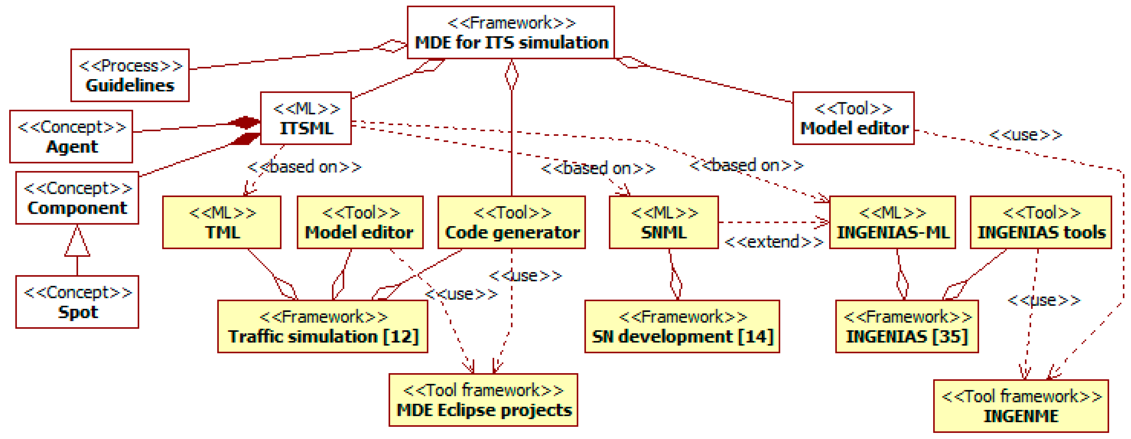
3. The MDE Framework for ITS Simulation

The framework for the development of ITS simulations comprehends the following elements: a ML (see Section 3.1), and guidelines to apply it with a model editor and a code generator (see Section 3.2).

3.1. Modeling Language

The ITSML is organized around the main concepts that appear in this kind of system and its context (see Figure 2). There are persons who interact with vehicles and an external environment, which is composed of things. All these elements are places that can contain multiple spots. A spot is an element that can be observed and/or where containers can be located. Containers are computational nodes, linked by communication channels. In them, software managers control the deployed sensors and actuators. All the previous concepts share some features (e.g., they are modeled with a state and an access interface with methods, and generate events). A common abstract super-concept named component gathers these features.
That conceptual basis is the result of integrating and extending multiple researches related to the domain. The ML follows an ABM approach [8], so it makes of agents, and their interactions among them and with external objects, the core of modeling. This perspective is common to several MLs that provide concepts for the ITSML. The TML [12] is the main one, given the close relationship between the domains of traffic and ITS simulations. The INGENIAS-ML [14] offers a rich set of primitives for ABM and basic extension mechanisms of limited inheritance and composition. It is also the foundation of the SNML [13], which models concepts of devices and their controllers in SNs.
Figure 2. Main concepts (in italics) of the ITS Modeling Language (ITSML) in context.
Sensors 15 14116 g002
The ITSML specifies that conceptual framework using a metamodel. Working with metamodels allows reusing parts of the other MLs. For instance, it supports introducing and modifying concepts and relationships as specializations of those present in the different base metamodels. There are also extensions that mechanisms in the base MLs do not support, but those of metamodels do. For instance, the ITSML has to allow defining instances of arbitrary types in its models.
The meta-modeling language used for the ITSML is the implementation of GOPRR [21] in the INGENME framework [15]. In next diagrams of this section, nodes and relationships, respectively, represent meta-entities and meta-relationships. The ends of these meta-relationships are the meta-roles. Meta-properties appear as attributes or adornments of the previous elements. Examples of these are the numbers in the meta-roles that are cardinality indications. Meta-relationships with triangles represent inheritance, and those with diamonds aggregation, with filled diamonds representing composition and hollow diamonds mere aggregation. This notation is similar to that of UML [18]. As the ITS metamodel integrates concepts from different metamodels, these have been located in packages. Names of concepts and relationships from other metamodels appear qualified with the name of its package, i.e., traffic [12], SN [13], or INGENIAS [14].
The rest of the section discusses in detail the concepts for ITSs in the metamodel. It starts with the general component (see Section 3.1.1). Then, it focuses on the places where sensors and actuators can be deployed and with which they interact (see Section 3.1.2). Managers control these resources to provide services to persons (see Section 3.1.3) moving in an environment (see Section 3.1.4). There are also some general mechanisms applicable to all these concepts (see Section 3.1.5).

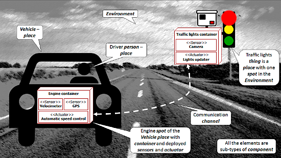
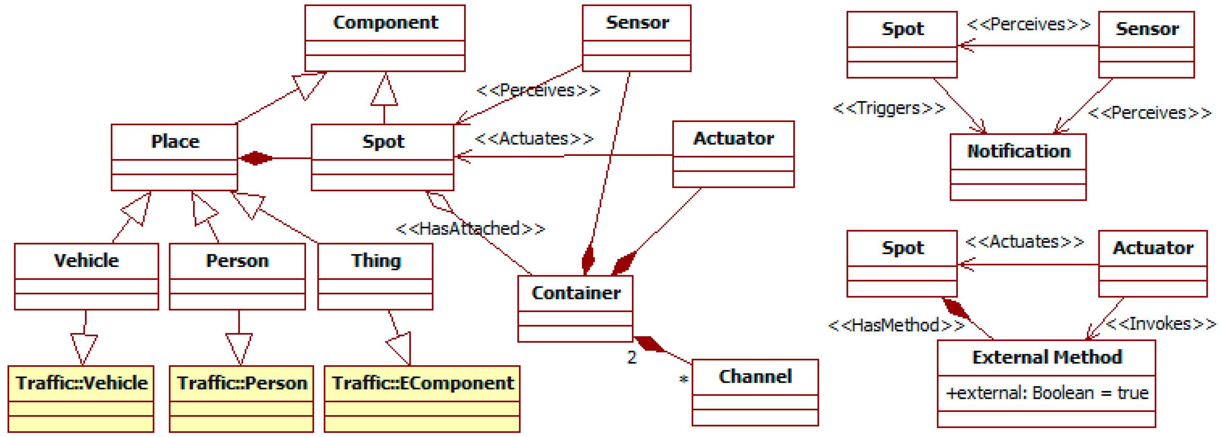
3.1.1. The Component Entity

Figure 3 is focused on the component, which is the base concept in most of the inheritance hierarchies of the ITS metamodel. The SN device and the constituents of the traffic person (with the exception of the mental entities goal and knowledge), vehicle, and environment, become components. Components have an internal state and an interface composed of methods. Methods can be external (when they can be invoked from outside their components), or internal otherwise.
Figure 3. Partial ITS metamodel. Component related elements.
Sensors 15 14116 g003
The state and methods are characterized in terms of information. Pieces of information can be of three types: facts make up the internal state; events are information that appear in components but they do not explicitly produce, and that can be used internally or externally; notifications are information produced for external use. Methods output both facts and notifications, but events come from non-specified parts of components. Besides their results, methods are defined by the parameters they need and the conditions that enable them, which can involve any kind of information. Components can be connected in pipelines using the information their methods produce and consume.
The metamodel defines two convenience meta-relationships for methods and their related information: triggers and perceives. The first one relates a component to a notification that one of its methods generates. The second one links a component to any information that is input to one of its methods. These meta-relationships allow focusing on the considered information and omitting the particular methods involved.

3.1.2. Place and Device Related Entities

An ITS needs to gather information from its surroundings and act on them. Figure 4 shows the high-level structure of this context. It is abstracted as a set of places that contain multiple spots. These spots are the components that can be actually monitored and modified, and where devices can be placed. Following the DVE model adopted by the TML (see Section 2.2), the participants in the traffic phenomena (i.e., persons, their vehicles, and the things in the external environment) are places. Their components according to the TML become spots.
Figure 4. Partial ITS metamodel. Place and Device related elements.
Sensors 15 14116 g004
Following the SNML (see Section 2.3), devices are responsible of sensing and acting in the ITS surroundings. The metamodel incorporates the device-related concepts from SNs as components. A container is the computational resource physically attached to a spot. Communication channels link them. A container runs multiple devices (i.e., sensors, actuators, and utilities). Both sensors and actuators can invoke consult methods of spots. Sensors can also perceive their notifications, and actuators invoke their external modification methods. Utilities are pure software components without access to the surroundings.
Sensors and actuators are thus related to two spots, which can be (or not) different: the one to which their container is attached (i.e., HasAttached meta-relationship); and the one with which they interact. For instance, a place vehicle has a spot for a container with a thermometer sensor that measures the air temperature, being that air a spot in the place weather conditions of the environment. The perceives and actuates meta-relationships are convenience meta-relationships for these interactions. They link sensors and actuators with the spots they manipulate without considering the involved methods.
The control of devices can be modeled in their methods or using manager agents. The activation of a method happens when its inputs (e.g., external notifications and internal events or facts) and the internal state of its device meet some conditions. As a consequence, it generates new information, either internal to the device (as facts) or external for other components (as notifications). For instance, a timer sensor in a traffic light has a method activated by a time-consumed event. When this happens, this method produces a change notification for the actuator in charge of changing lights, which processes it with another method. This method changes to a target light that depends on a fact that represents the current light, and which is part of the internal state of that actuator. On the other hand, manager agents (see more on them in Section 3.1.3) control devices when complex algorithms are needed (as they have a rich model for decision-making) or there is communication among containers (which is one of the specific responsibilities of agents).

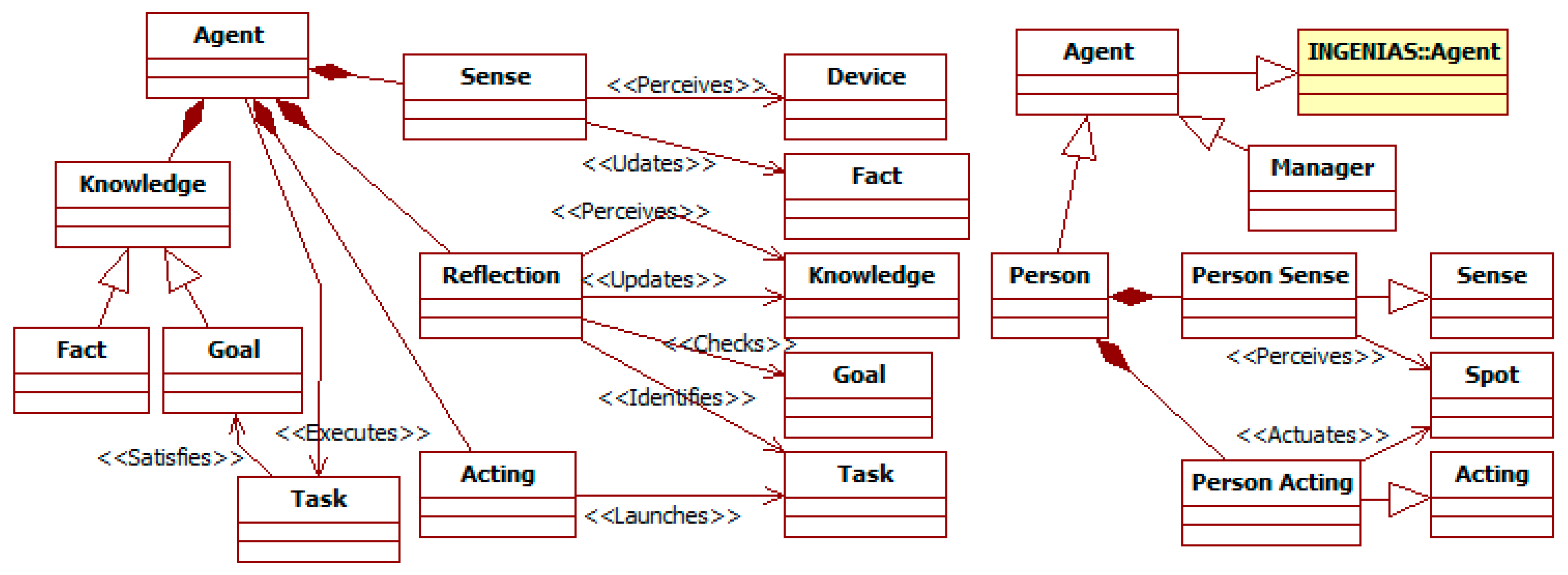
3.1.3. The Person and Manager Entities

The ITS metamodel models with agents complex intentional and social components. These include persons and managers that control devices (see Figure 5). The specification of agents includes the information they have, their goals and capabilities, and the process to manage the previous elements.
Figure 5. Partial ITS metamodel. Person and Manager related elements.
Sensors 15 14116 g005
Knowledge specifies the internal state. It includes facts (i.e., any statement about the world) and goals (i.e., states of the world that an agent wants to keep or to achieve).
Tasks are the high-level actions of agents. They are implemented using methods or other tasks. When using methods, a task is eligible for execution depending on the condition of the method. In this case, the task can change the agent’s knowledge, use devices, or act on the environment through notifications. Communication among agents is modeled as a particular use of notifications. The alternative to define the execution of a task is as a workflow of interconnected tasks to set up complex activities. These workflows follow the INGENIAS-ML [14].
Agents work in a perceive–reflect–act cycle that defines its dynamic behavior. This cycle is modeled with three types of components (i.e., sense, reflection, and acting) that operate over their own and their agent internal state. The sense meta-class models perception as an interaction with observed devices that adds or modifies facts in the state of the agent or the sense. The instances of the reflection meta-class are responsible of the reflection stage. They analyze available knowledge (both facts and goals), and produce new one or modify the existing. Then, they check non-satisfied goals, and identify the tasks related to them and suitable for execution in the current context. Finally, the acting meta-class represents the actual execution of one of the executable tasks.
The agent concept is suitable to represent directly control managers. For persons involved in traffic, there are some modifications. A person has specific person sense and person acting components that allow interacting directly with spots without the need of intermediate devices.
The previous definitions allow aligning concepts from the ITSML with those of its base languages. The ITSML agent, fact, and goal are sub-types of the INGENIAS-ML meta-classes agent, frame fact, and goal. Both the TML knowledge and profile are modeled as ITSML knowledge, and the TML goal is a super-type of the ITSML goal. The person sub-type of agent is also a subtype of the TML person.

3.1.4. The Environment Entity

Regarding the environment, it represents the elements participating in traffic that are not people, their vehicles, or the ITS components (e.g., devices and their managers). Examples of its elements are the roads, the traffic signals, the weather conditions, or obstacles. It is an extension of the TML environment (see Figure 6). It is modeled as an aggregation of things, which are located over a map.
Figure 6. Partial ITS metamodel. Environment related elements.
Sensors 15 14116 g006
The map represents the distribution of the physical space. It is a kind of graph composed by a set of section, each one linking two junctions (at least one) and having a given length. This length can be measured in different units, e.g., kilometers or number of vehicle along it. A section is a set of lanes that can be direct (from the origin to the destination junction) or reverse (the other way). A lane has an occupants list of references to the vehicles or persons in it ordered according to their position.
The other elements of the environment (the equivalent of the TML EComponent) are things. They can be placed in specific map locations, but also being considered global for the environment, e.g., the weather conditions or the sun position.
Vehicles and persons, being places, can have a location. In the case of instances of vehicle, this is mandatory. Persons can have a location, when they are pedestrians, or being attached to a vehicle.

3.1.5. General Features

The ITS metamodel also includes general instantiation, inheritance, and association mechanisms. For each meta-class of name name, there is another meta-class of name Iname that represents its instances at the model level. An instance of the later can be linked to an instance of the former with an instance of the meta-relationship instanceOf. For example, there is a meta-class IPerson linked by a meta-relationship instanceOf to the meta-class Person, so in a model, a specific driver IPerson can be defined as an instance of a specific type of Person. The inheritance mechanism extends those available in the traffic, SN, and INGENIAS MLs. It can be applied to most of concepts in the ITS metamodel, with the semantics that the sub-concept inheriting from the super-concept has all its features, but it can extend or constrain them with additional elements. Default constraints establish that an animated concept (i.e., an instance of the meta-class person) cannot inherit from a non-animated concept (i.e., an instance of a meta-class that is not person), and vice versa. Regarding association, there is a general meta-relationship relatedTo between instances of component. It has a stereotype property to establish arbitrary types of it.

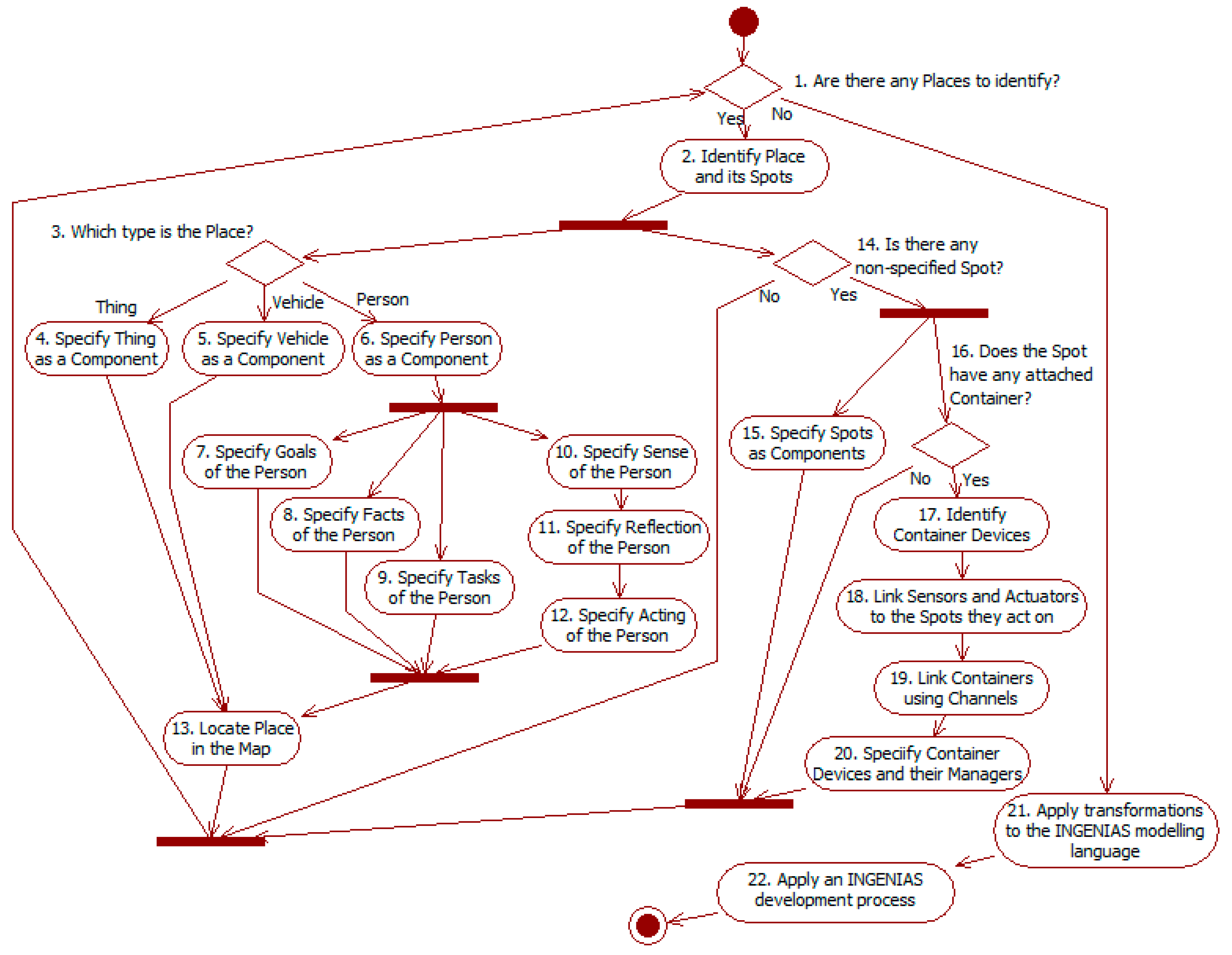
3.2. Development Guidelines and Tools

Figure 7 shows the development guideline for the framework. The process has two different stages. The first one (see nodes 1–20) is specific of this work and focused on modeling with the ITSML. The definition of its metamodel (see Section 3.1) provides hints to identify the different concepts. The results of this stage are models that provide an abstract representation of the ITS and its environment. They are independent of specific target simulation platforms. The second stage takes these models as input and runs transformations to get models with the INGENIAS-ML (see activity 21), and then applies an INGENIAS development processes [27,28] to get the simulation code (see activity 22).
Figure 7. Activity diagram of the development process with the ITSML. Concepts starting with uppercase belong to this ML.
Sensors 15 14116 g007
The process starts identifying places in decision 1. These establish the context of the system and the elements over which the ITS must work. If there is any place, activity 2 assigns it a name and identifies its spots. Next activities in this path specify the place as a component (starting with decision 3) and its spots (see decision 14). If there are not more places to identify, the abstract modeling of the ITS has finished, and the process starts the INGENIAS development (see activities 21 and 22).
The description of a place depends on its type (see decision 3): thing, vehicle, or person. All of them have to be specified as components (see activities 4–6). This specification indicates the information available from these elements, and the means to interact directly with them. Instances of person should not usually include any external method to modify its internal knowledge, as it would violate their autonomy according to the agent paradigm. Other of their features can be modified from the environment, for instance to reflect that they have suffered some injury. If needed, these places must also be located in the environment map (see activity 13), which also implies specifying this.
The specification of a person also comprehends its behavioral cycle. This is specified in terms of its sense (see activity 10), reflection (see activity 11), and acting (see activity 12) components. Sense instances use their methods to get notifications from external sources (i.e., spots and devices), and include it as facts that are part of the internal state of the person. Reflection instances model several activities: generation of new derived knowledge from that already available; checking goal satisfaction according to the current internal state; selection of potential tasks to execute according to the state of goals and other knowledge. Acting instances represent the actual execution of tasks. Activity 7 is used to specify those goals, activity 8 the facts, and activity 9 the tasks. These elements are linked among them: tasks are potentially able to satisfy some goals; goals are satisfied according to conditions specified in terms of knowledge; and tasks are eligible depending on the state of associated goals.
After specifying a place, the process continues with its spots. These spots are elements where devices can be located, or that devices can observe and act on. The specification of spots starts identifying them (see decision 14). Every spot must be defined as a component to determine its related information and methods (see activity 15). Spots are also the elements that can have attached containers (see decision 16). Activity 17 identifies the containers attached to a spot and the devices running in it. Containers are connected through the channels identified in activity 19. Among devices, sensors observe spots and actuators act on them. These spots can be or not the same to which their containers are attached. Activity 18 links sensors and actuators to their target spot. Finally, activity 20 specifies the container devices as components and their managers as agents, if they exist. Although not included in the figure, the specification of managers should follow a similar workflow to that of person (see activities 6–12), as both entities are sub-types of agent.
Activities 21 and 22 correspond to the transition and the development with an INGENIAS process [27,28]. The first activity develops, if not available, and runs an automated transformation with input ITSML specifications and output INGENIAS-ML models. Then it follows an INGENIAS development process to generate the simulation source code. The main issue here has to deal with code generation. It relies on platform-specific templates (see Section 2.3), which must be available from other projects or need to be developed from scratch.
This approach is in line with MDA [26]. The ITSML models are CIMs and PIMs, and the INGENIAS-ML models are PIMs and PSMs, in both cases depending on their level of abstraction.
Figure 7 shows only a sequential perspective of the process. In fact, its actual application needs to be iterative in its different paths. For instance, in the path from nodes 3 to 13, activities 4–6 can be done in the first iterations to give a high-level description of the system context, while the other activities correspond to a later and more detailed specification. In that path also, when modeling the person tasks (see activity 9), it is possible to find out that their execution requires additional internal methods of person, so activity 6 must be revisited. Moreover, when in activity 18 designers link sensors and actuators to the spots they work on, this can lead to modifications in the definition of those spots (made at some moment in activity 15), or even of their places (starting in decision 3).
The previous process is supported by two main tools. A graphical model editor allows generating model instances compliant with the ITS metamodel. This editor has been developed using the infrastructure of INGENME [15]. A code generator takes as input the metamodel and the model instances to generate the source code of the simulation for a target platform. Researchers only need to provide the code templates for that platform, and give the correspondences between those templates and the concepts of the ITS metamodel. The code generator has been developed for the traffic simulation framework [12]. It replaces here the modules used in INGENIAS, which offer less assistance in this process.

4. Experimentation

This section illustrates the application of the previous framework (see Section 3). It includes a case study (see Section 4.1) and a report on additional experiments (see Section 4.2).

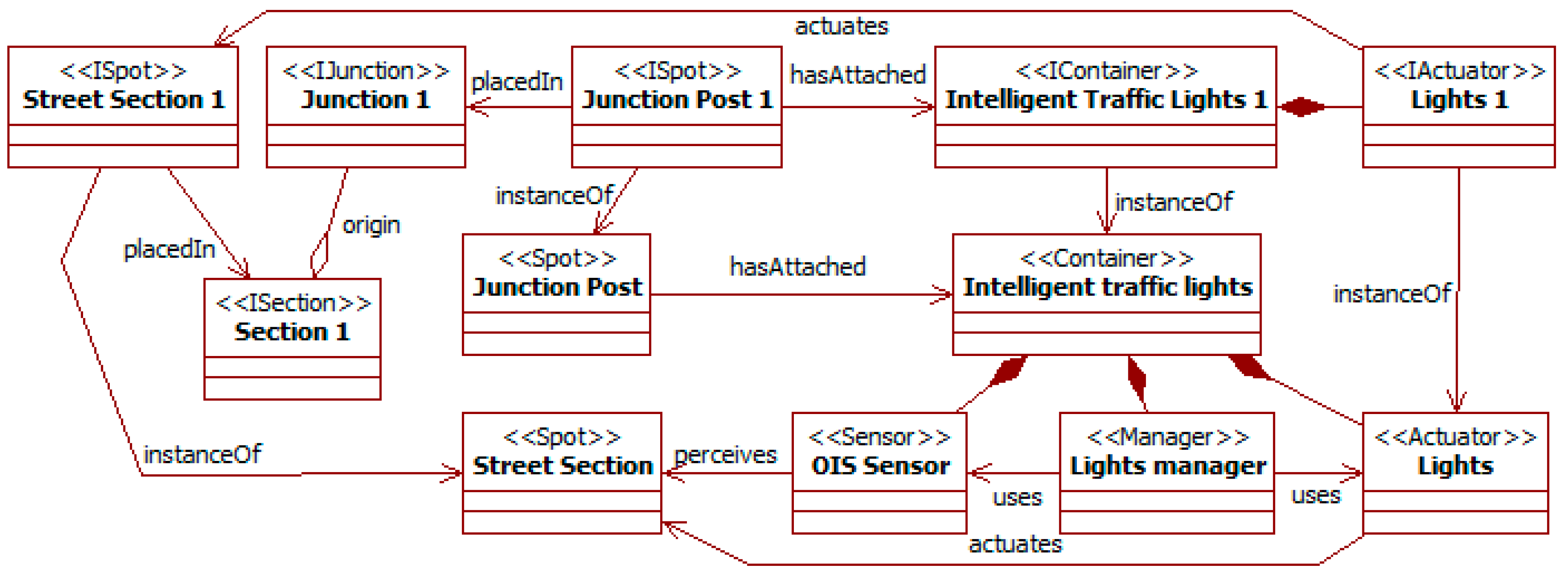
4.1. Case Study: A Control System for Traffic Lights

The availability of affordable sensors and actuators for ITSs has made traffic experts reconsider some of the traditional designs of traffic facilities. In particular, traffic signals can be made more intelligent, in the sense of being aware of the state of traffic in their areas and coordinate with other signals to improve the overall state in wider areas. The use of intelligent traffic lights to control junctions in streets is part of this approach [16]. In that work, the intelligence comes from two main features of these signals. First, they are able to perceive the number of cars in the lanes that join in their junctions. They achieve this using Optical Information System (OIS) sensors. Second, they exchange information to adapt their behavior to the overall traffic state in the area with the goal of maximizing the throughput of cars from it. In order to evaluate the benefits of the use of these intelligent traffic lights over traditional ones, the work in [16] simulates both situations using the SUMO platform and real data of traffic. This case study reproduces this experiment using the ITS simulation framework.
The process starts with the identification of potential places in the problem (see decision 1 and activity 2). According to its definition (see Section 3.1), a place is the component that contains spots, which are the elements where containers can be attached or that sensors can monitor and actuators act upon. The presentation of the problem introduces several of these places. Junctions contain intelligent traffic lights where OIS sensors are located. These sensors perceive lanes from streets.
At this point, the process can continue by specifying those places (starting in decision 3) or the spots and related devices (starting in decision 14) (see Figure 7). As the original work pays particular attention to the system devices, this case study continues in the second path. Figure 8 shows the model instance resulting of it.
Figure 8. Intelligent traffic lights. Container related elements.
Sensors 15 14116 g008
Decision 14 begins identifying the spots of the previous places. The traffic lights are considered as located in the junction posts surveying the main street sections. Both junction posts and street sections are spots, as the former represent where devices are located, and the latter what they survey and affect. Activity 15 specifies these spots as components. In this case, they do not have any specific state or functionality to specify. Only street sections could have it related to the vehicles in them. However, this specification is considered later in the environment map.
The next nodes in the path focus on the devices the simulated ITS uses to perceive and act. The first step in decision 16 is discovering the spots with containers for these devices. In this case, there is only one of such spots: the junction posts.
Activity 17 identifies the devices running in the containers. The intelligent traffic lights are modeled as containers in junction posts. They have as sensors the OIS sensors that allow them perceiving the queues in their lanes (using the street sections); their actuators are their red, green, and yellow lights. Activity 18 links OIS sensors to the street sections spots they watch, and lights to the street sections spots they are pointing at.
The containers of ITSs are not isolated. They set up a complete system thanks to its communications through channels. Activity 19 identifies these channels. The intelligent traffic lights are connected in this way (not shown in the figure) to share the state of the whole area.
Activity 20 models the sensors and actuators of containers as components, and their managers. An OIS sensor has a method to consult the number of vehicles in its lane. A light has a state characterized by its current color, the time remaining in it, and the current default time assigned to each color; its methods allow checking the previous values and changing the periods assigned to each color and which to display. As in the SNML, complex control algorithms are modeled using the managers of devices, which are agents. In [16], traffic lights adapt the time assigned to each color according to the information from their sensors and from traffic lights in the other junctions. For this problem, a lights manager orchestrates work in each intelligent traffic lights container. It obtains information from its OIS sensors and sends it to the managers in the other junctions using the channels. It also receives from the channels the updates from the other junction posts. Finally, with all of this information, it updates the lights state.
Figure 8 also shows how to introduce instances of the types identified for a given problem. The instance lights 1 of the class lights runs in the instance intelligent traffic lights 1 of the container, and it governs the traffic of the instance street section 1 of the class street section.
After modeling spots, containers, and their devices, the specification needs to consider the persons and their vehicles, as well as the environment where all these elements interact. This corresponds in the process to the paths for places starting in decision 3 (see Figure 7).
In [16], only vehicles are modeled, as drivers are implicit in their control. Using data from real places, researchers determined the volume of traffic in the different sections of streets and the junction turning percentages. In the ITSML, the vehicle is a passive component, and the decision-making is modeled with the driver person.
Activity 5 models the vehicle component. In this case, it has no state. The environment map models its position (see later activity 13). Its methods should move the car, change the lane, and check its own position, that of other vehicles around it, and the color of the traffic lights in its street section.
The specification of person is more complex. It includes the elements representing its basic knowledge and actions (see activities 6–9), and the perceive–reflect–act cycle (see activities 10–12).
Activity 6 specifies the person as a component, mainly regarding the external methods intended to check its state. Here, no one is needed. Activities 7–9 model its knowledge and capabilities. The goal of the driver is the path to follow in the street. It is characterized by the entry and exit points to the street, and the exit to take at each junction. The agent only needs to know the position of the vehicle to make decisions. This is a fact that directly translates the information provided by the vehicle methods. The tasks of the agent are those to check the environment and manoeuver the vehicle. In the first group are checking junction (to know when to turn and in which direction), checking position (to know if there is a vehicle in a given position), and checking lights (to know if the vehicle can go into the junction given the traffic lights). The second group includes moving forward, turn (left or right and the number of exit), and stop the vehicle.
Activities 10–12 use the previous elements to represent the acting cycle of the driver person. Activity 10 models sense. It only needs to perceive the vehicle spot to assert the facts regarding its current position, whether the surrounding positions are busy, and the color of traffic lights. Activity 11 models reflection. It compares the current position with the next turn. If the vehicle has not reached the turning position and lights allow it, it chooses the task to move forward; if it has reached the position, it chooses to turn when the target position is available; in other case, it waits. Activity 12 models acting, that translates one of the potential tasks for execution to person and vehicle methods.
The last places to describe are things in the environment. Activity 4 specifies them as components. The already mentioned junctions and streets are things. Here, their specifications are empty because these places are only containers for spots.
The final step in this modeling is activity 13, where places are located in the environment map. In [16], there are three junctions across a street, and each junction connects two sections of the street and a transversal section from other streets. The thing street is located over the three junctions and two sections. These elements and the transversal sections have direct correspondences in the ITSML as parts of the map. The model also needs to specify the number and orientation of lanes in each section.
Figure 9 shows the model resulting of these activities, omitting lanes of sections and the links between the street and junctions. All the elements appear as instances (i.e., stereotypes Iname) of classes (i.e., stereotypes name) that are the direct representation of their meta-classes (i.e., name of the meta-class). For instance, the metamodel (see Section 3.1) includes a section meta-class. Section 1–2 and section transversal 1–3 are instances of a class section that is a direct instance (without any modification) of the meta-class section. The reason of this modeling is that specifying these instances only needs using existing elements, and not adding new state, methods, or relationships.
When all the previous modeling has finished, activity 21 runs the transformations to create INGENIAS-ML models from these ITSML specifications. Their correspondences follow the inheritance relationships of meta-classes in the ITSML to those of the INGENIAS-ML when they exist. For instance, the ITSML components in models become INGENIAS-ML environment applications, as component is a sub-meta-class of environment application (see Figure 3). In the case of multiple inheritances, the base target meta-class is that with the closer semantics. For instance, the ITSML person inherits from the INGENIAS-ML agent, and through place and component also of the INGENIAS-ML environment application (see Figure 3 and Figure 4). However, its meaning is closer to the INGENIAS-ML agent. Thus, the transformation generates for a person an INGENIAS-ML agent, though it also adds additional elements corresponding to it being also a place.
Figure 9. Intelligent traffic lights. Environment related elements.
Sensors 15 14116 g009
Finally, activity 22 follows an INGENIAS process [27,28] to refine those INGENIAS models and generate the source code for the simulation in SUMO [16]. In this case, INGENIAS models mainly add the description of the interactions among manager agents regarding the exchange of information from their intelligent traffic lights. SUMO specifies most of the components of its simulations using XML files. The main mappings with the original concepts from the ITSML are the following. The map of the environment is represented in SUMO as a network. Its nodes and edges are, respectively, ITSML junctions and lanes. The SUMO vehicle merges the ITSML vehicle and driver person. SUMO does not allow controlling the movements of its vehicles, as it provides only a limited set of implementations for them. Nevertheless, the path vehicles have to follow can be specified, and SUMO controls that traffic signals are observed. Regarding traffic lights, SUMO supports actuated traffic lights for the experiments described in [16]. They can change the time showing each color according to the number of vehicles in the edges they control.

4.2. Discussion

The proposed framework has been tested in several experiments with the purpose of assessing its components. These experiments considered different contexts in order to evaluate its adaptability to multiple needs regarding simulation. In particular, the ITSML has been used to specify different models for people and types of ITS, and the process and tools also for several target platforms.
Regarding decision-making (see Section 3.1.3), there has been work with the goal-model of INGENIAS [14] and the reactive model for drivers in [32]. Compared to the ITSML, INGENIAS offers additional primitives to model goals with the distinction between hard (with quantitative evaluations) and soft (with qualitative evaluations) goals, and different relationships (e.g., affects, contributes positively, satisfies, and AND and OR compositions). The work in [32] offers an alternative perceive–reflect–act cycle. Its agents consider timed data, and combine for reflection a reactive model and a short-time planner.
The concepts in the previous models are specializations of types already available in the ITSML. For instance, hard and soft goals [14] are sub-types of goal, and the short-time planner [32] of reflection. Relationships can be represented using instances of the relatedTo meta-relationship. Nevertheless, this is a limited approach, as it does not allow introducing constraints. For instance, INGENIAS relations between goals can be modeled, but not constrained with graphical primitives to link only goals.
There is also work with other types of ITS. Smart roads [33] are ITS which SNs are mainly deployed on roads. Their models with the ITSML use specializations of concepts related to devices and managers (see Section 3.1.2) and the environment (see Section 3.1.4). In [33], there are eye cats (a type of spot) deployed on road borders (which are things). The eye cats hold magnetic trackers (as sensors) that perceive vehicles passing near them. Manager agents represent the control of these sensors and their communications.
The framework has also been tested with different target simulation platforms. Besides the already mentioned SUMO [16], it has also been tested with MATSim [34] and the platform for traffic simulation in [35]. MATSim mainly defines vehicle movement using paths and additional parameters that influence it, as SUMO does. Thus, the approach described for SUMO in the case study (see Section 4.1) is applicable with minor changes to MATSim. MATSim can also be extended with additional behavioral modules, as the platform in [35]. The latter distinguishes between vehicles and drivers, and supports complex agent-based models for people. Drivers have a basic behavior of path following that can incorporate maneuvers and general constraints on movement as goals. With the ITSML, those constraints are also modeled as goals, linked to tasks that represent maneuvers. Tasks are related to conditions that represent when those maneuvers can be considered for execution. In all the cases, the first tests with these platforms require developing specific code snippets to connect already available code (that for abstract models) with the platform. This also happened in the experiment reported in the case study. These new fragments could later be reused, or adapted with less effort, when experiments continued, and integrated in the code generation tasks.
In these cases, the process points out the ITSML primitives suitable to model the concepts from those models and platforms. However, two aspects remain little described, the choice of relationships and the use of inheritance. Relationships are deduced from the context provided by concepts. The process focuses on the latter, and these determine the allowed relationships. There are no indications on how to choose when several relationships are available beyond their description in the ITSML. There are also sometimes difficulties to design inheritance hierarchies, particularly to establish what concepts must be extended.

5. Qualitative Comparative Analysis

This work is related to two main aspects of research in ITSs. It deals with the relevant concepts to model this kind of system, and the approaches followed in their analysis, development, and simulation.
ITSs cover a wide variety of needs [3,5,6,36], e.g., reduction of traffic congestions, toll collection, parking, collision avoidance, or emergency response. However, their architectures and perspectives on the environment present a similar structure. There is a world external to the system that includes, for instance, environmental conditions (e.g., weather, sun position, or daytime) [33,37], roads [33,38], vehicles [37,39], or pedestrians [39]. ITSs include devices (sensors and actuators), which are their “interface” to interact with that environment [6,40]. Using them, ITSs provide their services. These services may require computational resources beyond devices, e.g., servers to store information or allow users to monitor the system and the environment.
The previous facets can be effectively integrated using a view of these elements based on external interfaces able to manipulate their state. In most cases, their inner structure and behavior can be disregarded. For instance, with the exception of works focused on device control (e.g., [39,41]), most of research adopts a high-level view of devices, focused on the data they gather and the services they provide (e.g., [33,38,40]). Such perspective is also applied in the models of environment elements when needed. The only exception is the map of the environment, which is modeled with some kind of graph, e.g., when working with location information from the Global Positioning System (GPS) [38].
The point of view of simulation is slightly different. It needs to integrate concepts to model the objects in the external reality and their behavior, so it can represent their influence in sensors and actuators [42]. For instance, drivers’ behavior is not only an aspect to observe, but also to manipulate in order to test the person and system functioning in multiple circumstances.
Regarding vehicles, simulations need at least to establish partially their path (i.e., origin and destination, and sometimes intermediate points). The specific way in which a vehicle meets this objective offers variations. There are works that consider an strict adherence to the path (i.e., the path constitutes the precise movement instructions) [16], some partially random movements around it (e.g., to decide how to move between two points of the target path) [43], path calculation algorithms (e.g., shortest path under different cost functions [16,34,43]), and specific maneuvers (e.g., car following, lane change, or turns) [43,44] to follow it. Nevertheless, microscopic models (where vehicles are individually modeled) such as [16,34,43,44], could allow modeling more complex and flexible behaviors by replacing the default ones. However, this is not documented in the reviewed works, and it would probably require modifying the code of the considered simulation platforms.
Most of works discard the explicit modeling of drivers, and only consider vehicle control [16,43]. Some references [43,44] include pedestrians, but only as moving objects, similar in their description to vehicles. General traffic studies are more prone to consider these issues. Their models can specify the mental state and features of people, for instance regarding their goals and ability [30], their decision-making [45], or their roles in traffic (i.e., pedestrians, drivers, and passengers) [12].
Both in the case of vehicles and people, researchers lack of support to extend the provided default implementations. For instance, there is little documentation, libraries, base classes for inheritance, or schedulers for multiple tasks, in the platforms to help coding these modifications.
Our ITSML addresses these issues at several levels. It provides an extensible metamodel able to accommodate the different previous modeling approaches. The specification of environment elements and vehicles as objects with state and method interfaces is achieved with components. People and vehicle movements are modeled through the specification of persons. The case study (see Section 4.1) already includes an example of path following with maneuvers. The adoption of agents to represent persons goes further and allows describing the wide range of alternative models for people in traffic studies, from reactive to deliberative ones. Moreover, managers of devices are also modeled as agents, which facilitates representing complex distributed algorithms for ITSs including information management (e.g., goals, facts, probabilities, or uncertainty). Many issues usually considered in code are promoted to models, so researchers can define their requirements using MLs. Then, standard MDE development methodologies translate models to source code. When this translation is done, it provides documentation and reusable artifacts (i.e., models and transformations) for similar implementations. Thus, it provides the basis to build improved support resources for these tasks.
The already discussed conceptual frameworks are intended to be the basis for the analysis of ITSs. They focus on the external interface of these systems (i.e., behavior perceived by users), the environment, and their mutual influences. However, those references do not consider the internal organization of such systems, beyond, for instance, coding constraints imposed by simulation platforms. There are specific works focused on the architecture of ITSs. They usually present abstract models and hints for their implementation (e.g., [33,37]). Other works address low-level aspects of these systems, e.g., control or coordination mechanisms. They are usually focused on specific aspects, e.g., issues of computer vision in [41]. When dealing with such details, the use of simulations is common [7,16,42].
Works such as SUMO [16], DEUS [43], MATSim [34], the Tokyo Virtual Living Lab [44], the test platform in [35], or those reviewed in [42], are traffic simulation platforms. They include libraries to develop and run simulations, and sometimes user interfaces to specify them. Although there are descriptions of their underlying abstract theoretical models, they are black-boxes. A complete understanding of their functioning can require examining their source code when it is available. Literature has already pointed out this issue as one of the main limitations in the use of simulations for research, as it makes difficult guaranteeing the alignment between abstract models and simulations [8].
In most cases, works do not describe the development process followed. There are not explicit guidelines to reproduce modeling, design, or coding. This lack of documentation hampers validation and sharing experiences on development. Moreover, works focus on solving specific issues at a given level of abstraction, e.g., abstract model, architecture, or control of devices. They do not identify ways to integrate that research with complementary works to offer a complete solution to develop ITSs.
The current work adopts MDE to support these tasks. It provides an approach with several abstraction levels intended for different backgrounds. Researchers on ITSs work with the ITSML at the levels of CIM and PIM. Designers of simulations and programmers work mainly with the INGENIAS-ML at the levels of PIM and PSM. In both cases, experts integrate and refine models adding new information and using transformations. For the first group of tasks, this work offers modeling guidelines; for the second, INGENIAS provides a complete development methodology. The overall approach facilitates the explicit representation of all the information involved in the transition from the abstract models to code, which facilitates validation and reutilization.

6. Conclusions

This paper has presented a MDE approach for the analysis through simulations of ITSs. The complexity of these systems and the environments where they act implies high development costs. This kind of issues has been addressed in other domains through simulation. However, its application demands means to facilitate the transition from the abstract models of systems to the simulation, and its validation. Usually, researchers make these tasks manually, what is an additional source of mistakes. Adopting MDE approaches, researchers explicitly describe these steps with models and transformations. This facilitates their examination, and therefore validation and testing.
The proposed framework comprehends a ML, guidelines, and tools to develop ITS specifications and simulations. It is intended for the complete development process, focusing effort on the high-level design. Its definition reuses previous research in aspects related to ITSs. The ITSML is built over the TML [12] and the SNML [13], extending them with ITS-specific concepts. All these languages adopt the agent paradigm [11], which facilitates integrating the different perspectives.
The ITSML conceives all the elements in this domain as components, which are characterized by their state and a method-based interface. Flows of control and information among components use these methods. ITSs interact with their external environment using a layer of sensors and actuators, which are also components. Complex algorithms are modeled with agents. These include components for perception, reflection, and acting that manipulate information and goals.
For control activities, sensors perceive events from the environment, which they transform in internal facts. Their methods generate notifications from those facts that are communicated to other components, including manager agents. These use available information to check goals and decide what tasks to attempt. The execution of tasks invokes methods, which can generate new notifications. Some of these notifications trigger the execution of actuator methods, which act on the environment.
The concepts related to traffic are organized following an adapted DVE [30] model according to the structure of the TML [12]. They include common primitives such as person, vehicle, and thing (i.e., environment element). Here, they are linked to the group of concepts corresponding to devices and their manager controllers extracted from the SNML. This last group models the interface between ITSs and their external environment.
The ITSML also provides mechanisms of inheritance and instantiation of classes in models. The first one allows flexible extensions of the ML without modifying its metamodel. The second one supports the complete definition of the components of the simulation at the model level. In this way, only algorithms need to be specified with code.
The development guidelines, along with the definition of concepts in the metamodel, help designers to build their specifications. They provide a step-by-step process to look for relevant elements in problems, and translate them to modeling primitives. The low-level design and coding follow INGENIAS [14], an existing MDE methodology for MASs. The use of agent concepts in the ITSML and the INGENIAS-ML facilitates the transition between both stages using automated transformations.
The final elements of the framework are the support tools. A model editor based on INGENME [15] supports specifying models compliant with the ITS metamodel. The code generator of the traffic framework [12] is used in the later stages of the INGENIAS process. It replaces the usual INGENIAS tools, because it provides more guidance to work jointly with models and code templates.
This framework has been used in several experiments. The case study developed a simulation of an ITS with intelligent traffic lights for the simulation platform SUMO [16]. The models specified most of the intended simulation. Only algorithms (e.g., using thresholds and timing to change the color of traffic lights, or the methods to interact with SUMO) need to be coded. As most of this code appears in templates that can be reused in code generation for different model elements, the actual coding effort is highly reduced. Changes in the simulation would only affect the model if they add new instances of available classes of entity or relationship. If new classes appear, only the templates for them need to be added before regenerating the simulation. Templates could be reused from other simulation projects. Similar findings appear in the other reported experiments, which considered simulations with extended models of decision-making, other types of ITS, and several simulation platforms.
This framework is still ongoing work with several open issues, some of them already pointed out in experiments in Section 4. First, the metamodel needs to be enriched with additional primitives. Primitives to represent tasks ordering or preferences are not available. Also, the specification of vehicle parts and their actions is not possible, for instance to represent the angle and acceleration of a vehicle turn in a junction as done in [44]. Second, certain constraints on the model, for example in the number of instances of a class, inheritance relationships, or values of attributes, cannot be expressed. The use of a constraint language such as the Object Constraint Language (OCL) [46] would reduce here the need to resort to code. Third, the development guidelines need to be extended. Now, they indicate a possible ordering of steps and leave for the metamodel definition the indications on how to identify the different modeling concepts. The identification hints should also be transferred to the process specification. Finally, additional experimentation is required to validate the framework. Current experiments are limited in number, the types of ITS modeled, and the considered simulation infrastructures.

Acknowledgments

This work has been done in the context of the projects “Social Ambient Assisting Living—Methods (SociAAL)” (TIN2011-28335-C02-01) supported by the Spanish Ministry for Economy and Competitiveness. Also, we acknowledge support from the “Red Científico-Tecnológica en Ciencias de los Servicios” (TIN2011-15497-E) and the “Programa de Creación y Consolidación de Grupos de Investigación” (UCM-BSCH GR35/10-A).

Author Contributions

Alberto Fernández-Isabel developed the framework for the MDE of ITS simulations, and implemented the case study. Rubén Fuentes-Fernández adapted the INGENIAS and INGENME infrastructure for the framework. All the authors contributed equally to writing the paper.

Conflicts of Interest

The authors declare no conflict of interest.

References

  1. Chourabi, H.; Nam, T.; Walker, S.; Gil-Garcia, J.R.; Mellouli, S.; Nahon, K.; Pardo, T.A.; Scholl, H.J. Understanding Smart Cities: An Integrative Framework. In Proceedings of the 45th Annual Hawaii International Conference on System Sciences (HICSS 2012), Maui, HI, USA, 4–7 January 2012; Sprague, R.H., Jr., Ed.; IEEE: Washington, DC, USA, 2012; pp. 2289–2297. [Google Scholar]
  2. Harrison, C.; Donnelly, I.A. A Theory of Smart Cities. In Proceedings of the 55th Annual Meeting of the International Society for the Systems Sciences (ISSS 2011), Hull, UK, 17–22 July 2011; pp. 1–15.
  3. Tewolde, G.S. Sensor and Network Technology for Intelligent Transportation Systems. In 2012 IEEE International Conference on Electro/Information Technology (EIT 2012), Indianapolis, IN, USA, 6–8 May 2012; IEEE: Washington, DC, USA, 2012; pp. 1–7. [Google Scholar]
  4. The European Parliament and the Council of the European Union. Directive 2010/40/EU of the European Parliament and of the Council of 7 July 2010, on the Framework for the Deployment of Intelligent Transport Systems in the Field of Road Transport and for Interfaces with Other Modes of Transport. Available online: http://eur-lex.europa.eu/ (accessed on 15 March 2015).
  5. Figueiredo, L.; Jesus, I.; Machado, J.A.T.; Ferreira, J.; de Carvalho, J.L.M. Towards the Development of Intelligent Transportation Systems. In Proceedings of the 2001 IEEE Intelligent Transportation Systems Conference (ITSC 2001), Oakland, CA, USA, 25–29 August 2001; IEEE: Washington, DC, USA, 2001; pp. 1206–1211. [Google Scholar]
  6. Klein, L.A. Sensor Technologies and Data Requirements for ITS; Artech House Publishers: Norwood, MA, USA, 2001. [Google Scholar]
  7. Pursula, M. Simulation of Traffic Systems—An Overview. J. Geogr. Inf. Decis. Anal. 1999, 3, 1–8. [Google Scholar]
  8. Axtell, R.L.; Epstein, J.M. Agent-based modeling: Understanding our creations. Bull. St. Inst. 1994, 9, 28–32. [Google Scholar]
  9. Bézivin, J. Model Driven Engineering: An Emerging Technical Space. In Generative and Transformational Techniques in Software Engineering; Lecture Notes in Computer Science; Lämmel, R., Saraiva, J., Visser, J., Eds.; Springer: Heidelberg, Germany, 2006; Volume 4143, pp. 36–64. [Google Scholar]
  10. Fuentes-Fernández, R.; Hassan, S.; Pavón, J.; Galán, J.M.; López-Paredes, A. Metamodels for role-driven agent-based modelling. Comput. Math. Organ. Theory 2012, 18, 91–112. [Google Scholar] [CrossRef]
  11. Müller, J.P.; Pischel, M.; Thiel, M. Modeling Reactive Behaviour in Vertically Layered Agent Architectures. In Intelligent Agents; Lecture Notes in Computer Science; Wooldridge, M.J., Jennings, N.R., Eds.; Springer: Heidelberg, Germany, 1995; Volume 890, pp. 261–276. [Google Scholar]
  12. Fernández-Isabel, A.; Fuentes-Fernández, R. A Model-Driven Engineering Process for Agent-Based Traffic Simulations. In Proceedings of the 5th International Conference on Simulation and Modeling Methodologies, Technologies and Applications (SIMULTECH 2015), Colmar, France, 21–23 July 2015; SCITEPRESS: Setúbal, Portugal, 2015; pp. 1–10. [Google Scholar]
  13. Fuentes-Fernández, R.; Guijarro, M.; Pajares, G. A Multi-Agent System Architecture for Sensor Networks. Sensors 2009, 9, 10244–10269. [Google Scholar] [CrossRef] [PubMed]
  14. Pavón, J.; Gómez-Sanz, J.J.; Fuentes, R. The INGENIAS Methodology and Tools. In Agent-Oriented Methodologies; Henderson-Sellers, B., Giorgini, P., Eds.; Idea Group Publishing: Hershey, PA, USA, 2005; Chapter IX; pp. 236–276. [Google Scholar]
  15. Pavón, J.; Gómez-Sanz, J.; Paredes-López, A. The SiCoSSyS approach to SoS engineering. In Proceedings of the 6th International Conference on System of Systems Engineering (SoSE 2011), Albuquerque, NM, USA, 27–30 June 2011; IEEE: Washington, DC, USA, 2011; pp. 179–184. [Google Scholar]
  16. Krajzewicz, D.; Brockfeld, E.; Mikat, J.; Ringel, J.; Rössel, C.; Tuchscheerer, W.; Wagner, P.; Wösler, R. Simulation of modern Traffic Lights Control Systems using the open source Traffic Simulation SUMO. In Proceedings of the 3rd Industrial Simulation Conference (ISC 2005), Berlin, Germany, 9–11 June 2005; Krueger, J., Lisounkin, A., Schreck, G., Eds.; EUROSIS-ETI: Ostend, Belgium, 2005; pp. 299–302. [Google Scholar]
  17. Object Management Group. OMG Meta-Object Facility (MOF) Core Specification, Version 2.4.2; Object Management Group, 2014. Available online: http://www.omg.org/ (accessed on 15 March 2015).
  18. Object Management Group. OMG Unified Modeling Language (OMG UML), Version 2.5; Object Management Group, 2013. Available online: http://www.omg.org/ (accessed on 15 March 2015).
  19. Steinberg, D.; Budinsky, F.; Paternostro, M.; Merks, E. EMF—Eclipse Modeling Framework, 2nd ed.; Addison-Wesley Professional: Boston, MA, USA, 2008. [Google Scholar]
  20. Lopes, D.; Hammoudi, S.; Bézivin, J.; Jouault, F. Mapping Specification in MDA: From Theory to Practice. In Interoperability of Enterprise Software and Applications; Konstantas, D., Bourrières, J.-P., Léonard, M., Boudjlida, N., Eds.; Springer: Heidelberg, Germany, 2006; pp. 253–264. [Google Scholar]
  21. Kelly, S.; Lyytinen, K.; Rossi, M. Metaedit+: A fully configurable multi-user and multi-tool CASE and CAME environment. In Advanced Information Systems Engineering; Lecture Notes in Computer Science; Constantopoulos, P., Mylopoulos, J., Vassiliou, Y., Eds.; Springer: Heidelberg, Germany, 1996; Volume 1080, pp. 1–21. [Google Scholar]
  22. Mens, T.; van Gorp, P. A Taxonomy of Model Transformation. Electron. Notes Theor. Comput. Sci. 2006, 152, 125–142. [Google Scholar] [CrossRef]
  23. Czarnecki, K.; Helsen, S. Feature-Based survey of model transformation approaches. IBM Syst. J. 2006, 45, 621–645. [Google Scholar] [CrossRef]
  24. Eclipse M2T. Eclipse Modeling-M2T-Home. Available online: https://www.eclipse.org/modeling/m2t/ (accessed on 15 March 2015).
  25. Eclipse MMT. Eclipse Model to Model Transformation. Available online: https://www.eclipse.org/mmt/ (accessed on 15 March 2015).
  26. Kleppe, A.G.; Warmer, J.; Bast, B. MDA Explained: The Model Driven Architecture—Practice and Promise; Addison-Wesley: Boston, MA, USA, 2003. [Google Scholar]
  27. Gómez-Rodríguez, A.; Fuentes-Fernández, R.; González-Moreno, J.C.; Rodríguez-Martínez, F.J. INGENIAS with the Unified Development Process. In Handbook on Agent-Oriented Design Processes; Cossentino, M., Hilaire, V., Molesini, A., Seidita, V., Eds.; Springer: Heidelberg, Germany, 2014; pp. 371–405. [Google Scholar]
  28. González-Moreno, J.C.; Gómez-Rodríguez, A.; Fuentes-Fernández, R.; Ramos-Valcárcel, D. INGENIAS-Scrum. In Handbook on Agent-Oriented Design Processes; Cossentino, M., Hilaire, V., Molesini, A., Seidita, V., Eds.; Springer: Heidelberg, Germany, 2014; pp. 219–251. [Google Scholar]
  29. García-Magariño, I.; Fuentes-Fernández, R. A Technique for Defining Metamodel Translations. IEICE Trans. Inf. Syst. 2009, 92, 2043–2052. [Google Scholar] [CrossRef]
  30. Amditis, A.; Pagle, K.; Joshi, S.; Bekiaris, E. Driver-Vehicle-Environment monitoring for on-board driver support systems: Lessons learned from design and implementation. Appl. Ergon. 2010, 41, 225–235. [Google Scholar] [CrossRef] [PubMed]
  31. Rubel, D.; Wren, J.; Clayberg, E. The Eclipse Graphical Editing Framework (GEF); Addison-Wesley Professional: Boston, MA, USA, 2011. [Google Scholar]
  32. Ehlert, P.A.M.; Rothkrantz, L.J.M. Microscopic traffic simulation with reactive driving agents. In Proceedings of the 2001 IEEE Intelligent Transportation Systems Conference (ITSC 2001), Oakland, CA, USA, 25–29 August 2001; IEEE: Washington, DC, USA, 2001; pp. 860–865. [Google Scholar]
  33. Karpiriski, M.; Senart, A.; Cahill, V. Sensor networks for smart roads. In Proceedings of the 4th Annual IEEE International Conference on Pervasive Computing and Communications, Workshops (PerComW 2006), Pissa, Italy, 13–17 March 2006; IEEE: Washington, DC, USA, 2006; p. 310. [Google Scholar]
  34. Transport Systems Planning and Transport Telematics Group (Technische Universität Berlin); Transport Planning Group (Swiss Federal Institute of Technology Zurich); Senozon Company. MATSim, Multi-Agent Transport Simulation; MATSim, 2015. Available online: http://www.matsim.org/ (accessed on 25 May 2015).
  35. Fernández-Isabel, A.; Fuentes-Fernández, R. An Agent-Based Platform for Traffic Simulation. In Soft Computing Models in Industrial and Environmental Applications, 6th International Conference SOCO 2011; Advances in Intelligent and Soft Computing. Corchado, E., Snášel, V., Sedano, J., Hassanien, A.E., Calvo, J.L., Ślȩzak, D., Eds.; Springer: Heidelberg, Germany, 2011; Volume 87, pp. 505–514. [Google Scholar]
  36. Pascale, A.; Nicoli, M.; Deflorio, F.; Dalla Chiara, B.; Spagnolini, U. Wireless sensor networks for traffic management and road safety. IET Intell. Transp. Syst. 2012, 6, 67–77. [Google Scholar] [CrossRef]
  37. Sun, Z.; Bebis, G.; Miller, R. On-Road vehicle detection: A review. IEEE Trans. Pattern Anal. Mach. Intell. 2006, 28, 694–711. [Google Scholar] [PubMed]
  38. Faouzi, N.-E.E.; Leung, H.; Kurian, A. Data fusion in intelligent transportation systems: Progress and challenges—A survey. Inf. Fusion 2011, 12, 4–10. [Google Scholar] [CrossRef]
  39. Gandhi, T.; Trivedi, M.M. Pedestrian protection systems: Issues, survey, and challenges. IEEE Trans. Intell. Transp. Syst. 2007, 8, 413–430. [Google Scholar] [CrossRef]
  40. Hancke, G.P.; de Carvalho e Silva, B.; Hancke, G.P., Jr. The Role of Advanced Sensing in Smart Cities. Sensors 2012, 13, 393–425. [Google Scholar] [CrossRef] [PubMed]
  41. Trivedi, M.M.; Gandhi, T.; McCall, J. Looking-In and looking-out of a vehicle: Computer-Vision-Based enhanced vehicle safety. IEEE Trans. Intell. Transp. Syst. 2007, 8, 108–120. [Google Scholar] [CrossRef]
  42. Kotusevski, G.; Hawick, K.A. A Review of Traffic Simulation Software. Res. Lett. Inf. Math. Sci. 2009, 13, 35–54. [Google Scholar]
  43. Picone, M.; Amoretti, M.; Zanichelli, F. Simulating Smart Cities with DEUS. In Proceedings of the 5th International ICST Conference on Simulation Tools and Techniques (SIMUTOOLS 2012), Desenzano, Italy, 19–23 March 2012; pp. 172–177.
  44. Prendinger, H.; Gajananan, K.; Zaky, A.; Fares, A.; Molenaar, R.; Urbano, D.; van Lint, H.; Gomaa, W. Tokyo Virtual Living Lab: Designing Smart Cities Based on the 3D Internet. IEEE Internet Comput. 2013, 17, 30–38. [Google Scholar] [CrossRef]
  45. Salvucci, D.D.; Boer, E.R.; Liu, A. Toward an Integrated Model of Driver Behavior in Cognitive Architecture. Transp. Res. Rec. J. Transp. Res. Board 2001, 1779, 9–16. [Google Scholar] [CrossRef]
  46. Object Management Group. Object Constraint Language, Version 2.4; Object Management Group, 2014. Available online: http://www.omg.org/ (accessed on 15 March 2015).

