
A Computational Architecture Based on RFID Sensors for Traceability in Smart Cities


Abstract
:1. Introduction
2. Population Track and Trace Issues
2.1. Problem Definition
2.2. Literature Survey

| Work | Main Application | Working Environment | Tag Deployment | Reader Deployment | |
|---|---|---|---|---|---|
| Indoors | Outdoors | ||||
| RFID enabled supply chains [11,12,13,14] | Traceability services | X | X | Passive tags embedded into objects | Fixed or mobile readers. Along supply chain |
| RFID delivery system [15] | Intelligent Transport Systems | X | Passive tags embedded into objects | Fixed or mobile readers. Along delivery system. | |
| RTSV [43] | Tracking System for Vehicles | X | Passive tags installed on cars | Distributed throughout the city. | |
| The London Oyster Card Data [40] | Public transport planning | X | X | Passive tags Inside transport cards | Installed on entries and exits of transport system. |
| iWalker [44] | Assistance services of location and obstacle detection | X | Placed anywhere in the environment | Embedded into walkers | |
| Tracking science museum [42] | People Traceability | X | Passive tags on nameplates carried by users | Distributed throughout the floor | |
| SIP-RLTS [45] | Location Tracking System | X | Passive tags carried by users (patients) | Readers carried by workers (medical) | |
| LANDMARC [41,46] | Indoor location sensing | X | Active tags on grid array deployment | Distributed throughout the environment | |
| Blind User [47] | Location and Proximity Sensing | X | X | Passive tags; Indoor: Grid array deployment over floor; Outdoor: Along edge of the sidewalk. | Readers carried by users |
| Pervasive mining [48] | Tracking people in a pervasive mining environment. | X | Passive tags carried by users | Distributed throughout the environment | |
| Privacy-Preserving Solution [49] | Tracking People in Critical Environments | X | X | Passive tags carried by users | Distributed throughout the environment |
| Social interaction [50] | Person tracking | X | Passive tags carried by users | Distributed throughout the environment | |
| Cameras and RFID [51,52] | Tracking and identification people | X | Passive tags carried by users | Distributed throughout the environment | |
| RFID Inside [53] | Tracking and identification people | X | X | Passive tags inserted in users | Readers carried by workers (medical, security, etc.) |
| Tagging Demented Patients [54] | Tracking and identification people | X | Passive tags carried by users | Readers carried by workers (medical) | |
| WSN and RFID [55] | Person tracking | X | Passive tags installed on objects or people | Distributed throughout the environment | |
| Elderly Living Alone [56] | Person tracking | X | Passive tags carried by users | Distributed throughout the environment | |
| Peer-to-Peer Networks [57] | Location Tracking System | X | Active tags carried by users | Distributed throughout the environment | |
| REACT [58] | Children location | X | Passive tags carried by children | Distributed throughout the environment | |
3. Research Methodology
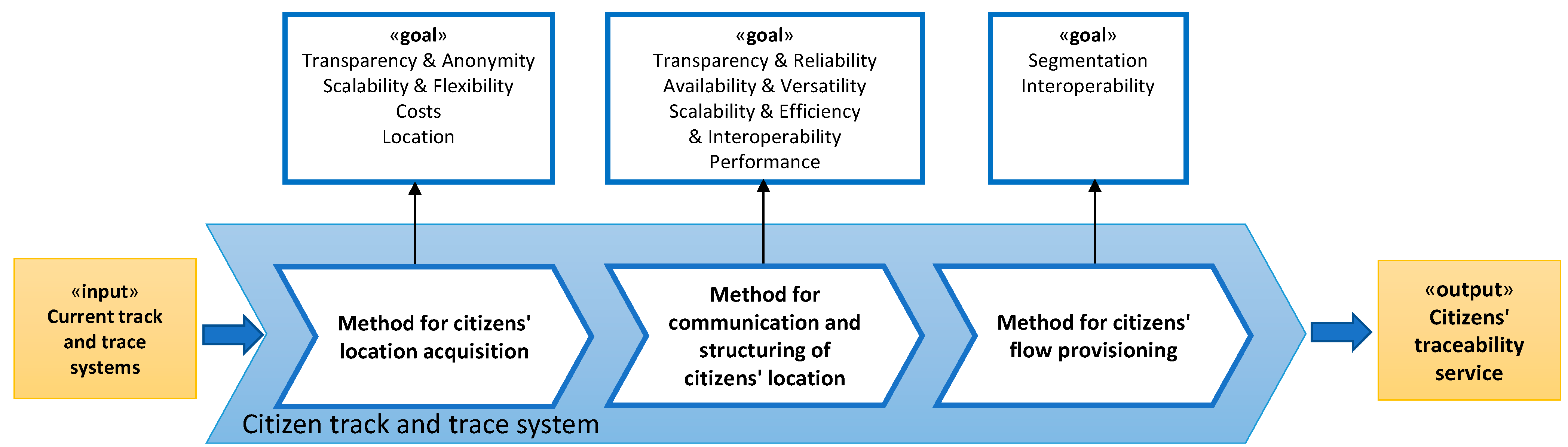
3.1. Method for Citizens’ Location Acquisition
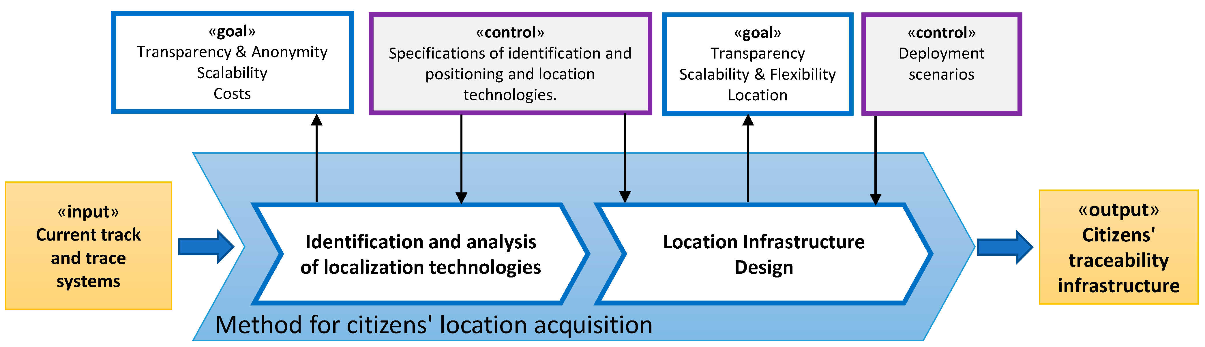
3.1.1. Identification and Analysis of Localization Technologies
| Technology | GPS | RFID/NFC | Wireless Networks |
|---|---|---|---|
| Main architecture | Triangulation positioning by satellite. | Set of antennas or readers and receivers. | Set of antennas or readers and receivers. |
| Communication | The user receiver obtains the signal from satellites and calculates the position. | Readers inspect receivers to determine whether they are present. | Receivers report that they are present. |
| Operating frequency | 1100 MHz to 1600 MHz | Active: 455 MHz, 2.45 GHz, 5.8 GHz; Passive: 128 KHz, 13.6 MHz, 915 MHz, 2.45 GHz | Wi-Fi: 2.4 GHz, 5 GHz; WiMax: 2.3 GHz, 3.5 GHz; Cellular mobile: 800 MHz, 1900 MHz, others. |
| Cover | Worldwide; Outdoor environment | Depending on antenna network deployed. Outdoor and indoor environments | Depending on antenna network deployed. Outdoor and indoor environments. |
| Range | Worldwide | Active: ~100 m; Passive: 0 to few meters | Wi-Fi: 30 to 100 m WiMax: ~50 km; Cellular mobile: ~35 km |
| Power consumption | Very high | Passive tags receiver: Very low. | Very high |
| Deployment Costs | Satellites: Already deployed and free to use; Present in mobile devices | Need to deploy readers network. Present in mobile devices and other everyday user accessories. | Need to deploy antenna network. Present in mobile devices and other user accessories. |
| Localization | Receiver position. | Antenna position. | Antenna position. |
| Transparency and Anonymity | Low | High | Low |
| Usual application | Navigation, topography, land levelling, etc. | Identification, access control, payment, etc. | Internet access and communication services. |
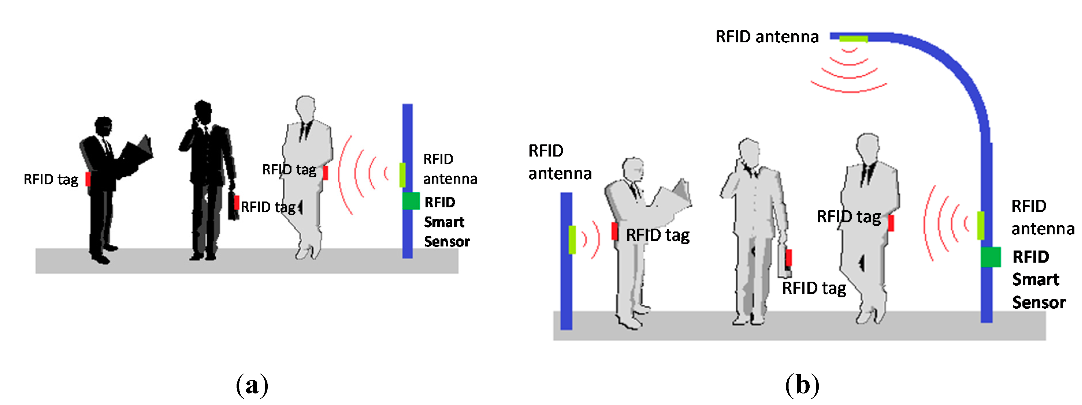
3.1.2. Location Infrastructure Design

3.2. Method for Communication and Structuring of Citizens’ Location
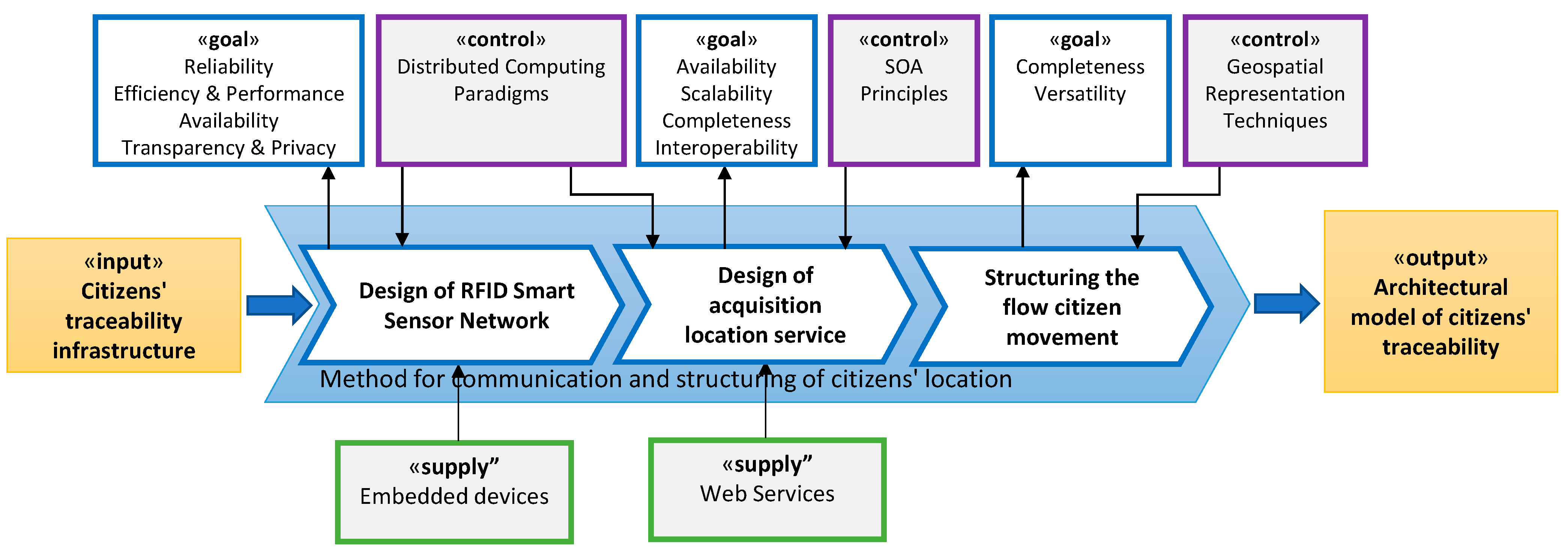
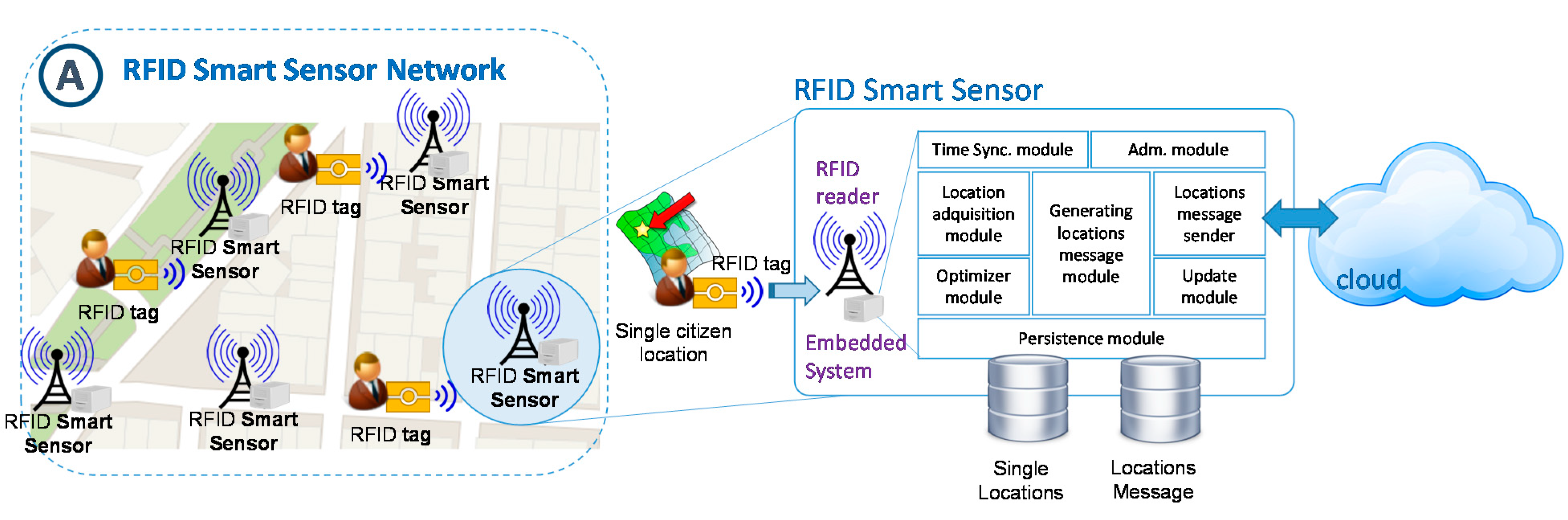
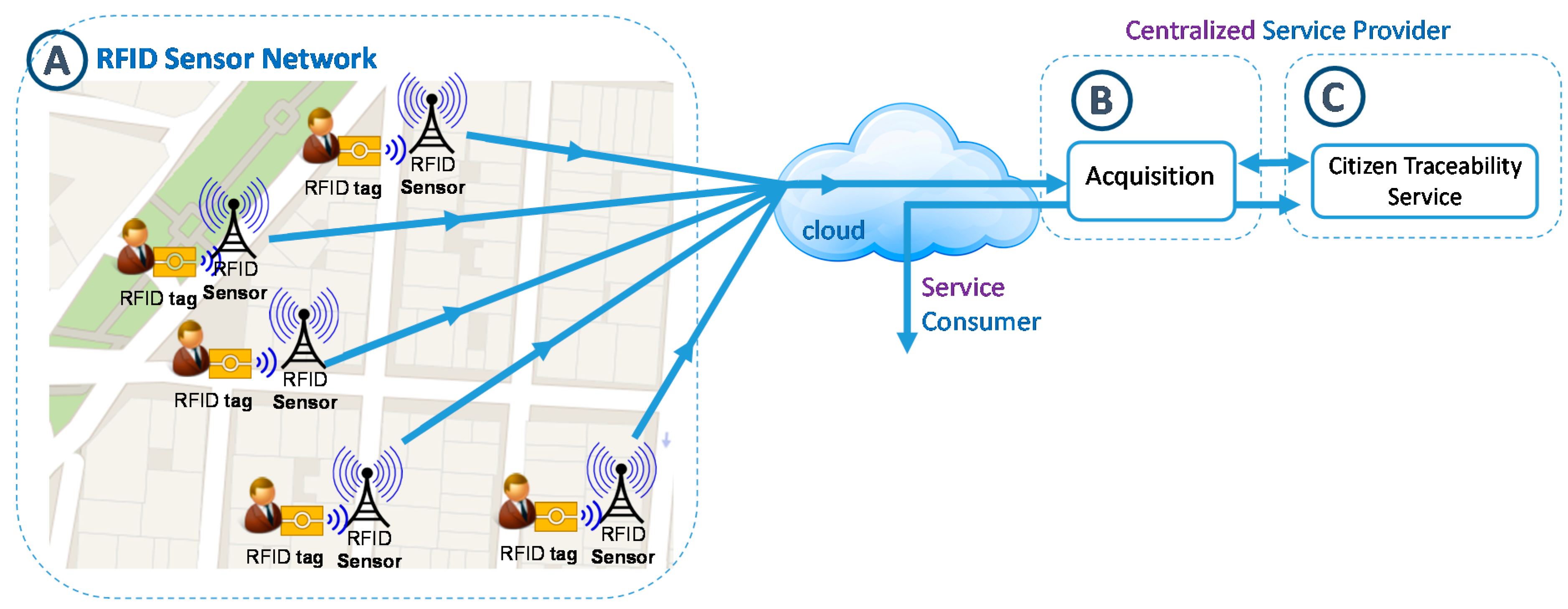
3.2.1. Design of RFID Smart Sensor Network

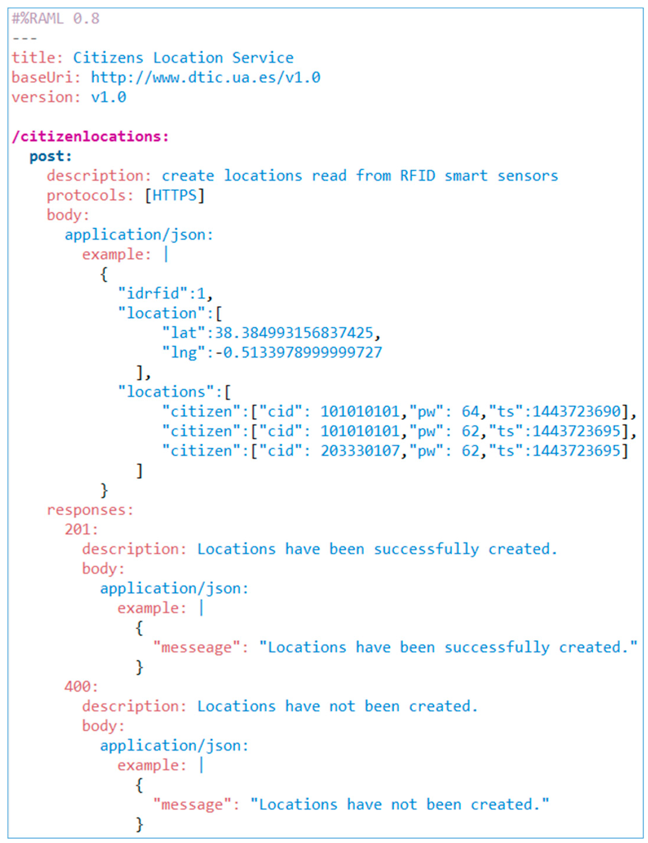
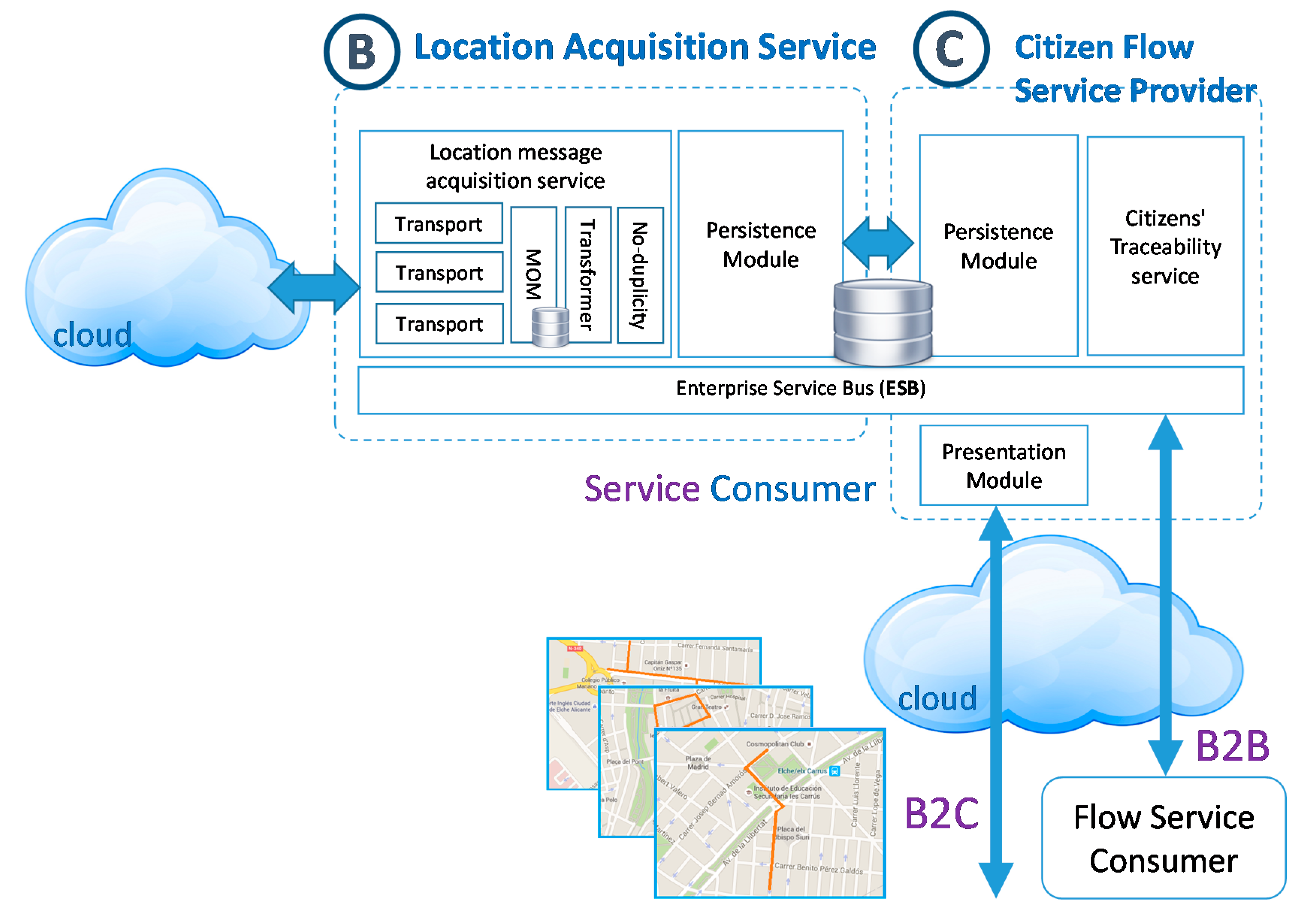
3.2.2. Design of Acquisition Location Service
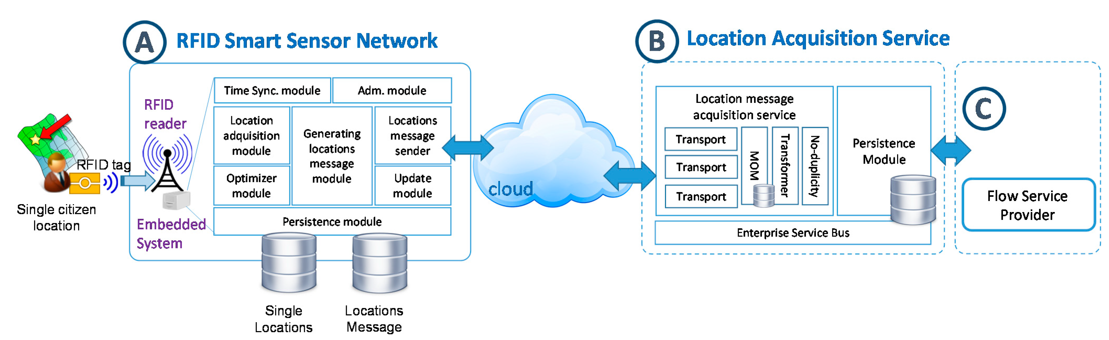
3.2.3. Structuring the Citizen Movement Flow
- •
- rfss (lo, la) represents the location of the RFID Smart Sensor determined by its longitude and latitude, which will allow us to know the position of the citizen on the map.
- •
- cid represents the radio-frequency identification which is carried by the citizens and which allows us to identify them in a unique and anonymous way.
- •
- pw it is the power of a certain card reading signal which will allow us to know the proximity to the RFID Smart Sensor antenna. Based on this, the information on the RFID Smart Sensor will be preprocessed in order to eliminate redundant locations with no added value which belong to the same user and will help determine possible directions of a citizen or trajectory changes with the data from other neighbouring RFID Smart sensor.
- •
- ts it is the moment in time in which the RFID tag reading took place.
- •
- RFSSN represents the set of RFID Smart Sensors that make up the sensor network.
- •
- RFSSk is a specific sensor defined by its unique identifier (idk), its position, determined by the longitude (lok) and latitude (lak), and the set of its neighbouring smart sensors (Nk), which in turn will be a subset of the network (note that the geographical-neighbours of a sensor could not match with its real neighbours due to insurmountable obstacles or habits of movement of citizens).
3.3. Method for Provisioning Citizen Flow

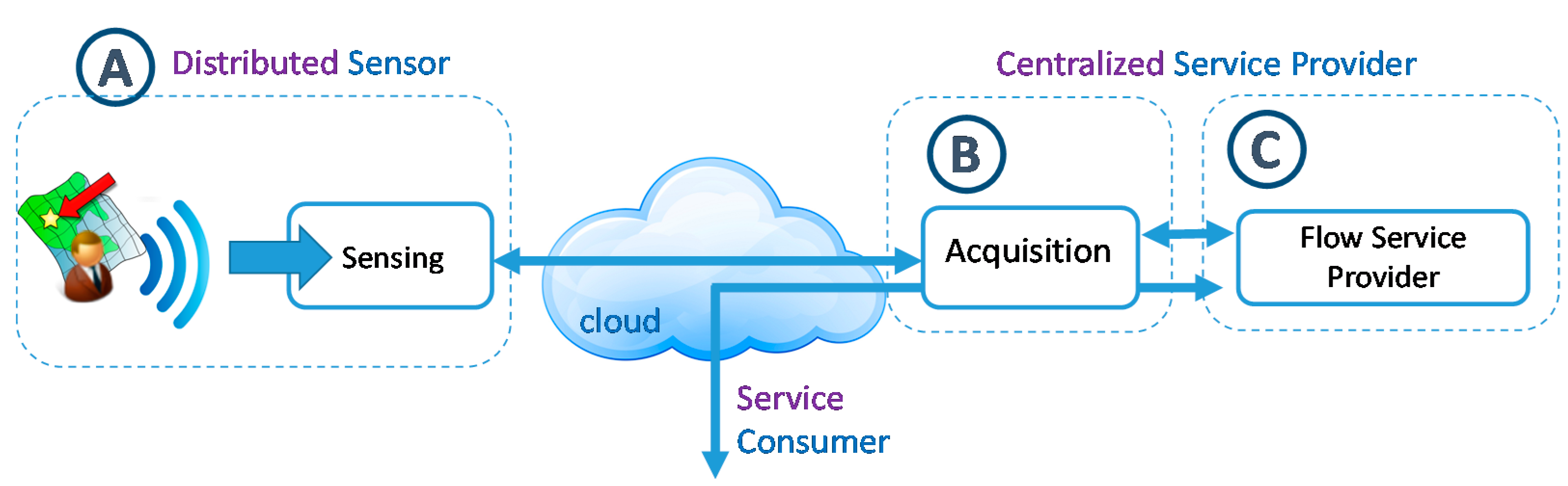
4. Implementation and Validation
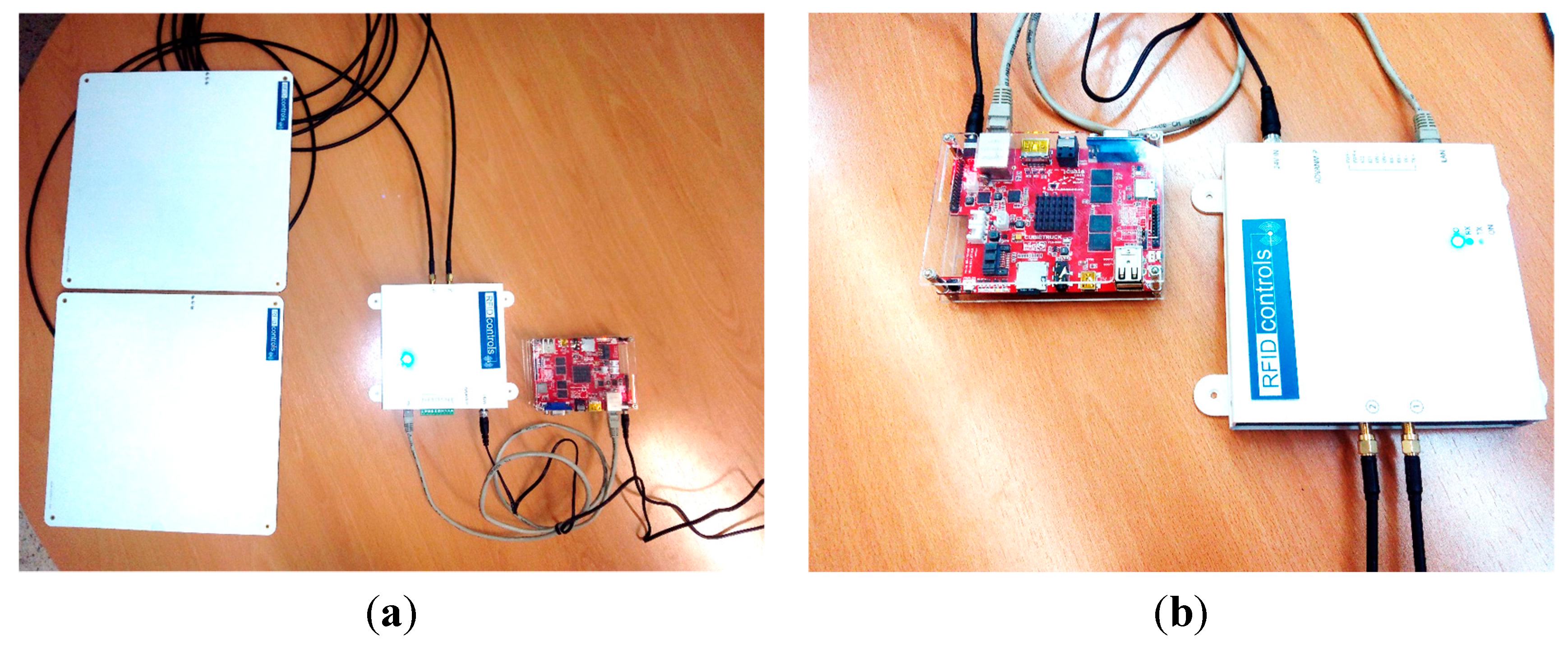
4.1. Implementation

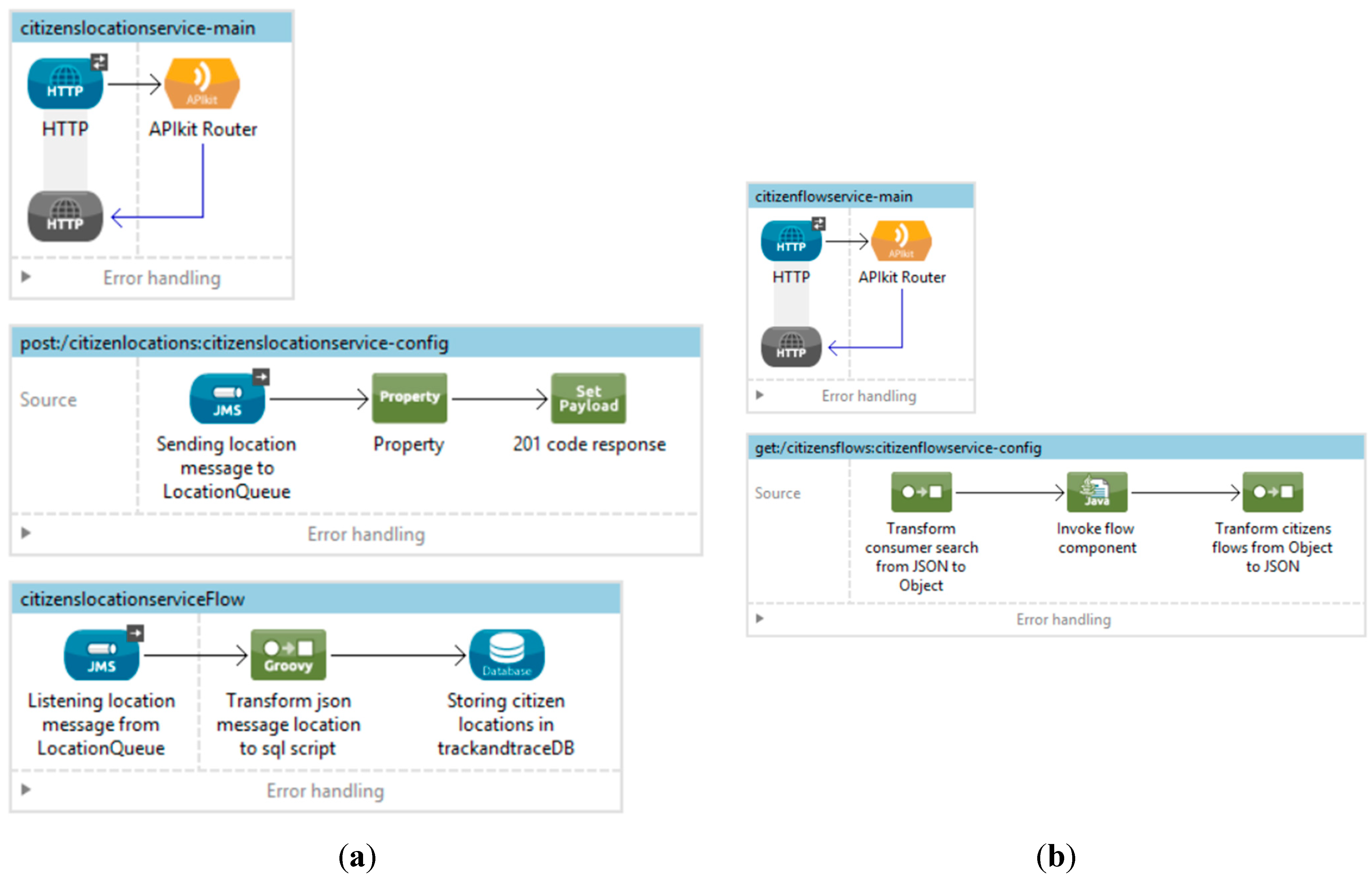

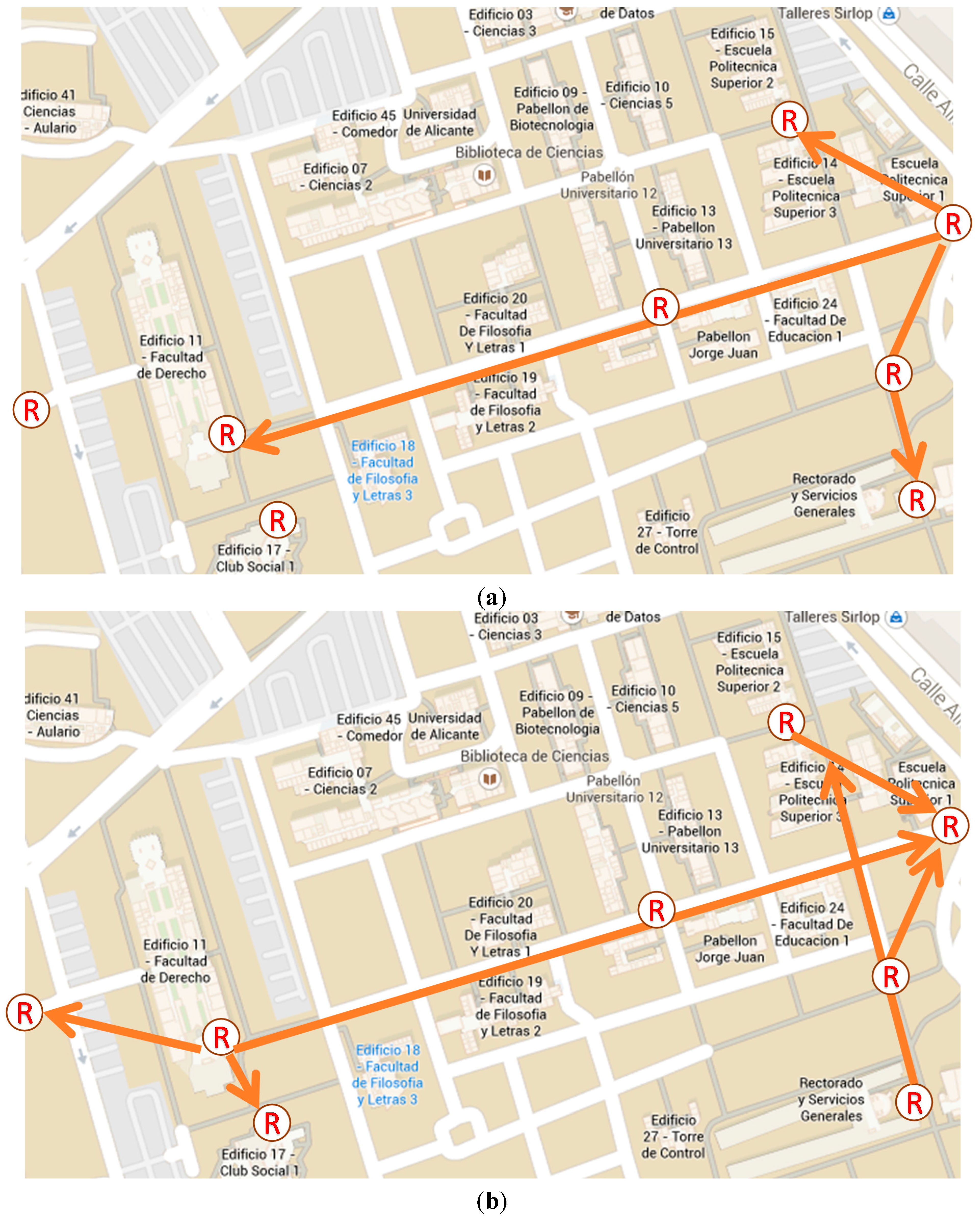
4.2. Case Study

| Research Work | Main Functionality | Transparency & Anonymity | Working Environments | Reliability | Energy Consumption | Scalability |
|---|---|---|---|---|---|---|
| Proposed architecture | Track & trace | Yes. No user interaction & Independency of RFID tags | Indoor & outdoor | Yes | No (passive tags) | Yes. (Distributed and decoupled approach) |
| GPS proposals [27,28,29,30] | Track & trace | No. User interaction | Outdoor | No | High | No |
| Wi-Fi proposals [16,34] | Track | No. User interaction | Indoor & outdoor | No | High | No |
| CCTV | Surveillance | No. Surveillance cameras | Indoor & outdoor | No | High | Yes |
| Science museum [42] | Track & trace | No. User/Object interaction & Dependency of own RFID tags | Indoor | No | No (passive tags) | No |
| Oyster Card [40] | Track & trace | No. Dependency of own RFID tags | Indoor & outdoor | No | No (passive tags) | No |
| Blind/inside RFID [47,53] | Track | No. User interaction & Dependency of own RFID tags | Indoor & outdoor | No | No (passive tags) | No |
| REACT [58] | Track | No. User/Object interaction & Dependency of own RFID tags | Outdoor | No | No (passive tags) | Yes |
| LANDMARC [41,46] | Track | No. User/Object interaction & Dependency of own RFID tags | Indoor | No | Yes (active tags) | No |
| Peer-to-Peer Networks [57] | Track | No. User/Object interaction & Dependency of own RFID tags | Indoor | No | Yes (active tags) | Yes |
| iWalker [44] | Track | No. User/Object interaction & Dependency of own RFID tags | Indoor | No | No (passive tags) | No |
| Other [45,48,50,51,52,54,55,56] | Track | No. User/Object interaction & Dependency of own RFID tags | Indoor | No | No (passive tags) | In controlled env. only [45,55] |
5. Conclusions
Acknowledgments
Author Contributions
Conflicts of Interest
References
- Neirotti, P.; de Marco, A.; Cagliano, A.C.; Mangano, G.; Scorrano, F. Current trends in Smart City initiatives: Some stylised facts. Cities 2014, 38, 25–36. [Google Scholar] [CrossRef]
- Smart Cities Council. Available online: http://smartcitiescouncil.com (accessed on 9 June 2015).
- OECD, Governing the City. Available online: http://dx.dir.org/10.1787/9889264226500-en (accessed on 9 June 2015).
- European Smart Cities. Available online: http://www.smart-cities.eu/ (accessed on 9 June 2015).
- Fietkiewicz, K.; Pyka, S. Development of informational cities in Japan: A regional comparison. Int. J. Knowl. Soc. Res. 2014, 5. [Google Scholar] [CrossRef]
- Fazio, M.; Puliafito, A.; Villari, M. IoT4S: A new architecture to exploit sensing capabilities in smart cities. Int. J. Web Grid Serv. 2014, 10, 114–138. [Google Scholar] [CrossRef]
- Atzoria, L.; Ierab, A.; Morabito, G. The Internet of things: A survey. Comput. Netw. 2010, 54, 2787–2805. [Google Scholar] [CrossRef]
- Mitton, N.; Papavassiliou, S.; Puliafito, A.; Trivedi, K.S. Combining Cloud and sensors in a smart city environment. EURASIP J. Wirel. Commun. Netw. 2012, 2012, 247. [Google Scholar] [CrossRef]
- Stankovic, J.A. Research directions for the internet of things. IEEE Internet Things J. 2014, 1, 3–9. [Google Scholar] [CrossRef]
- Gubbia, J.; Buyyab, R.; Marusica, S.; Palaniswamia, M. Internet of things (IoT): A vision, architectural elements, and future directions. Future Gener. Comput. Syst. 2013, 29, 1645–1660. [Google Scholar] [CrossRef]
- Choi, S.H.; Yang, B.; Cheung, H.H.; Yang, Y.X. RFID tag data processing in manufacturing for track-and-trace anti-counterfeiting. Comput. Ind. 2015, 68, 148–161. [Google Scholar] [CrossRef]
- Shia, J.; Lia, Y.; Heb, W.; Sima, D. SecTTS: A secure track & trace system for RFID-enabled supply chains. Comput. Ind. 2012, 63, 574–585. [Google Scholar]
- Kang, Y.S.; Lee, Y.H. Development of generic RFID traceability services. Comput. Ind. 2013, 64, 609–623. [Google Scholar] [CrossRef]
- Muñoz-Gea, J.P.; Malgosa-Sanahuja, J.; Manzanares-Lopez, P.; Sanchez-Aarnoutse, J.C. Implementation of traceability using a distributed RFID-based mechanism. Comput. Ind. 2010, 61, 480–496. [Google Scholar] [CrossRef]
- Todorovica, V.; Neagb, M.; Lazarevica, M. On the usage of RFID tags for tracking and monitoring of shipped perishable goods. Proced. Eng. 2014, 69, 1345–1349. [Google Scholar] [CrossRef]
- Isaak, J. Cell Phone WiFi Used to Track Your Location. Available online: http://ieeessit.org/2014/01/16/cell-phone-wifi-used-to-track-your-location-2/ (accessed on 9 June 2015).
- International Telecommunication Union. Aggregate Data 2006–2013 ICT Data for the World, by Geographic Regions and by Level of Development; ITU: Geneva, Switzerland, 2014. [Google Scholar]
- Kelly, J.; Jones, P.; Barta, F.; Hossinger, R.; Witte, A.; Wolf, A.C. Successful Transport Decision-Making: A Project Management and Stakeholder Engagement Handbook; European Commission: Brussels, Belgium, 2004. [Google Scholar]
- Allport, R.; Brown, R.; Glaister, S.; Travers, T. Success and Failure in Urban Transport Infrastructure Projects; KPMG Intternational: Amsterdam, The Netherlands, 2008. [Google Scholar]
- Bickerstaff, K.; Tolley, R.; Walker, G. Transport planning and participation: The rhetoric and realities of public involvement. J. Transp. Geogr. 2002, 10, 61–73. [Google Scholar] [CrossRef]
- Galland, S.; Lamotte, O.; Gaud, N. MetroB: Evaluation and simulation of public transport system. In Proceedings of the IET International Conference on Smart and Sustainable City, Shanghai, China, 6–8 July 2011.
- Giannotti, F.; Nanni, M.; Pedreschi, D.; Pinelli, F.; Renso, C.; Rinzivillo, S.; Trasarti, R. Mobility data mining: Discovering movement patterns from trajectory data. In Proceedings of the Second International Workshop on Computational Transportation Science, San Jose, CA, USA, 2 November 2010; pp. 7–10.
- Batty, M.; Axhausen, K.; Giannotti, F.; Pozdnoukhov, A.; Bazzani, A.; Wachowicz, M.; Ouzounis, G.; Portugali, Y. Smart cities of the future. Eur. Phys. J. Spec. Top. 2012, 214, 481–518. [Google Scholar] [CrossRef]
- Schmitt, G. A planning environment for the design of future cities. In Digital Urban Modelling and Simulation; Springer: Berlin, Germany, 2012; pp. 3–16. [Google Scholar]
- Bajaj, R.; Ranaweera, S.L.; Agrawal, D.P. GPS: Location-tracking technology. Computer 2002, 35, 92–94. [Google Scholar]
- Moloo, R.K.; Digumber, V.K. Low-cost mobile GPS tracking solution. In Proceedings of the 2011 International Conference on Business Computing and Global Informatization, Shanghai, China, 29–31 July 2011; pp. 516–519.
- Trasarti, R.; Rinzivillo, S.; Pinelli, F.; Nanni, M.; Monreale, A.; Renso, C.; Pedreschi, D.; Giannotti, F. Exploring Real Mobility Data with M-atlas. In Machine Learning and Knowledge Discovery in Databases; Springer: Berlin, Germany, 2010; pp. 624–627. [Google Scholar]
- Yuan, J.; Zheng, Y.; Zhang, C.; Xie, W.; Xie, X.; Sun, G.; Huang, Y. T-drive: Driving directions based on taxi trajectories. In Proceedings of the 18th ACM SIGSPATIAL International Conference on Advances in Geographic Information Systems, San Jose, CA, USA, 2–5 November 2010; pp. 99–108.
- Trasarti, R.; Nanni, M.; Giannotti, F.; Pedreschi, D.; Renso, C. A query language for mobility data mining. Int. J. Data Warehous. Min. 2011, 7, 24–45. [Google Scholar] [CrossRef]
- Iqbal, M.U.; Lim, S. Privacy implications of automated GPS tracking and profiling. IEEE Technol. Soc. Mag. 2010, 29, 39–46. [Google Scholar] [CrossRef]
- Michaela, K.; Clarke, R. Location and tracking of mobile devices: Überveillance stalks the streets. Comput. Law Secur. Rev. 2013, 29, 216–228. [Google Scholar] [CrossRef]
- Clarke, R.; Wigan, M.R. You are where you’ve been: The privacy implications of location and tracking technologies. J. Locat. Based Serv. 2011, 5, 138–155. [Google Scholar] [CrossRef]
- Dahunsi, F.; Dwolatzky, B. An empirical investigation of the accuracy of location-based services in South Africa. J. Locat. Based Serv. 2012, 6, 22–34. [Google Scholar] [CrossRef]
- Zhang, Y.; Li, L.; Zhang, Y. Research and design of location tracking system used in underground mine based on WiFi technology. In Proceedings of the International Forum on Computer Science-Technology and Applications, Chongqing, China, 25–27 December 2009.
- Chen, P.-C. A cellular based mobile location tracking system. In Proceedings of the IEEE 49th Vehicular Technology Conference, Houston, TX, USA, 16–20 May 1999.
- Mitra, S.; DasBit, S. On location tracking and load balancing in cellular mobile environment-a probabilistic approach. In Proceedings of the International Conference on Electrical and Computer Engineering, Dhaka, Bangladesh, 20–22 December 2008; pp. 121–126.
- Chawla, V.; Ha, D.S. An overview of passive RFID. IEEE Commun. Mag. 2007, 45, 11–17. [Google Scholar] [CrossRef]
- Weinstein, R. RFID: A technical overview and its application to the enterprise. IT Prof. 2005, 7, 27–33. [Google Scholar] [CrossRef]
- Ni, L.M.; Zhang, D.; Souryal, M.R. RFID-based localization and tracking technologies. IEEE Wirel. Commun. 2011, 18, 45–51. [Google Scholar] [CrossRef]
- Bagchi, M.; White, P.R. The potential of public transport smart card data. Transp. Policy 2005, 12, 464–474. [Google Scholar] [CrossRef]
- Ni, L.M.; Liu, Y.; Lau, Y.C.; Patil, A.P. LANDMARC: Indoor location sensing using active RFID. Wirel. Netw. 2004, 10, 701–710. [Google Scholar] [CrossRef]
- Kanda, T.; Shiomi, M.; Perrin, L.; Nomura, T.; Ishiguro, H.; Hagita, N. Analysis of people trajectories with ubiquitous sensors in a science museum. In Proceedings of the IEEE International Conference on Robotics and Automation, Roma, Italy, 10–14 April 2007; pp. 4846–4853.
- Pandit, A.A.; Talreja, J.; Mundra, A.K. RFID tracking system for vehicles (RTSV). In Proceedings of the First International Conference on Computational Intelligence, Communication Systems and Networks, Indore, India, 23–25 July 2009.
- Kulyukin, V.; Kutiyanawala, A.; LoPresti, E.; Matthews, J.; Simpson, R. iWalker: Toward a rollator-mounted wayfinding system for the elderly. In Proceedings of the IEEE International Conference on RFID, Las Vegas, NV, USA, 16–17 April 2008.
- Li, Z.; Chu, C.-H.; Yao, W. SIP-RLTS: An RFID location tracking system based on SIP. In Proceedings of the IEEE International Conference on RFID, Las Vegas, NV, USA, 16–17 April 2008.
- Han, K.; Cho, S.-H. Advanced LANDMARC with adaptive knearest algorithm for RFID location system. In Proceedings of the International Conference on Network Infrastructure and Digital Content, Beijing, China, 24–26 September 2010; pp. 595–598.
- Willis, S.; Helal, S. A Passive RFID Information Grid for Location and Proximity Sensing for the Blind User; Technical Report Number TR04-009; University of Florida: Gainesville, FL, USA, 2004. [Google Scholar]
- Iturralde, D. A new system based on web services and RFID for tracking people in a pervasive mining environment. In Proceedings of the Latin-America Conference on Communications (LATINCOM), Santiago, Chile, 24–26 November 2013.
- Buccafurri, F.; Lax, G.; Nicolazzo, S.; Nocera, A. A privacy-preserving solution for tracking people in critical environments. In Proceedings of the 38th International Computer Software and Applications Conference Workshops (COMPSACW), Vasteras, Sweden, 21–25 July 2014; pp. 146–151.
- Nohara, K.; Tajika, T.; Shiomi, M.; Kanda, T.; Ishiguro, H.; Hagita, N. Integrating passive RFID tag and person tracking for social interaction in daily life. In Proceedings of the IEEE 17th International Symposium on Robot and Human Interactive Communication, Munich, Geramny, 1–3 August 2008; pp. 545–552.
- Germa, T.; Tajika, T.; Shiomi, M.; Kanda, T.; Ishiguro, H.; Hagita, N. Vision and RFID data fusion for tracking people in crowds by a mobile robot. Comput. Vis. Image Underst. 2010, 114, 641–651. [Google Scholar] [CrossRef]
- Cucchiara, R.; Fornaciari, M.; Haider, R.; Mandreoli, F.; Prati, A. Identification of intruders in groups of people using cameras and RFIDs. In Proceedings of the ACM/IEEE International Conference on Distributed Smart Cameras (ICDSC), Ghent, Belgium, 22–25 August 2011.
- Foster, K.R.; Jaeger, J. RFID inside. IEEE Spectrum. 1 March 2007. Available online: http://spectrum.ieee.org/computing/hardware/rfid-inside (accessed on 10 June 2015).
- Matic, A.; Osmani, V.; Mayora, O. RFID-based system for tracking people: Approaches to tagging demented patients. Lect. Notes Inst. Comput. Sci. Soc. Inform. Telecommun. Eng. 2011, 70, 60–65. [Google Scholar]
- Xiong, Z. Hybrid WSN and RFID indoor positioning and tracking system. EURASIP J. Embed. Syst. 2013, 2013, 6. [Google Scholar] [CrossRef]
- Hsu, C.-C.; Chen, J.-H. A novel sensor-assisted RFID-based indoor tracking system for the elderly living alone. Sensors 2011, 11, 10094–10113. [Google Scholar] [CrossRef] [PubMed]
- Hui, F.C.P.; Chan, H.C.B.; Fung, S.H. RFID-based location tracking system using a peer-to-peer network architecture. In Proceedings of the International MultiConference of Engineers and Computer Scientists, Hong Kong, China, 12–14 March 2014.
- Lin, X.; Lu, R.; Kwan, D.; Shen, X. REACT: An RFID-based privacy-preserving children tracking scheme for large amusement parks. Comput. Netw. 2010, 54, 2744–2755. [Google Scholar] [CrossRef]
- Steffen, R.; Preißinger, J.; Schöllermann, T.; Müller, A.; Schnabel, I. Near field communication (NFC) in an automotive environment. In Proceedings of the 2nd International Workshop on Near Field Communication, Monaco, 20 April 2010; pp. 15–20.
- Firence Card. Available online: http://www.firenzecard.it/?lang=en (accessed on 9 June 2015).
- ExxonMobil’s Speed-Pass. Available online: http://www.speedpass.com (accessed on 9 June 2015).
- Washington Metropolitan Area Transit Authority. Shuttle Services at Metro Facilities Report; WMATA: Washington, DC, USA, 2011. [Google Scholar]
- Collins, J. Gift Cards Go Contactless. Available online: http://www.rfidjournal.com/articles/view?762 (accessed on 9 June 2015).
- Charette, R. Wal-mart to track clothing with RFID Tags. IEEE Spectrum. 27 July 2010. Available online: http://spectrum.ieee.org/riskfactor/computing/it/walmart-to-track-clothing-with-rfid-tags (accessed on 9 June 2015).
- Marks & Spencer Embraces Change. RFID J. 2014. Available online: https://www.rfidjournal.com/purchase-access?type=Article&id=11952&r=%2Farticles%2Fview%3F11952 (accessed on 9 June 2015).
- Zara Builds Its Business around RFID. The Wall Street Journal. 16 September 2014. Available online: http://www.wsj.com/articles/at-zara-fast-fashion-meets-smarter-inventory-1410884519 (accessed on 9 June 2015).
- Special NRF Report: Decathlon Develops RFID to Revolutionise Stores and Back of House. The Retail Bulletin. 17 January 2014. Available online: http://www.theretailbulletin.com/news/special_nrf_reportdecathlon_develops_rfid_to_revolutionise_stores_and_back_of_house_17-01-14/ (accessed on 9 June 2015).
- Gilart-Iglesias, V.; Maciá-Pérez, F.; Marcos-Jorquera, D.; Mora-Gimeno, F.J. Industrial machines as a service: Modelling industrial machinery processes. In Proceedings of the 5th IEEE International Conference on Industrial Informatics, Vienna, Austria, 23–27 June 2007; pp. 23–27.
- Andújar-Montoya, M.D.; Gilart-Iglesias, V.; Montoyo, A.; Marcos-Jorquera, D. A construction management framework for mass customisation in traditional construction. Sustainability 2015, 7, 5182–5210. [Google Scholar] [CrossRef]
- Eriksson, H.E.; Penker, M. Business Modelling with UML; John Wiley & Sons: Hoboken, NJ, USA, 2001. [Google Scholar]
- García-Chamizo, J.M.; Mora-Pascual, J.; Mora-Mora, H.; Signes-Pont, M.T. Calculation methodology for flexible arithmetic processing. In Proceedings of the IFIP International Conference on Very Large Scale Integration (VLSI-SOC), Darmstadt, Germany, 1–3 December 2003; pp. 350–355.
- Mora-Mora, H.; Mora-Pascual, J.; García-Chamizo, J.M.; Jimeno-Morenilla, A. Real-time arithmetic unit. Real Time Syst. 2006, 34, 53–79. [Google Scholar] [CrossRef]
- Mora-Mora, H.; Mora-Pascual, J.; Signes-Pont, M.T.; Romero, J.L.S. Mathematical model of stored logic based computation. Math. Comput. Model. 2010, 52, 1243–1250. [Google Scholar] [CrossRef]
- Paul, A.S.; Wan, E.A. Wi-Fi based indoor localization and tracking using sigma-point Kalman filtering methods. In Proceedings of the IEEE/ION Position, Location and Navigation Symposium, Monterey, CA, USA, 5–8 May 2008; pp. 646–659.
- Dwoskin, E. What secrets your phone is sharing about you businesses use sensors to track customers, build shopper profiles. The Wall Street Journal. 13 January 2014. Available online: http://www.wsj.com/articles/SB10001424052702303453004579290632128929194 (accessed on 9 June 2015).
- Nikitin, P.V.; Rao, K.V.S. Performance limitations of passive UHF RFID systems. In Proceedings of the IEEE Antennas and Propagation Society International Symposium, Albuquerque, NM, USA, 9–14 July 2006; pp. 1011–1014.
- Li, N.; Becerik-Gerber, B. Performance-based evaluation of RFID-based indoor location sensing solutions for the built environment. Adv. Eng. Inform. 2011, 25, 535–546. [Google Scholar] [CrossRef]
- Das, R.; Harrop, P. RFID Forecasts, Players and Opportunities 2014–2024; IDTechEx: Cambridge, MA, USA, July 2014. Available online: http://www.centrenational-rfid.com/docs/users/file/RFID_Forecasts_2014_2024.pdf (accessed on 9 June 2015).
- Juels, A. RFID security and privacy: A research survey. IEEE J. Sel. Areas Commun. 2006, 24, 381–394. [Google Scholar] [CrossRef]
- Juels, A.; Rivest, R.L.; Szydlo, M. The blocker tag: Selective blocking of RFID tags for consumer privacy. In Proceedings of the ACM Conference on Computer and Communications Security, Washington, DC, USA, 27–30 October 2003; pp. 103–111.
- RFIDControls. Available online: http://www.rfidcontrols.com/ (accessed on 9 June 2015).
- Hohpe, G.; Woolf, B. Enterprise Integration Patterns, 1st ed.; Addison-Wesley: Boston, MA, USA, 2003. [Google Scholar]
- Sivrikaya, F.; Yener, B. Time synchronization in sensor networks: A survey. IEEE Netw. 2004, 18, 45–50. [Google Scholar] [CrossRef]
- Zhang, F.; Deng, G.Y. Probabilistic time synchronization in wireless sensor networks. Int. Conf. Wirel. Commun. Netw. Mob. Comput. 2005, 2, 980–984. [Google Scholar]
- Erl, T. SOA Design Patterns, 1st ed.; Prentice Hall: Upper Saddle River, NJ, USA, 2009. [Google Scholar]
- Cubietruck. Available online: http://www.cubietruck.com/ (accessed on 9 June 2015).
- Nikitin, P.V.; Rao, K.V.S. Antennas and propagation in UHF RFID systems. In Proceedings of the IEEE International Conference on RFID, Las Vegas, NV, USA, 16–17 April 2008; pp. 277–288.
- Chen, Z.N.; Qing, X.; Chung, H.L. A universal UHF RFID reader antenna. IEEE Trans. Microw. Theory Tech. 2009, 57, 1275–1282. [Google Scholar] [CrossRef]
© 2015 by the authors; licensee MDPI, Basel, Switzerland. This article is an open access article distributed under the terms and conditions of the Creative Commons Attribution license (http://creativecommons.org/licenses/by/4.0/).
Share and Cite
Mora-Mora, H.; Gilart-Iglesias, V.; Gil, D.; Sirvent-Llamas, A. A Computational Architecture Based on RFID Sensors for Traceability in Smart Cities. Sensors 2015, 15, 13591-13626. https://doi.org/10.3390/s150613591
Mora-Mora H, Gilart-Iglesias V, Gil D, Sirvent-Llamas A. A Computational Architecture Based on RFID Sensors for Traceability in Smart Cities. Sensors. 2015; 15(6):13591-13626. https://doi.org/10.3390/s150613591
Chicago/Turabian StyleMora-Mora, Higinio, Virgilio Gilart-Iglesias, David Gil, and Alejandro Sirvent-Llamas. 2015. "A Computational Architecture Based on RFID Sensors for Traceability in Smart Cities" Sensors 15, no. 6: 13591-13626. https://doi.org/10.3390/s150613591