
TF4SM: A Framework for Developing Traceability Solutions in Small Manufacturing Companies


Abstract
:1. Introduction
- Would the time response to inefficiencies improve by deploying a system based on our TF4SM in companies?
- Is it possible to reduce the number of inefficiencies in productive processes using a TF4SM-based system?
2. State of the Art in Traceability Systems, Different Theories of Networked Embedded Systems, and RFID-Based Products
2.1. Automated Industrial Processes and Traceability Systems: State of the Art
- There are some manufacturers that do not apply any traceability system, such as small handicraft companies where production processes do not generate intermediate products [33].
- Some companies implement systems based on invoices and control record sheets (commonly known as “system based on pen and paper” [34]). In these systems, each product carries a label with a serial number and a description. An operator is responsible for, at each stage of the production process, writing both data items in the appropriate form. Although these systems work fine, the use of IT enables a larger amount of data to be handled, and thereby it becomes realistic to develop traceability systems with very detailed information about both the product and its processing history [35,36].
- We find companies which implement systems based on Personal Digital Assistants (PDAs) [37]. In these systems, each product still carries a label with a serial number and a description; however, in this case the responsible operator, instead of using control record sheets, uses a PDA to transmit data in real-time. Although these systems reduce the time requirements related to traceability processes, they still are extremely sensitive to human errors.
- Around ten years ago, in order to reduce human errors in traceability systems, labels with the serial number and the description of each product were replaced by codes (e.g., QR or barcodes) storing both data [38]. Then, equipping PDAs with the appropriate reader is enough to avoid operators having to manually input any data.
- More recently, the old stickers with printed codes have been replaced by RFID labels [39]. This is basically due to two factors [40]: RFID tags can store kilobytes of information, and they also can include security and privacy policies (what it is especially important in confidential products). These systems have been widely applied in the manufacturing sector.
2.2. Networked Embedded Systems and Traceability Systems

| Feature and Requirements | Smart Space Along [7] | Smart Environments Along [1] | Smart Environments Along [5] | CPS From [15] | CPS From NIST |
|---|---|---|---|---|---|
| Object identification capability | ✓/✗ | ✗ | ✗ | ✓ | ✓/✗ |
| Real-time data capture | ✓ | ✓ | ✓ | ✓ | ✓ |
| Execution engine | ✗ | ✗ | ✗ | ✗ | ✓/✗ |
| Decision capability | ✗ | ✗ | ✗ | ✓/✗ | ✓ |
| Learning capability | ✗ | ✓ | ✗ | ✓/✗ | ✓ |
| Prosumer focused | ✗ | ✗ | ✗ | ✗ | ✓/✗ |
| Dynamical adaptation | ✓/✗ | ✓/✗ | ✓/✗ | ✓/✗ | ✓ |
| Vertical approach | ✗ | ✓ | ✗ | ✗ | ✓ |
| Can offer meaningful human-understandable information | ✗ | ✓ | ✓/✗ | ✓/✗ | ✓ |
2.3. RFID-Based Products
3. Analysis of Manufacturing Scenarios. TF4SM: First Prototype Design
3.1. Analysis of Manufacturing Scenarios: Motivation Scenario
- REQ#1: the event monitoring function and production task traceability must be independent of the location of the information source and the hardware used. Traditional control systems were limited to the capability of the controller residing inside.
- REQ#2: it should define a flexible and extensible architecture for the integration of various systems, wireless sensor networks (WSN), actuators, execution engines, among other things.
- REQ#3: it should be capable of suspending current operations when the data obtained is corrupt, the task performed does not correspond to the expected one and/or some defined rules for the tasks are not satisfied.
- REQ#4: the system must be easily configurable to allow communication with new elements and seamless interchange of new events. Traditional tag-based systems required early binding, that is, a configuration stage to link data sources and consumers of data.
- REQ#5: the infrastructure must be capable of identifying each user or user role to determine the task to be performed. User roles are also considered for the cases when regulation does not allow identification of employees.
- REQ#6: the system must assign tasks to different users who collaborate to complete the process.
- REQ#7: ability to reconstruct every production step. This is required both for regulatory compliance and as an important basis for production environments.
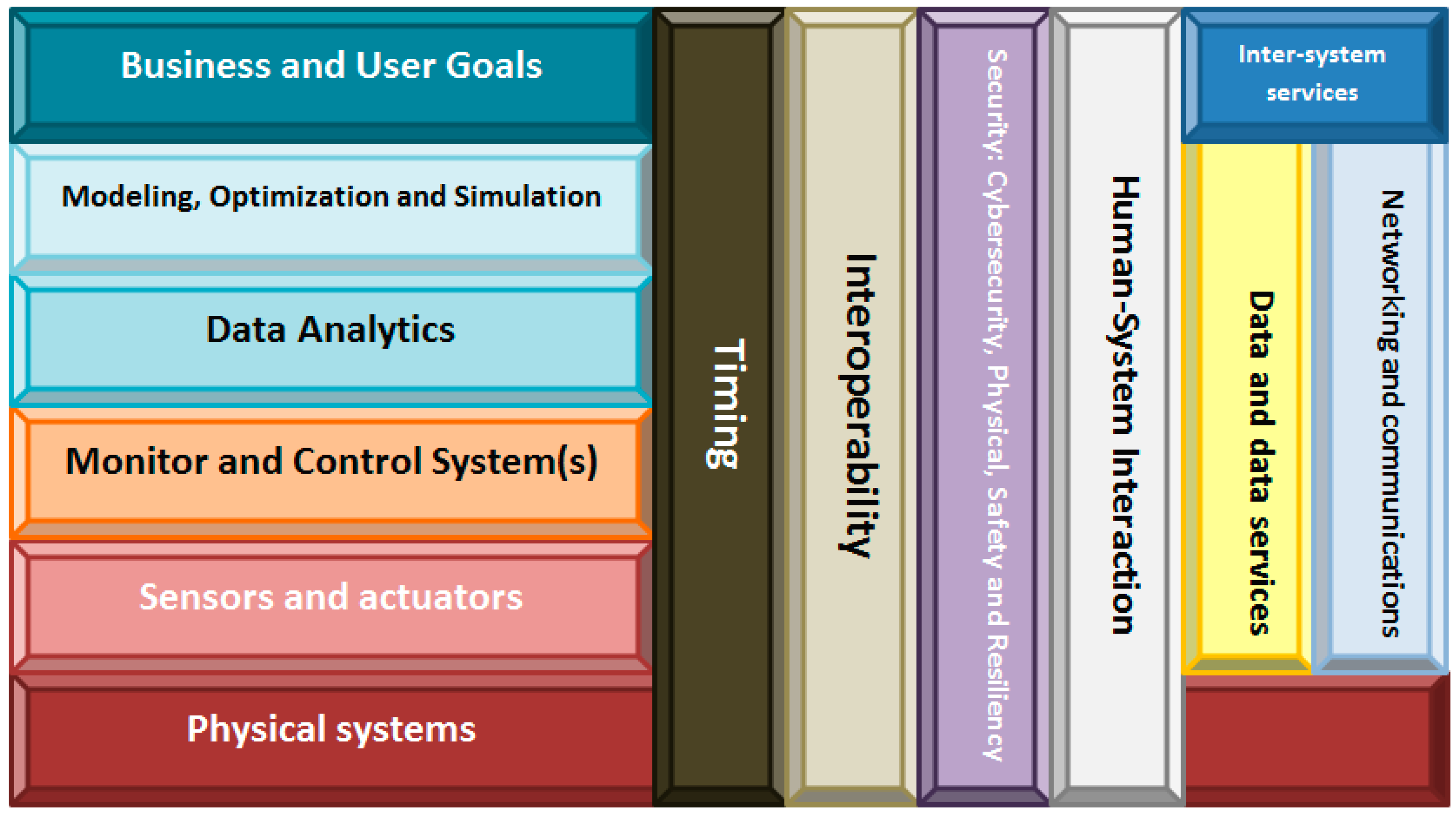
3.2. TF4SM: A New Traceability Framework for Small Manufacturing Companies

- The physical systems include all instruments, industrial systems and manufacturing elements and products present in the company’s facilities.
- Cybernetic devices layer refers to the embedded devices which contains RFID readers and/or RFID tags, as well as to all elements which make up the subjacent pervasive computing system [70]. The inclusion of mobile computing in the framework (we describe the communications plane later) partially covers REQ#1 (the system must show correct performance, independently of the information source’s location). In addition, working with embedded devices allows us to answer the third basic question about traceability systems: how to integrate RFID system into the company’s production processes. Although this paper refers to cybernetic devices, this kind of technologies has been commonly studied as “smart objects”. For example, in [71] the relevance of smart objects is highlighted in several application scenarios.
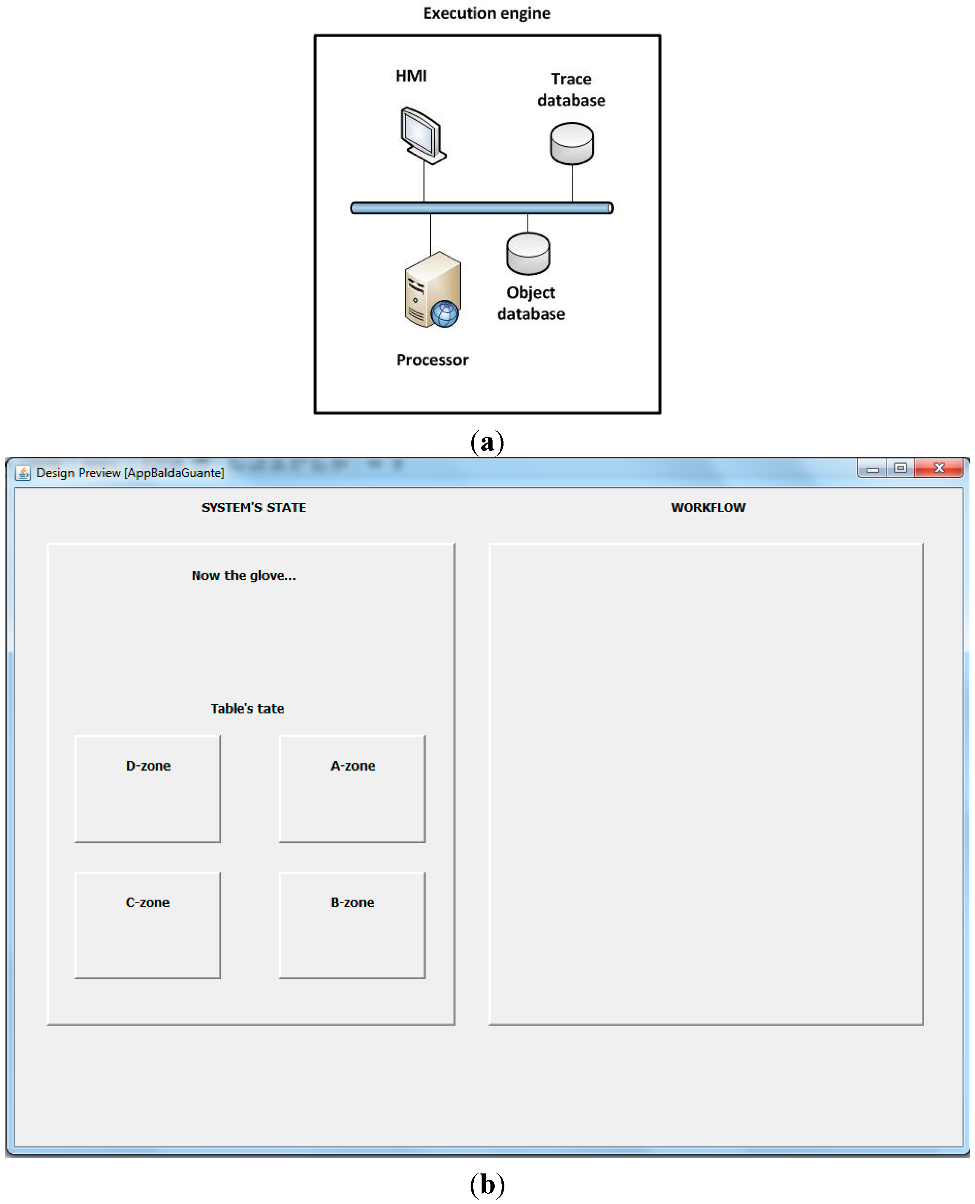
- The Monitor and Control System refer to the interlayer which adapts cybernetic devices to high level computing schemes. It contains, mainly, data acquisition from RFID readers and data pre-processing. The inclusion of this layer allows creating hardware independent traceability systems. Embedded devices are placed below this layer and knowledge feedback loops are defined on top. This breakdown between knowledge management processes and the hardware which supports the system agree fully with the second part of REQ#1.
- The Data Analytics layer, as in NIST reference architecture, processes data from different devices for pattern recognition and extracts data using machine learning and data mining. It also includes visual analytics oriented to the operator. Moreover, pattern recognition capability fulfills REQ#7 (which describes the ability to reconstruct every production step), as it allows inferring workers’ activities from data collected by RFID readers. The algorithms included in this layer also answer the last basic question which remains unresolved (how to translate the real-time data into meaningful information for the field operator?). Decision making uses results from Data Analytics as input for determining the next action which must be executed (issue an alert, suspend an operation, etc.). Thanks to the support of Data Analytics layer corrupt data can be detected, and this layer can order an operation to be suspended. In that way, REQ#3 is covered, and some desirable features are included.
- Finally, in the Business Goals layer, rules about alerts, user’s roles, minimum stock, automatic orders or emergency situations can be defined. The interface offered by the system at this level will be specific of the application domain (depend on the product manufactured in the company), so any technological expert must control the traceability system (what was desirable). As this layer is placed at human abstraction level, identities, workflows, tasks or collaborative work can be defined. Thus, REQ#5 and REQ#6 get fulfilled.
- Apart the previously described layers, the framework architecture includes six planes which cross vertically all the layers:
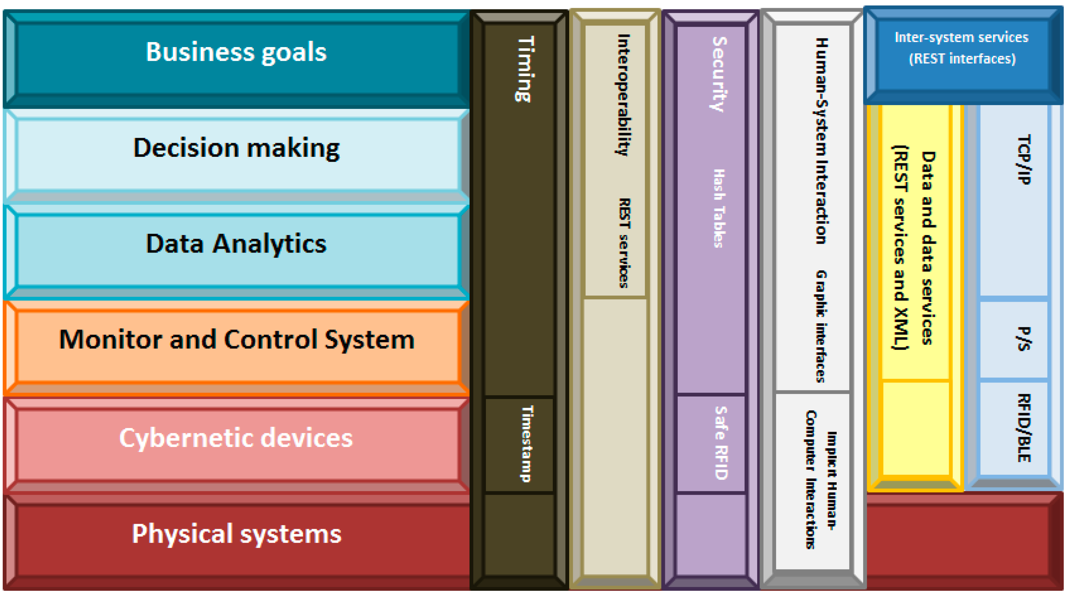
- Timing: In traceability systems, time issues are not critical. Therefore, in our framework timing has been resolved including a timestamp in each data produced by the cybernetic devices. Any other solution is considered as this datum is enough for tracing the products’ life;
- Interoperability: Traceability systems are conceived as corporative infrastructure, so typically any external access will be admitted. In the case of joining various systems, communication will be performed at high level through Representational State Transfer (REST) interfaces, much more flexible than other technologies;
- Security: Security systems native from RFID-based traceability systems (based on safe RFID tags [72] and hash tables) have been widely proved as enough safe, so we maintain the same technologies in our framework;
- Human-System interaction: Two different levels are distinguished. At cybernetic devices layer, any direct interface toward the physical world is described, so the communication will be based on Implicit Human-Computer Interaction (IHCI) [73]. In higher layers, specific graphical interfaces will be defined to communicate operators with the system;
- Data and data services: The same philosophy applied in the case of “Interoperability” is valid here;
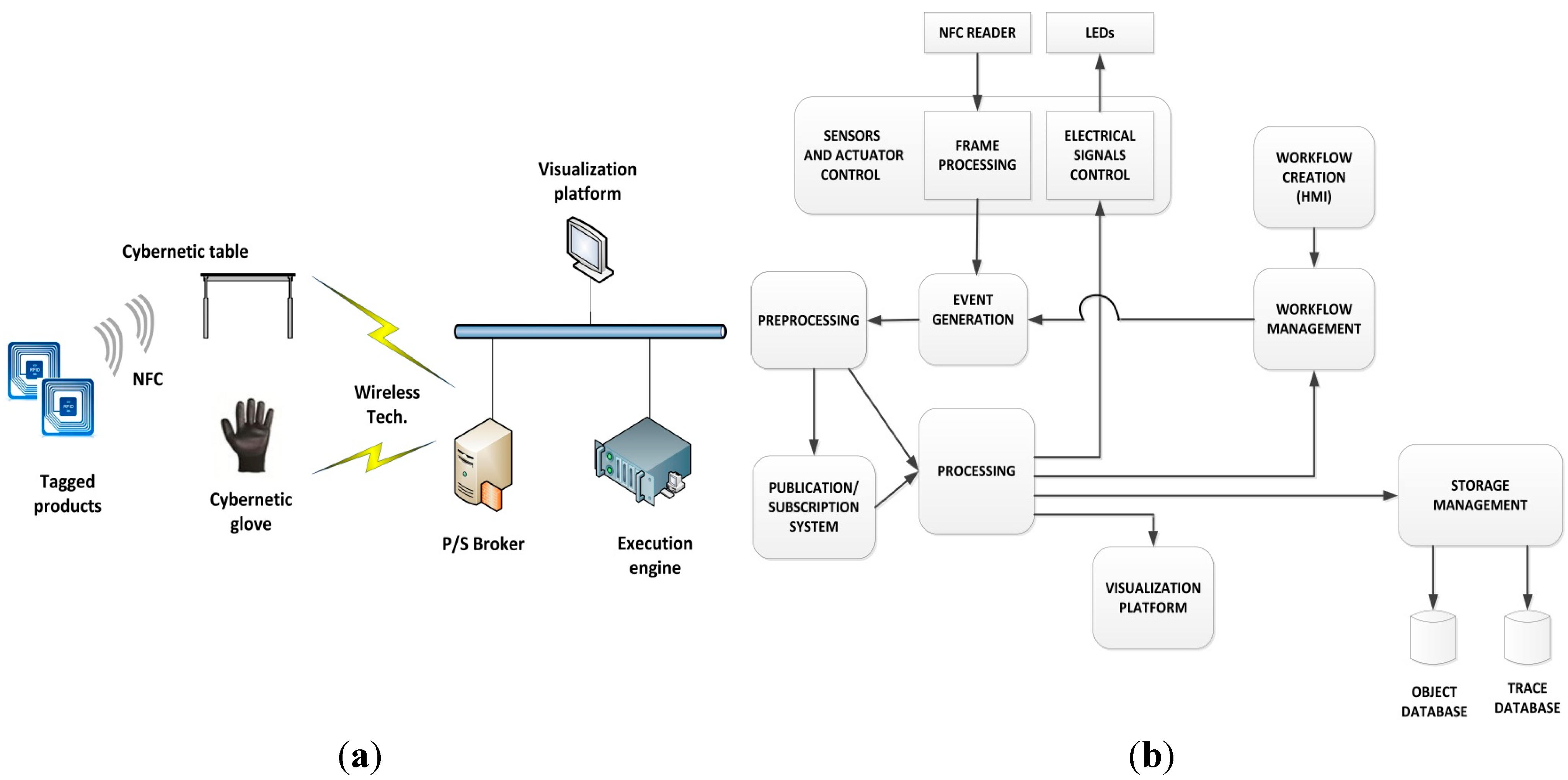
- Networking and communications: Communications must support a flexible architecture [74,75]. In order to achieve this objective four technologies coexist in our proposed framework. First, cybernetic devices must implement RFID technology (to trace products’ life) and Bluetooth Low-Energy (BLE) standard (to transmit the readings toward the monitor and control system). The use of wireless technologies, in addition, supports the creation of a mobile computing scheme. Second, over BLE, a Publish/Subscribe protocol will be deployed. Actually, the use of the Publish/Subscribe communication paradigm facilitates binding between data sources and consumers of data [76], as the intermediate entity called “broker” manages registration and decouples entities in time and space. This improves system architecture flexibility (which deals with REQ#4 and REQ#2), as data sources do not have to be aware of the existence or number of data consumers and vice versa. Furthermore, some Publish/Subscribe communication protocols, such as the Message Queuing Telemetry Transport (MQTT), support reliable communication that includes retransmission of lost frames and acknowledge events (which guaranteed the delivery of information). Finally, the communication among the monitor and control system and the higher abstraction layers will be performed over standard network technologies such as TCP/IP (which allows using the existent communications infrastructure in the company).
- Inter-systems services: One more time, the same philosophy applied in the case of “Interoperability” is valid here.
3.3. First Prototype Design

4. System Construction
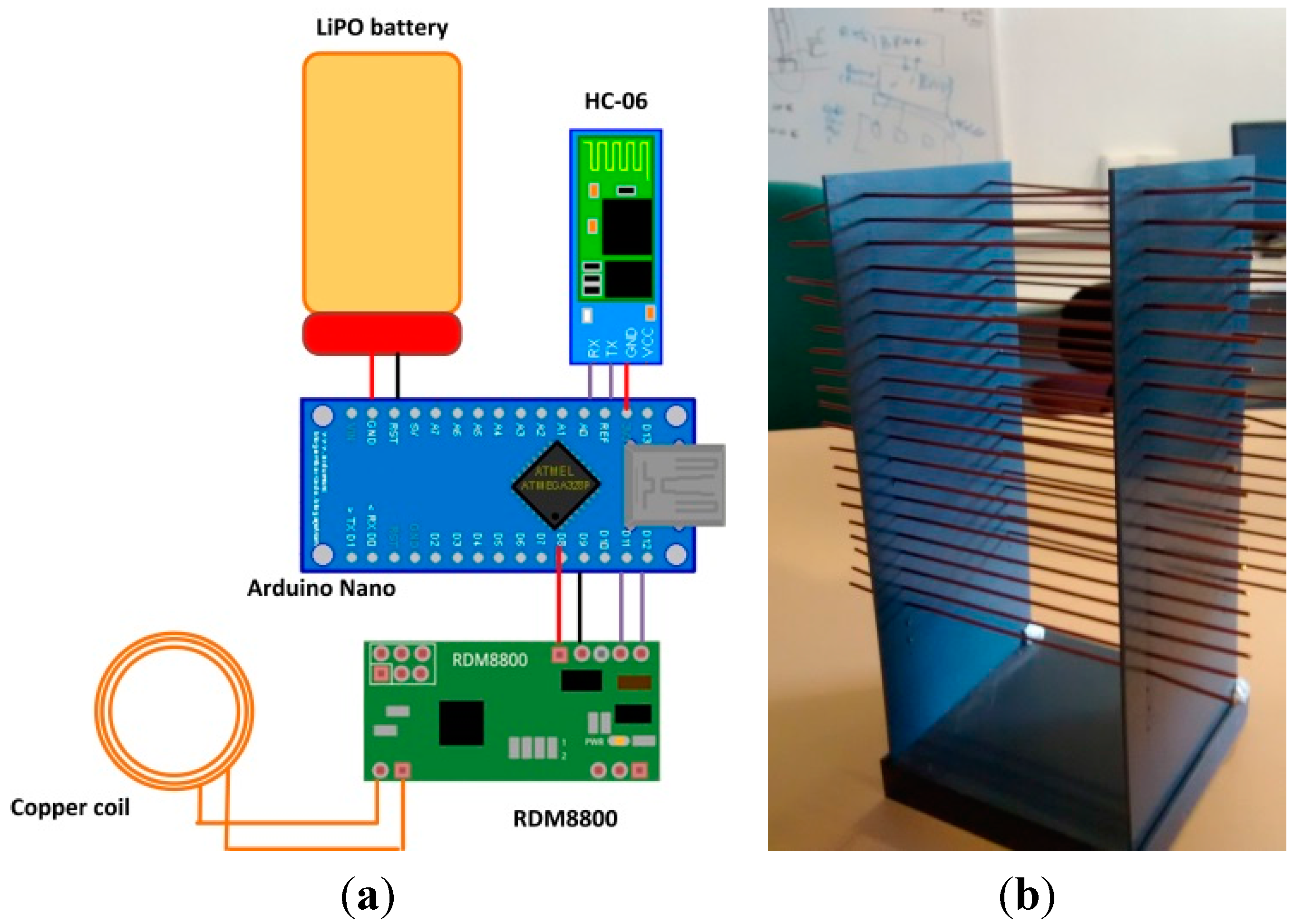
4.1. System Implementation

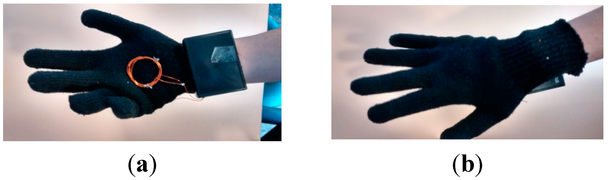
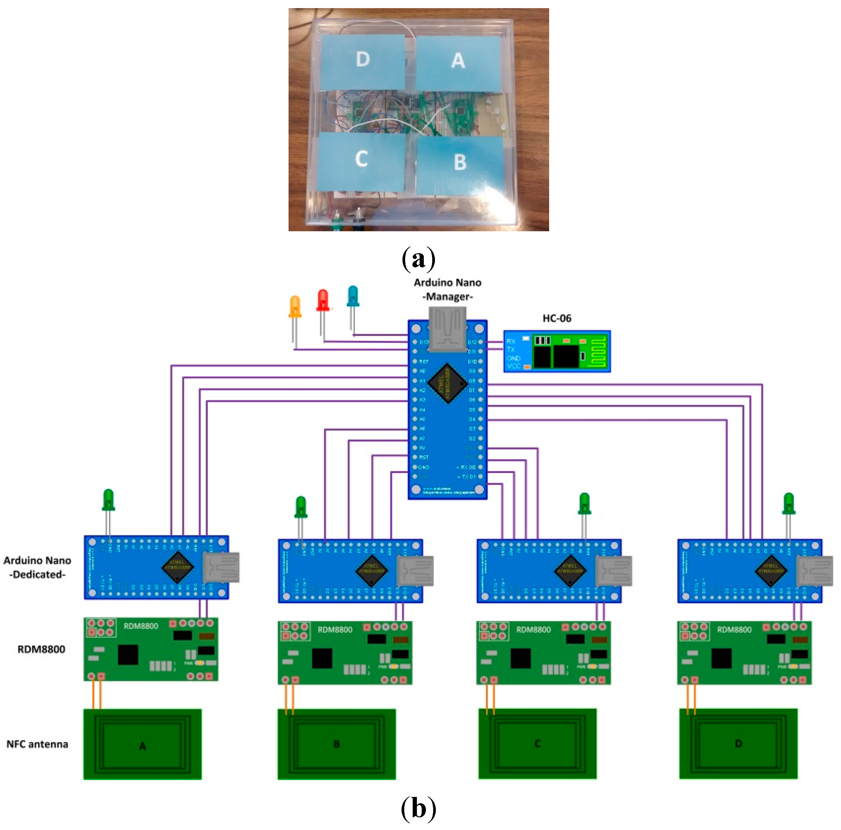
- The LiPO battery has a capacity of 850 mAh and 3.7 V. As the total current consumption of the glove is 140 mA, the glove has the capacity to operate for about 6 h;
- The galvanized copper coil acts as an inductive antenna, resonant at NFC frequency (13.56 MHz);
- The RDM8800 NFC chip receives physical signals from the antenna, and produces a data frame encapsulating, among other fields, the identifier of the tagged cybernetic device that is in contact with the glove. The output interface is UART-serial type (at 9600 bauds);
- The Arduino Nano platform receives data from RDM8800 by UART and extracts the tagged cybernetic device’s identifier. Finally, it encapsulates the identifier in an application protocol message and transmits the message by a second UART at 19,200 bauds;
- The HC-06 Bluetooth slave module receives data by UART at 19,200 bauds and transmits them through a Bluetooth 3.0 interface;
- The table’s LEDs are used as actuators to notify the user of different types of events.

- Five points were selected in height: 0 cm, 1 cm, 1.5 cm, 1.8 cm and 2 cm;
- For each point in height, a set of 10 measurements were made. The probability of correct reading for each point was calculated by means of Laplace definition Equation (1):
- The second step was repeated ten times, obtaining ten different values of the correct reading probability for each point in height. Figure 5 shows the clouds of points obtained, along with a piecewise linear fit (blue line) obtained by minimizing the mean square error. The bubble size indicates the number of times a given value has occurred.

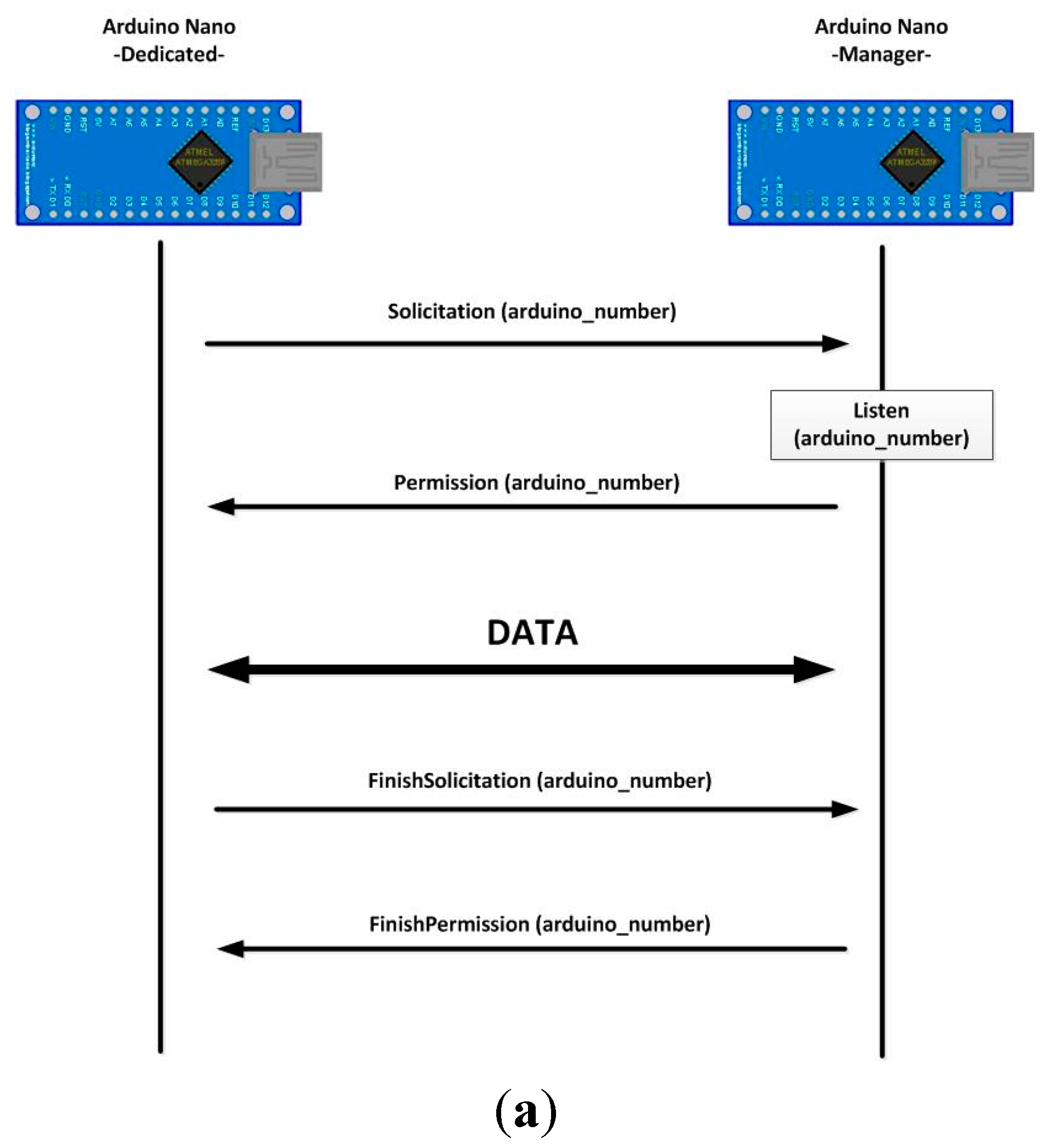
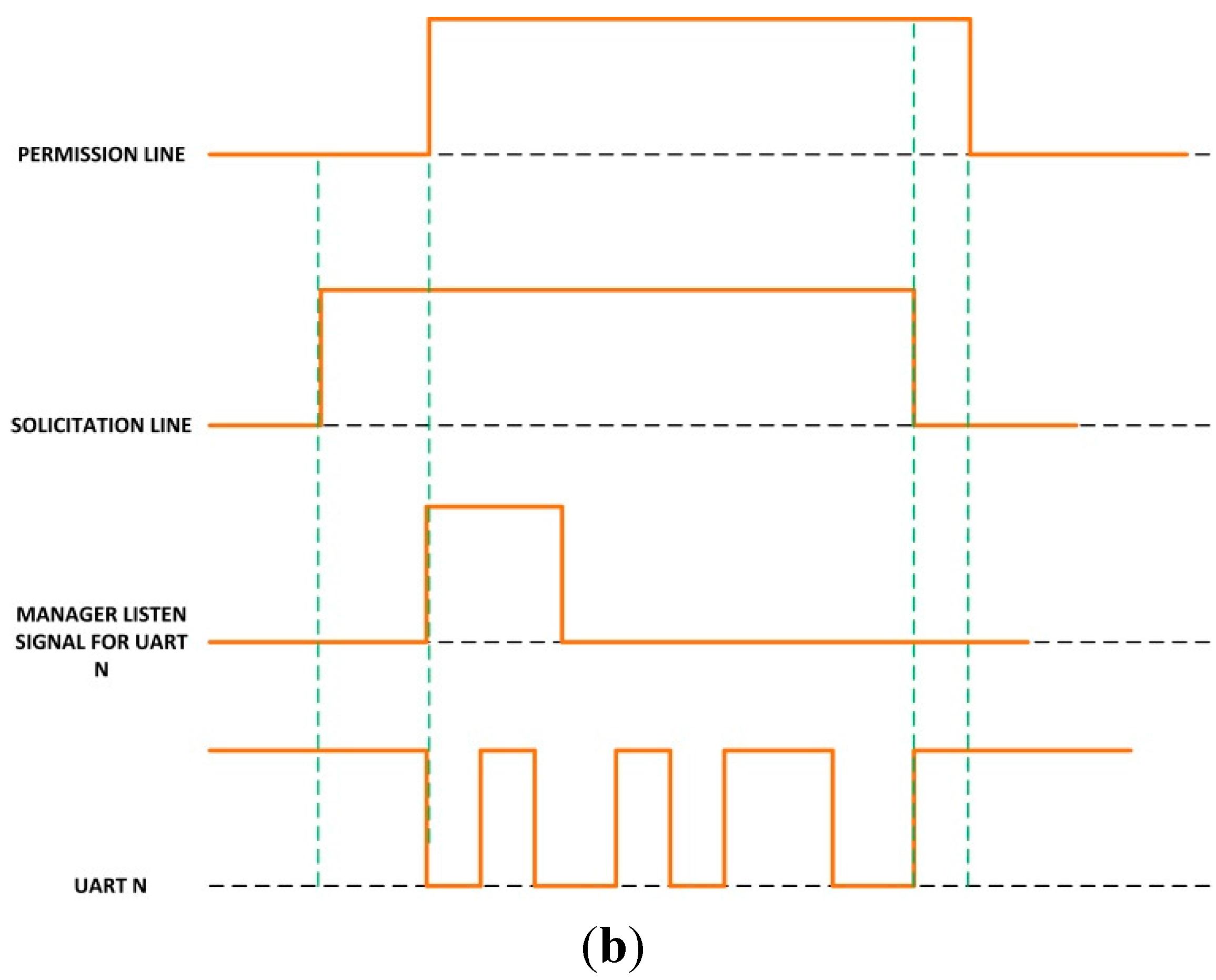
- When a dedicated microcontroller wants to transmit data using the Bluetooth module connected to the manager unit, it sets the solicitation line to high value;
- The manager unit recognizes this signal change and checks whether or not the Bluetooth module is in use. If it is not, it clears the Bluetooth buffers and deletes old transitions. It also sets the permission line to high value to indicate that it is expecting Bluetooth connections;
- When the dedicated microcontroller detects a high level in the permission line, it starts the data transmission. At the end of the transmission, it also sets the solicitation line to low level;
- Finally, when the solicitation line changes to low level, the manager microcontroller also sets the permission line to low level again.


- In the header line, we must indicate the message type: Device Advertisement;
- In the first line of the body, we must place the identification of the new device, followed by a blank space and (optionally) an alias which will appear on the HMI;
- Then, an empty line indicates the beginning of the list of events the device can generate. In each line, first the event code must be placed (see Section 4.2). Later, optionally and separated by a blank space, a description of the event including its parameters, meaning or any other information can be incorporated;
- A new empty line indicates the end of the list of events, and the beginning of the list of actions the device can execute. The list format is the same as in the previous case;
- The message ends with an empty line.
- In the header line, we must indicate the message type: Event;
- In the first line of the body, we must place the identification of the device which notifies the event;
- In the second line the event code (see Section 4.2) must be placed first. Then, after a blank space, it is possible to place as many parameters as required in the event, following the format “parameter = value” and separated from each other by semicolons. The carriage return marks the end of the parameter list;
- The message ends with an empty line.
4.2. Process Model
| Operation | Source | Description |
|---|---|---|
| LED_ON | Cybernetic Table | Turns on the LED specified in the identification parameter. If durationTime value is not included, LED remains on indefinitely. Otherwise, LED is on during durationTime seconds. If the LED is already on, nothing happens. |
| LED_OFF | Cybernetic Table | Turns off the LED specified in the identification parameter. If durationTime value is not included, LED remains off indefinitely. Otherwise, LED is off during durationTime seconds. If the LED is already off, nothing happens. |
| TAG_PUSH_GLOVE | Cybernetic Glove | Turns on the glove’s NFC interface. If any parameter is included, the operation finishes when any NFC tag is read. If durationTime value is specified NFC interface stays on during durationTime seconds. If identification parameter is included, NFC interface stays on until the tag with the specified ID is read. It is possible to combine durationTime and identification value to obtain more complex behaviors. |
| TAG_PUSH_TABLE | Cybernetic Table | Turns on the table’s NFC interface associated with activeZone area. If any parameter is included, operation finishes when any NFC tag is read. If durationTime value is specified NFC interface stays on during durationTime seconds. If identification parameter is included, NFC interface stays on until the tag with the specified ID is read. It is possible to combine durationTime and identification value to obtain more complex behaviors. |
| TAG_POP_GLOVE | Cybernetic Glove | Turns off the glove’s NFC interface. If any parameter is included, operation finishes when the NFC tag that is being read is withdrawn or if there is none, immediately. If durationTime value is specified NFC interface stays on during durationTime seconds and then turned off. |
| TAG_POP_TABLE | Cybernetic Table | Turns off the table’s NFC interface associated with activeZone area. If any parameter is included, operation finishes when the NFC tag which is being read is withdrawn, or, if there is none, immediately. If durationTime value is specified NFC interface stays on during durationTime seconds and then turned off. |
| SHOW_MESSAGE | Visualization platform | Shows on visualization platform a pop-up window, where the content of message value is printed. |
| Event | Source | Description |
|---|---|---|
| TAG_PUSH_GLOVE | Cybernetic Glove | This event is triggered when an NFC tag is detected by the cybernetic glove. In identification parameter, the read tag’s ID must be indicated. |
| TAG_PUSH_TABLE | Cybernetic Table | This event is triggered when one NFC tag is detected by the cybernetic table. The activeZone value includes the reader area where the tag has been detected and in identification parameter, the tag’s ID must be indicated. |
| TAG_POP_GLOVE | Cybernetic Glove | This event is triggered when an NFC tag previously detected by the cybernetic glove is withdrawn. In identification parameter, the withdrawn tag’s ID must be indicated. |
| TAG_POP_TABLE | Cybernetic Table | This event is triggered when one NFC tag previously detected by the cybernetic table is withdrawn. The activeZone value includes the reader area where the tag has been withdrawn and in identification parameter, the withdrawn tag’s ID must be indicated. |
| WORKFLOW_START | Execution engine | This event is triggered when a workflow has been recovered by a user and must start. In identification parameter the workflow ID is indicated. |
| WORKFLOW_END | Execution engine | This event is triggered when a workflow has finished successfully. In identification parameter the workflow ID is indicated. |
| ACTIVITY_COMPLETE | Execution engine | This event is triggered when an activity has finished successfully. In identification parameter the activity ID is indicated and, in parentIdentification, the workflow’s ID to which this activity belongs is included. This event will allow not only store traces of atomic operations and activities. |
| ACTIVITY_FAIL | Execution engine | This event is triggered when an activity has failed. In identification parameter the activity ID is indicated and, in parentIdentification, the workflow’s ID to which this activity belongs is included. |
| WORKFLOW_FAIL | Execution engine | This event is triggered when a workflow has failed. In identification parameter the workflow ID is indicated. |
| WORKFLOW_NEW | Execution engine | This event is triggered when a new workflow is created in the execution engine. In the workflow parameter, the new workflow is codified using bytes. |

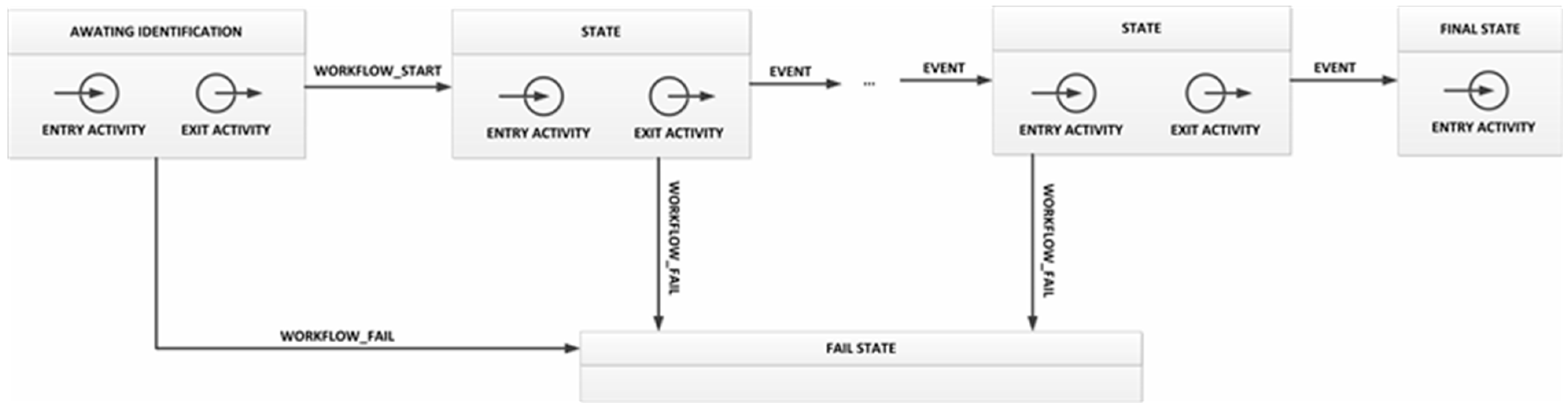
- Entry activity: first a SHOW_MESSAGE operation must be executed in order to ask users to identify themselves. Then, a TAG_PUSH_GLOVE operation turns on the glove’s NFC interface, which is not deactivated until the users again uses his ID to close the state;
- As the execution engine subscribes to the corresponding topic (see Section 4.3), it will receive information on the user’s ID. The execution engine checks whether the workflow owner user is the same user that was identified. If so, a WORKFLOW_START event is generated;
- Transition: the workflow will execute the transition toward the next state when a WORKFLOW_START event is received;
- Exit activity: this activity is made up of only one SHOW_MESSAGE operation, to indicate to users that the workflow verification has started.
4.3. System Deployment
| Device | Configuration |
|---|---|
| Cybernetic glove | All the events generated in the glove are directly published without been processed. |
| Cybernetic table | The TAG_PUSH_TABLE event turns on one green LED. The TAG_POP_TABLE event turns off the same green LED. The WORKFLOW_START event turns on an orange LED. Both TAG_PUSH_TABLE and TAG_POP_TABLE events are also published. The WORKFLOW_END event turns on a blue LED for 10 seconds, and the WORKFLOW_FAIL does the same with a red LED. |
| Visualization platform | It is subscribed to all the topics that are used to update the platform. |
| Execution engine | It is subscribed to all the topics that are used to update the workflow, and also to publish all the events it generates. |
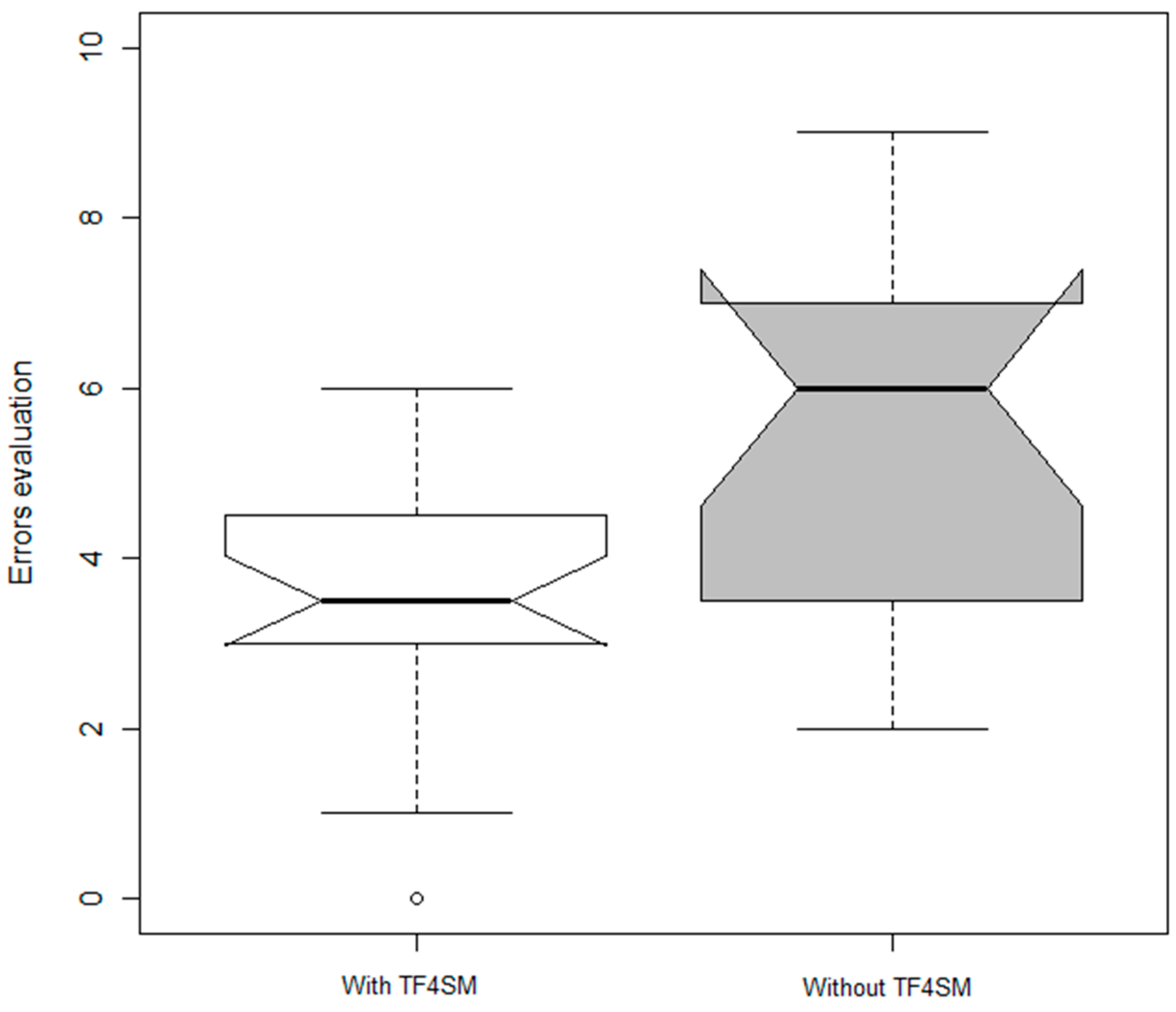
5. Experimental Validation
- Would the time response to inefficiencies improve by deploying a system based on our TF4SM in companies?
- Is it possible to reduce the number of inefficiencies in productive processes using a TF4SM-based system?
6. Results
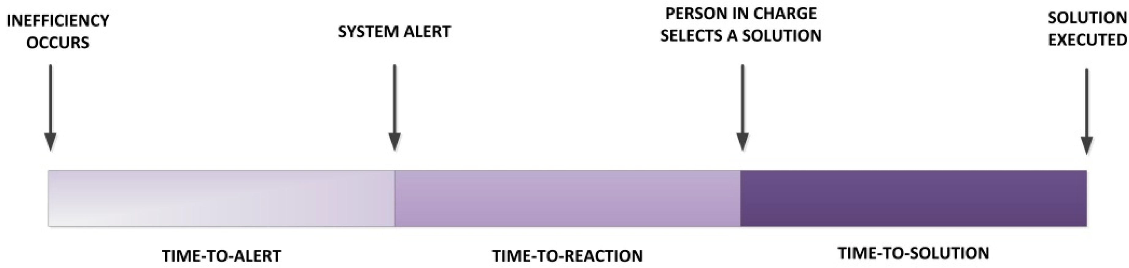
| System Employed | Time-to-Alert Time | Time-to-Reaction Time |
|---|---|---|
| Tag-based system | Less than 10 s | Between 1 and 3 min |
| TF4SM | Immediate | Less than 30 s |

7. Conclusions
Author Contributions
Conflicts of Interest
References
- European Project: Real-time Monitoring and Optimization of Resource Efficiency in Integrated Processing Plants (FP7-NMP-2013-SMALL-7), Supported by the European Commission. Available online: http://cordis.europa.eu/project/rcn/110822_en.html (accessed on 26 August 2015).
- Woodall, W.H.; Montgomery, D.C. Some current directions in the theory and application of statistical process monitoring. J. Qual. Technol. 2014, 46, 78–94. [Google Scholar]
- Weske, M. Business Process Management: Concepts, Languages, Architectures; Springer Science & Business Media: Berlin, Germany, 2012. [Google Scholar]
- Condea, C.; Thiesse, F.; Fleisch, E. RFID-enabled shelf replenishment with backroom monitoring in retail stores. Decis. Support Syst. 2012, 52, 839–849. [Google Scholar] [CrossRef]
- Cook, D.; Das, S. Smart Environments: Technology, Protocols and Applications; John Wiley & Sons: Hoboken, NJ, USA, 2004. [Google Scholar]
- Gungor, V.C.; Hancke, G.P. Industrial wireless sensor networks: Challenges, design principles, and technical approaches. IEEE Trans. Ind. Electron. 2009, 56, 4258–4265. [Google Scholar] [CrossRef]
- Al Agha, K. Which wireless technology for industrial wireless sensor networks? The development of OCARI technology. IEEE Trans. Ind. Electron. 2009, 56, 4266–4278. [Google Scholar] [CrossRef]
- Cao, H.; Folan, P.; Mascolo, J.; Browne, J. RFID in product lifecycle management: A case in the automotive industry. Int. J. Comput. Integr. Manuf. 2009, 22, 616–637. [Google Scholar] [CrossRef]
- Dai, Q.Y.; Zhong, R.Y.; Zhou, K.; Jiang, Z.Y. A RFID-enabled Real-Time Manufacturing Hardware Platform for Discrete Industry. In Proceeding of the 6th CIRP-Sponsored International Conference on Digital Enterprise Technology, Hong Kong, China, 14–16 December 2010; Springer-Verlag: Berlin, Heidelberg, 2010; Volume 66, pp. 1743–1750. [Google Scholar]
- Banks, J.; Pachano, M.A.; Thompson, L.G.; Hanny, D. RFID Applied; John Wiley & Sons: Hoboken, NJ, USA, 2007. [Google Scholar]
- Ilie-Zudor, E.; Kemény, Z.; van Blommestein, F.; Monostori, L.; van der Meulen, A. A survey of applications and requirements of unique identification systems and RFID techniques. Comput. Ind. 2010, 62, 227–252. [Google Scholar] [CrossRef]
- Dai, Q.; Zhong, R.; Huang, G.Q.; Qu, T.; Zhang, T.; Luo, T.Y. Radio frequency identification-enabled real-time manufacturing execution system: A case study in an automotive part manufacturer. Int. J. Comput. Integr. Manuf. 2012, 25, 51–65. [Google Scholar] [CrossRef]
- Hur, S.M.; Jeong, S.; Suh, S.H. An experimental approach to RFID system performance prediction model. Int. J. Comput. Integr. Manuf. 2009, 22, 686–697. [Google Scholar] [CrossRef]
- Bendavid, Y.; Cassivi, L. Bridging the gap between RFID/EPC concepts, technological requirements and supply chain e-business processes. J. Theor. Appl. Electron. Commer. Res. 2010, 5, 1–16. [Google Scholar] [CrossRef]
- Lee, E.A. Cyber-physical systems—Are computing foundations adequate? In NSF Workshop on Cyber-Physical Systems: Research Motivation, Techniques and Roadmap, Austin, TX, USA, 16–17 October 2006.
- National Institute of Standards and Technology. Cyber-Physical Systems Homepage. Available online: http://www.nist.gov/cps/ (accessed on 19 November 2015).
- National Institute of Standards and Technology. CPS Public Working Group Presentation. Available online: http://www.nist.gov/el/upload/CPS-PWG-Kickoff-Webinar-Presentation-FINAL.PDF (accessed on 26 October 2015).
- Wang, Y.; Vuran, M.C.; Goddard, S. Cyber-physical systems in industrial process control. ACM SIGBED Rev. 2008, 5. [Google Scholar] [CrossRef]
- Wu, F.; Kao, Y.; Tseng, Y. From wireless sensor networks towards cyber physical systems. Pervasive Mob. Comput. 2011, 7, 397–413. [Google Scholar] [CrossRef]
- Li, S. Industrial wireless sensor networks. Int. J. Distrib. Sensor Netw. 2014, 2014, 1–2. [Google Scholar] [CrossRef]
- Software Im Maschinenbau-Lästiges Anhängsel Oder Chance Zur Marktführerschaft? Available online: http://www.software-kompetenz.de/servlet/is/21700/StetterSW_im_Maschinenbau.pdf?command=downloadContent&filename=Stetter-SW_im_Maschinenbau.pdf (accessed on 26 October 2015).
- Automation Expenditures for Discrete Industries. Available online: http://www.arcweb.com/market-studies/pages/automation-systems-for-discrete-industries.aspx (accessed on 26 October 2015).
- InternationalElectrotechnical Commission. International Standard IEC 62264-1: Enterprise-Control System Integration Part 1: Models and Terminology; IEC: Geneva, Switzerland, 2003. [Google Scholar]
- Hussain, T.; Frey, G. Migration of a PLC controller to an IEC 61499 compliant distributed control system: Hands-on experiences. In Proceedings of the IEEE International Conference on Robotics and Automation, Barcelona, Spain, 18–22 April 2005; pp. 3984–3989.
- OPC 2.1 Standard. Available online: https://opcfoundation.org/ (accessed on 26 October 2015).
- Davenport, T.H. Process Innovation: Reengineering Work through Information Technology; Harvard Business Press: Boston, MA, USA, 2013. [Google Scholar]
- Vyatkin, V. Software engineering in industrial automation: State-of-the-art review. IEEE Trans. Ind. Inform. 2013, 9, 1234–1249. [Google Scholar] [CrossRef]
- Thramboulidis, K.; Zoupas, A. Real-time Java in control and automation: A model driven development approach. In Proceedings of the 10th IEEE Conference on Emerging Technologies and Factory Automation, Catania, Italy, 19–22 September 2005; pp. 8–46.
- Jimenez, M.; Rosique, F.; Sanchez, P.; Alvarez, B.; Iborra, A. Habitation: A domain-specific language for home automation. IEEE Softw. 2009, 26, 30–38. [Google Scholar] [CrossRef]
- Alcarria, R.; Robles, T.; Morales, A.; López-de-Ipiña, D.; Aguilera, U. Enabling flexible and continuous capability invocation in mobile prosumer environments. Sensors 2012, 12, 8930–8954. [Google Scholar] [CrossRef] [PubMed]
- Erl, T. Service-Oriented Architecture: Concepts, Technology, and Design; Prentice Hall PTR: Upper Saddle River, NJ, USA, 2005. [Google Scholar]
- Jammes, F.; Smit, H. Service-oriented paradigms in industrial automation. IEEE Trans. Ind. Inform. 2005, 1, 62–70. [Google Scholar] [CrossRef]
- Kirova, V.; Kirby, N.; Kothari, D.; Childress, G. Effective requirements traceability: Models, tools, and practices. Bell Labs Tech. J. 2008, 12, 143–157. [Google Scholar] [CrossRef]
- Moe, T. Perspectives on traceability in food manufacture. Trend Food Sci. Technol. 1998, 9, 211–214. [Google Scholar] [CrossRef]
- Muldoon, M. Integrating information systems to improve competitiveness. Brew. Distill. Int. 1992, 23, 13–14. [Google Scholar]
- Wall, B. Golden gains from weightwatching. Potato Bus. World 1995, 3, 34–37. [Google Scholar]
- Li, M.; Qian, J.P.; Yang, X.T.; Sun, C.H.; Ji, Z.T. A PDA-based record-keeping and decision-support system for traceability in cucumber production. Comput. Electron. Agric. 2010, 70, 69–77. [Google Scholar] [CrossRef]
- Seine, K.; Kuwabara, S.; Mikami, S.; Takahashi, Y.; Yoshikawa, M.; Narumi, H.; Koganezaki, K.; Wakabayashi, T.; Nagano, A. development of the traceability system which secures the safety of fishery products using the QR code and a digital signature. In Proceedings of the OCEANS’04. MTTS/IEEE TECHNO-OCEAN ’04, Kobe, Japan, 9–12 November 2004; pp. 476–481.
- Hsu, Y.-C.; Chen, A.-P.; Wang, C.-H. A RFID-enabled traceability system for the supply chain of live fish. In Proceedings of the IEEE International Conference on Automation and Logistics, Qingdao, China, 1–3 September 2008; pp. 81–86.
- Gandino, F.; Montrucchio, B.; Rebaudengo, M.; Sanchez, E.R. On improving automation by integrating RFID in the traceability management of the Agri-food sector. IEEE Trans. Ind. Electron. 2009, 56, 2357–2365. [Google Scholar] [CrossRef]
- Das, S.K.; Cook, D.J. Agent based health monitoring in smart homes. In Proceedings of the International Conference on Smart Homes and Health Telematics (ICOST), Singapore, 15–17 September 2004; pp. 3–14.
- Das, S.K.; Cook, D.J.; Battacharya, A.; Heierman, E.O., III; Lin, T-Y. The role of prediction algorithms in the MavHome smart home architecture. IEEE Wirel. Commun. 2002, 9, 77–84. [Google Scholar] [CrossRef]
- Le Gal, C.; Martin, J.; Lux, A.; Crowley, J.L. Smart office: Design of an intelligent environment. IEEE Intell. Syst. 2001, 4, 60–66. [Google Scholar] [CrossRef]
- Lesser, V.; Atighetchi, M.; Benyo, B.; Horling, B.; Raja, A.; Wagner, T.; Xuan, P.; Zhang, S. The intelligent home testbed. In Proceedings of the Autonomy Control Software Workshop, Seattle, WA, USA, 29 January 1999.
- Misra, A.; Das, S.K. Location estimation (determination and prediction) techniques in smart environments. In Smart Environments: Technology, Protocols and Applications; Cook, D., Das, S., Eds.; John Wiley & Sons: Hoboken, NJ, USA, 2005; pp. 193–228. [Google Scholar]
- Nixon, P.; Lacey, G.; Dobson, S. (Eds.) Managing Interactions in Smart Environments: 1st International Workshop on Managing Interactions in Smart Environments (MANSE’99), Dublin, December 1999; Springer-Verlag: London, UK, 2000.
- Derler, P.; Lee, E.A.; Vincentelli, A.S. Modeling cyber-physical systems. Proc. IEEE 2012, 100, 13–28. [Google Scholar] [CrossRef]
- Lee, E.A. The past, present and future of cyber-physical systems: A focus on models. Sensors 2015, 15, 4837–4869. [Google Scholar] [CrossRef] [PubMed]
- Kelepouris, T.; Pramatari, K.; Doukidis, G. RFID-enabled traceability in the food supply chain. Ind. Manag. Data Syst. 2007, 107, 183–200. [Google Scholar] [CrossRef]
- Riedl, M.; Zipper, H.; Meier, M.; Diedrich, C. Cyber-physical systems alter automation architectures. Annu. Rev. Control 2014, 38, 123–133. [Google Scholar] [CrossRef]
- Colombo, A.; Karnouskos, S.; Bangemann, T. Towards the Next Generation of Industrial Cyber-Physical Systems. In Industrial Cloud-based Cyber-physical Systems; Colombo, A., Bangemann, T., Karnouskos, S., Delsing, J., Stluka, P., Harrison, R., Jammes, F., Lastra, J.L., Eds.; Springer International Publishing: Geneva, Switzerland, 2014; pp. 1–22. [Google Scholar]
- Al-Anbagi, I.; Erol-Kantarci, M.; Mouftah, H.T. A reliable IEEE 802.15. 4 model for cyber physical power grid monitoring systems. IEEE Trans. Emerg. Top. Comput. 2013, 1, 258–272. [Google Scholar] [CrossRef]
- Blackburn, M.; Denno, P. Virtual design and verification of cyber-physical systems: Industrial process plant design. Proced. Comput. Sci. 2014, 28, 883–890. [Google Scholar] [CrossRef]
- Gupta, I.; Kaur, R. Realization of automated industrial pollution control system using LabVIEW. Int. J. Res. 2014, 1, 834–838. [Google Scholar]
- Suender, C.; Wenger, M.; Hanni, C.; Gosetti, I.; Steininger, H.; Fritsche, J. Transformation of existing IEC 61131-3 automation projects into control logic according to IEC 61499. In Proceedings of the IEEE International Conference on Emerging Technologies and Factory Automation, Hamburg, Germany, 15–18 September 2008; pp. 369–376.
- Wenger, M.; Zoitl, A.; Sunder, C.; Steininger, H. Transformation of IEC 61131-3 to IEC 61499 based on a model driven development approach. In Proceedings of the 7th IEEE International Conference on Industrial Informatics, Cardiff, UK, 23–26 June 2009; Volume 1, pp. 715–720.
- Von Krosigk, H. Functional safety in the field of industrial automation. The influence of IEC 61508 on the improvement of safety-related control systems. Comput. Control Eng. J. 2000, 11, 13–18. [Google Scholar] [CrossRef]
- Ito, M. Smart Furniture: Improvising ubiquitous hot-spot environment. In Proceedings of the 23rd International Conference on Distributed Computing Systems Workshops, Providence, RI, USA, 19–22 May 2003; pp. 248–253.
- Tokuda, H.; Takashio, K.; Nakazawa, J.; Matsumiya, K.; Ito, M.; Saito, M. SF2: Smart furniture for creating ubiquitous applications. In Proceedings of the International Symposium on Applications and the Internet, Tokyo, Japan, 26–30 January 2004; pp. 423–429.
- Hagale, A.R.; Kelley, J.E.; Rozich, R. RFID Smart Office Chair. U.S. Patent 6,964,370, 15 November 2005. [Google Scholar]
- Fishkin, K.P.; Philipose, M.; Rea, A. Hands-on RFID: Wireless wearables for detecting use of objects. In Proceedings of the 9th International Symposium on Wearable Computers, Osaka, Japan, 18–21 October 2005; pp. 38–43.
- Fujitsu’s Smart Glove. Available online: http://www.qore.com/articulos/17335/Fujitsu-desarrolla-un-guante-de-realidad-aumentada (accessed on 26 October 2015).
- Kirstein, T.; Cottet, D.; Grzyb, J.; Tröster, G. Textiles for signal transmission in wearables. In Proceedings of the ACM of First Workshop on Electronic Textiles (MAMSET 2002), San Jose, CA, USA, 4 October 2002.
- Marculescu, D. Electronic textiles: A platform for pervasive computing. IEEE Proc. 2003, 91, 1995–2018. [Google Scholar] [CrossRef]
- Giochi SmartPoker. Available online: http://www.gtigaming.com/en/product-service/smartpoker-2/ (accessed on 18 July 2015).
- Argos Smart Clinical Cupboard. Available online: http://sicolareshigia.com/armario-de-control-de-stock/ (accessed on 18 July 2015).
- Palex Smart Clinical Cupboard. Available online: http://www.europapress.es/extremadura/salud-00924/noticia-infanta-cristina-badajoz-acogera-forma-piloto-armario-inteligente-suministro-material-sanitario-20150225143205.html (accessed on 26 October 2015).
- Izco Smart Clinical Cupboard. Available online: http://www.farodevigo.es/economia/2014/09/28/viguesa-izco-lanza-fabricacion-armarios/1102202.html (accessed on 26 October 2015).
- SATO’s VINICITY Technology. Available online: http://www.satovicinity.com/sp/products_magellan_pjm_rfid_smart_readers.asp (accessed on 26 October 2015).
- Wolf, M. High-Performance Embedded Computing: Applications in Cyber-Physical Systems and Mobile Computing, 2nd ed.; Morgan Kaufmann: Burlington, MA, USA, 2014. [Google Scholar]
- Kortuem, G.; Kawsar, F.; Fitton, D.; Sundramoorthy, V. Smart objects as building blocks for the internet of things. IEEE Internet Comput. 2010, 14, 44–51. [Google Scholar] [CrossRef]
- Osaka, K.; Takagi, T.; Yamazaki, K.; Takahashi, O. An efficient and secure RFID security method with ownership transfer. In Proceedings of the International Conference on Computational Intelligence and Security, Guangzhou, China, 3–6 November 2006; Volume 2, pp. 1090–1095.
- Schmidt, A. Implicit human computer interaction through context. Pers. Technol. 2000, 4, 191–199. [Google Scholar] [CrossRef]
- Fouquet, F. A dynamic component model for cyber physical systems. In Proceedings of the 15th ACM SIGSOFT Symposium on Component Based Software Engineering, Bertinoro, Italy, 25–28 June 2012; pp. 135–144.
- Kim, K.; Panganamala, R. Cyber-physical systems: A perspective at the centennial. IEEE Proc. 2012, 100, 1287–1308. [Google Scholar] [CrossRef]
- Morales, A.; Robles, T.; Alcarria, R.; Cedeño, E. On the support of scientific workflows over Pub/Sub brokers. Sensors 2013, 13, 10954–10980. [Google Scholar] [CrossRef] [PubMed]
- Fortino, G.; Guerrieri, A.; Russo, W. Agent-oriented smart objects development. In Proceedings of the IEEE 16th International Conference on Computer Supported Cooperative Work in Design, Wuhan, China, 23–25 May 2012; pp. 907–912.
- RDM 8800 Datasheet. Available online: ftp://imall.iteadstudio.com/Modules/IM131218001/DS_IM131218001.pdf (accessed on 26 October 2015).
- Tang, L. Trustworthiness analysis of sensor data in cyber-physical systems. J. Comput. Syst. Sci. 2013, 79, 383–401. [Google Scholar] [CrossRef]
- Schmitt, C. TinyIPFIX: An efficient application protocol for data exchange in cyber physical systems. Comput. Commun. 2014. [Google Scholar] [CrossRef]
- Zuo, X.; Tan, W.; Lin, H. Cigarette production scheduling by combining workflow model and immune algorithm. IEEE Trans. Autom. Sci. Eng. 2014, 11, 251–264. [Google Scholar] [CrossRef]
© 2015 by the authors; licensee MDPI, Basel, Switzerland. This article is an open access article distributed under the terms and conditions of the Creative Commons Attribution license (http://creativecommons.org/licenses/by/4.0/).
Share and Cite
Bordel Sánchez, B.; Alcarria, R.; Martín, D.; Robles, T. TF4SM: A Framework for Developing Traceability Solutions in Small Manufacturing Companies. Sensors 2015, 15, 29478-29510. https://doi.org/10.3390/s151129478
Bordel Sánchez B, Alcarria R, Martín D, Robles T. TF4SM: A Framework for Developing Traceability Solutions in Small Manufacturing Companies. Sensors. 2015; 15(11):29478-29510. https://doi.org/10.3390/s151129478
Chicago/Turabian StyleBordel Sánchez, Borja, Ramón Alcarria, Diego Martín, and Tomás Robles. 2015. "TF4SM: A Framework for Developing Traceability Solutions in Small Manufacturing Companies" Sensors 15, no. 11: 29478-29510. https://doi.org/10.3390/s151129478