A New Adaptive Self-Tuning Fourier Coefficients Algorithm for Periodic Torque Ripple Minimization in Permanent Magnet Synchronous Motors (PMSM)


 and
and 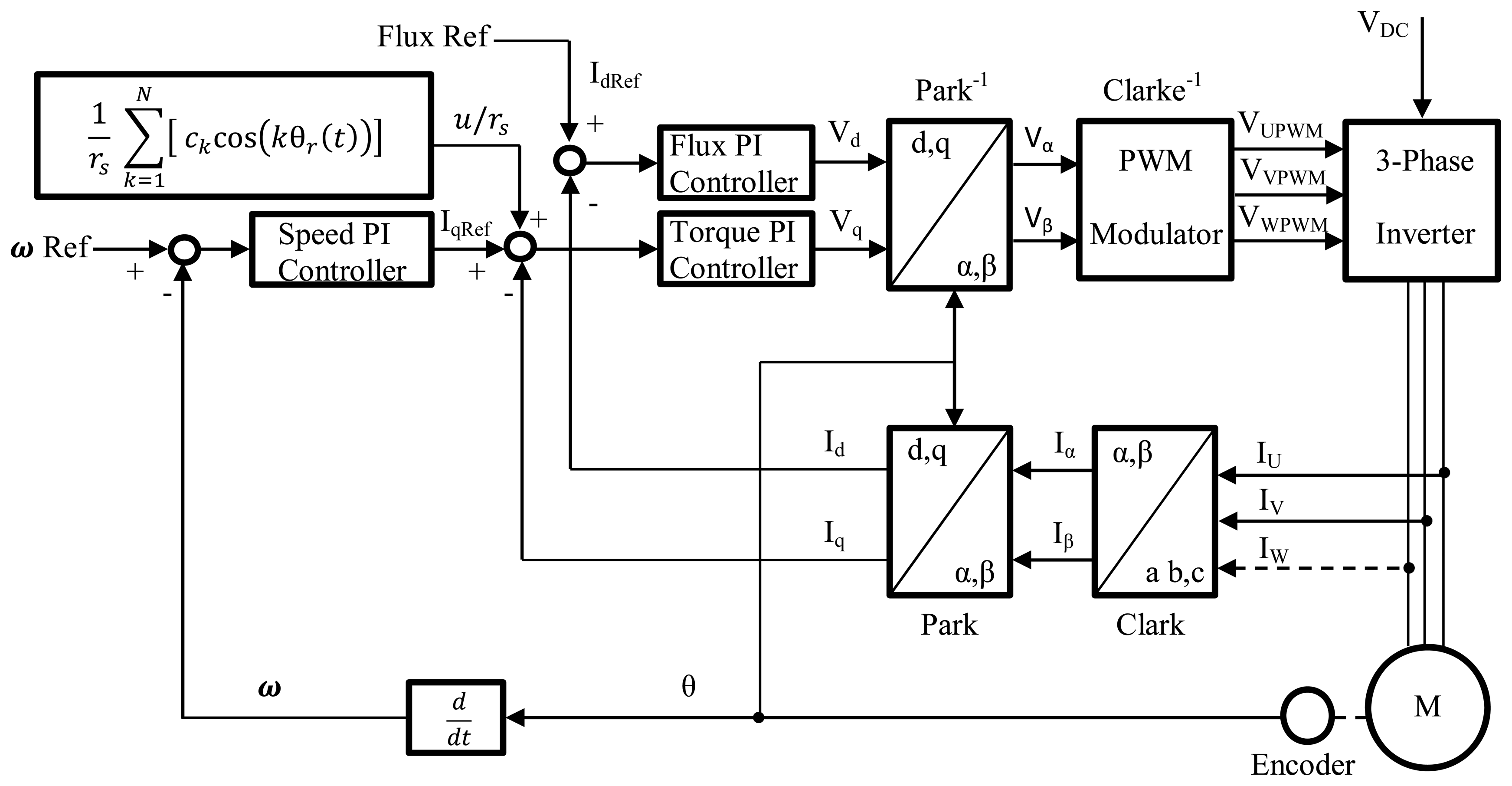
Abstract
: Torque ripple occurs in Permanent Magnet Synchronous Motors (PMSMs) due to the non-sinusoidal flux density distribution around the air-gap and variable magnetic reluctance of the air-gap due to the stator slots distribution. These torque ripples change periodically with rotor position and are apparent as speed variations, which degrade the PMSM drive performance, particularly at low speeds, because of low inertial filtering. In this paper, a new self-tuning algorithm is developed for determining the Fourier Series Controller coefficients with the aim of reducing the torque ripple in a PMSM, thus allowing for a smoother operation. This algorithm adjusts the controller parameters based on the component's harmonic distortion in time domain of the compensation signal. Experimental evaluation is performed on a DSP-controlled PMSM evaluation platform. Test results obtained validate the effectiveness of the proposed self-tuning algorithm, with the Fourier series expansion scheme, in reducing the torque ripple.1. Introduction
The Permanent Magnet Synchronous Motor (PMSM) market is growing more rapidly when compared to traditional competitors because of lower cost, as well as higher efficiency and reliability. For the sake of energy savings and environmental performance, PMSMs also feature one of the highest torque to loss ratios. These motors are widely used in fast dynamic positioning systems and machine-tool components [1,2]. The main disadvantage of PMSMs is the non-uniformity in the developed torque, known as “torque ripple” [3]. Torque ripple generates speed oscillations which cause system performance deterioration and in machine-tool applications, it can leave visible patterns on high precision machined surfaces [4]. Under the assumption of pure sinusoidal back electromagnetic force (EMF), the conventional Field Oriented Control (FOC) applies constant current references in the synchronous reference frame to produce a constant torque. However, depending on the magnet shape and how well the windings are manufactured, the back-EMF has in practice very different waveforms, which range from almost sinusoidal to trapezoidal. Torque ripple occurs in PMSMs due to non-sinusoidal flux density distribution around the air-gap and the variable magnetic reluctance of the air-gap due to stator slots distribution. These torque ripples change periodically with rotor position and are apparent as speed variations, which degrades the PMSM drive performance, particularly at low speeds because of low inertial filtering [5].
In order to improve the performance of PMSMs and increase its market share, the suppression of the pulsating torque has received much attention in recent years [6–17]. These torque ripple reduction techniques can be divided into two groups: one focusing on the improvement of motor design and the other emphasizing the use of active control of stator current excitation. From the motor design point of view, skewing the stator lamination stacks or rotor magnets, arranging proper winding distributions and incorporating other motor design features reduces cogging torque partially, but does not completely eliminate it. Moreover, special machine design processes add addition complexity to the production process, which results in higher machine cost [18].
The second approach, which is of our interest, concentrates on using an additional control effort to compensate for the periodic torque pulsations. Some methods rely on pre-programed stator current excitation to cancel torque harmonics. However, accurate information about the PMSM parameters is required, and a small error or variation in these parameters can produce higher torque ripple due to the open-loop control. As an alternative, closed-loop control algorithms with online estimation of parameters and adaptive control algorithms have been proposed to reduce torque ripple. One possible approach relies on a closed-loop speed regulator to attenuate indirectly torque pulsations since all possible sources of torque ripple are observable from rotor speed, and hence this method has potential for complete torque ripple minimization. Repetitive Control techniques incorporate a sinusoidal control component to deal with periodic torque pulsations [19–23] while Iterative Learning Control (ILC) is implemented in the frequency domain to reduce torque ripple, by means of Fourier series expansion [24–29]. Some recent papers deal with learning control algorithms for Permanent Magnet Step Motors [30–32], by identifying the Fourier coefficients of any truncated approximation and implementing Iterative Learning techniques, providing an experimental comparison for both methods. Adaptive techniques have been proposed based on the spectrum of the torque perturbation using some theoretical developments.
In this paper, a new self-tuning algorithm is developed for determining the Fourier Series Controller coefficients with the aim of reducing the torque ripple in a PMSM, thus allowing for a smoother operation. This algorithm adjusts the controller parameters based on the component's harmonic distortion in the time domain of the compensation signal. The estimated Fourier coefficients are used by a nonlinear controller which achieves accurate and ripple-reduced torque control. Experimental evaluation was performed on a DSP-controlled PMSM evaluation platform and test results obtained verify the effectiveness of proposed self-tuning algorithm, with the Fourier series expansion scheme, in reducing the torque ripple.
This paper is organized as follows: A model of the Permanent Magnet Synchronous Motor is presented in Section 2. The new self-tuning Fourier Coefficient Algorithm is introduced in Section 3. Section 4 describes the experimental setup, and the experimental results are presented in Section 5. Finally, in Section 6 concluding remarks are provided.
2. Model of PMSM
In this section, a standard PMSM model [33] is revised and additional considerations are explained so torque ripple sources are clarified. For a three-phase PMSM, the flux linkages Ψabs related to the mutual and self-inductances Ls and currents i are given as:
In matrix form:
The stator windings voltages uabcs depend on the winding resistance rs and flux linkages Ψabcs:
Rewriting this expression in matrix form:
The stator windings are displaced by 120°, and the flux linkages Ψasm, Ψbsm, Ψcsm established by the permanent magnet, which are periodic functions of θr, are assumed to be sinusoidal with magnitude Ψm:
From Equation (3), assuming Ls is constant:
Defining , we have:
Hence, in Cauchy form, by using :
Incorporating the transient behavior of the mechanical system, where electric torque Te, load torque TL, viscous friction coefficient Bm and inertia moment J are used:
To find the electromagnetic torque developed Te, where WPM is the permanent magnet energy, the co-energy Wc is used:
Therefore, we have the following formula to calculate the electromagnetic torque for the three-phase P -pole permanent-magnet synchronous motors:
Hence:
Using the electrical angular velocity ωr and displacement “θr”, related to mechanical angular velocity and displacement as and , results in the following equation:
Regarding the implicit time reparameterization to express the time functions acceleration and the speed in Equation (14) as functions of the rotor position, the relation rotor position-time is guaranteed to be invertible for the total rotor position (not only for one revolution range), if rotor position is a monotonic function of time like happen for a non-cero angular speed of constant sign.
To control the angular velocity, one regulates the currents fed or voltages applied to the stator windings. To maximize the electromagnetic torque developed, the motor should be fed by a balanced three-phase current set:
Generating an electromagnetic torque:
To produce the specified current, the balanced three-phase voltages are given as:
To simplify the control of PMSM, it is a common practice to transform the equations from three-phase voltages uabcds to the qd0 variables uqd0s for the rotor reference frame [34].
In matrix form, the mathematical model of the PMSM in the rotor reference frame is given as:
The required currents to regulate the angular velocity of PMSM and guarantee balanced operating conditions are given as:
And assuming that inductances are negligible, the applied voltages should be:
2.1. Additional Considerations
In order to understand torque ripple in PMSM we have to reconsider some assumptions from the previous model.
2.1.1. Non-Sinusoidal Flux Linkages
Flux linkages are not perfectly sinusoidal so the electromotive force differs from cosine function and applying cosine currents to the stator windings produces torque ripples. The induced non-cosine electromotive forces eabcs are all assumed to be periodic functions with a peak value Ep [35]:
Since electromagnetic torque is given by:
Using Equation (21), we finally have:
2.1.2. Non-Constant Inductances
From Equation (1), electromotive force can be calculated by:
Without assuming constant Ls:
The second term from Equation (25) produces torque ripple due to inductance angular variations, and it is associated to differences in winding inductances of the stator.
2.1.3. Stator Yoke Reluctance Variations
From a macroscopic viewpoint, the torque produced in a PMSM is given by [35]:
As mentioned before, the first term appears when motor construction causes the winding inductance to vary as a function of position, and third term describes the mutual torque that is used to make the motor shaft turn. Additionally the second term describes cogging torque that appears whenever rotor magnetic flux travels through the varying reluctance of stator yokes, attempting to align with the stator teeth or poles independent of any current. When motor shaft is rotated by hand, the pulsations felt are caused by cogging torque.
3. Self-Tuning Fourier Coefficient Algorithm
As stated in the previous section, torque ripples arise from non-sinusoidal flux density distribution around the air-gap and variable magnetic reluctance due to stator slots distribution. These torque ripples change periodically with rotor position and are apparent as speed variations particularly at low speeds.
These periodic torque ripples Tr(θr), with period τ = 2π can be represented in the form of a Fourier series:
Since cogging torque and harmonic components of the non-sinusoidal electromotive force depend on the slot distribution, torque ripple is a periodic function of the position and can be considered anti-symmetric and modeled by the sinusoidal components.
Considering the inertia moment of the system I, the acceleration ar angular velocity ωr, in relation to θr, are given by:
To compensate for the velocity ripple a control voltage u(t) should be introduced where Kv is the voltage constant:
Introducing , the control voltage can be written, as function of the position θr(t), as:
For each term ck cos(kθr(t)) the angular position ripple θripp(t) can be approximated by a sinusoidal function, and because of speed variations its temporal representation of cos(kθr(t)) is distorted, thus we can use a measure of its distortion S to iteratively adjust its coefficients ck until distortion is reduced by regulating ωr(θr). Let τ =2π be the spatial period for a complete mechanical revolution:
This algorithm permits adjusting the control voltage parameters, adapting for changes in the torque ripple, and the parameter δ allows for controlling the adjusting speed.
Demonstration
While the shape of the cogging torque is a complex function of motor geometry and material properties, here it is approximated by a sinusoidal function and consequently the angular position ripple is also approximated by a sinusoidal function.
Assuming that angular position is given by θr(t) = ω0t + Asin (ω0t + φ), were nominal angular position “ω0t” comes from the nominal constant speed of the rotor “ω0”, and the angular position ripple “Asin(ω0t + φ)” corresponds to the angular lag or advance (from nominal angular position), produced by periodic perturbation such as cogging torque. Then the angular velocity ωr, and angular position ripple θripp are given by:
For each term ck cos(kθr(t)), according to Fourier series methodology, its value is in theory determined by:
In practice, ωr(t) is not necessarily a periodic function of time and synchronization of the controller to the torque perturbation could be difficult to achieve.
Using Equations (35) and (36) in Equation (37):
So:
Recognizing that the second term is equal to zero, because can be rewritten as :
Finally:
4. Experimental Implementation
Figure 1 shows the overall torque ripple minimization scheme. During the transient state, the Fourier Series Controller is not activated and the Field Oriented Control (FOC) sets the motor in a stable operation.
When steady state is reached, the Fourier Series Controller is applied and it provides the additional compensation so as to minimize torque ripple. Conventional PI current controllers that generate the control voltages in accordance with the field oriented control are used in the inner loop. The current controllers work with a sample time of 500 μs and gains are set as: Kp = 1, Ki = 80, all variables are considered in per unit values and the δ parameter is set to 0.02.
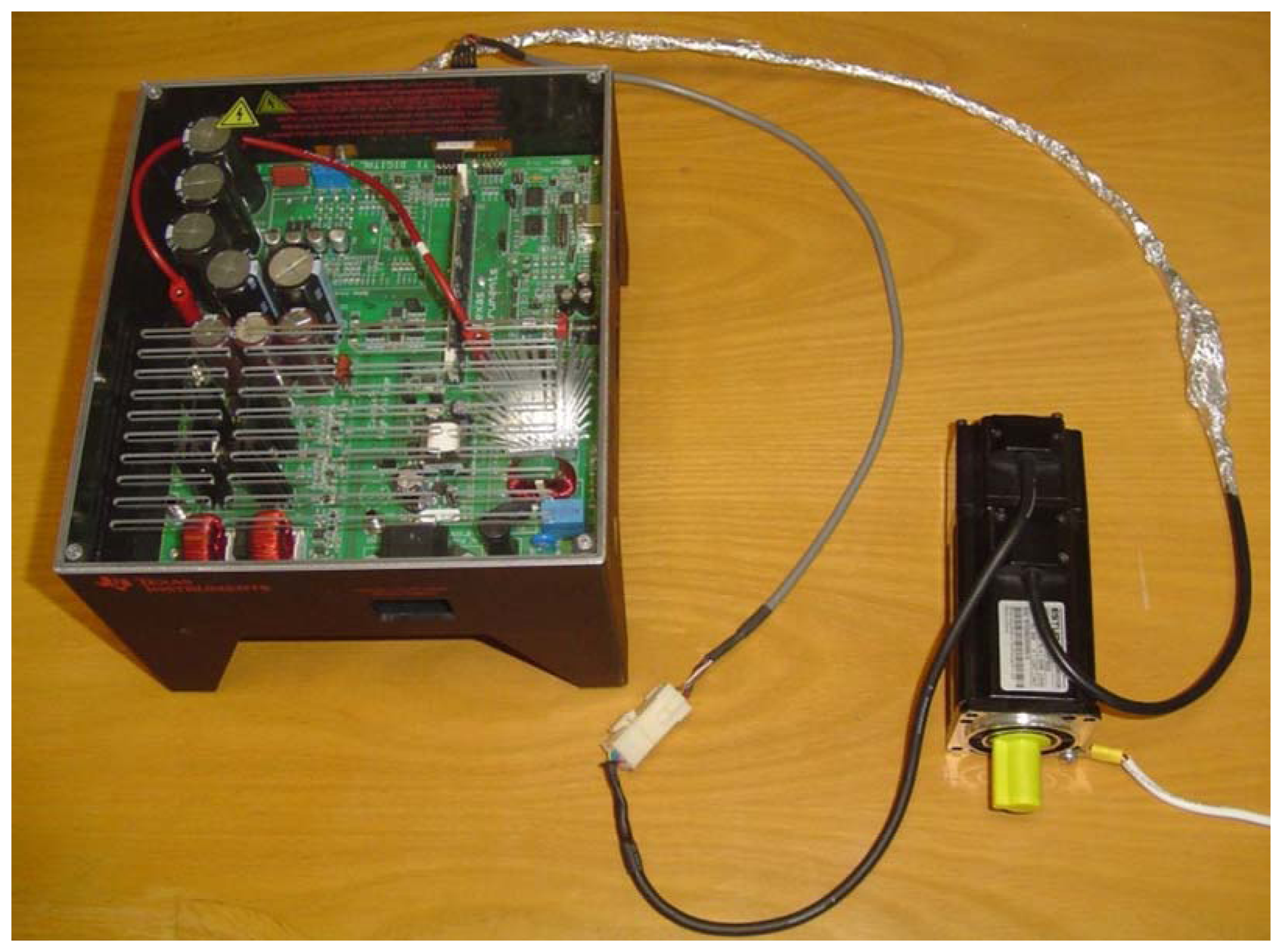
Figure 2 shows the configuration of the experiments. A TMDSHVMTRPF development system with a F28035 DSP control card is connected to the EMJ-04APB22 four pole pairs Permanent Magnet Synchronous Motor with the following parameters: 200 V, 2.7 A, 400 W maximum power, 300 rpm rated speed, 4.7 Ω, 0.014 H stator resistance and inductance, and 2500 PPR incremental encoder attached. Measurements of the variables were taken at the PWMDAC ports of the TMDSHVMTRPF development system by using a FLUKE 199C floated oscilloscope-meter, setting the bandwidth to 10 kHz for high frequency rejection. The encoder signals were coupled with a TTL Buffer (SN74LS243N Bus Transceiver), to avoid electric noise that degrades the angular position signal readings.
The performance evaluation of the controller with the proposed self-tuning algorithm is presented in the following section.
5. Experimental Results
To verify the performance of the proposed self-tuning algorithm with the Fourier series expansion scheme, experiments were performed using the setup described in the preceding section. The experiments were conducted for speeds lower than 10% of the motor's nominal speed. The performance criterion used to evaluate the performance of the proposed scheme for torque ripple minimization is the variation of the angular speed determined from the angular position measurements from the encoder.
The Standard Field Oriented Control
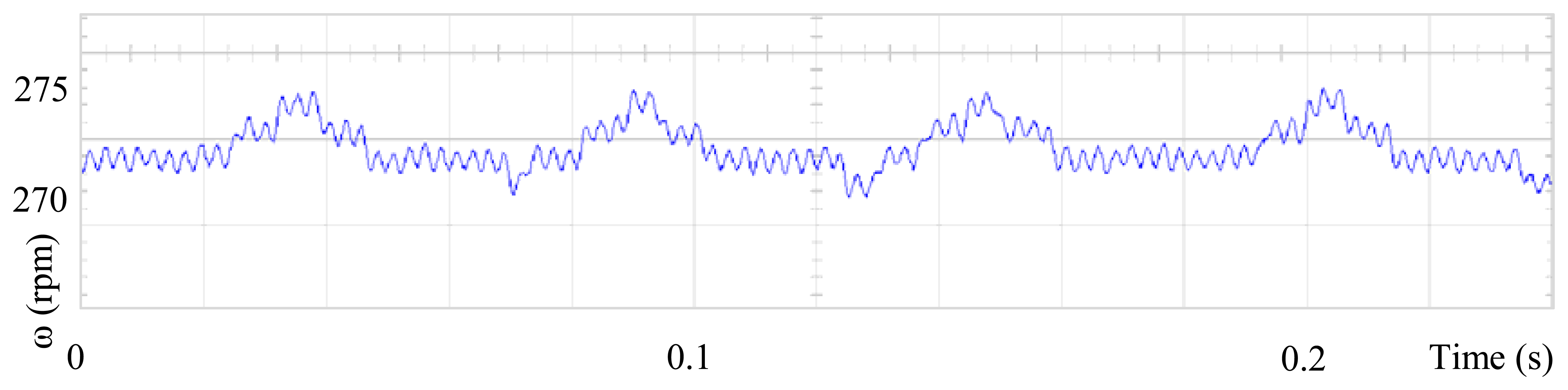
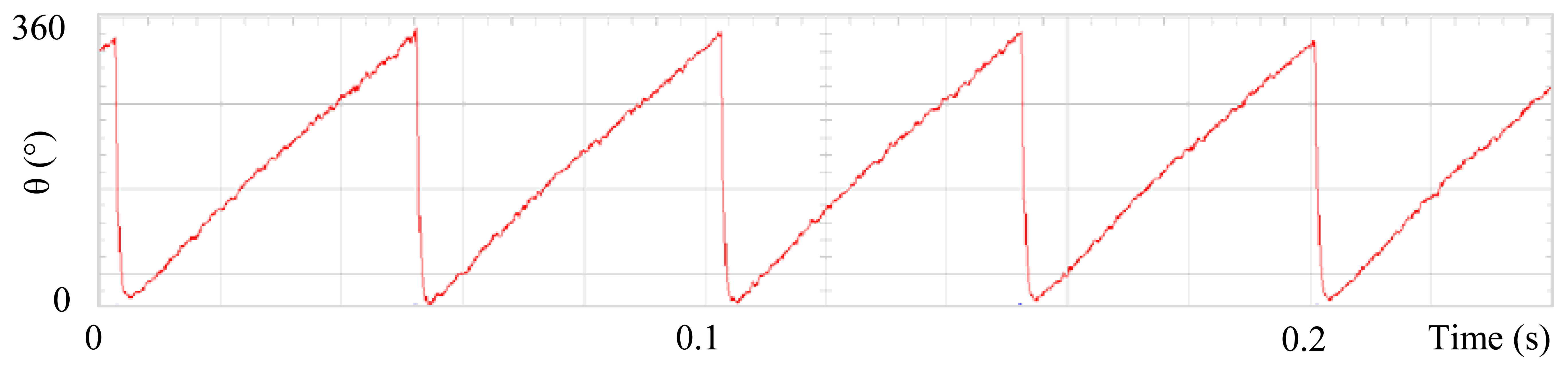
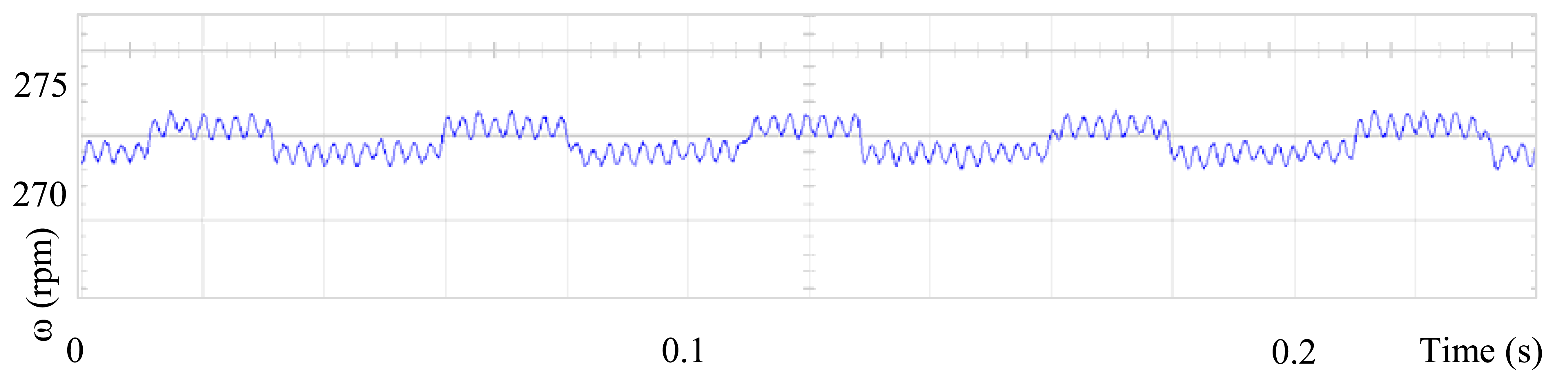
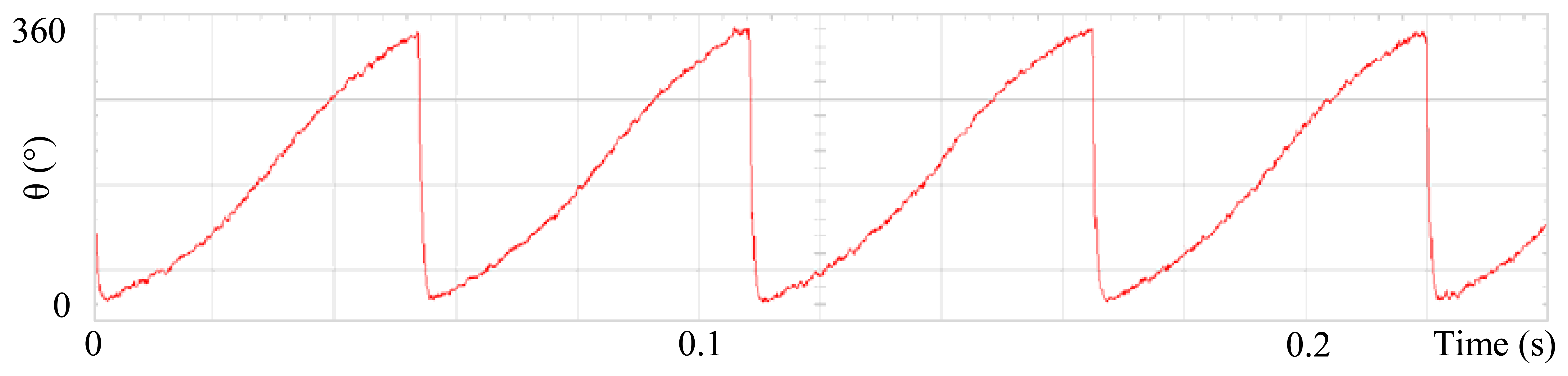
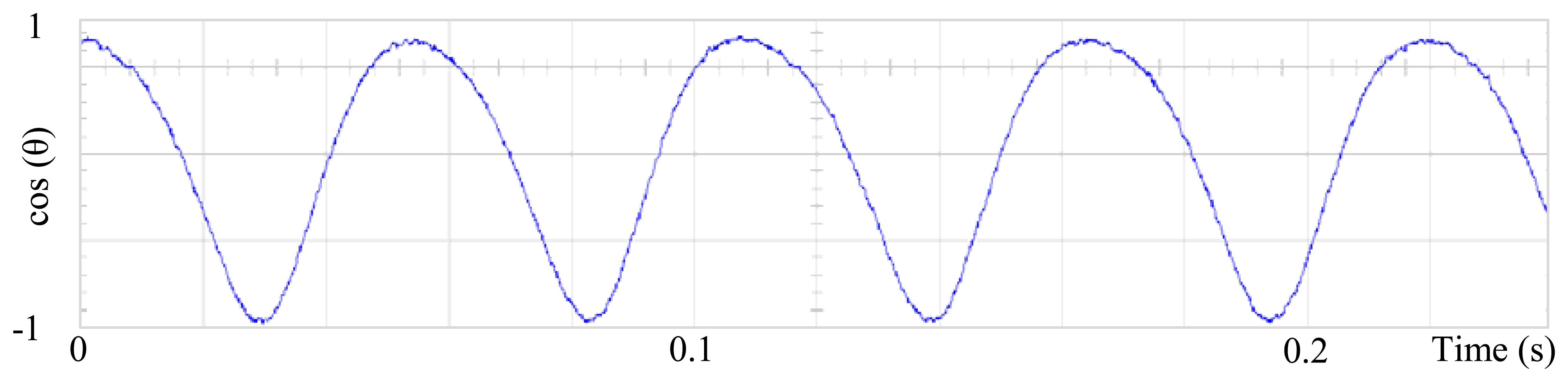
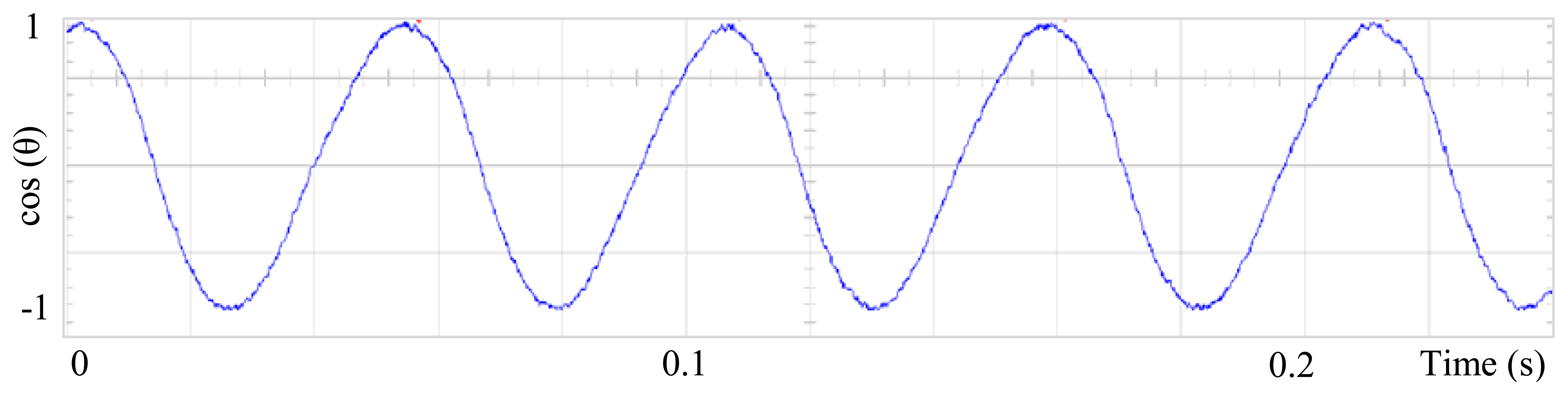
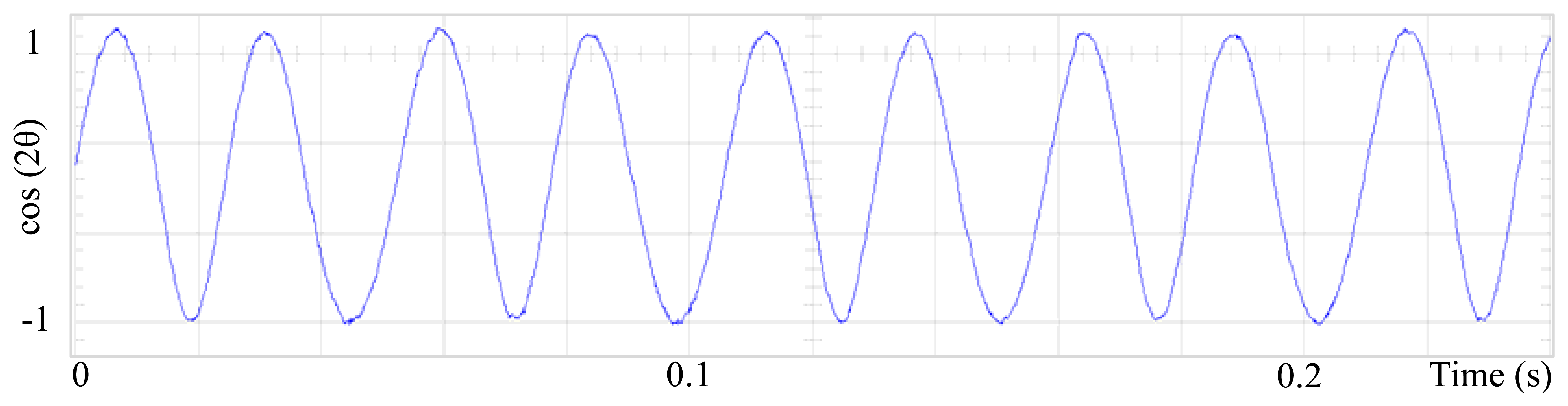
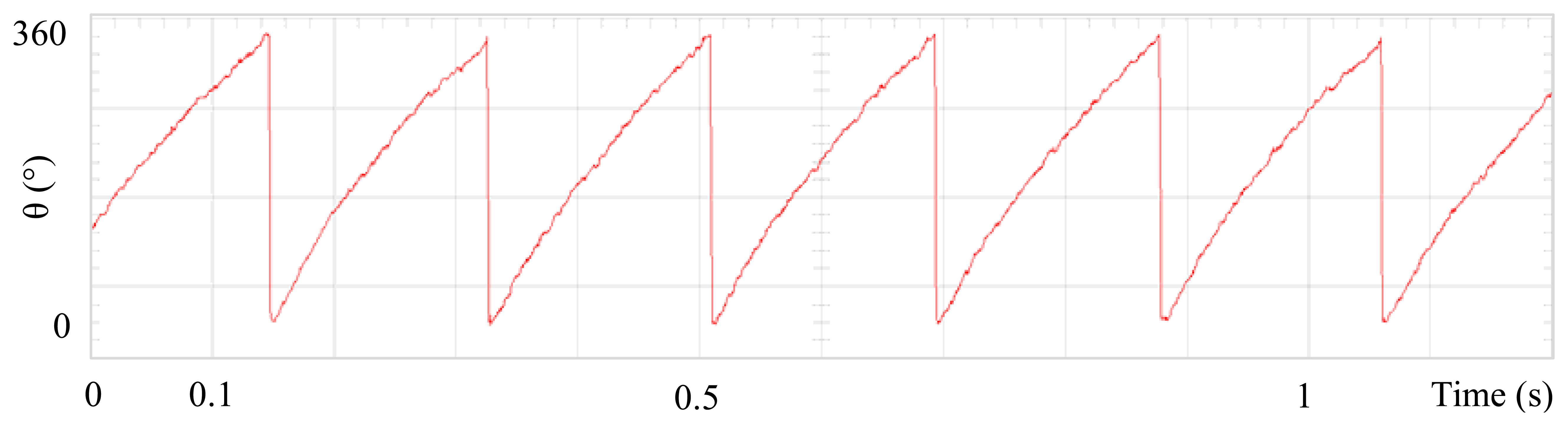
Figure 3 shows the angular position of the motor versus time, the slope of the triangular waveform change reflecting speed variations. In Figure 4 a cosine function of the angular position, with the same frequency as the perturbation fundamental frequency, is plotted against time, showing a distortion shape caused by speed variation that can be used to adjust the Fourier coefficients. Figure 5 presents the speed ripple, although it is only 1.6% of the reference speed (4.4 rpm of 273 rpm), it is responsible for distorting the previous two waveforms.
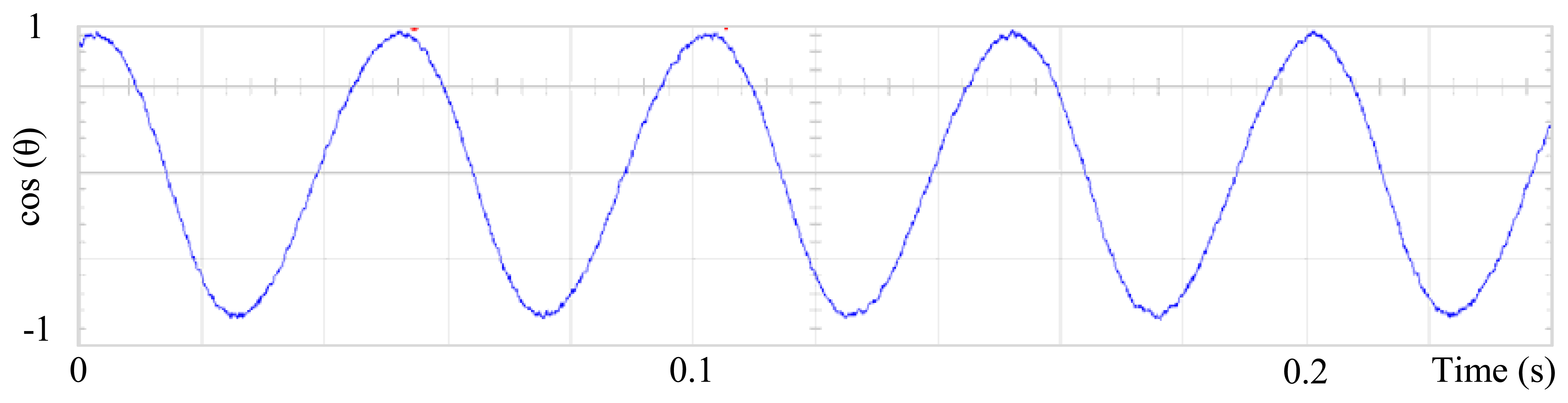
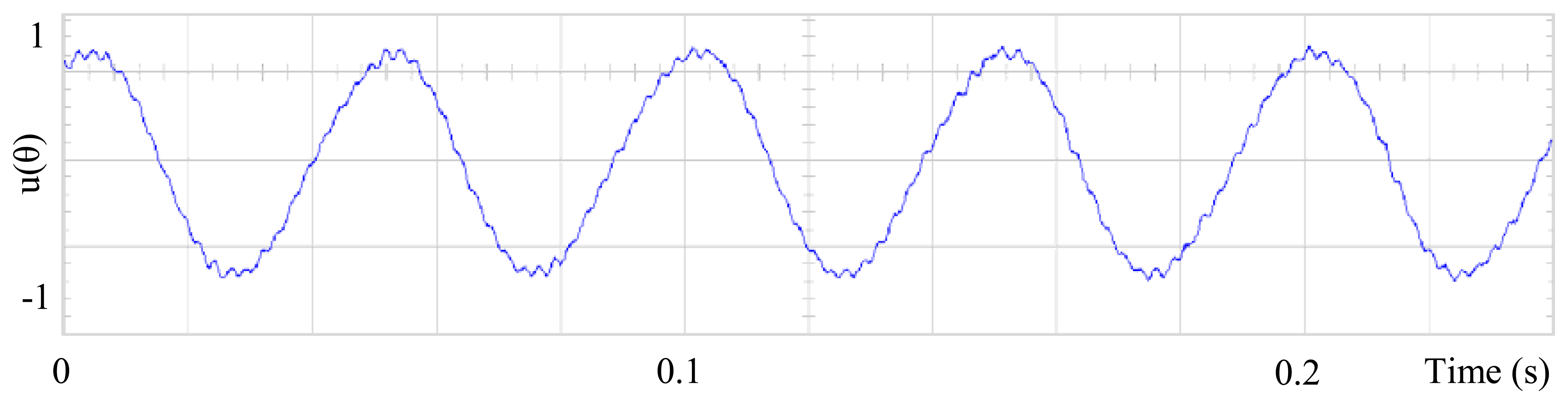
The proposed self-tuning algorithm with the Fourier series expansion scheme (for the first two terms) Figure 6 shows a reduction in angular position waveform distortion. Figure 7 verifies that the fundamental cosine function shape also improved. Figure 8 presents a 2 rpm peak to peak speed ripple which is half of the original variation as shown in Figure 5. The waveform in Figure 9 corresponds to the control signal u(θ) in per unit values.
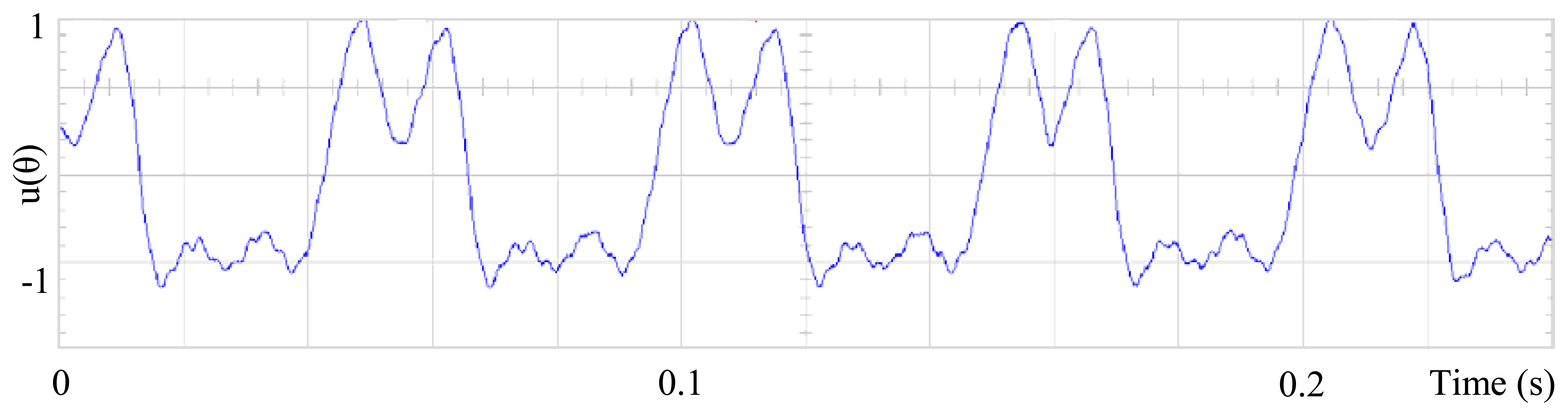
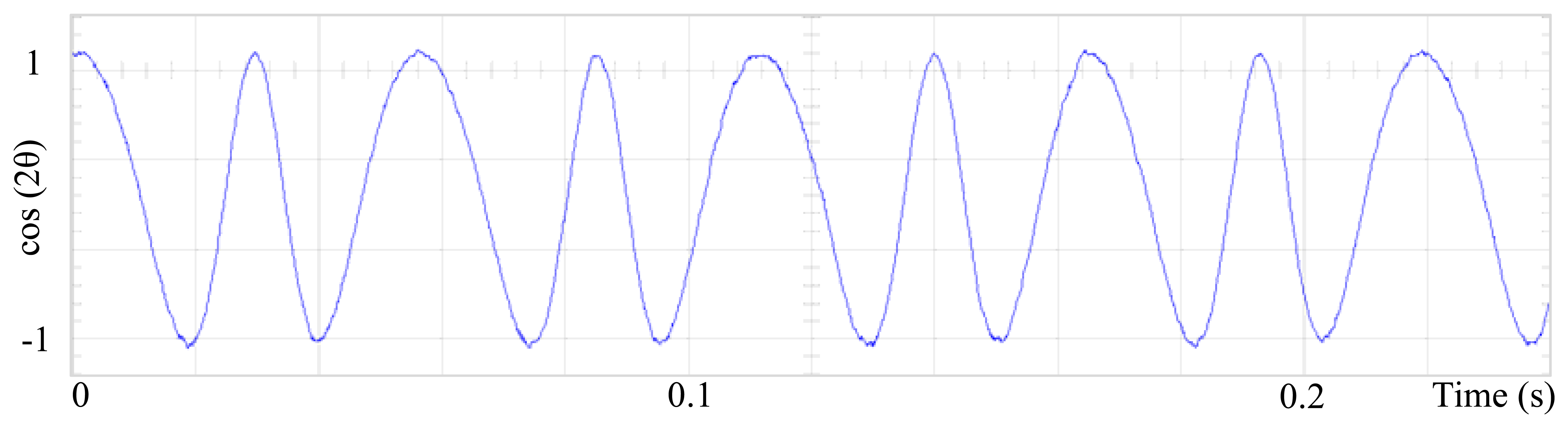
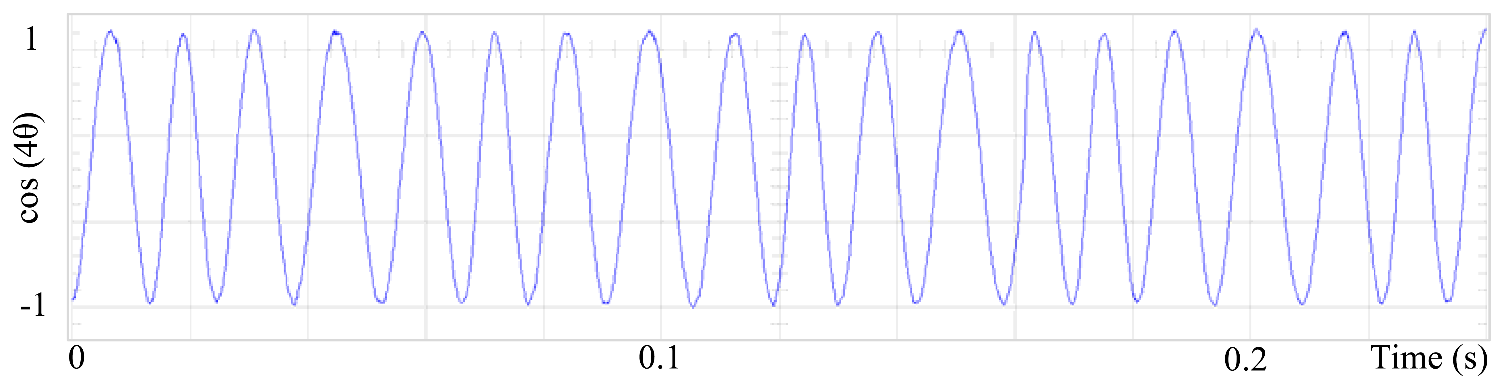
Figures 10–12 shows similar results for the proposed control for the first four terms. Figure 13 presents the control signal u(θ), although the wave forms in Figures 9 and 13 are substantially different, for this experiment the results are similar and perhaps it is because torque ripple is almost sinusoidal. Figures 14–17 shows that the second and fourth harmonic cosine function shape also improved. Finally Figure 18 shows that speed can be reduced to 2.7% of nominal speed while the motor starts to malfunction at 5.7% of nominal speed with only FOC control.
6. Conclusions
In this paper has been presented an adaptive self-tuning algorithm for determining the Fourier coefficients of the controller with the aim of reducing the torque ripple in a PMSM. Its implementation is simple and represents a good alternative for minimizing torque ripple, cogging torque and non-sinusoidal electromotive torque variations due to its periodic nature. The proposed scheme does not require previous knowledge of the motor parameters. The performance of the proposed scheme has been evaluated through experimentation and test results confirm 50% speed ripple reduction (from 4.4 rpm to 2 rpm peak to peak speed ripple). Further research should be conducted to extend these results to applications where load torque varies as periodic function, which is not considered in this work.
Acknowledgments
We gratefully acknowledge the funding for the publication of this paper provided by the Mexican Council for Science and Technology (Consejo Nacional de Ciencia y Tecnología; CONACyT), under Register No. 163660. Our thanks also extend to José Enrrique Crespo- Baltar for technical advice in the mathematical development of this paper, and to Daisie Hobson for the review of the manuscript and her valuable suggestions.
References
- Gamazo-Real, J.C.; Vázquez-Sánchez, E.; Gómez-Gil, J. Position and speed control of brushless DC motors using sensorless techniques and application trends. Sensors 2010, 10, 6901–6947. [Google Scholar]
- Dönmezer, Y.; Ergene, L.T. Cogging Torque Analysis of Interior-Type Permanent-Magnet Brushless DC Motor Used in Washers. Proceedings of the 8th International Symposium on Advanced Electromechanical Motion Systems and Electric Drives Joint Symposium, Lille, France, 1–3 July 2009; pp. 1–6.
- Nikolay, S.; Han, Q.; Jatskevich, J.J. Dynamic performance of brushless DC motors with unbalanced hall sensors. IEEE Trans. Energy Conv. 2008, 23, 752–763. [Google Scholar]
- Štumberger, B.; Štumberger, G.; Hadžiselimović, M.; Zagradišnik, I. Torque ripple reduction in exterior-rotor permanent magnet synchronous motor. J. Magn. Magn. Mater. 2006, 304, 826–828. [Google Scholar]
- Tewari, S.V.; Indu, R.B. Torque Ripple Minimization of BLDC Motor with Un-Ideal Back EMF. Proceedings of the 2nd International Conference on Emerging Trends in Engineering and Technology, Maharashtra, India, 16– 18 December 2009; pp. 687–690.
- Zhang, Y.; Zhu, J. Direct torque control of permanent magnet synchronous motor with reduced torque ripple and commutation frequency. IEEE Trans. Power Electron. 2011, 26, 235–248. [Google Scholar]
- Zhang, Y.; Zhu, J. A novel duty cycle control strategy to reduce both torque and flux ripples for DTC of permanent magnet synchronous motor drives with switching frequency reduction. IEEE Trans. Power Electron. 2011, 26, 3055–3067. [Google Scholar]
- Victor, M.H.-G.; Ramón, S.O. PI control plus electric current loops for PM synchronous motors. IEEE Trans. Contr. Syst. Technol. 2011, 19, 868–873. [Google Scholar]
- Rodríguez-Reséndiz, J.; Gutiérrez-Villalobos, J.M.; Duarte-Correa, D.; Mendiola-Santibañez, J.D.; Santillán-Méndez, I.M. Design and implementation of an adjustable speed drive for motion control applications. J. Appl. Res. Technol. 2012, 10, 180–194. [Google Scholar]
- Hoo, C.-L.; Haris, S.-M. A brief survey on artificial intelligence methods in synchronous motor control. Appl. Mechan. Mater. 2011, 52, 198–203. [Google Scholar]
- Lu, H.; Zhang, L.; Qu, W. A new torque control method for torque ripple minimization of BLDC motors with un-ideal back EMF. IEEE Trans. Power Electron. 2008, 23, 950–958. [Google Scholar]
- Cao, J.; Cao, B.; Xu, P.; Zhou, S.; Guo, G.; Wu, X. Torque Ripple Control of Position-Sensorless Brushless DC Motor Based on Neural Network Identification. Proceedings of the 3rd IEEE Conference on Industrial Electronics and Applications, Singapore, 3– 5 June 2008; pp. 752–757.
- Wang, J.; Liu, H.; Zhu, Y.; Cui, B.; Duan, H. A New Minimum Torque-Ripple and Sensorless Control Scheme of BLDC Motors Based on RBF Networks. Proceedings of the 5th International Conference on Power Electronics and Motion Control, Shanghai, China, 14– 16 August 2006; pp. 1–4.
- Kaliappan, E.; Sharmeela, C. Torque ripple minimization of permanent magnet brushless DC motor using genetic algorithm. Power Electron. Instrum. Eng. 2010, 2, 53–55. [Google Scholar]
- Liu, Y.; Zhu, Z.Q.; Howe, D. Direct torque control of brushless DC drives with reduced torque ripple. IEEE Trans. Ind. Appl. 2005, 41, 599–608. [Google Scholar]
- Muruganantham, N.; Palani, S. State space modeling and simulation of sensorless permanent magnet BLDC motor. Int. J. Eng. Sci. Technol. 2010, 2, 5099–5106. [Google Scholar]
- Varatharaju, V.M.; Mathur, B.L.; Udhayakumar, K. A comparative study with modeling and simulation of torque ripple reduction techniques in BLDC motor. Eur. J. Sci. Res. 2011, 52, 295–305. [Google Scholar]
- Kim, I.; Nakazawa, N.; Kim, S.; Park, C.; Yu, C. Compensation of torque ripple in high performance BLDC motor drives. Contr. Eng. Pract. 2008, 18, 1166–1172. [Google Scholar]
- Mattavelli, P.; Tubiana, L.; Zigliotto, M. Torque-ripple reduction in PM synchronous motor drives using repetitive current control. IEEE Trans. Power Electron. 2005, 20, 1423–1431. [Google Scholar]
- Kasac, J.; Novakovic, B.; Majetic, D.; Brezak, D. Passive finite-dimensional repetitive control of robot manipulators. IEEE Trans. Contr. Syst. Technol. 2008, 16, 570–576. [Google Scholar]
- Aghili, F. Adaptive reshaping of excitation currents for accurate torque control of brushless motors. IEEE Trans. Contr. Syst. Technol. 2008, 16, 356–364. [Google Scholar]
- Vladan, P.; Romeo, O.; Aleksandamr, M.S.; Gilead, T. Design and implementation of an adaptive controller for torque ripple minimization in PM synchronous motors. IEEE Trans. Power Electron. 2000, 15, 871–880. [Google Scholar]
- Varatharaju, V.M.; Mathur, B.L.; Udhayakumar, K. Recursive least square algorithm based selective current harmonic elimination in PMBLDC motor drive. Int. J. Comput. Appl. 2011, 30, 32–38. [Google Scholar]
- Qian, W.; Panda, S.K.; Xu, J. Torque ripple minimization in PM synchronous motors using iterative learning control. IEEE Trans. Power Electron. 2004, 19, 272–279. [Google Scholar]
- Panda, S.K.; Xu, J.; Qian, W. Review of Torque Ripple Minimization in PM Synchronous Motor Drives. Proceedings of the IEEE Power and Energy Society General Meeting-Conversion and Delivery of Electrical Energy in the 21st Century, Pittsburgh, PA, USA, 20– 24 July 2008; pp. 1–6.
- Xu, J.; Cao, W. Improved Tracking Performance of Variable Structure Control Using Fourier Series Based Iterative Learning. Proceedings of the 38th IEEE Conference on Decision and Control, Phoenix, AZ, USA, 7– 10 December 1999; pp. 5140–5145.
- Xu, J.; Lee, T.H.; Zhang, H.W. Analysis and Comparison of Two Practical Iterative Learning Control Schemes. Proceedings of the IEEE International Conference on Control Applications, Taipei, Taiwan, 2– 4 September 2004; pp. 382–387.
- Xu, J.; Wang, X.; Lee, T.H. Analysis of Continuous Iterative Learning Control Systems Using Current Cycle Feedback. Proceedings of the IEEE American Control Conference, Seattle, WA, USA, 21– 23 June 1995; pp. 4221–4225.
- Xu, J.; Lee, T.H.; Nair, N. A Revised Iterative Learning Control Strategy for Robotic Manipulators. Proceedings of the Asia-Pacific Workshop on Advances in Motion Control, Singapore, 15– 16 July 1993; pp. 88–93.
- Marino, R.; Tomei, P.; Verrelli, C.M. Position Learning Control for Current-Fed Permanent Magnet Step Motors with Uncertainties. Proceeding of the 10th IEEE International Workshop on Advanced Motion Control, Trento, Italy, 26– 28 March 2008; pp. 699–703.
- Bifaretti, S.; Tomei, P.; Verrelli, C.M. A Global Robust Iterative Learning Position Control for Current-Fed Permanent Magnet Step Motors. Proceeding of the IEEE International Symposium on Industrial Electronics, Bari, Italy, 4– 7 July 2010; pp. 30–35.
- Bifaretti, S.; Iacovone, V.; Rocchi, A.; Tomei, P.; Verrelli, C.M. Global learning position controls for permanent-magnet step motors. IEEE Trans. Ind. Electron. 2011, 58, 4654–4663. [Google Scholar]
- Lyshevski, S.E. Electromechanical Systems, Electric Machines, and Applied Mechatronics; CRC Press: Boca Raton, FL, USA, 2000. [Google Scholar]
- Krishnan, R. Dynamic Modeling of Permanent Magnet Synchronous Machines. In Permanente Magnet Synchronous and Brushless DC Motor Drives; CRC Press: Boca Raton, FL, USA, 2010; pp. 225–276. [Google Scholar]
- Hanselmanl, D.C. Brushless Motor Fundamentals. In Brushless Permanent Magnet Motor Design; Magna Physics Pub.: Hillsboro, OH, USA, 2006; pp. 67–116. [Google Scholar]


© 2013 by the authors; licensee MDPI, Basel, Switzerland. This article is an open access article distributed under the terms and conditions of the Creative Commons Attribution license (http://creativecommons.org/licenses/by/3.0/).
Share and Cite
Gómez-Espinosa, A.; Hernández-Guzmán, V.M.; Bandala-Sánchez, M.; Jiménez-Hernández, H.; Rivas-Araiza, E.A.; Rodríguez-Reséndiz, J.; Herrera-Ruíz, G. A New Adaptive Self-Tuning Fourier Coefficients Algorithm for Periodic Torque Ripple Minimization in Permanent Magnet Synchronous Motors (PMSM). Sensors 2013, 13, 3831-3847. https://doi.org/10.3390/s130303831
Gómez-Espinosa A, Hernández-Guzmán VM, Bandala-Sánchez M, Jiménez-Hernández H, Rivas-Araiza EA, Rodríguez-Reséndiz J, Herrera-Ruíz G. A New Adaptive Self-Tuning Fourier Coefficients Algorithm for Periodic Torque Ripple Minimization in Permanent Magnet Synchronous Motors (PMSM). Sensors. 2013; 13(3):3831-3847. https://doi.org/10.3390/s130303831
Chicago/Turabian StyleGómez-Espinosa, Alfonso, Víctor M. Hernández-Guzmán, Manuel Bandala-Sánchez, Hugo Jiménez-Hernández, Edgar A. Rivas-Araiza, Juvenal Rodríguez-Reséndiz, and Gilberto Herrera-Ruíz. 2013. "A New Adaptive Self-Tuning Fourier Coefficients Algorithm for Periodic Torque Ripple Minimization in Permanent Magnet Synchronous Motors (PMSM)" Sensors 13, no. 3: 3831-3847. https://doi.org/10.3390/s130303831