<?xml version="1.0" encoding="UTF-8"?>
<!DOCTYPE article PUBLIC "-//NLM//DTD Journal Publishing DTD v2.3 20070202//EN" "journalpublishing.dtd">
<article xmlns:mml="http://www.w3.org/1998/Math/MathML" xmlns:xlink="http://www.w3.org/1999/xlink" xml:lang="en" article-type="research-article">
<front>
<journal-meta>
<journal-id journal-id-type="nlm-ta">Sensors</journal-id>
<journal-title>Sensors</journal-title>
<issn pub-type="epub">1424-8220</issn>
<publisher>
<publisher-name>Molecular Diversity Preservation International (MDPI)</publisher-name></publisher></journal-meta>
<article-meta>
<article-id pub-id-type="doi">10.3390/s121216628</article-id>
<article-id pub-id-type="publisher-id">sensors-12-16628</article-id>
<article-categories>
<subj-group>
<subject>Article</subject></subj-group></article-categories>
<title-group>
<article-title>Design and Test of a Soft Plantar Force Measurement System for Gait Detection</article-title></title-group>
<contrib-group>
<contrib contrib-type="author">
<name><surname>Zhang</surname><given-names>Xuefeng</given-names></name></contrib>
<contrib contrib-type="author">
<name><surname>Zhao</surname><given-names>Yulong</given-names></name><xref ref-type="corresp" rid="c1-sensors-12-16628"><sup>*</sup></xref></contrib>
<contrib contrib-type="author">
<name><surname>Duan</surname><given-names>Zhengyong</given-names></name></contrib>
<contrib contrib-type="author">
<name><surname>Liu</surname><given-names>Yan</given-names></name></contrib>
<aff id="af1-sensors-12-16628">State Key Laboratory for Manufacturing Systems Engineering, Xi’an Jiaotong University, No. 28, Xianning West Road, Xi’an, Shaanxi 710049, China; E-Mails: <email>bssair@163.com</email> (X.Z.); <email>dzyai@163.com</email> (Z.D.); <email>ZTlover@stu.xjtu.edu.cn</email> (Y.L.)</aff></contrib-group>
<author-notes>
<corresp id="c1-sensors-12-16628">
<label>*</label>Author to whom correspondence should be addressed; E-Mail: <email>zhaoyulong@mail.xjtu.edu.cn</email>; Tel./Fax: +86-29-8339-5073.</corresp></author-notes>
<pub-date pub-type="collection">
<month>12</month>
<year>2012</year></pub-date>
<pub-date pub-type="epub">
<day>03</day>
<month>12</month>
<year>2012</year></pub-date>
<volume>12</volume>
<issue>12</issue>
<fpage>16628</fpage>
<lpage>16640</lpage>
<history>
<date date-type="received">
<day>29</day>
<month>09</month>
<year>2012</year></date>
<date date-type="rev-recd">
<day>23</day>
<month>11</month>
<year>2012</year></date>
<date date-type="accepted">
<day>26</day>
<month>11</month>
<year>2012</year></date></history>
<permissions>
<copyright-statement>© 2012 by the authors; licensee MDPI, Basel, Switzerland</copyright-statement>
<copyright-year>2012</copyright-year>
<license>
<p>This article is an open access article distributed under the terms and conditions of the Creative Commons Attribution license (http://creativecommons.org/licenses/by/3.0/).</p></license></permissions>
<abstract>
<p>This work describes a plantar force measurement system. The MEMS pressure sensor, as the key sensing element, is designed, fabricated and embedded into a flexible silicon oil-filled bladder made of silicon rubber to constitute a single sensing unit. A conditioning circuit is designed for signal processing and data acquisition. The characteristics of the plantar force sensing unit are investigated by both static and dynamic tests. A comparison of characteristics between the proposed plantar force sensing unit and a commercial flexible force sensor is presented. A practical experiment of plantar force measurement has been carried out to validate the system. The results demonstrate that the proposed measurement system has a potential for success in the application of plantar force measurement during normal gait.</p></abstract>
<kwd-group>
<kwd>MEMS</kwd>
<kwd>plantar force</kwd>
<kwd>gait detection</kwd>
<kwd>flexible</kwd></kwd-group></article-meta></front>
<body>
<sec sec-type="intro">
<label>1.</label>
<title>Introduction</title>
<p>The plantar force is frequently measured as an important biomechanical parameter that can reflect the supporting situation and stability of the human gait. Potential applications of a plantar force measurement system include rehabilitation science [<xref ref-type="bibr" rid="b1-sensors-12-16628">1</xref>–<xref ref-type="bibr" rid="b4-sensors-12-16628">4</xref>], athletic sports [<xref ref-type="bibr" rid="b5-sensors-12-16628">5</xref>,<xref ref-type="bibr" rid="b6-sensors-12-16628">6</xref>], robotics technology [<xref ref-type="bibr" rid="b7-sensors-12-16628">7</xref>], <italic>etc.</italic> Development of a simple, easily used, high-performance prototype for plantar force measurement has attracted extraordinary research interest.</p>
<p>Most current plantar force sensors are based on conductive polymers [<xref ref-type="bibr" rid="b8-sensors-12-16628">8</xref>–<xref ref-type="bibr" rid="b12-sensors-12-16628">12</xref>]. However, research shows that their performance with regards to repeatability, hysteresis, creep and linearity fail to meet the requirements of accurate plantar force measurement [<xref ref-type="bibr" rid="b12-sensors-12-16628">12</xref>–<xref ref-type="bibr" rid="b14-sensors-12-16628">14</xref>]. Various improved designs have been proposed to solve the above-mentioned problems. Tomizuka developed a smart shoe to monitor the human gait by embedding a commercial air pressure sensor in a shoe [<xref ref-type="bibr" rid="b3-sensors-12-16628">3</xref>]. However, the complication of its compensation algorithm might restrict its popularity. Chedevergne <italic>et al.</italic> presented a plant force sensor formed by a metallic ring equipped with a strain gauge [<xref ref-type="bibr" rid="b15-sensors-12-16628">15</xref>], but the proposed metallic element would introduce discomfort and alter the natural gait. New devices have sprung up with the development of new materials and technology. De Rossi <italic>et al.</italic> introduced a pressure sensitive device consisting of silicone covered opto-electronic pressure sensors and a high-frequency data processing system [<xref ref-type="bibr" rid="b16-sensors-12-16628">16</xref>]. Shu <italic>et al.</italic> provided a design of a plantar pressure measurement system based on a fabric pressure sensing array [<xref ref-type="bibr" rid="b17-sensors-12-16628">17</xref>]. Both of them offer new approaches for plantar pressure measurement. Karki <italic>et al.</italic> reported a piezoelectric polymer film sensor for plantar normal and shear stress measurements [<xref ref-type="bibr" rid="b18-sensors-12-16628">18</xref>]. The signal conditioning of piezoelectric sensors is complicated, and the influence of a charge amplifier on the dynamic characteristics of a piezoelectric sensor should be analyzed carefully. Meantime, several flexible capacitive sensors have been proposed and tested [<xref ref-type="bibr" rid="b19-sensors-12-16628">19</xref>–<xref ref-type="bibr" rid="b21-sensors-12-16628">21</xref>], but the accuracy of the capacitive sensor is greatly affected by the external environment. Meanwhile, piezoresistivity has been widely used in the design of MEMS pressure sensors because of its simple signal processing, high sensitivity, and excellent linearity. Piezoresistive MEMS pressure sensors have been used in biomechanical applications by employing special packing structures and designs [<xref ref-type="bibr" rid="b12-sensors-12-16628">12</xref>,<xref ref-type="bibr" rid="b22-sensors-12-16628">22</xref>]. However, difficult processes were required to package pressure sensors in a sole. Meanwhile, the failure of pressure sensors when overloaded must be taken into account.</p>
<p>Considering the features mentioned above, a soft plantar force measurement system with a MEMS pressure sensor is proposed in this paper. By encapsulating a piezoresistive pressure sensor into a silicon oil-filled bladder made from silicon rubber, a sensing unit with good performance is expected. In addition, overload protection is anticipated due to the existence of silicon oil to transmit the pressure and limit the compression of the bladder. As piezoresistivity is utilized to realize the sensing unit, low cost and a simple signal process can be expected. To accurately measure the plantar force, three plantar force sensing units are placed in the sole, and the processing electrics and data acquisition circuit are combined to realize the plantar force measurement system. The proposed prototype has been applied in the practical plantar force measurement, and comparisons have been done to evaluate the effectiveness of the proposed measurement system.</p></sec>
<sec sec-type="methods">
<label>2.</label>
<title>Design of the Pressure Sensor</title>
<p>
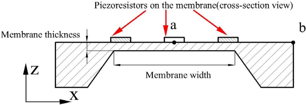
A MEMS pressure sensor is used as the key component in detecting the variation of the plantar force during walking. The sensor consists of a square diaphragm with four p-type piezoresistors located on the edges of diaphragm. A full Wheatstone bridge is integrated in the sensor chip to utilize the longitudinal and transversal piezoresistive effect of silicon. The conceptual design model of the pressure sensor is shown in <xref ref-type="fig" rid="f1-sensors-12-16628">Figure 1</xref>.</p>
<p>A square membrane is used as the sensitive structure for its higher induced stress when compared with a circular membrane. Theoretical model of the square membrane is established to specify the relationship of length, thickness and effective stress. According to the mechanics principle of the periphery fixed square diaphragm, the maximum deflection at the central point a can be expressed as:
<disp-formula id="FD1">
<label>(1)</label>
<mml:math id="mm1" display="block">
<mml:mrow>
<mml:msub>
<mml:mrow>
<mml:mi>w</mml:mi></mml:mrow>
<mml:mrow>
<mml:mtext>max</mml:mtext></mml:mrow></mml:msub>
<mml:mo>=</mml:mo>
<mml:mn>0.0151</mml:mn>
<mml:mfrac>
<mml:mrow>
<mml:mi>p</mml:mi>
<mml:msup>
<mml:mrow>
<mml:mi>a</mml:mi></mml:mrow>
<mml:mn>4</mml:mn></mml:msup></mml:mrow>
<mml:mrow>
<mml:mi>E</mml:mi>
<mml:msup>
<mml:mrow>
<mml:mi>h</mml:mi></mml:mrow>
<mml:mn>3</mml:mn></mml:msup></mml:mrow></mml:mfrac>
<mml:mo stretchy="false">(</mml:mo>
<mml:mn>1</mml:mn>
<mml:mo>−</mml:mo>
<mml:msup>
<mml:mrow>
<mml:mi>v</mml:mi></mml:mrow>
<mml:mn>2</mml:mn></mml:msup>
<mml:mo stretchy="false">)</mml:mo></mml:mrow></mml:math></disp-formula>where <italic>a</italic> and <italic>h</italic> denote the length and thickness of the diaphragm and <italic>p</italic> is the applied pressure. <italic>E</italic> and <italic>v</italic> are the Young’s modulus and the Poisson ratio of silicon, respectively. The maximum stress occurs at the middle of four edges and is given by:
<disp-formula id="FD2">
<label>(2)</label>
<mml:math id="mm2" display="block">
<mml:mrow>
<mml:msub>
<mml:mrow>
<mml:mo>|</mml:mo>
<mml:mi>σ</mml:mi>
<mml:mo>|</mml:mo></mml:mrow>
<mml:mrow>
<mml:mtext>max</mml:mtext></mml:mrow></mml:msub>
<mml:mo>=</mml:mo>
<mml:mn>0.308</mml:mn>
<mml:mfrac>
<mml:mrow>
<mml:mi>p</mml:mi>
<mml:msup>
<mml:mrow>
<mml:mi>a</mml:mi></mml:mrow>
<mml:mn>2</mml:mn></mml:msup></mml:mrow>
<mml:mrow>
<mml:msup>
<mml:mrow>
<mml:mi>h</mml:mi></mml:mrow>
<mml:mn>2</mml:mn></mml:msup></mml:mrow></mml:mfrac></mml:mrow></mml:math></disp-formula></p>
<p>The corresponding strain is:
<disp-formula id="FD3">
<label>(3)</label>
<mml:math id="mm3" display="block">
<mml:mrow>
<mml:mi>ε</mml:mi>
<mml:mo>=</mml:mo>
<mml:mfrac>
<mml:mrow>
<mml:mn>1</mml:mn>
<mml:mo>−</mml:mo>
<mml:mi>v</mml:mi></mml:mrow>
<mml:mi>E</mml:mi></mml:mfrac>
<mml:mi>σ</mml:mi></mml:mrow></mml:math></disp-formula></p>
<p>
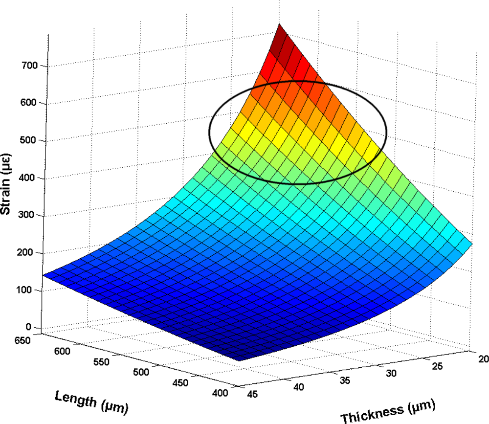
Numerical analysis by Matlab is performed to identify the effective range of parameters. The pressure applied on the sole is up to 400 kPa during walking [<xref ref-type="bibr" rid="b21-sensors-12-16628">21</xref>], therefore the load is set as 400 kPa, and the obtained results are shown in <xref ref-type="fig" rid="f2-sensors-12-16628">Figure 2</xref>. Based on the numerical analysis, a set of data of diaphragm thickness and length (marked by the circle) are chosen for further optimization.</p>
<p>
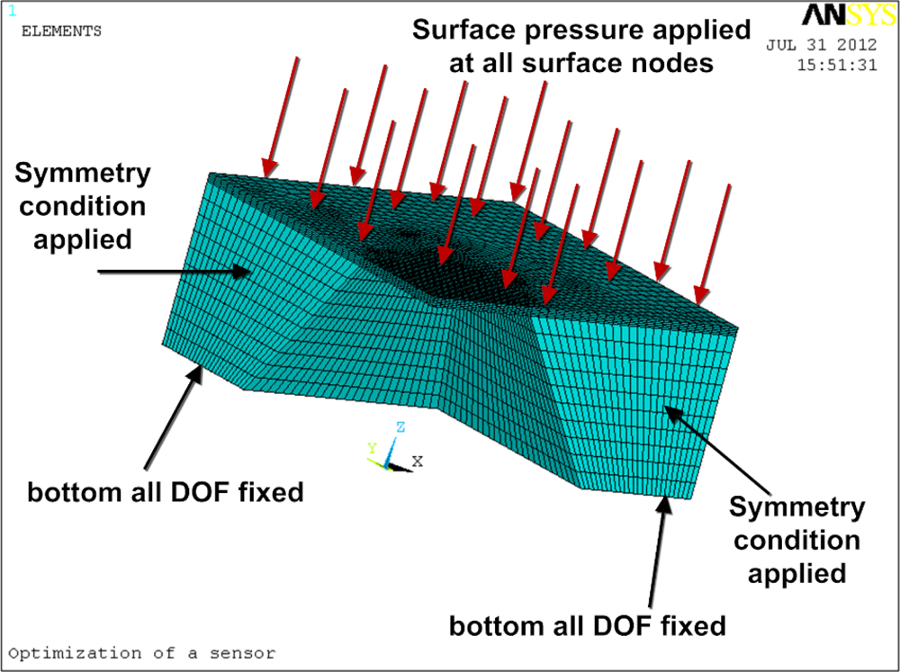
FEM optimal design based on ANSYS is performed to finally specify the feasible parameters. The determined structural parameters can guarantee that the pressure sensor have the highest attainable sensitivity and stability at the same time. One fourth of the chip is modeled and simulated considering its complete symmetry. <xref ref-type="fig" rid="f3-sensors-12-16628">Figure 3</xref> shows the finite element model with the constrain conditions and applied pressure.</p>
<p>
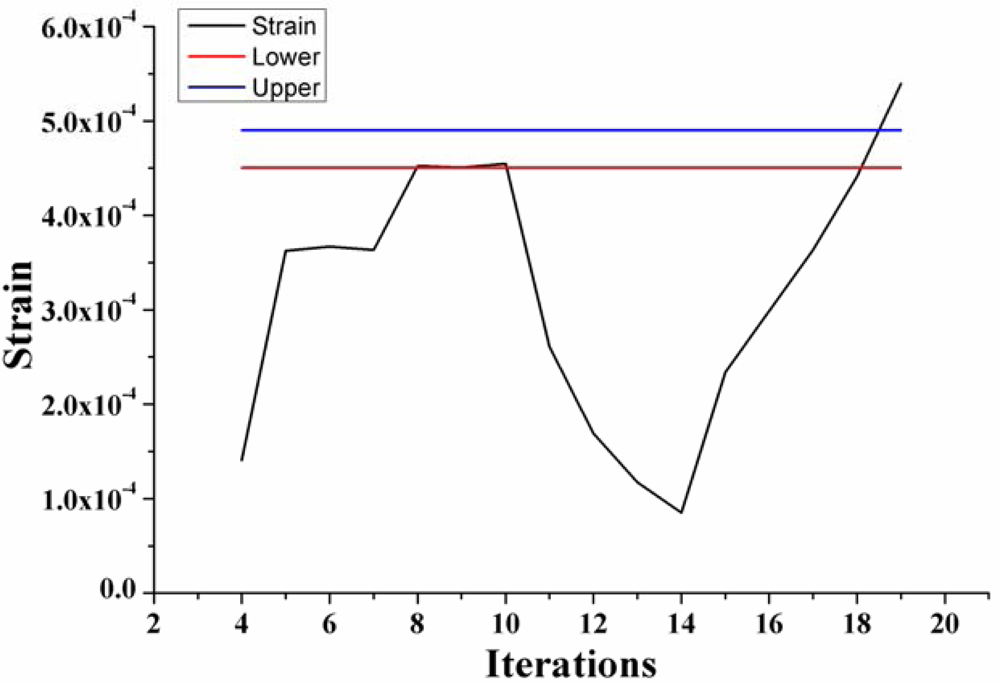
In the optimal design, the thickness and length of diaphragm are the design variables, strain is the state variable and minimum volume is the objective [<xref ref-type="bibr" rid="b23-sensors-12-16628">23</xref>]. According to the numerical analysis results and process capacity, the thickness is considered in a range of 20–45 μm and length is in a range of 400–600 μm, respectively. The strain is confined in the range of (450–490) × 10<sup>−6</sup> to assure a sensor output with high linearization [<xref ref-type="bibr" rid="b24-sensors-12-16628">24</xref>]. <xref ref-type="fig" rid="f4-sensors-12-16628">Figure 4</xref> shows the state variable change curve with the iterations.</p>
<p>
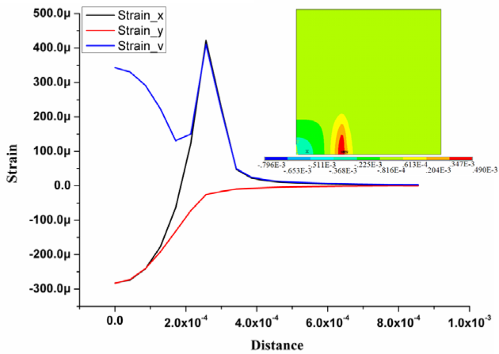
From the optimal result, the combination of diaphragm length 553 μm and thickness 20 μm is an optimal solution for the sensor design, which can balance the reliability and the sensitivity. The FEM simulation results of the pressure sensor chip with defined dimensions are shown in <xref ref-type="fig" rid="f5-sensors-12-16628">Figure 5</xref>, which shows the strain distribution on the top surface of the sensor chip and the strain distribution curve along the defined path. The path starts from the sensor chip center (point a) to the edge (point b) along the x-axis, as demonstrated in <xref ref-type="fig" rid="f1-sensors-12-16628">Figure 1</xref>. Strain_v, strain_x and strain_y represent the von-Mises, transverse, and longitudinal strain results, respectively. The maximum strain difference is located at the edge of the membrane where the resistors are implanted.</p></sec>
<sec>
<label>3.</label>
<title>Realization of the Measurement System Prototype</title>
<sec>
<label>3.1.</label>
<title>Fabrication of the Pressure Sensor</title>
<p>
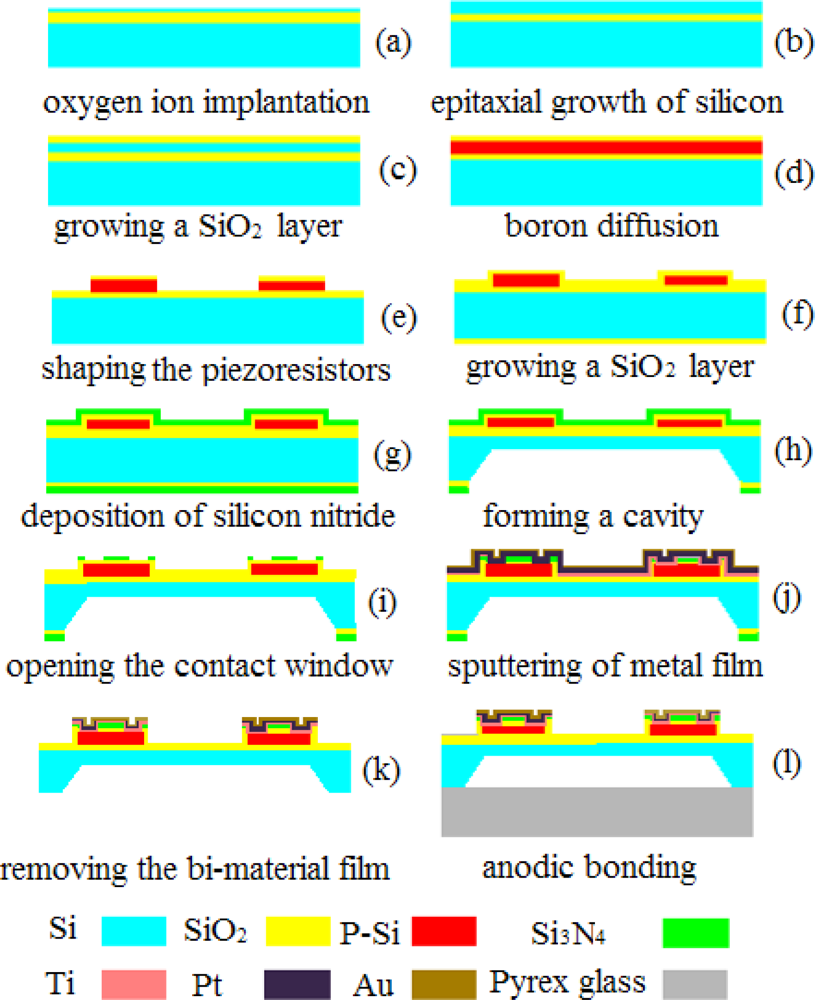
The pressure sensors were fabricated by silicon micromachining. Silicon on insulator (SOI) technology is used to fabricate the designed pressure sensor, to reduce parasitic device capacitance, thereby improving performance [<xref ref-type="bibr" rid="b25-sensors-12-16628">25</xref>]. A 400 μm, double side polished, n-type, (100) oriented silicon wafer was used as the starting material. The fabrication process steps are illustrated in <xref ref-type="fig" rid="f6-sensors-12-16628">Figure 6</xref>.</p>
<p>
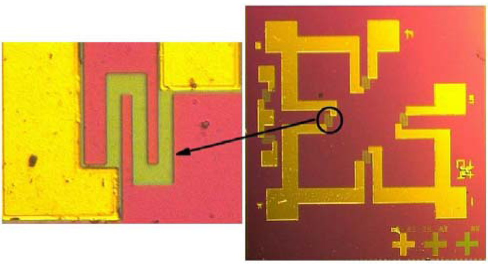
A total of four masks were necessary, for the fabrication of piezoresistors, the etching of back cavity, the fairlead and the metal wire. The fabrication sequences started with creating a buried SiO<sub>2</sub> layer by oxygen ion implantation (a), epitaxial growth of silicon using LPCVD (b), growing a SiO<sub>2</sub> layer using thermal oxidation (c), followed by boron diffusion for resistors (d), preliminary shaping the piezoresistors by plasma etching (e), growing a SiO<sub>2</sub> layer by thermal oxidation (f), depositing a silicon nitride layer (g), forming a cavity on the backside by wet etching technique (h), creating the bond pads and conductors (i,j,k), and ended with attachment of Pyrex glass to the silicon substrate by anodic bonding (l). With respect to the boron diffusion, light impurity concentration was controlled at about 5 × 10<sup>18</sup> cm<sup>−3</sup> and thus the nominal sheet resistance approximated to 200 Ω. By applying such processes, a micro pressure sensor chip was fabricated as shown in <xref ref-type="fig" rid="f7-sensors-12-16628">Figure 7</xref>, with one of the piezoresistors in an enlarged view.</p>
<p>
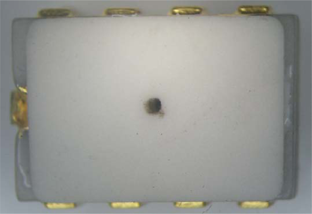
To prepare for subsequent applications, a ceramic dual-in-line package was designed to provide the sensor chip with mechanical support, power and signal paths, environmental protection, and/or interface protection [<xref ref-type="bibr" rid="b26-sensors-12-16628">26</xref>]. A strong epoxy adhesive was used to mount the chip into the package, and the pads were bonded to the pins correspondingly. A lid with an air inlet was glued on the package to finish the package [<xref ref-type="bibr" rid="b27-sensors-12-16628">27</xref>,<xref ref-type="bibr" rid="b28-sensors-12-16628">28</xref>]. A packaged pressure sensor is shown in <xref ref-type="fig" rid="f8-sensors-12-16628">Figure 8</xref>.</p></sec>
<sec>
<label>3.2.</label>
<title>Assembling of the Sensing Unit</title>
<p>
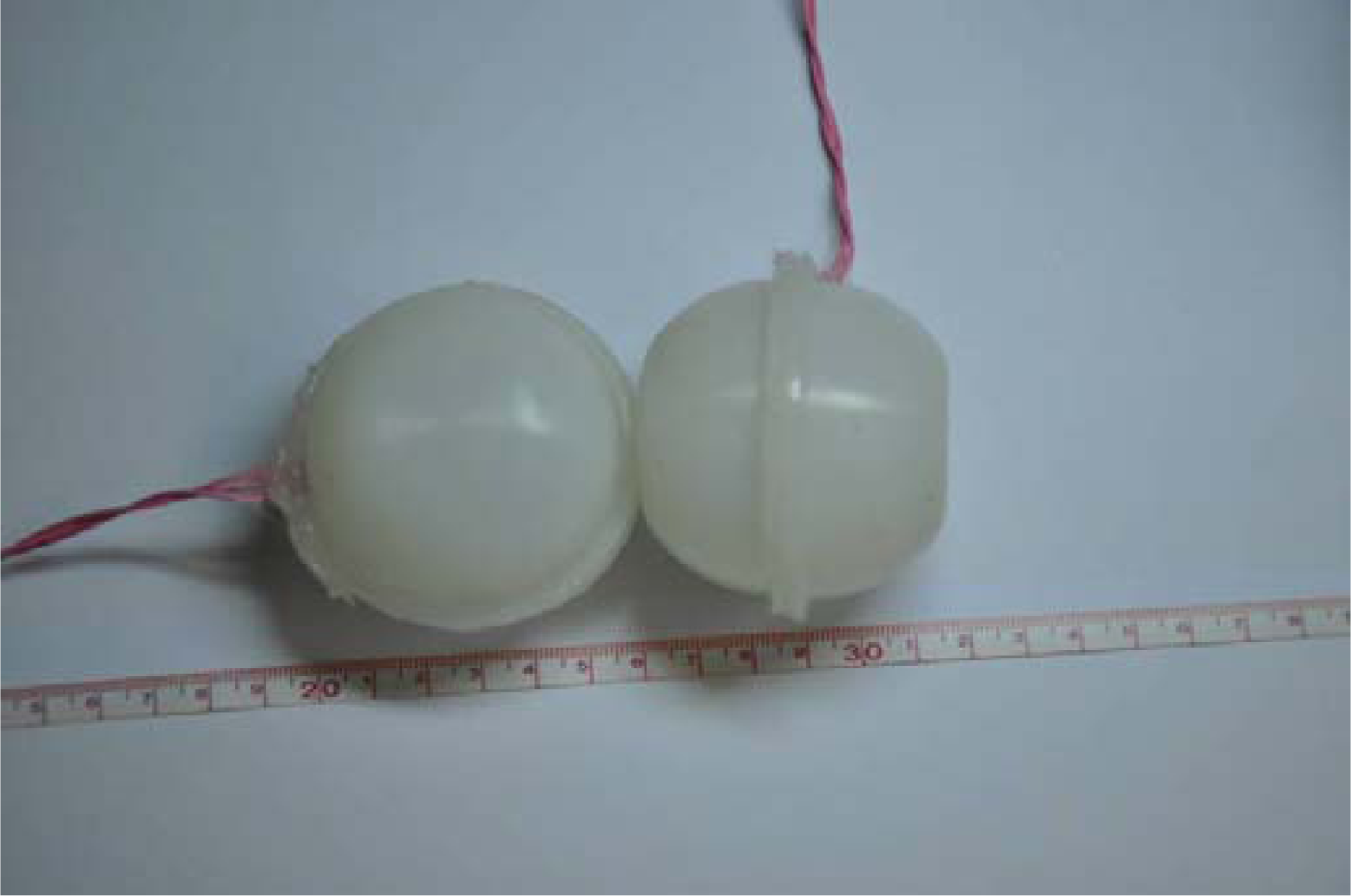
The plantar force sensing unit was designed by encasing the fabricated pressure sensor into a flexible spherical bladder made of silicon rubber. Silicon rubber is used because it exhibits good stability, self-healing and high breakdown field strength [<xref ref-type="bibr" rid="b29-sensors-12-16628">29</xref>]. The spherical bladder was designed with flanging and fabricated by injection molding process. This was helpful to improve the operating reliability of the sensing unit by increasing the adhesive area and strength.</p>
<p>To protect the pressure sensor and increase the measuring range of the sensing unit, silicon oil is filled into the silicon rubber bladder as pressure transfer medium, because it has some advantages over other materials such as small compressibility, high purity and high electric resistivity [<xref ref-type="bibr" rid="b30-sensors-12-16628">30</xref>]. This proposal provides a flexible interface between the human tissue and the pressure sensor while maintaining high measurement accuracy.</p>
<p>In the plantar sensing unit, electrical connection for power supply and signal transmission is required without any leakage of silicon oil. A lead slot is carefully designed on the edge of the spherical bladder to solve this problem. A special wire coated with rubber is used to transmit the power and signal, for it will provide good adhesive properties matching with the silicon rubber. Then, the bladder is bonded and sealed by silicon rubber adhesive. Prototypes of the plantar force sensing units are shown in <xref ref-type="fig" rid="f9-sensors-12-16628">Figure 9</xref>.</p></sec>
<sec sec-type="methods">
<label>3.3</label>
<title>Design of the Measurement System</title>
<p>
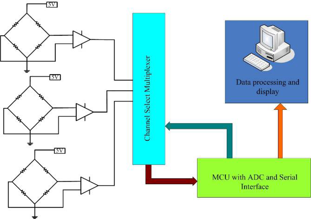
A conditioning circuit is designed to acquire, amplify and store the plantar force signal. The schematic diagram of the conditioning circuit is given in <xref ref-type="fig" rid="f10-sensors-12-16628">Figure 10</xref>. Outputs of the three pressure sensors are amplified separately, and then a multiplexer is used to switch channel to an analog digital conversion device. Finally, the digital signal of plantar force is sent to a computer by the serial port for display and storage.</p>
<p>
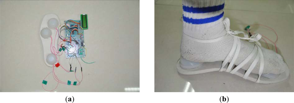
Three plantar force sensing units and the conditioning circuit are assembled into a sole to build up the plantar force measurement system. Three units are placed under the toe, sole and heel respectively according to the anatomy of the human foot. The designed plantar force measurement system is shown in <xref ref-type="fig" rid="f11-sensors-12-16628">Figure 11(a)</xref>. <xref ref-type="fig" rid="f11-sensors-12-16628">Figure 11(b)</xref> shows the simple setup of the plantar force measurement.</p></sec></sec>
<sec sec-type="results">
<label>4.</label>
<title>Experimental Setup and Results</title>
<p>
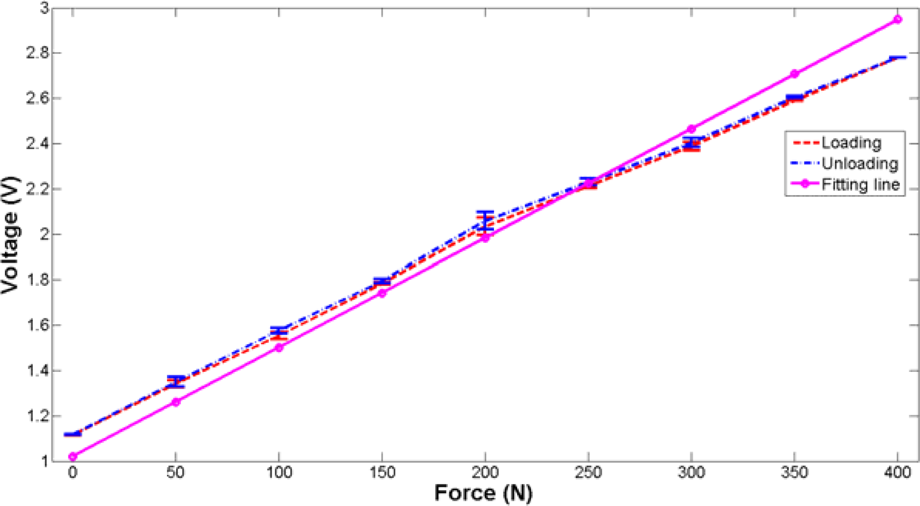
Static and dynamic tests are performed to evaluate the performance of the designed plantar force measurement system. The static characteristics of the sensing unit were investigated by an electronic universal material testing machine (UTM6104, Shenzhen Suns Technology Stock Co. Ltd., Shenzhen, China). The sensing unit was placed on the worktable of the testing machine. The applied force rose from 0 N to 400 N and decreased to 0 N in one test. The maximum applied force was determined according to the previous test parameters [<xref ref-type="bibr" rid="b31-sensors-12-16628">31</xref>]. Tests were repeated four times and the average value of output voltage was calculated. The experimental data is fitted with the Least Square Method. <xref ref-type="fig" rid="f12-sensors-12-16628">Figure 12</xref> shows the fitting results of the output voltage as a function of applied force with standard deviation denoted. It can be obviously seen that the fabricated plantar force sensing unit exhibits an average sensitivity (the slope) of 4.17 mV/N. Hysteresis is 1.26%, which is mainly due to the viscoelasticity of the silicon rubber. The linearity and repeatability are 8.71% and 0.71%, respectively. The nonlinearity is mainly caused by the viscous materials used in the sensing unit. To investigate the creep of the sensing unit, a constant force of 200 N is exerted. The output of the sensing unit is recorded over an hour to evaluate the creep as shown in <xref ref-type="fig" rid="f13-sensors-12-16628">Figure 13</xref>. As to the creep value, the calculated maximum error over an hour is about 6.2%.</p>
<p>The dynamic test is implemented by imposing a step force that is generated by rapidly loading a 15 kg weight on the bladder. <xref ref-type="fig" rid="f14-sensors-12-16628">Figure 14</xref> shows the dynamic response of the sensing unit to the step force. The peak time and oscillation period of the signal are obtained by observing the curve. The response frequency of the designed sensing unit is about 9.6 Hz. This low frequency may be mainly induced by low stiffness and high internal damping of the materials used in the prototype. However, this frequency range is enough for normal gait detection based on the results reported in [<xref ref-type="bibr" rid="b13-sensors-12-16628">13</xref>].</p>
<p><xref ref-type="table" rid="t1-sensors-12-16628">Table 1</xref> compares the characteristics of the designed plantar force sensing unit with one commercial flexible force sensor. It is obvious that the plantar force sensor presented in this paper has better performances.</p>
<p>
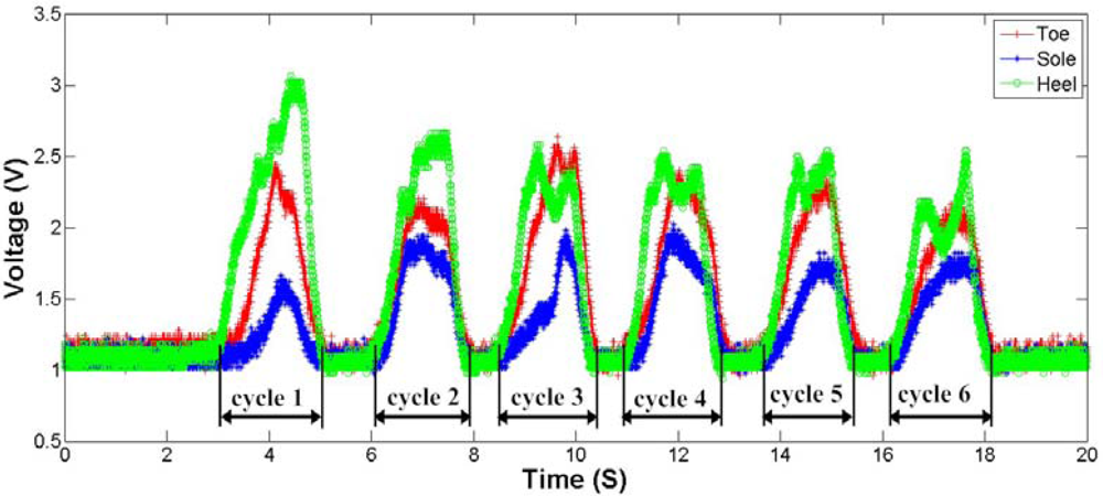
Finally, a simple practical experiment of plantar force measurement is carried out in order to validate the designed system. The plantar force measurement sole is placed and fastened under the foot of a subject. The subject repeats the mark time action considering the motion is restricted by the signal cable. The actions were repeated randomly for six times in this measurement. <xref ref-type="fig" rid="f15-sensors-12-16628">Figure 15</xref> shows the output curves of the three sensing units. The maximum plantar force appears beneath the heel, and minimum force locates under the sole. By analysis the output signal of three sensing units, we can collect the useful information of the plantar force without difficulty. These data can be further processed and used for clinical purposes, such as gait detection and so on.</p></sec>
<sec sec-type="conclusions">
<label>5.</label>
<title>Conclusions</title>
<p>This paper presents the development of a plantar force measurement system prototype for human gait detection. The proposed prototype consists of three plantar force sensing units and a conditioning circuit for data processing and acquisition. The sensing unit uses a MEMS-based pressure sensor as the sensing element and a silicon oil-filled bladder as the pressure transmission medium. The dimensions of the pressure sensor chip are specified by theoretical modeling and FEM size optimization. The experimental results show that the sensing unit features high repeatability (≤0.71%), low hysteresis (≤1.26%), small creep (≤6.2%), and acceptable linearity (≤8.71%). The measured dynamic response frequency is about 9.6 Hz, which is enough for normal human gait detection. Practical measurements show that the proposed system can reflect the foot motion in mark time action. The developed plantar force measurement system prototype combines the advantages of MEMS-Based sensors and flexible interface of rubber bladder, confirming the feasibility of embedding a micro pressure sensor chip into a flexible bladder to detect the human gait. Future work will be focused on the package optimization to improve the structural compactness, and the incorporation into a wireless sensor network for better and wider practical applications has also been be put on the agenda.</p></sec></body>
<back>
<ack>
<p>This work is supported by the Program for Chang Jiang Scholars and Innovative Research Team in University of China (IRT1033).</p></ack>
<ref-list>
<title>References</title>
<ref id="b1-sensors-12-16628"><label>1.</label><citation citation-type="journal"><person-group person-group-type="author"><name><surname>Kong</surname><given-names>K.</given-names></name><name><surname>Jeon</surname><given-names>D.</given-names></name></person-group><article-title>Design and control of an exoskeleton for the elderly and patients</article-title><source>IEEE/ASME Trans. Mechatron</source><year>2006</year><volume>11</volume><fpage>428</fpage><lpage>432</lpage><pub-id pub-id-type="doi">10.1109/TMECH.2006.878550</pub-id></citation></ref>
<ref id="b2-sensors-12-16628"><label>2.</label><citation citation-type="journal"><person-group person-group-type="author"><name><surname>Ferris</surname><given-names>D.P.</given-names></name><name><surname>Czerniecki</surname><given-names>J.M.</given-names></name><name><surname>Hannaford</surname><given-names>B.</given-names></name></person-group><article-title>An ankle-foot orthosis powered by artificial pneumatic muscles</article-title><source>J. Appl. Biomech</source><year>2005</year><volume>21</volume><fpage>189</fpage><lpage>197</lpage><pub-id pub-id-type="pmid">16082019</pub-id></citation></ref>
<ref id="b3-sensors-12-16628"><label>3.</label><citation citation-type="journal"><person-group person-group-type="author"><name><surname>Kong</surname><given-names>K.</given-names></name><name><surname>Tomizuka</surname><given-names>M.</given-names></name></person-group><article-title>A gait monitoring system based on air pressure sensors embedded in a shoe</article-title><source>IEEE/ASME Trans. Mechatron</source><year>2009</year><volume>14</volume><fpage>358</fpage><lpage>370</lpage><pub-id pub-id-type="doi">10.1109/TMECH.2008.2008803</pub-id></citation></ref>
<ref id="b4-sensors-12-16628"><label>4.</label><citation citation-type="journal"><person-group person-group-type="author"><name><surname>Tao</surname><given-names>W.</given-names></name><name><surname>Liu</surname><given-names>T.</given-names></name><name><surname>Zheng</surname><given-names>R.</given-names></name><name><surname>Feng</surname><given-names>H.</given-names></name></person-group><article-title>Gait analysis using wearable sensors</article-title><source>Sensors</source><year>2012</year><volume>12</volume><fpage>2255</fpage><lpage>2283</lpage><pub-id pub-id-type="doi">10.3390/s120202255</pub-id><pub-id pub-id-type="pmid">22438763</pub-id></citation></ref>
<ref id="b5-sensors-12-16628"><label>5.</label><citation citation-type="journal"><person-group person-group-type="author"><name><surname>Fourchet</surname><given-names>F.</given-names></name><name><surname>Kelly</surname><given-names>L.</given-names></name><name><surname>Horobeanu</surname><given-names>C.</given-names></name><name><surname>Loepelt</surname><given-names>H.</given-names></name><name><surname>Taiar</surname><given-names>R.</given-names></name><name><surname>Millet</surname><given-names>G.P.</given-names></name></person-group><article-title>Comparison of plantar pressure distribution in adolescent runners at low <italic>vs</italic>. high running velocity</article-title><source>Gait Posture</source><year>2012</year><volume>35</volume><fpage>685</fpage><lpage>687</lpage><pub-id pub-id-type="doi">10.1016/j.gaitpost.2011.12.004</pub-id><pub-id pub-id-type="pmid">22205042</pub-id></citation></ref>
<ref id="b6-sensors-12-16628"><label>6.</label><citation citation-type="journal"><person-group person-group-type="author"><name><surname>Willems</surname><given-names>T.M.</given-names></name><name><surname>De Ridder</surname><given-names>R.</given-names></name><name><surname>Roosen</surname><given-names>P.</given-names></name></person-group><article-title>The effect of a long-distance run on plantar pressure distribution during running</article-title><source>Gait Posture</source><year>2012</year><volume>35</volume><fpage>405</fpage><lpage>409</lpage><pub-id pub-id-type="doi">10.1016/j.gaitpost.2011.10.362</pub-id><pub-id pub-id-type="pmid">22153665</pub-id></citation></ref>
<ref id="b7-sensors-12-16628"><label>7.</label><citation citation-type="journal"><person-group person-group-type="author"><name><surname>Trojnacki</surname><given-names>M.T.</given-names></name><name><surname>Zielińska</surname><given-names>T.</given-names></name></person-group><article-title>Motion synthesis and force distribution analysis for a biped robot</article-title><source>Acta Bioengin. Biomech</source><year>2011</year><volume>13</volume><fpage>45</fpage><lpage>56</lpage></citation></ref>
<ref id="b8-sensors-12-16628"><label>8.</label><citation citation-type="confproc"><person-group person-group-type="author"><name><surname>Huang</surname><given-names>B.</given-names></name><name><surname>Chen</surname><given-names>M.</given-names></name><name><surname>Shi</surname><given-names>X.</given-names></name><name><surname>Xu</surname><given-names>Y.</given-names></name></person-group><article-title>Gait Event Detection with Intelligent Shoes</article-title><conf-name>Proceedings of the International Conference on Information Acquisition</conf-name><conf-loc>Seogwipo-si, Korea</conf-loc><conf-date>8–11 July 2007</conf-date><fpage>579</fpage><lpage>584</lpage></citation></ref>
<ref id="b9-sensors-12-16628"><label>9.</label><citation citation-type="journal"><person-group person-group-type="author"><name><surname>Bamberg</surname><given-names>S.</given-names></name><name><surname>Benbasat</surname><given-names>A.Y.</given-names></name><name><surname>Scarborough</surname><given-names>D.M.</given-names></name><name><surname>Krebs</surname><given-names>D.E.</given-names></name><name><surname>Paradiso</surname><given-names>J.A.</given-names></name></person-group><article-title>Gait analysis using a shoe-integrated wireless sensor system</article-title><source>IEEE Trans. Inform. Technol. Biomed</source><year>2008</year><volume>12</volume><fpage>413</fpage><lpage>423</lpage><pub-id pub-id-type="doi">10.1109/TITB.2007.899493</pub-id></citation></ref>
<ref id="b10-sensors-12-16628"><label>10.</label><citation citation-type="journal"><person-group person-group-type="author"><name><surname>Sazonov</surname><given-names>E.S.</given-names></name><name><surname>Fulk</surname><given-names>G.</given-names></name><name><surname>Hill</surname><given-names>J.</given-names></name><name><surname>Schutz</surname><given-names>Y.</given-names></name><name><surname>Browning</surname><given-names>R.</given-names></name></person-group><article-title>Monitoring of posture allocations and activities by a shoe-based wearable sensor</article-title><source>IEEE Trans. Biomed. Eng</source><year>2011</year><volume>58</volume><fpage>983</fpage><lpage>990</lpage><pub-id pub-id-type="doi">10.1109/TBME.2010.2046738</pub-id><pub-id pub-id-type="pmid">20403783</pub-id></citation></ref>
<ref id="b11-sensors-12-16628"><label>11.</label><citation citation-type="journal"><person-group person-group-type="author"><name><surname>Saito</surname><given-names>M.</given-names></name><name><surname>Nakajima</surname><given-names>K.</given-names></name><name><surname>Takano</surname><given-names>C.</given-names></name><name><surname>Ohta</surname><given-names>Y.</given-names></name><name><surname>Sugimoto</surname><given-names>C.</given-names></name><name><surname>Ezoe</surname><given-names>R.</given-names></name><name><surname>Sasaki</surname><given-names>K.</given-names></name><name><surname>Hosaka</surname><given-names>H.</given-names></name><name><surname>Ifukube</surname><given-names>T.</given-names></name><name><surname>Ino</surname><given-names>S.</given-names></name></person-group><article-title>An in-shoe device to measure plantar pressure during daily human activity</article-title><source>Med. Eng. Phys</source><year>2011</year><volume>33</volume><fpage>638</fpage><lpage>645</lpage><pub-id pub-id-type="doi">10.1016/j.medengphy.2011.01.001</pub-id><pub-id pub-id-type="pmid">21310644</pub-id></citation></ref>
<ref id="b12-sensors-12-16628"><label>12.</label><citation citation-type="journal"><person-group person-group-type="author"><name><surname>Lee</surname><given-names>N.</given-names></name><name><surname>Goonetilleke</surname><given-names>R.</given-names></name><name><surname>Cheung</surname><given-names>Y.</given-names></name><name><surname>So</surname><given-names>G.M.Y.</given-names></name></person-group><article-title>A flexible encapsulated MEMS pressure sensor system for biomechanical applications</article-title><source>Microsyst. Technol</source><year>2001</year><volume>7</volume><fpage>55</fpage><lpage>62</lpage><pub-id pub-id-type="doi">10.1007/s005420100092</pub-id></citation></ref>
<ref id="b13-sensors-12-16628"><label>13.</label><citation citation-type="journal"><person-group person-group-type="author"><name><surname>Urry</surname><given-names>S.</given-names></name></person-group><article-title>Plantar pressure-measurement sensors</article-title><source>Meas. Sci. Technol</source><year>1999</year><volume>10</volume><fpage>16</fpage><lpage>32</lpage><pub-id pub-id-type="doi">10.1088/0957-0233/10/1/017</pub-id></citation></ref>
<ref id="b14-sensors-12-16628"><label>14.</label><citation citation-type="journal"><person-group person-group-type="author"><name><surname>Hsiao</surname><given-names>H.</given-names></name><name><surname>Guan</surname><given-names>J.</given-names></name><name><surname>Weatherly</surname><given-names>M.</given-names></name></person-group><article-title>Accuracy and precision of two in-shoe pressure measurement systems</article-title><source>Ergonomics</source><year>2002</year><volume>45</volume><fpage>537</fpage><lpage>555</lpage><pub-id pub-id-type="doi">10.1080/00140130210136963</pub-id><pub-id pub-id-type="pmid">12167198</pub-id></citation></ref>
<ref id="b15-sensors-12-16628"><label>15.</label><citation citation-type="confproc"><person-group person-group-type="author"><name><surname>Chedevergne</surname><given-names>F.</given-names></name><name><surname>Faivre</surname><given-names>A.</given-names></name><name><surname>Dahan</surname><given-names>M.</given-names></name></person-group><article-title>Development of a Mechatronical Device to Measure Plantar Pressure for Medical Prevention of Gait Issues</article-title><conf-name>Proceedings of the IEEE International Conference on Mechatronics and Automation</conf-name><conf-loc>Luoyang, China</conf-loc><conf-date>25–28 June 2006</conf-date></citation></ref>
<ref id="b16-sensors-12-16628"><label>16.</label><citation citation-type="confproc"><person-group person-group-type="author"><name><surname>De Rossi</surname><given-names>S.M.M.</given-names></name><name><surname>Lenzi</surname><given-names>T.</given-names></name><name><surname>Vitiello</surname><given-names>N.</given-names></name><name><surname>Donati</surname><given-names>M.</given-names></name><name><surname>Persichetti</surname><given-names>A.</given-names></name><name><surname>Giovacchini</surname><given-names>F.</given-names></name><name><surname>Vecchi</surname><given-names>F.</given-names></name><name><surname>Carrozza</surname><given-names>M.C.</given-names></name></person-group><article-title>Development of an In-Shoe Pressure-Sensitive Device for Gait Analysis</article-title><conf-name>Proceedings of 2011 Annual International Conference of the IEEE Engineering in Medicine and Biology Society</conf-name><conf-loc>Boston, MA, USA</conf-loc><conf-date>30 August–3 September 2011</conf-date></citation></ref>
<ref id="b17-sensors-12-16628"><label>17.</label><citation citation-type="journal"><person-group person-group-type="author"><name><surname>Shu</surname><given-names>L.</given-names></name><name><surname>Hua</surname><given-names>T.</given-names></name><name><surname>Wang</surname><given-names>Y.</given-names></name><name><surname>Li</surname><given-names>Q.</given-names></name><name><surname>Feng</surname><given-names>D.D.</given-names></name><name><surname>Tao</surname><given-names>X.</given-names></name></person-group><article-title>In-Shoe plantar pressure measurement and analysis system based on fabric pressure sensing array</article-title><source>IEEE Trans. Inform. Technol. Biomed</source><year>2010</year><volume>14</volume><fpage>767</fpage><lpage>775</lpage><pub-id pub-id-type="doi">10.1109/TITB.2009.2038904</pub-id></citation></ref>
<ref id="b18-sensors-12-16628"><label>18.</label><citation citation-type="journal"><person-group person-group-type="author"><name><surname>Kärki</surname><given-names>S.</given-names></name><name><surname>Lekkala</surname><given-names>J.</given-names></name><name><surname>Kuokkanen</surname><given-names>H.</given-names></name><name><surname>Halttunen</surname><given-names>J.</given-names></name></person-group><article-title>Development of a piezoelectric polymer film sensor for plantar normal and shear stress measurements</article-title><source>Sens. Actuators A Phys</source><year>2009</year><volume>154</volume><fpage>57</fpage><lpage>64</lpage><pub-id pub-id-type="doi">10.1016/j.sna.2009.07.010</pub-id></citation></ref>
<ref id="b19-sensors-12-16628"><label>19.</label><citation citation-type="journal"><person-group person-group-type="author"><name><surname>Dobrzynska</surname><given-names>J.A.</given-names></name><name><surname>Gijs</surname><given-names>M.A.M.</given-names></name></person-group><article-title>Flexible polyimide-based force sensor</article-title><source>Sens. Actuators A Phys</source><year>2011</year><volume>173</volume><fpage>127</fpage><lpage>135</lpage></citation></ref>
<ref id="b20-sensors-12-16628"><label>20.</label><citation citation-type="journal"><person-group person-group-type="author"><name><surname>Petropoulos</surname><given-names>A.</given-names></name><name><surname>Kaltsas</surname><given-names>G.</given-names></name><name><surname>Goustouridis</surname><given-names>D.</given-names></name><name><surname>Gogolides</surname><given-names>E.</given-names></name></person-group><article-title>A flexible capacitive device for pressure and tactile sensing</article-title><source>Procedia Chem</source><year>2009</year><volume>1</volume><fpage>867</fpage><lpage>870</lpage><pub-id pub-id-type="doi">10.1016/j.proche.2009.07.216</pub-id></citation></ref>
<ref id="b21-sensors-12-16628"><label>21.</label><citation citation-type="journal"><person-group person-group-type="author"><name><surname>Lei</surname><given-names>K.F.</given-names></name><name><surname>Lee</surname><given-names>K.F.</given-names></name><name><surname>Lee</surname><given-names>M.Y.</given-names></name></person-group><article-title>Development of a flexible PDMS capacitive pressure sensor for plantar pressure measurement</article-title><source>Microelectron. Eng</source><year>2012</year><volume>99</volume><fpage>1</fpage><lpage>5</lpage><pub-id pub-id-type="doi">10.1016/j.mee.2012.06.005</pub-id></citation></ref>
<ref id="b22-sensors-12-16628"><label>22.</label><citation citation-type="confproc"><person-group person-group-type="author"><name><surname>Wheeler</surname><given-names>J.</given-names></name><name><surname>Rohrer</surname><given-names>B.</given-names></name><name><surname>Kholwadwala</surname><given-names>D.</given-names></name><name><surname>Buerger</surname><given-names>S.</given-names></name><name><surname>Givler</surname><given-names>R.</given-names></name><name><surname>Neely</surname><given-names>J.</given-names></name><name><surname>Hobart</surname><given-names>C.</given-names></name><name><surname>Galambos</surname><given-names>P.</given-names></name></person-group><article-title>In-Sole MEMS Pressure Sensing for a Lower-Extremity Exoskeleton</article-title><conf-name>Proceedings of the First IEEE/RAS-EMBS International Conferenceon Biomedical Robotics and Biomechatronics</conf-name><conf-loc>Pisa, Italy</conf-loc><conf-date>20–22 February 2006</conf-date></citation></ref>
<ref id="b23-sensors-12-16628"><label>23.</label><citation citation-type="book"><person-group person-group-type="author"><name><surname>Moaveni</surname><given-names>S.</given-names></name></person-group><source>Finite Element Analysis: Theory and Application with ANSYS (Simplified Chinese Edition)</source><edition>2nd ed.</edition><publisher-name>Pearson Education Asia Limited</publisher-name><publisher-loc>Hong Kong</publisher-loc><year>2005</year><fpage>557</fpage><lpage>566</lpage></citation></ref>
<ref id="b24-sensors-12-16628"><label>24.</label><citation citation-type="journal"><person-group person-group-type="author"><name><surname>Tian</surname><given-names>B.</given-names></name><name><surname>Zhao</surname><given-names>Y.</given-names></name><name><surname>Jiang</surname><given-names>Z.</given-names></name><name><surname>Zhang</surname><given-names>L.</given-names></name><name><surname>Liao</surname><given-names>N.</given-names></name><name><surname>Liu</surname><given-names>Y.</given-names></name><name><surname>Meng</surname><given-names>C.</given-names></name></person-group><article-title>Fabrication and structural design of micro pressure sensors for tire pressure measurement systems (TPMS)</article-title><source>Sensors</source><year>2009</year><volume>9</volume><fpage>1382</fpage><lpage>1393</lpage><pub-id pub-id-type="doi">10.3390/s90301382</pub-id><pub-id pub-id-type="pmid">22573960</pub-id></citation></ref>
<ref id="b25-sensors-12-16628"><label>25.</label><citation citation-type="journal"><person-group person-group-type="author"><name><surname>Celler</surname><given-names>G.K.</given-names></name><name><surname>Cristoloveanu</surname><given-names>S.</given-names></name></person-group><article-title>Frontiers of silicon-on-insulator</article-title><source>J. Appl. Phys</source><year>2003</year><volume>93</volume><fpage>4955</fpage><lpage>4978</lpage><pub-id pub-id-type="doi">10.1063/1.1558223</pub-id></citation></ref>
<ref id="b26-sensors-12-16628"><label>26.</label><citation citation-type="journal"><person-group person-group-type="author"><name><surname>Darrin</surname><given-names>A.G.</given-names></name><name><surname>Osiander</surname><given-names>R.</given-names></name></person-group><article-title>MEMS packaging materials</article-title><source>MEMS Reference Shelf</source><year>2011</year><pub-id pub-id-type="doi">10.1007/978-0-387-47318-5_12</pub-id></citation></ref>
<ref id="b27-sensors-12-16628"><label>27.</label><citation citation-type="thesis"><person-group person-group-type="author"><name><surname>Zheng</surname><given-names>P.</given-names></name></person-group><article-title>High Temperature Electronics Packaging Processes and Materials Development</article-title><comment>Ph.D. Thesis</comment><publisher-name>Auburn University</publisher-name><publisher-loc>Auburn, AL, USA</publisher-loc><year>2010</year></citation></ref>
<ref id="b28-sensors-12-16628"><label>28.</label><citation citation-type="journal"><person-group person-group-type="author"><name><surname>Chen</surname><given-names>T.</given-names></name><name><surname>Zhang</surname><given-names>Z.H.</given-names></name><name><surname>Ren</surname><given-names>T.L.</given-names></name><name><surname>Miao</surname><given-names>G.J.</given-names></name><name><surname>Zhou</surname><given-names>C.J.</given-names></name><name><surname>Lin</surname><given-names>H.W.</given-names></name><name><surname>Liu</surname><given-names>L.T.</given-names></name></person-group><article-title>A novel dual-functional MEMS sensor integrating both pressure and temperature units</article-title><source>J. Semicond.</source><year>2010</year><pub-id pub-id-type="doi">10.1088/1674-4926/31/7/074013</pub-id></citation></ref>
<ref id="b29-sensors-12-16628"><label>29.</label><citation citation-type="journal"><person-group person-group-type="author"><name><surname>Leineweber</surname><given-names>M.</given-names></name><name><surname>Pelz</surname><given-names>G.</given-names></name><name><surname>Schmidt</surname><given-names>M.</given-names></name><name><surname>Kappert</surname><given-names>H.</given-names></name><name><surname>Zimmer</surname><given-names>G.</given-names></name></person-group><article-title>New tactile sensor chip with silicone rubber cover</article-title><source>Sens. Actuators A Phys</source><year>2000</year><volume>84</volume><fpage>236</fpage><lpage>245</lpage><pub-id pub-id-type="doi">10.1016/S0924-4247(00)00310-1</pub-id></citation></ref>
<ref id="b30-sensors-12-16628"><label>30.</label><citation citation-type="journal"><person-group person-group-type="author"><name><surname>Jevtić</surname><given-names>M.M.</given-names></name><name><surname>Smiljanić</surname><given-names>M.A.</given-names></name></person-group><article-title>Diagnostic of silicon piezoresistive pressure sensors by low frequency noise measurements</article-title><source>Sens. Actuators A Phys</source><year>2008</year><volume>144</volume><fpage>267</fpage><lpage>274</lpage><pub-id pub-id-type="doi">10.1016/j.sna.2008.02.002</pub-id></citation></ref>
<ref id="b31-sensors-12-16628"><label>31.</label><citation citation-type="journal"><person-group person-group-type="author"><name><surname>Nevill</surname><given-names>A.</given-names></name><name><surname>Pepper</surname><given-names>M.</given-names></name><name><surname>Whiting</surname><given-names>M.</given-names></name></person-group><article-title>In-Shoe foot pressure measurement system utilising piezoelectric film transducers</article-title><source>Med. Biol. Eng. Comput</source><year>1995</year><volume>33</volume><fpage>76</fpage><lpage>81</lpage><pub-id pub-id-type="doi">10.1007/BF02522950</pub-id><pub-id pub-id-type="pmid">7616786</pub-id></citation></ref>
<ref id="b32-sensors-12-16628"><label>32.</label><citation citation-type="thesis"><person-group person-group-type="author"><name><surname>Wu</surname><given-names>Y.Q.</given-names></name></person-group><article-title>Development of an Approach for Interface Pressure Measurement and Analysis for Study of Sitting</article-title><comment>MS. Thesis</comment><publisher-name>National University of Singapore</publisher-name><publisher-loc>Singapore</publisher-loc><year>2010</year></citation></ref></ref-list>
<sec sec-type="display-objects">
<title>Figures and Table</title>
<fig id="f1-sensors-12-16628" position="float">
<label>Figure 1.</label>
<caption>
<p>Conceptual design model of the proposed micro pressure sensor.</p></caption>
<graphic xlink:href="sensors-12-16628f1.gif"/></fig>
<fig id="f2-sensors-12-16628" position="float">
<label>Figure 2.</label>
<caption>
<p>Calculated strain <italic>versus</italic> the diagram size and thickness.</p></caption>
<graphic xlink:href="sensors-12-16628f2.gif"/></fig>
<fig id="f3-sensors-12-16628" position="float">
<label>Figure 3.</label>
<caption>
<p>Meshed ANSYS model with the applied boundary conditions.</p></caption>
<graphic xlink:href="sensors-12-16628f3.gif"/></fig>
<fig id="f4-sensors-12-16628" position="float">
<label>Figure 4.</label>
<caption>
<p>State variable change curve with the iterations.</p></caption>
<graphic xlink:href="sensors-12-16628f4.gif"/></fig>
<fig id="f5-sensors-12-16628" position="float">
<label>Figure 5.</label>
<caption>
<p>Analytical results of the quarter model of the sensor chip based on ANSYS.</p></caption>
<graphic xlink:href="sensors-12-16628f5.gif"/></fig>
<fig id="f6-sensors-12-16628" position="float">
<label>Figure 6.</label>
<caption>
<p>Fabrication process steps of the micro pressure sensor.</p></caption>
<graphic xlink:href="sensors-12-16628f6.gif"/></fig>
<fig id="f7-sensors-12-16628" position="float">
<label>Figure 7.</label>
<caption>
<p>Photograph of a fabricated micro pressure sensor chip.</p></caption>
<graphic xlink:href="sensors-12-16628f7.gif"/></fig>
<fig id="f8-sensors-12-16628" position="float">
<label>Figure 8.</label>
<caption>
<p>Photograph of a micro pressure sensor after package.</p></caption>
<graphic xlink:href="sensors-12-16628f8.gif"/></fig>
<fig id="f9-sensors-12-16628" position="float">
<label>Figure 9.</label>
<caption>
<p>Photograph of plantar force sensing unit.</p></caption>
<graphic xlink:href="sensors-12-16628f9.gif"/></fig>
<fig id="f10-sensors-12-16628" position="float">
<label>Figure 10.</label>
<caption>
<p>Schematic diagram of the conditioning circuit.</p></caption>
<graphic xlink:href="sensors-12-16628f10.gif"/></fig>
<fig id="f11-sensors-12-16628" position="float">
<label>Figure 11.</label>
<caption>
<p>Pictures of the plantar force measurement test. (<bold>a</bold>) The designed plantar force measurement system; (<bold>b</bold>) The scene of the plantar force measurement.</p></caption>
<graphic xlink:href="sensors-12-16628f11.gif"/></fig>
<fig id="f12-sensors-12-16628" position="float">
<label>Figure 12.</label>
<caption>
<p>The static performance of the designed plantar force sensor.</p></caption>
<graphic xlink:href="sensors-12-16628f12.gif"/></fig>
<fig id="f13-sensors-12-16628" position="float">
<label>Figure 13.</label>
<caption>
<p>The creep of the designed plantar force sensor for 1 h.</p></caption>
<graphic xlink:href="sensors-12-16628f13.gif"/></fig>
<fig id="f14-sensors-12-16628" position="float">
<label>Figure 14.</label>
<caption>
<p>Response of the sensor to a step force.</p></caption>
<graphic xlink:href="sensors-12-16628f14.gif"/></fig>
<fig id="f15-sensors-12-16628" position="float">
<label>Figure 15.</label>
<caption>
<p>Voltage time waveform obtained from the plantar force measurement.</p></caption>
<graphic xlink:href="sensors-12-16628f15.gif"/></fig>
<table-wrap id="t1-sensors-12-16628" position="float">
<label>Table 1.</label>
<caption>
<p>Comparisons with a commercial sensor.</p></caption>
<table frame="hsides" rules="groups">
<thead>
<tr>
<th align="left" valign="bottom"><bold>Device</bold></th>
<th align="center" valign="bottom"><bold>Linearity</bold></th>
<th align="center" valign="bottom"><bold>Hysteresis</bold></th>
<th align="center" valign="bottom"><bold>Repeatability</bold></th>
<th align="center" valign="bottom"><bold>Frequency</bold></th>
<th align="center" valign="bottom"><bold>Creep</bold></th></tr></thead>
<tbody>
<tr>
<td align="left" valign="top">Flexiforce sensor [<xref ref-type="bibr" rid="b32-sensors-12-16628">32</xref>]</td>
<td align="center" valign="top">≤±10%</td>
<td align="center" valign="top">≤15%</td>
<td align="center" valign="top">≤5%</td>
<td align="center" valign="top">Not available</td>
<td align="center" valign="top">&lt;15%</td></tr>
<tr>
<td align="left" valign="top">This works</td>
<td align="center" valign="top">8.71%</td>
<td align="center" valign="top">1.26%</td>
<td align="center" valign="top">0.71%</td>
<td align="center" valign="top">9.6 Hz</td>
<td align="center" valign="top">6.2%</td></tr></tbody></table></table-wrap></sec></back></article>
