<?xml version="1.0" encoding="UTF-8"?>
<!DOCTYPE article PUBLIC "-//NLM//DTD Journal Publishing DTD v2.3 20070202//EN" "journalpublishing.dtd">
<article xmlns:mml="http://www.w3.org/1998/Math/MathML" xmlns:xlink="http://www.w3.org/1999/xlink" xml:lang="en" article-type="research-article">
<front>
<journal-meta>
<journal-id journal-id-type="nlm-ta">Sensors</journal-id>
<journal-title>Sensors</journal-title>
<issn pub-type="epub">1424-8220</issn>
<publisher>
<publisher-name>Molecular Diversity Preservation International (MDPI)</publisher-name></publisher></journal-meta>
<article-meta>
<article-id pub-id-type="doi">10.3390/s110706991</article-id>
<article-id pub-id-type="publisher-id">sensors-11-06991</article-id>
<article-categories>
<subj-group>
<subject>Article</subject></subj-group></article-categories>
<title-group>
<article-title>A Celestial Assisted INS Initialization Method for Lunar Explorers</article-title></title-group>
<contrib-group>
<contrib contrib-type="author">
<name><surname>Ning</surname><given-names>Xiaolin</given-names></name><xref ref-type="corresp" rid="c1-sensors-11-06991"><sup>*</sup></xref></contrib>
<contrib contrib-type="author">
<name><surname>Wang</surname><given-names>Longhua</given-names></name></contrib>
<contrib contrib-type="author">
<name><surname>Wu</surname><given-names>Weiren</given-names></name></contrib>
<contrib contrib-type="author">
<name><surname>Fang</surname><given-names>Jiancheng</given-names></name></contrib>
<aff id="af1-sensors-11-06991">School of Instrumentation Science &amp; Opto-electronics Engineering, BeiHang University (BUAA), Beijing 100191, China; E-Mails: <email>beihang456wlh@126.com</email> (L.W.); <email>wuwr2002@vip.sina.com</email> (W.W.); <email>fangjiancheng@buaa.edu.cn</email> (J.F.)</aff></contrib-group>
<author-notes>
<corresp id="c1-sensors-11-06991">
<label>*</label>Author to whom correspondence should be addressed; E-Mail: <email>ningxiaolin@buaa.edu.cn</email>; Tel.: +86-10-8233-9464; Fax: +86-10-8231-6813.</corresp></author-notes>
<pub-date pub-type="collection">
<year>2011</year></pub-date>
<pub-date pub-type="epub">
<day>4</day>
<month>7</month>
<year>2011</year></pub-date>
<volume>11</volume>
<issue>7</issue>
<fpage>6991</fpage>
<lpage>7003</lpage>
<history>
<date date-type="received">
<day>8</day>
<month>5</month>
<year>2011</year></date>
<date date-type="rev-recd">
<day>24</day>
<month>6</month>
<year>2011</year></date>
<date date-type="accepted">
<day>26</day>
<month>6</month>
<year>2011</year></date></history>
<permissions>
<copyright-statement>© 2011 by the authors; licensee MDPI, Basel, Switzerland.</copyright-statement>
<copyright-year>2011</copyright-year>
<license>
<p>This article is an open access article distributed under the terms and conditions of the Creative Commons Attribution license (http://creativecommons.org/licenses/by/3.0/).</p></license></permissions>
<abstract>
<p>The second and third phases of the Chinese Lunar Exploration Program (CLEP) are planning to achieve Moon landing, surface exploration and automated sample return. In these missions, the inertial navigation system (INS) and celestial navigation system (CNS) are two indispensable autonomous navigation systems which can compensate for limitations in the ground based navigation system. The accurate initialization of the INS and the precise calibration of the CNS are needed in order to achieve high navigation accuracy. Neither the INS nor the CNS can solve the above problems using the ground controllers or by themselves on the lunar surface. However, since they are complementary to each other, these problems can be solved by combining them together. A new celestial assisted INS initialization method is presented, in which the initial position and attitude of the explorer as well as the inertial sensors’ biases are estimated by aiding the INS with celestial measurements. Furthermore, the systematic error of the CNS is also corrected by the help of INS measurements. Simulations show that the maximum error in position is 300 m and in attitude 40″, which demonstrates this method is a promising and attractive scheme for explorers on the lunar surface.</p></abstract>
<kwd-group>
<kwd>lunar exploration</kwd>
<kwd>autonomous initialization</kwd>
<kwd>inertial navigation</kwd>
<kwd>celestial navigation</kwd></kwd-group></article-meta></front>
<body>
<sec sec-type="intro">
<label>1.</label>
<title>Introduction</title>
<p>The Moon is the only natural satellite of Earth. There is great potential to develop new technologies and to make use of the Moon’s valuable resources. Up to now, the Moon has been visited by the explorers of the Soviet Union (SU), the United States (US), the European Space Agency (ESA), Japan (JP), China (CHN) and India (IN). There are many lunar exploration programs currently happening or being planned.</p>
<p>China’s lunar exploration is a three-phase mission. In phases I and II, China launched its first and second lunar probes, Chang’e-1 and Chang’e-2, which have successfully finished their missions and obtained 3D images of the lunar surface. In the next few years of the phase II, an unmanned lander, which will carry a lunar rover for the exploration of the Moon’s surface, will softly land on the Moon. In phase III, a return vehicle will collect samples of lunar soil and carry them back to the Earth. In these upcoming missions to the Moon, explorers such as Rovers, Landers, Descenders and Ascenders will use INS and CNS for navigation to compensate for the limited capacity of ground tracking networks. The accuracy of INS and CNS mainly depends upon the accuracy with which these systems are initialized or calibrated, so the accurate initialization of the INS and the precise calibration of the CNS are needed.</p>
<p>The initialization of INS is the process of determining some initial values of the system, such as position, attitude, and sensors biases [<xref ref-type="bibr" rid="b1-sensors-11-06991">1</xref>,<xref ref-type="bibr" rid="b2-sensors-11-06991">2</xref>]. The calibration of CNS is the process of determining and correcting systematic error caused by sensors index error and alignment error [<xref ref-type="bibr" rid="b3-sensors-11-06991">3</xref>]. The initialization of the INS and the calibration of the CNS are difficult problems on the lunar surface and cannot be accomplished by each one alone. However, because INS and CNS have complementary characteristics, their initialization and calibration can be accomplished by the combination of them [<xref ref-type="bibr" rid="b4-sensors-11-06991">4</xref>].</p>
<p>A celestial assisted INS initialization method for explorers on the lunar surface is presented. An unscented Kalman filter is used for fusing information from various INS and CNS sensors. The initial position, attitude as well as biases of INS sensors are estimated effectively and the systematic error of CNS is corrected at the same time. The feasibility of this new method is validated using a ground test bed. Simulations show that the maximum error in position is 300 m and in attitude 40″. These results verify that this method is a promising and attractive scheme for lunar explorers.</p>
<p>This paper is systematized in five sections. After this introduction, the basic principle of INS and CNS is outlined in Section 2. Then the state model and measurement model of this celestial assisted INS initialization method is described in details in Section 3. Simulations in Section 4 demonstrate the performance and conclusions are drawn in Section 5.</p></sec>
<sec>
<label>2.</label>
<title>Inertial Navigation System and Celestial Navigation System</title>
<sec>
<label>2.1.</label>
<title>Reference Frames</title>
<p>Reference frames used in this paper are defined as follows:
<list list-type="order">
<list-item>
<p>The inertial frame (<italic>O<sub>i</sub>X<sub>i</sub>Y<sub>i</sub>Z<sub>i</sub></italic>). As shown in <xref ref-type="fig" rid="f1-sensors-11-06991">Figure 1</xref>, the inertial frame has its origin at the center of the Moon. Its z-axis is normal to the equatorial plane, x-axis is in the equatorial plane and points to the vernal equinox, and the y-axis completes a right-handed orthogonal frame.</p></list-item>
<list-item>
<p>The Moon fixed frame (<italic>O<sub>m</sub>X<sub>m</sub>Y<sub>m</sub>Z<sub>m</sub></italic>). The Moon fixed frame has its origin at the center of the Moon. Its z-axis is normal to the equatorial plane, x-axis is in the equatorial plane and points to the prime meridian (0° longitude), and the y-axis completes a right-handed orthogonal frame.</p></list-item>
<list-item>
<p>The navigation frame (<italic>O<sub>n</sub>X<sub>n</sub>Y<sub>n</sub>Z<sub>n</sub></italic>). The navigation frame is a local vertical frame and has its origin at the location of the explorer. Its x-axis points to the east, the y-axis points to the north, and the z-axis points upward [<xref ref-type="bibr" rid="b5-sensors-11-06991">5</xref>].</p></list-item>
<list-item>
<p>The explorer body frame (<italic>O<sub>b</sub>X<sub>b</sub>Y<sub>b</sub>Z<sub>b</sub></italic>). The explorer body frame is rigidly attached to the explorer and has its origin at the center of the mass of the explorer. Its x-axis is in the symmetry plane of the body pointing at the direction that the explorer moves along. Its z-axis is perpendicular with the symmetrical plane of the body and points down and the y-axis completes a right-handed orthogonal frame. The rotation around these axes defines the angle of roll(<italic>φ</italic>), pitch(<italic>θ</italic>), and yaw(<italic>ψ</italic>), respectively (<xref ref-type="fig" rid="f1-sensors-11-06991">Figure 1</xref>).</p></list-item></list></p></sec>
<sec>
<label>2.2.</label>
<title>The Inertial Navigation System (INS) and Its Initialization</title>
<p>An INS usually includes a navigation computer and an inertial measurement unit (IMU), which typically consists of three orthogonal accelerometers and three orthogonal gyroscopes. By tracking both the current angular velocity and the current linear acceleration of the explorer measured by IMU, the INS determines the linear acceleration of the explorer in the inertial frame. Thus, if the original velocity and position are known, the inertial velocity of the explorer can be obtained by integration of the inertial acceleration, and integration again yields the inertial position. There are two types of inertial navigation systems: platform inertial navigation system and strap-down inertial navigation system (SINS). In the platform inertial navigation system, IMU is mounted on a mechanical platform, which can isolate explorer’s motion and is held in alignment with the expected navigation frame. The main disadvantages of this system are that the mechanical platform is expensive and its moving parts tend to wear out or jam. In the SINS, IMU is mounted rigidly onto the explorer, and a mathematical platform takes the place of the mechanical platform. This reduces the cost and size, increases the reliability by eliminating the moving parts. In this study, SINS is used for navigation of the lunar explorer. The basic equations of inertial navigation in the navigation frame can be simply expressed as follows [<xref ref-type="bibr" rid="b6-sensors-11-06991">6</xref>]:
<disp-formula id="FD1">
<label>(1)</label>
<mml:math display="block">
<mml:mrow>
<mml:mtable columnalign="left">
<mml:mtr columnalign="left">
<mml:mtd columnalign="left">
<mml:mrow>
<mml:mrow>
<mml:mo>{</mml:mo>
<mml:mrow>
<mml:mtable columnalign="left">
<mml:mtr columnalign="left">
<mml:mtd columnalign="left">
<mml:mrow>
<mml:mover accent="true">
<mml:mi>r</mml:mi>
<mml:mo>˙</mml:mo></mml:mover>
<mml:mo> </mml:mo>
<mml:mo>=</mml:mo>
<mml:mo> </mml:mo>
<mml:mi>D</mml:mi>
<mml:mi>v</mml:mi></mml:mrow></mml:mtd></mml:mtr>
<mml:mtr columnalign="left">
<mml:mtd columnalign="left">
<mml:mrow>
<mml:mover accent="true">
<mml:mi>v</mml:mi>
<mml:mo>˙</mml:mo></mml:mover>
<mml:mo> </mml:mo>
<mml:mo>=</mml:mo>
<mml:mo> </mml:mo>
<mml:msubsup>
<mml:mrow>
<mml:mi>R</mml:mi></mml:mrow>
<mml:mi>b</mml:mi>
<mml:mi>n</mml:mi></mml:msubsup>
<mml:mo> </mml:mo>
<mml:msup>
<mml:mrow>
<mml:mi>f</mml:mi></mml:mrow>
<mml:mi>b</mml:mi></mml:msup>
<mml:mo> </mml:mo>
<mml:mo>−</mml:mo>
<mml:mo> </mml:mo>
<mml:mo stretchy="false">(</mml:mo>
<mml:mn>2</mml:mn>
<mml:msubsup>
<mml:mrow>
<mml:mi>w</mml:mi></mml:mrow>
<mml:mrow>
<mml:mi mathvariant="italic">im</mml:mi></mml:mrow>
<mml:mi>n</mml:mi></mml:msubsup>
<mml:mo> </mml:mo>
<mml:mo>+</mml:mo>
<mml:mo> </mml:mo>
<mml:msubsup>
<mml:mrow>
<mml:mi>w</mml:mi></mml:mrow>
<mml:mrow>
<mml:mi mathvariant="italic">mn</mml:mi></mml:mrow>
<mml:mi>n</mml:mi></mml:msubsup>
<mml:mo stretchy="false">)</mml:mo>
<mml:mo> </mml:mo>
<mml:mo>×</mml:mo>
<mml:mo> </mml:mo>
<mml:mi>v</mml:mi>
<mml:mo> </mml:mo>
<mml:mo>−</mml:mo>
<mml:mo> </mml:mo>
<mml:mi>g</mml:mi></mml:mrow></mml:mtd></mml:mtr>
<mml:mtr columnalign="left">
<mml:mtd columnalign="left">
<mml:mrow>
<mml:msubsup>
<mml:mrow>
<mml:mover accent="true">
<mml:mi>R</mml:mi>
<mml:mo>˙</mml:mo></mml:mover></mml:mrow>
<mml:mi>b</mml:mi>
<mml:mi>n</mml:mi></mml:msubsup>
<mml:mo> </mml:mo>
<mml:mo>=</mml:mo>
<mml:mo> </mml:mo>
<mml:mo>−</mml:mo>
<mml:msubsup>
<mml:mrow>
<mml:mo>Ω</mml:mo></mml:mrow>
<mml:mrow>
<mml:mi mathvariant="italic">bn</mml:mi></mml:mrow>
<mml:mi>n</mml:mi></mml:msubsup>
<mml:msubsup>
<mml:mrow>
<mml:mi>R</mml:mi></mml:mrow>
<mml:mi>b</mml:mi>
<mml:mi>n</mml:mi></mml:msubsup></mml:mrow></mml:mtd></mml:mtr></mml:mtable></mml:mrow></mml:mrow></mml:mrow></mml:mtd></mml:mtr>
<mml:mtr columnalign="left">
<mml:mtd columnalign="left">
<mml:mrow>
<mml:mi>D</mml:mi>
<mml:mo> </mml:mo>
<mml:mo>=</mml:mo>
<mml:mo> </mml:mo>
<mml:mrow>
<mml:mo>[</mml:mo>
<mml:mrow>
<mml:mtable>
<mml:mtr>
<mml:mtd>
<mml:mrow>
<mml:mn>1</mml:mn>
<mml:mo>/</mml:mo>
<mml:msub>
<mml:mrow>
<mml:mi>R</mml:mi></mml:mrow>
<mml:mi>m</mml:mi></mml:msub></mml:mrow></mml:mtd>
<mml:mtd>
<mml:mn>0</mml:mn></mml:mtd>
<mml:mtd>
<mml:mn>0</mml:mn></mml:mtd></mml:mtr>
<mml:mtr>
<mml:mtd>
<mml:mn>0</mml:mn></mml:mtd>
<mml:mtd>
<mml:mrow>
<mml:mn>1</mml:mn>
<mml:mo>/</mml:mo>
<mml:mo stretchy="false">(</mml:mo>
<mml:msub>
<mml:mrow>
<mml:mi>R</mml:mi></mml:mrow>
<mml:mi>m</mml:mi></mml:msub>
<mml:mo> </mml:mo>
<mml:mtext>cos</mml:mtext>
<mml:mo> </mml:mo>
<mml:mi>L</mml:mi>
<mml:mo stretchy="false">)</mml:mo></mml:mrow></mml:mtd>
<mml:mtd>
<mml:mn>0</mml:mn></mml:mtd></mml:mtr>
<mml:mtr>
<mml:mtd>
<mml:mn>0</mml:mn></mml:mtd>
<mml:mtd>
<mml:mn>0</mml:mn></mml:mtd>
<mml:mtd>
<mml:mn>1</mml:mn></mml:mtd></mml:mtr></mml:mtable></mml:mrow>
<mml:mo>]</mml:mo></mml:mrow></mml:mrow></mml:mtd></mml:mtr></mml:mtable></mml:mrow></mml:math></disp-formula>where <italic>r</italic> = [<italic>L</italic>, <italic>λ</italic>, <italic>h</italic>]<italic><sup>T</sup></italic> is the explorer’s position vector, <italic>L</italic>, <italic>λ</italic>, <italic>h</italic> are explorer’s latitude, longitude and altitude in the Moon fixed frame. <italic>v =</italic> [<italic>v<sub>x</sub></italic>, <italic>v<sub>y</sub></italic>, <italic>v<sub>z</sub></italic>]<italic><sup>T</sup></italic> is the explorer’s velocity vector. <italic>f<sup>b</sup></italic> is the output of accelerometers. 
<inline-formula>
<mml:math>
<mml:mrow>
<mml:msubsup>
<mml:mrow>
<mml:mi>w</mml:mi></mml:mrow>
<mml:mrow>
<mml:mi mathvariant="italic">im</mml:mi></mml:mrow>
<mml:mi>n</mml:mi></mml:msubsup>
<mml:mo> </mml:mo>
<mml:mo>=</mml:mo>
<mml:mo> </mml:mo>
<mml:msup>
<mml:mrow>
<mml:mrow>
<mml:mo stretchy="false">[</mml:mo>
<mml:mn>0</mml:mn>
<mml:mo>,</mml:mo>
<mml:mo> </mml:mo>
<mml:msub>
<mml:mrow>
<mml:mi>w</mml:mi></mml:mrow>
<mml:mi>m</mml:mi></mml:msub>
<mml:mo> </mml:mo>
<mml:mtext>cos</mml:mtext>
<mml:mo> </mml:mo>
<mml:mi>L</mml:mi>
<mml:mo>,</mml:mo>
<mml:mo> </mml:mo>
<mml:msub>
<mml:mrow>
<mml:mi>w</mml:mi></mml:mrow>
<mml:mi>m</mml:mi></mml:msub>
<mml:mo> </mml:mo>
<mml:mtext>sin</mml:mtext>
<mml:mo> </mml:mo>
<mml:mi>L</mml:mi>
<mml:mo stretchy="false">]</mml:mo></mml:mrow></mml:mrow>
<mml:mi>T</mml:mi></mml:msup></mml:mrow></mml:math></inline-formula> is the rotation rate vector of the Moon fixed frame with respect to the inertial frame. <italic>w<sub>m</sub></italic> is the magnitude of the rotation rate of the Moon and has the value 2.66 × 10<sup>−6</sup> rad/s. 
<inline-formula>
<mml:math>
<mml:mrow>
<mml:msubsup>
<mml:mrow>
<mml:mi>w</mml:mi></mml:mrow>
<mml:mrow>
<mml:mi mathvariant="italic">mn</mml:mi></mml:mrow>
<mml:mi>n</mml:mi></mml:msubsup>
<mml:mo> </mml:mo>
<mml:mo>=</mml:mo>
<mml:mo> </mml:mo>
<mml:msup>
<mml:mrow>
<mml:mrow>
<mml:mo stretchy="false">[</mml:mo>
<mml:mo>−</mml:mo>
<mml:msub>
<mml:mrow>
<mml:mi>v</mml:mi></mml:mrow>
<mml:mi>y</mml:mi></mml:msub>
<mml:mo>/</mml:mo>
<mml:msub>
<mml:mrow>
<mml:mi>R</mml:mi></mml:mrow>
<mml:mi>m</mml:mi></mml:msub>
<mml:mo>,</mml:mo>
<mml:mo> </mml:mo>
<mml:msub>
<mml:mrow>
<mml:mi>v</mml:mi></mml:mrow>
<mml:mi>x</mml:mi></mml:msub>
<mml:mo>/</mml:mo>
<mml:msub>
<mml:mrow>
<mml:mi>R</mml:mi></mml:mrow>
<mml:mi>m</mml:mi></mml:msub>
<mml:mo>,</mml:mo>
<mml:mo> </mml:mo>
<mml:msub>
<mml:mrow>
<mml:mi>v</mml:mi></mml:mrow>
<mml:mi>x</mml:mi></mml:msub>
<mml:mo> </mml:mo>
<mml:mtext>tan</mml:mtext>
<mml:mo stretchy="false">(</mml:mo>
<mml:mi>L</mml:mi>
<mml:mo stretchy="false">)</mml:mo>
<mml:mo>/</mml:mo>
<mml:msub>
<mml:mrow>
<mml:mi>R</mml:mi></mml:mrow>
<mml:mi>m</mml:mi></mml:msub>
<mml:mo stretchy="false">]</mml:mo></mml:mrow></mml:mrow>
<mml:mi>T</mml:mi></mml:msup></mml:mrow></mml:math></inline-formula> is the rotation rate vector of the navigation frame with respect to the Moon fixed frame. <italic>R<sub>m</sub></italic> is the radius of the Moon and has the value 1,738 km. <italic>g</italic> = [0,0,1.618<italic>m</italic>/<italic>s</italic><sup>2</sup>]<italic><sup>T</sup></italic> is the gravity vector. 
<inline-formula>
<mml:math>
<mml:mrow>
<mml:msubsup>
<mml:mrow>
<mml:mo mathvariant="normal">Ω</mml:mo></mml:mrow>
<mml:mrow>
<mml:mi mathvariant="italic">bn</mml:mi></mml:mrow>
<mml:mi>n</mml:mi></mml:msubsup></mml:mrow></mml:math></inline-formula> is a skew symmetric matrix which can be described by the gyro outputs 
<inline-formula>
<mml:math>
<mml:mrow>
<mml:msubsup>
<mml:mrow>
<mml:mi>w</mml:mi></mml:mrow>
<mml:mrow>
<mml:mi mathvariant="italic">ib</mml:mi></mml:mrow>
<mml:mi>b</mml:mi></mml:msubsup></mml:mrow></mml:math></inline-formula> and 
<inline-formula>
<mml:math>
<mml:mrow>
<mml:msubsup>
<mml:mrow>
<mml:mi>w</mml:mi></mml:mrow>
<mml:mrow>
<mml:mi mathvariant="italic">in</mml:mi></mml:mrow>
<mml:mi>n</mml:mi></mml:msubsup></mml:mrow></mml:math></inline-formula> The superscript <italic>n</italic> and <italic>b</italic> denote the navigation frame and the explorer body frame, respectively. 
<inline-formula>
<mml:math>
<mml:mrow>
<mml:msubsup>
<mml:mrow>
<mml:mi>R</mml:mi></mml:mrow>
<mml:mi>b</mml:mi>
<mml:mi>n</mml:mi></mml:msubsup></mml:mrow></mml:math></inline-formula> is the transformation matrix from the explorer body frame to the navigation frame, which is also the attitude matrix and can be defined as
<disp-formula id="FD2">
<label>(2)</label>
<mml:math display="block">
<mml:mrow>
<mml:msubsup>
<mml:mrow>
<mml:mi mathvariant="bold-italic">R</mml:mi></mml:mrow>
<mml:mi>b</mml:mi>
<mml:mi>n</mml:mi></mml:msubsup>
<mml:mo> </mml:mo>
<mml:mo>=</mml:mo>
<mml:mo> </mml:mo>
<mml:mrow>
<mml:mo>[</mml:mo>
<mml:mrow>
<mml:mtable>
<mml:mtr>
<mml:mtd>
<mml:mrow>
<mml:mtext>cos</mml:mtext>
<mml:mo> </mml:mo>
<mml:mo>φ</mml:mo>
<mml:mo> </mml:mo>
<mml:mtext>cos</mml:mtext>
<mml:mo> </mml:mo>
<mml:mo>Ψ</mml:mo>
<mml:mo> </mml:mo>
<mml:mo>−</mml:mo>
<mml:mo> </mml:mo>
<mml:mtext>sin</mml:mtext>
<mml:mo> </mml:mo>
<mml:mo>φ</mml:mo>
<mml:mo> </mml:mo>
<mml:mtext>sin</mml:mtext>
<mml:mo> </mml:mo>
<mml:mo>Ψ</mml:mo>
<mml:mo> </mml:mo>
<mml:mtext>sin</mml:mtext>
<mml:mo> </mml:mo>
<mml:mo>θ</mml:mo>
<mml:mo> </mml:mo></mml:mrow></mml:mtd>
<mml:mtd>
<mml:mrow>
<mml:mo>−</mml:mo>
<mml:mo> </mml:mo>
<mml:mtext>sin</mml:mtext>
<mml:mo> </mml:mo>
<mml:mo>Ψ</mml:mo>
<mml:mo> </mml:mo>
<mml:mtext>cos</mml:mtext>
<mml:mo> </mml:mo>
<mml:mo>θ</mml:mo></mml:mrow></mml:mtd>
<mml:mtd>
<mml:mrow>
<mml:mtext>cos</mml:mtext>
<mml:mo> </mml:mo>
<mml:mo>Ψ</mml:mo>
<mml:mo> </mml:mo>
<mml:mtext>sin</mml:mtext>
<mml:mo> </mml:mo>
<mml:mo>φ</mml:mo>
<mml:mo> </mml:mo>
<mml:mo>+</mml:mo>
<mml:mo> </mml:mo>
<mml:mtext>sin</mml:mtext>
<mml:mo> </mml:mo>
<mml:mo>Ψ</mml:mo>
<mml:mo> </mml:mo>
<mml:mtext>sin</mml:mtext>
<mml:mo> </mml:mo>
<mml:mo>θ</mml:mo>
<mml:mo> </mml:mo>
<mml:mtext>cos</mml:mtext>
<mml:mo> </mml:mo>
<mml:mo>θ</mml:mo></mml:mrow></mml:mtd></mml:mtr>
<mml:mtr>
<mml:mtd>
<mml:mrow>
<mml:mtext>cos</mml:mtext>
<mml:mo> </mml:mo>
<mml:mo>φ</mml:mo>
<mml:mo> </mml:mo>
<mml:mtext>sin</mml:mtext>
<mml:mo> </mml:mo>
<mml:mo>Ψ</mml:mo>
<mml:mo> </mml:mo>
<mml:mo>+</mml:mo>
<mml:mo> </mml:mo>
<mml:mtext>sin</mml:mtext>
<mml:mo> </mml:mo>
<mml:mo>φ</mml:mo>
<mml:mo> </mml:mo>
<mml:mtext>cos</mml:mtext>
<mml:mo> </mml:mo>
<mml:mo>Ψ</mml:mo>
<mml:mo> </mml:mo>
<mml:mtext>sin</mml:mtext>
<mml:mo> </mml:mo>
<mml:mo>θ</mml:mo></mml:mrow></mml:mtd>
<mml:mtd>
<mml:mrow>
<mml:mtext>cos</mml:mtext>
<mml:mo> </mml:mo>
<mml:mo>Ψ</mml:mo>
<mml:mo> </mml:mo>
<mml:mtext>cos</mml:mtext>
<mml:mo> </mml:mo>
<mml:mo>θ</mml:mo></mml:mrow></mml:mtd>
<mml:mtd>
<mml:mrow>
<mml:mtext>sin</mml:mtext>
<mml:mo> </mml:mo>
<mml:mo>Ψ</mml:mo>
<mml:mo> </mml:mo>
<mml:mtext>sin</mml:mtext>
<mml:mo> </mml:mo>
<mml:mo>φ</mml:mo>
<mml:mo> </mml:mo>
<mml:mo>−</mml:mo>
<mml:mo> </mml:mo>
<mml:mtext>cos</mml:mtext>
<mml:mo> </mml:mo>
<mml:mo>Ψ</mml:mo>
<mml:mo> </mml:mo>
<mml:mtext>sin</mml:mtext>
<mml:mo> </mml:mo>
<mml:mo>θ</mml:mo>
<mml:mo> </mml:mo>
<mml:mtext>cos</mml:mtext>
<mml:mo> </mml:mo>
<mml:mo>φ</mml:mo></mml:mrow></mml:mtd></mml:mtr>
<mml:mtr>
<mml:mtd>
<mml:mrow>
<mml:mo>−</mml:mo>
<mml:mo> </mml:mo>
<mml:mtext>cos</mml:mtext>
<mml:mo> </mml:mo>
<mml:mo>θ</mml:mo>
<mml:mo> </mml:mo>
<mml:mtext>sin</mml:mtext>
<mml:mo> </mml:mo>
<mml:mo>φ</mml:mo></mml:mrow></mml:mtd>
<mml:mtd>
<mml:mrow>
<mml:mtext>sin</mml:mtext>
<mml:mo> </mml:mo>
<mml:mo>θ</mml:mo></mml:mrow></mml:mtd>
<mml:mtd>
<mml:mrow>
<mml:mtext>cos</mml:mtext>
<mml:mo> </mml:mo>
<mml:mo>θ</mml:mo>
<mml:mo> </mml:mo>
<mml:mtext>cos</mml:mtext>
<mml:mo> </mml:mo>
<mml:mo>φ</mml:mo></mml:mrow></mml:mtd></mml:mtr></mml:mtable></mml:mrow>
<mml:mo>]</mml:mo></mml:mrow></mml:mrow></mml:math></disp-formula></p>
<p>From the principle of INS we can see that an initialization is needed before INS can properly work. INS initialization is the process of determining initial values for position, velocity, and attitude in the navigation frame, and in some cases, inertial sensor errors are also estimated. INS attitude initialization is called alignment, which is the process of determining the initial values of the coordinate transformation from the body frame to the navigation frame in SINS [<xref ref-type="bibr" rid="b1-sensors-11-06991">1</xref>].</p>
<p>As a relatively mature technology, initial alignment of INS on the Earth has been widely studied in the literature. The main research directions include: INS error models [<xref ref-type="bibr" rid="b7-sensors-11-06991">7</xref>–<xref ref-type="bibr" rid="b9-sensors-11-06991">9</xref>], filter methods [<xref ref-type="bibr" rid="b10-sensors-11-06991">10</xref>,<xref ref-type="bibr" rid="b11-sensors-11-06991">11</xref>], observability analysis [<xref ref-type="bibr" rid="b12-sensors-11-06991">12</xref>,<xref ref-type="bibr" rid="b13-sensors-11-06991">13</xref>], and <italic>etc.</italic> The basic principle that most methods and techniques are based on is as follows. INS is initially provided with its position from a human operator or GPS, <italic>etc.</italic> Its initial velocity can be set to zero if it starts from rest. The alignment can be accomplished by sensed gravity and Earth’s rotation vectors [<xref ref-type="bibr" rid="b14-sensors-11-06991">14</xref>,<xref ref-type="bibr" rid="b15-sensors-11-06991">15</xref>]. However, on the lunar surface, the accuracy of position provided by the ground tracking is only about 1,000 m. Though the gravity information is available, the lunar rotation rate is so small that its accuracy of measurement is not high enough for executing alignment. Thus, there must be other means to execute the INS initialization. It also can be seen that small measurement errors introduced by accelerometers and gyroscopes are integrated into large errors in velocity and position. These errors are cumulative and increase with time. The errors existing in inertial sensors include zero-mean random errors and systematic errors. Systematic errors, such as scale factor and bias variations can be modeled and calibrated. In this study, only biases are calibrated in the initialization.</p></sec>
<sec>
<label>2.3.</label>
<title>Celestial Navigation System (CNS) and Its Calibration</title>
<p>Stars always move in the regular way, their positions can be known exactly at a specific time. Celestial navigation is a kind of technology of finding one’s position through astronomical observations. CNS is usually comprised of a star sensor (or sun sensor) and an inclinometer. The star sensor is used to measure the direction of the star and the inclinometer is used to measure local vertical direction. Thus the star altitude, which is the angle between the horizon and the line of sight to the star, can be subtended. The star altitude is a function of the explorer’s position and the geographic position (GP) of the star, which is expressed in the Moon fixed frame as follows:
<disp-formula id="FD3">
<label>(3)</label>
<mml:math display="block">
<mml:mrow>
<mml:mrow>
<mml:mo>{</mml:mo>
<mml:mrow>
<mml:mtable>
<mml:mtr>
<mml:mtd>
<mml:mrow>
<mml:mtext>sin</mml:mtext>
<mml:mo> </mml:mo>
<mml:mi>L</mml:mi>
<mml:mo> </mml:mo>
<mml:mo>⋅</mml:mo>
<mml:mo> </mml:mo>
<mml:mtext>sin</mml:mtext>
<mml:mo> </mml:mo>
<mml:mo>Δ</mml:mo>
<mml:mo> </mml:mo>
<mml:mo>+</mml:mo>
<mml:mo> </mml:mo>
<mml:mtext>cos</mml:mtext>
<mml:mo> </mml:mo>
<mml:mi>L</mml:mi>
<mml:mo> </mml:mo>
<mml:mo>⋅</mml:mo>
<mml:mo> </mml:mo>
<mml:mtext>cos</mml:mtext>
<mml:mo> </mml:mo>
<mml:mo>Δ</mml:mo>
<mml:mo> </mml:mo>
<mml:mo>⋅</mml:mo>
<mml:mo> </mml:mo>
<mml:mtext>cos</mml:mtext>
<mml:mo> </mml:mo>
<mml:msub>
<mml:mrow>
<mml:mi>t</mml:mi></mml:mrow>
<mml:mrow>
<mml:mi mathvariant="italic">LHA</mml:mi></mml:mrow></mml:msub>
<mml:mo> </mml:mo>
<mml:mo>=</mml:mo>
<mml:mo> </mml:mo>
<mml:mtext>sin</mml:mtext>
<mml:mo> </mml:mo>
<mml:mi>H</mml:mi></mml:mrow></mml:mtd></mml:mtr>
<mml:mtr>
<mml:mtd>
<mml:mrow>
<mml:msub>
<mml:mrow>
<mml:mi>t</mml:mi></mml:mrow>
<mml:mrow>
<mml:mi mathvariant="italic">LHA</mml:mi></mml:mrow></mml:msub>
<mml:mo> </mml:mo>
<mml:mo>=</mml:mo>
<mml:mo> </mml:mo>
<mml:msub>
<mml:mrow>
<mml:mi>t</mml:mi></mml:mrow>
<mml:mrow>
<mml:mi mathvariant="italic">GHA</mml:mi></mml:mrow></mml:msub>
<mml:mo> </mml:mo>
<mml:mo>+</mml:mo>
<mml:mo> </mml:mo>
<mml:mo>λ</mml:mo></mml:mrow></mml:mtd></mml:mtr></mml:mtable></mml:mrow></mml:mrow></mml:mrow></mml:math></disp-formula>where <italic>H</italic> is the star altitude. Δ<italic>t<sub>LHA</sub></italic> are the declination and local hour angle of the star. <italic>t<sub>LHA</sub></italic> is the sum of <italic>λ</italic> and <italic>t<sub>GHA</sub></italic>. <italic>t<sub>GHA</sub></italic> is the angular distance to the meridian of the GP measured westward from the 0° longitude. The GP of a star can be determined by its Δ and <italic>t<sub>LHA</sub></italic>, which can be obtained from the Astronomical Almanac together with the precise measurement time. The geometric meanings of these parameters are shown in <xref ref-type="fig" rid="f2-sensors-11-06991">Figure 2</xref>.</p>
<p>When there are enough measurements, the explorer’s position can be determined by the intercept method or the filter method [<xref ref-type="bibr" rid="b16-sensors-11-06991">16</xref>]. It can be seen from above principle that the navigation accuracy of CNS depends mainly on the accuracy of star altitude measurements. In fact, there are many errors existing in star altitude measurements, such as sensors (for both the inclinometer and the star sensor) index error, signal noise, and alignment error. These errors can significantly degrade navigation accuracy. Previous study shows that 5.93″ is the maximum allowable lumped error that will ensure accuracy of coordinate results to within 50 m [<xref ref-type="bibr" rid="b17-sensors-11-06991">17</xref>]. These errors can be broadly divided into two types: systematic error and random error. Systematic error is usually constant and can be modeled by mathematic functions. Random error is the unpredictable error and cannot be modeled. In this study, the systematic error in CNS measurement is estimated and corrected by the help of INS measurements using following method.</p></sec></sec>
<sec>
<label>3.</label>
<title>Celestial Assisted INS Initialization Method</title>
<p>The traditional INS initialization method on the earth based on Kalman filter usually uses the INS error model as the state model [<xref ref-type="bibr" rid="b18-sensors-11-06991">18</xref>,<xref ref-type="bibr" rid="b19-sensors-11-06991">19</xref>]. The state variables of this model include two horizontal position errors, two horizontal velocity errors, three attitude error angles, three gyro biases and three accelerometer biases. Measurements include velocity error, Earth rotation rate, <italic>etc.</italic> The observability of this method is low and many state variables are not observable. Because CNS can provide refined position and attitude information, CNS aided INS initialization not only improves the observability, but also improves the initialization accuracy. To make system models simple, two horizontal positions, three attitude angles, three gyro biases, three accelerometer biases are used as state variables. In addition to these eleven variables, the systematic error in the star altitude measurement is also added to the state variables.</p>
<sec>
<label>3.1.</label>
<title>State Model</title>
<p>Because the lunar explorer is stationary, the state model in the Moon fixed frame is defined as:
<disp-formula id="FD4">
<label>(4)</label>
<mml:math display="block">
<mml:mrow>
<mml:mtable>
<mml:mtr>
<mml:mtd>
<mml:mrow>
<mml:mover accent="true">
<mml:mi>X</mml:mi>
<mml:mo>˙</mml:mo></mml:mover>
<mml:mo> </mml:mo>
<mml:mo>=</mml:mo>
<mml:mo> </mml:mo>
<mml:mn>0</mml:mn></mml:mrow></mml:mtd></mml:mtr>
<mml:mtr>
<mml:mtd>
<mml:mrow>
<mml:mi mathvariant="bold-italic">X</mml:mi>
<mml:mo> </mml:mo>
<mml:mo>=</mml:mo>
<mml:mo> </mml:mo>
<mml:msup>
<mml:mrow>
<mml:mrow>
<mml:mo stretchy="false">[</mml:mo>
<mml:mi>L</mml:mi>
<mml:mo>,</mml:mo>
<mml:mo> </mml:mo>
<mml:mo>λ</mml:mo>
<mml:mo>,</mml:mo>
<mml:mo> </mml:mo>
<mml:mo>θ</mml:mo>
<mml:mo>,</mml:mo>
<mml:mo> </mml:mo>
<mml:mo>φ</mml:mo>
<mml:mo>,</mml:mo>
<mml:mo> </mml:mo>
<mml:mo>ψ</mml:mo>
<mml:mo>,</mml:mo>
<mml:mo> </mml:mo>
<mml:msub>
<mml:mrow>
<mml:mi>b</mml:mi></mml:mrow>
<mml:mi>x</mml:mi></mml:msub>
<mml:mo>,</mml:mo>
<mml:mo> </mml:mo>
<mml:msub>
<mml:mrow>
<mml:mi>b</mml:mi></mml:mrow>
<mml:mi>y</mml:mi></mml:msub>
<mml:mo>,</mml:mo>
<mml:mo> </mml:mo>
<mml:msub>
<mml:mrow>
<mml:mi>b</mml:mi></mml:mrow>
<mml:mi>z</mml:mi></mml:msub>
<mml:mo>,</mml:mo>
<mml:mo> </mml:mo>
<mml:msub>
<mml:mrow>
<mml:mi>a</mml:mi></mml:mrow>
<mml:mi>x</mml:mi></mml:msub>
<mml:mo>,</mml:mo>
<mml:mo> </mml:mo>
<mml:msub>
<mml:mrow>
<mml:mi>a</mml:mi></mml:mrow>
<mml:mi>y</mml:mi></mml:msub>
<mml:mo>,</mml:mo>
<mml:mo> </mml:mo>
<mml:msub>
<mml:mrow>
<mml:mi>a</mml:mi></mml:mrow>
<mml:mi>z</mml:mi></mml:msub>
<mml:mo>,</mml:mo>
<mml:mo> </mml:mo>
<mml:mo>α</mml:mo>
<mml:mo stretchy="false">]</mml:mo></mml:mrow></mml:mrow>
<mml:mi>T</mml:mi></mml:msup></mml:mrow></mml:mtd></mml:mtr></mml:mtable></mml:mrow></mml:math></disp-formula>where <italic>L</italic>, <italic>λ</italic> are lunar explorer’s position (latitude and longitude). <italic>θ</italic>, <italic>φ</italic>, <italic>ψ</italic> are attitude Eula angles. <italic>b<sub>x</sub></italic>,<italic>b<sub>y</sub></italic>,<italic>b<sub>z</sub></italic> are gyros errors; <italic>a<sub>x</sub></italic>,<italic>a<sub>y</sub></italic>,<italic>a<sub>z</sub></italic> are accelerometers errors; both errors are simply modeled as a constant [<xref ref-type="bibr" rid="b20-sensors-11-06991">20</xref>]. <italic>α</italic> is the systematic error in the star altitude measurement, which also can be modeled as a constant.</p></sec>
<sec>
<label>3.2.</label>
<title>Measurement Model</title>
<p>To make all state variables observable, the star altitude, star orientation and outputs of IMU are chosen as the measurement variables.
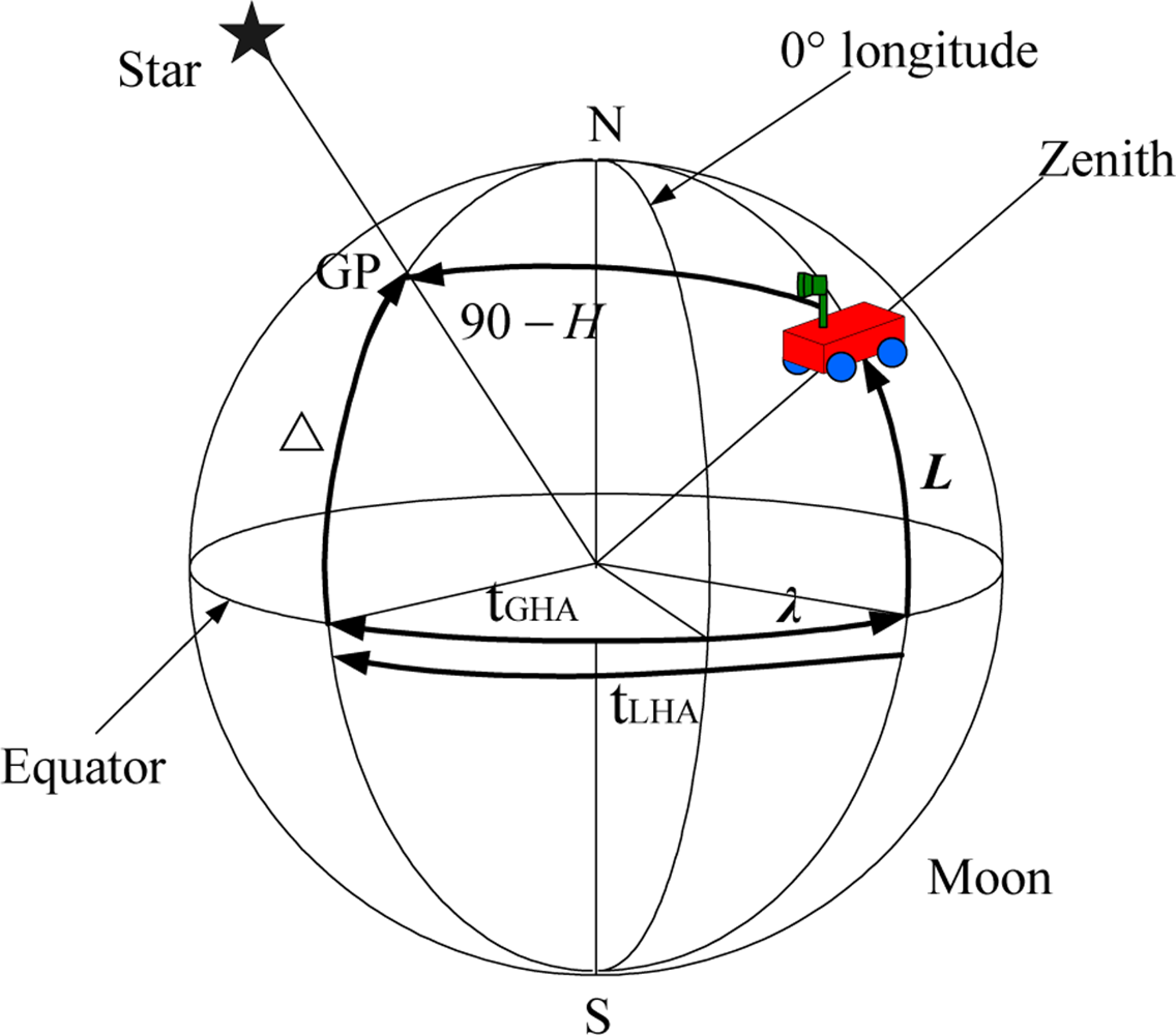
<list list-type="order">
<list-item>
<p>Star altitude. From <xref ref-type="disp-formula" rid="FD3">Equation (3)</xref>, the measurement equation of star height <italic>H</italic> is obtained as:
<disp-formula id="FD5">
<label>(5)</label>
<mml:math display="block">
<mml:mrow>
<mml:mtable>
<mml:mtr>
<mml:mtd>
<mml:mrow>
<mml:mi>H</mml:mi>
<mml:mo> </mml:mo>
<mml:mo>=</mml:mo>
<mml:mo> </mml:mo>
<mml:mtext>arcsin</mml:mtext>
<mml:mo stretchy="false">(</mml:mo>
<mml:mtext>sin</mml:mtext>
<mml:mo>ϕ</mml:mo>
<mml:mo> </mml:mo>
<mml:mo>⋅</mml:mo>
<mml:mo> </mml:mo>
<mml:mtext>sin</mml:mtext>
<mml:mo> </mml:mo>
<mml:mo>Δ</mml:mo>
<mml:mo> </mml:mo>
<mml:mo>+</mml:mo>
<mml:mo> </mml:mo>
<mml:mtext>cos</mml:mtext>
<mml:mo> </mml:mo>
<mml:mo>φ</mml:mo>
<mml:mo> </mml:mo>
<mml:mo>⋅</mml:mo>
<mml:mo> </mml:mo>
<mml:mtext>cos</mml:mtext>
<mml:mo> </mml:mo>
<mml:mo>Δ</mml:mo>
<mml:mo> </mml:mo>
<mml:mo>⋅</mml:mo>
<mml:mo> </mml:mo>
<mml:mtext>cos</mml:mtext>
<mml:mo> </mml:mo>
<mml:msub>
<mml:mrow>
<mml:mi>t</mml:mi></mml:mrow>
<mml:mrow>
<mml:mi mathvariant="italic">LHA</mml:mi></mml:mrow></mml:msub>
<mml:mo stretchy="false">)</mml:mo>
<mml:mo> </mml:mo>
<mml:mo>+</mml:mo>
<mml:mo> </mml:mo>
<mml:mo>α</mml:mo>
<mml:mo> </mml:mo>
<mml:mo>+</mml:mo>
<mml:mo> </mml:mo>
<mml:msub>
<mml:mrow>
<mml:mi>v</mml:mi></mml:mrow>
<mml:mi>H</mml:mi></mml:msub></mml:mrow></mml:mtd></mml:mtr>
<mml:mtr>
<mml:mtd>
<mml:mrow>
<mml:msub>
<mml:mrow>
<mml:mi>t</mml:mi></mml:mrow>
<mml:mrow>
<mml:mi mathvariant="italic">LHA</mml:mi></mml:mrow></mml:msub>
<mml:mo> </mml:mo>
<mml:mo>=</mml:mo>
<mml:mo> </mml:mo>
<mml:msub>
<mml:mrow>
<mml:mi>t</mml:mi></mml:mrow>
<mml:mrow>
<mml:mi mathvariant="italic">GHA</mml:mi></mml:mrow></mml:msub>
<mml:mo> </mml:mo>
<mml:mo>+</mml:mo>
<mml:mo> </mml:mo>
<mml:mo>λ</mml:mo></mml:mrow></mml:mtd></mml:mtr>
<mml:mtr>
<mml:mtd>
<mml:mrow>
<mml:mo>ϕ</mml:mo>
<mml:mo> </mml:mo>
<mml:mo>=</mml:mo>
<mml:mo> </mml:mo>
<mml:msub>
<mml:mrow>
<mml:mo>ϕ</mml:mo></mml:mrow>
<mml:mi>e</mml:mi></mml:msub>
<mml:mo> </mml:mo>
<mml:mo>+</mml:mo>
<mml:mo> </mml:mo>
<mml:mo>Δ</mml:mo>
<mml:mo>ϕ</mml:mo></mml:mrow></mml:mtd></mml:mtr>
<mml:mtr>
<mml:mtd>
<mml:mrow>
<mml:mo>λ</mml:mo>
<mml:mo> </mml:mo>
<mml:mo>=</mml:mo>
<mml:mo> </mml:mo>
<mml:msub>
<mml:mrow>
<mml:mo>λ</mml:mo></mml:mrow>
<mml:mi>e</mml:mi></mml:msub>
<mml:mo> </mml:mo>
<mml:mo>+</mml:mo>
<mml:mo> </mml:mo>
<mml:mo>Δ</mml:mo>
<mml:mo>λ</mml:mo></mml:mrow></mml:mtd></mml:mtr></mml:mtable></mml:mrow></mml:math></disp-formula>where <italic>λ<sub>e</sub></italic>, <italic>ϕ<sub>e</sub></italic> are the pre-estimated longitude and latitude of lunar probe respectively, which is provided by ground tracking network. The error between <italic>λ<sub>e</sub></italic>, <italic>ϕ<sub>e</sub></italic> and the true value is about 1,000 m. <italic>α</italic> is the systematic error in the star altitude measurement as mentioned above and <italic>v<sub>H</sub></italic> is measurement noise.</p></list-item>
<list-item>
<p>Star direction vector. The observation information measured by star sensor also provides an indication of the lunar explorer’s attitude information. Given the 2-D star centroid from the threshold star image, a 3-D star-direction unit vector <italic>s<sub>b</sub></italic> = [<italic>x<sub>b</sub></italic>,<italic>y<sub>b</sub></italic>,<italic>z<sub>b</sub></italic>]<italic><sup>T</sup></italic> in the explorer body frame can be computed [<xref ref-type="bibr" rid="b21-sensors-11-06991">21</xref>]. At the same time, the vector direction of star in the Moon fixed frame can be obtained from the Astronomical Almanac, given as follows: <italic>s<sub>m</sub></italic> = [<italic>x<sub>m</sub></italic>,<italic>y<sub>m</sub></italic>,<italic>z<sub>m</sub></italic>]<italic><sup>T</sup></italic> = [cosΔcos <italic>t<sub>LHA</sub></italic>, cosΔsin <italic>t<sub>LHA</sub></italic>, sinΔ]<italic><sup>T</sup></italic> The relation between <italic>s<sub>b</sub></italic> and <italic>s<sub>m</sub></italic> is:
<disp-formula id="FD6">
<label>(6)</label>
<mml:math display="block">
<mml:mrow>
<mml:msub>
<mml:mrow>
<mml:mi>s</mml:mi></mml:mrow>
<mml:mi>m</mml:mi></mml:msub>
<mml:mo> </mml:mo>
<mml:mo>=</mml:mo>
<mml:mo> </mml:mo>
<mml:msubsup>
<mml:mrow>
<mml:mi>R</mml:mi></mml:mrow>
<mml:mi>n</mml:mi>
<mml:mi>m</mml:mi></mml:msubsup>
<mml:mo> </mml:mo>
<mml:mo>⋅</mml:mo>
<mml:mo> </mml:mo>
<mml:msubsup>
<mml:mrow>
<mml:mi>R</mml:mi></mml:mrow>
<mml:mi>b</mml:mi>
<mml:mi>n</mml:mi></mml:msubsup>
<mml:mo> </mml:mo>
<mml:mo>⋅</mml:mo>
<mml:mo> </mml:mo>
<mml:msub>
<mml:mrow>
<mml:mi>s</mml:mi></mml:mrow>
<mml:mi>b</mml:mi></mml:msub></mml:mrow></mml:math></disp-formula>where 
<inline-formula>
<mml:math>
<mml:mrow>
<mml:msubsup>
<mml:mrow>
<mml:mi>R</mml:mi></mml:mrow>
<mml:mi>n</mml:mi>
<mml:mi>m</mml:mi></mml:msubsup></mml:mrow></mml:math></inline-formula> is the transformation matrix from the navigation frame to the Moon fixed frame:
<disp-formula id="FD7">
<label>(7)</label>
<mml:math display="block">
<mml:mrow>
<mml:msubsup>
<mml:mrow>
<mml:mi>R</mml:mi></mml:mrow>
<mml:mi>n</mml:mi>
<mml:mi>m</mml:mi></mml:msubsup>
<mml:mo> </mml:mo>
<mml:mo>=</mml:mo>
<mml:mo> </mml:mo>
<mml:mrow>
<mml:mo>[</mml:mo>
<mml:mrow>
<mml:mtable>
<mml:mtr>
<mml:mtd>
<mml:mrow>
<mml:mo>−</mml:mo>
<mml:mtext>sin</mml:mtext>
<mml:mo> </mml:mo>
<mml:mo>λ</mml:mo></mml:mrow></mml:mtd>
<mml:mtd>
<mml:mrow>
<mml:mo>−</mml:mo>
<mml:mtext>sin</mml:mtext>
<mml:mo> </mml:mo>
<mml:mi>L</mml:mi>
<mml:mo> </mml:mo>
<mml:mtext>cos</mml:mtext>
<mml:mo> </mml:mo>
<mml:mo>λ</mml:mo></mml:mrow></mml:mtd>
<mml:mtd>
<mml:mrow>
<mml:mtext>cos</mml:mtext>
<mml:mo> </mml:mo>
<mml:mi>L</mml:mi>
<mml:mo> </mml:mo>
<mml:mtext>cos</mml:mtext>
<mml:mo> </mml:mo>
<mml:mo>λ</mml:mo></mml:mrow></mml:mtd></mml:mtr>
<mml:mtr>
<mml:mtd>
<mml:mrow>
<mml:mtext>cos</mml:mtext>
<mml:mo> </mml:mo>
<mml:mo>λ</mml:mo></mml:mrow></mml:mtd>
<mml:mtd>
<mml:mrow>
<mml:mo>−</mml:mo>
<mml:mtext>sin</mml:mtext>
<mml:mo> </mml:mo>
<mml:mi>L</mml:mi>
<mml:mo> </mml:mo>
<mml:mtext>sin</mml:mtext>
<mml:mo> </mml:mo>
<mml:mo>λ</mml:mo></mml:mrow></mml:mtd>
<mml:mtd>
<mml:mrow>
<mml:mtext>cos</mml:mtext>
<mml:mo> </mml:mo>
<mml:mi>L</mml:mi>
<mml:mo> </mml:mo>
<mml:mtext>sin</mml:mtext>
<mml:mo> </mml:mo>
<mml:mo>λ</mml:mo></mml:mrow></mml:mtd></mml:mtr>
<mml:mtr>
<mml:mtd>
<mml:mn>0</mml:mn></mml:mtd>
<mml:mtd>
<mml:mrow>
<mml:mtext>cos</mml:mtext>
<mml:mo> </mml:mo>
<mml:mi>L</mml:mi></mml:mrow></mml:mtd>
<mml:mtd>
<mml:mrow>
<mml:mtext>sin</mml:mtext>
<mml:mo> </mml:mo>
<mml:mi>L</mml:mi></mml:mrow></mml:mtd></mml:mtr></mml:mtable></mml:mrow>
<mml:mo>]</mml:mo></mml:mrow></mml:mrow></mml:math></disp-formula></p></list-item>
<list-item>
<p>Output of accelerometers:
<disp-formula id="FD8">
<label>(8)</label>
<mml:math display="block">
<mml:mrow>
<mml:mtable>
<mml:mtr>
<mml:mtd>
<mml:mrow>
<mml:msup>
<mml:mrow>
<mml:mi>f</mml:mi></mml:mrow>
<mml:mi>b</mml:mi></mml:msup>
<mml:mo> </mml:mo>
<mml:mo>=</mml:mo>
<mml:mo> </mml:mo>
<mml:msubsup>
<mml:mrow>
<mml:mi>R</mml:mi></mml:mrow>
<mml:mi>n</mml:mi>
<mml:mi>b</mml:mi></mml:msubsup>
<mml:mo> </mml:mo>
<mml:mo>⋅</mml:mo>
<mml:mo> </mml:mo>
<mml:msub>
<mml:mrow>
<mml:mi>g</mml:mi></mml:mrow>
<mml:mi>t</mml:mi></mml:msub>
<mml:mo> </mml:mo>
<mml:mo>+</mml:mo>
<mml:mo> </mml:mo>
<mml:msub>
<mml:mrow>
<mml:mi>g</mml:mi></mml:mrow>
<mml:mo>Δ</mml:mo></mml:msub></mml:mrow></mml:mtd></mml:mtr>
<mml:mtr>
<mml:mtd>
<mml:mrow>
<mml:msub>
<mml:mrow>
<mml:mi>g</mml:mi></mml:mrow>
<mml:mi>t</mml:mi></mml:msub>
<mml:mo> </mml:mo>
<mml:mo>=</mml:mo>
<mml:mo> </mml:mo>
<mml:msup>
<mml:mrow>
<mml:mrow>
<mml:mo stretchy="false">[</mml:mo>
<mml:mn>0</mml:mn>
<mml:mo>,</mml:mo>
<mml:mn>0</mml:mn>
<mml:mo>,</mml:mo>
<mml:mn>1.618</mml:mn>
<mml:mo stretchy="false">]</mml:mo></mml:mrow></mml:mrow>
<mml:mi>T</mml:mi></mml:msup></mml:mrow></mml:mtd></mml:mtr>
<mml:mtr>
<mml:mtd>
<mml:mrow>
<mml:msub>
<mml:mrow>
<mml:mi>g</mml:mi></mml:mrow>
<mml:mo>Δ</mml:mo></mml:msub>
<mml:mo> </mml:mo>
<mml:mo>=</mml:mo>
<mml:mo> </mml:mo>
<mml:msup>
<mml:mrow>
<mml:mrow>
<mml:mo stretchy="false">[</mml:mo>
<mml:msub>
<mml:mrow>
<mml:mi>a</mml:mi></mml:mrow>
<mml:mi>x</mml:mi></mml:msub>
<mml:mo>,</mml:mo>
<mml:mo> </mml:mo>
<mml:msub>
<mml:mrow>
<mml:mi>a</mml:mi></mml:mrow>
<mml:mi>y</mml:mi></mml:msub>
<mml:mo>,</mml:mo>
<mml:mo> </mml:mo>
<mml:msub>
<mml:mrow>
<mml:mi>a</mml:mi></mml:mrow>
<mml:mi>z</mml:mi></mml:msub>
<mml:mo stretchy="false">]</mml:mo></mml:mrow></mml:mrow>
<mml:mi>T</mml:mi></mml:msup></mml:mrow></mml:mtd></mml:mtr></mml:mtable></mml:mrow></mml:math></disp-formula>where <italic>f<sup>b</sup></italic> is the output of accelerometers, <italic>g<sub>t</sub></italic> is gravity vector, <italic>g</italic><sub>Δ</sub> is the vector of accelerometers biases.</p></list-item>
<list-item>
<p>Output of gyros:
<disp-formula id="FD9">
<label>(9)</label>
<mml:math display="block">
<mml:mrow>
<mml:mtable>
<mml:mtr>
<mml:mtd>
<mml:mrow>
<mml:msup>
<mml:mrow>
<mml:mi>w</mml:mi></mml:mrow>
<mml:mi>b</mml:mi></mml:msup>
<mml:mo> </mml:mo>
<mml:mo>=</mml:mo>
<mml:mo> </mml:mo>
<mml:msubsup>
<mml:mrow>
<mml:mi>R</mml:mi></mml:mrow>
<mml:mi>n</mml:mi>
<mml:mi>b</mml:mi></mml:msubsup>
<mml:mo> </mml:mo>
<mml:mo>⋅</mml:mo>
<mml:mo> </mml:mo>
<mml:msubsup>
<mml:mrow>
<mml:mi>R</mml:mi></mml:mrow>
<mml:mi>m</mml:mi>
<mml:mi>n</mml:mi></mml:msubsup>
<mml:mo> </mml:mo>
<mml:mo>⋅</mml:mo>
<mml:mo> </mml:mo>
<mml:msub>
<mml:mrow>
<mml:mi>w</mml:mi></mml:mrow>
<mml:mi>t</mml:mi></mml:msub>
<mml:mo> </mml:mo>
<mml:mo>+</mml:mo>
<mml:mo> </mml:mo>
<mml:msub>
<mml:mrow>
<mml:mi>w</mml:mi></mml:mrow>
<mml:mo>Δ</mml:mo></mml:msub></mml:mrow></mml:mtd></mml:mtr>
<mml:mtr>
<mml:mtd>
<mml:mrow>
<mml:msub>
<mml:mrow>
<mml:mi>w</mml:mi></mml:mrow>
<mml:mi>t</mml:mi></mml:msub>
<mml:mo> </mml:mo>
<mml:mo>=</mml:mo>
<mml:mo> </mml:mo>
<mml:msup>
<mml:mrow>
<mml:mrow>
<mml:mo stretchy="false">[</mml:mo>
<mml:mn>0</mml:mn>
<mml:mo>,</mml:mo>
<mml:mo> </mml:mo>
<mml:mn>0</mml:mn>
<mml:mo>,</mml:mo>
<mml:mo> </mml:mo>
<mml:mn>2.6617</mml:mn>
<mml:mi>e</mml:mi>
<mml:mo>−</mml:mo>
<mml:mn>6</mml:mn>
<mml:mo stretchy="false">]</mml:mo></mml:mrow></mml:mrow>
<mml:mi>T</mml:mi></mml:msup></mml:mrow></mml:mtd></mml:mtr>
<mml:mtr>
<mml:mtd>
<mml:mrow>
<mml:msub>
<mml:mrow>
<mml:mi>w</mml:mi></mml:mrow>
<mml:mo>Δ</mml:mo></mml:msub>
<mml:mo> </mml:mo>
<mml:mo>=</mml:mo>
<mml:mo> </mml:mo>
<mml:msup>
<mml:mrow>
<mml:mrow>
<mml:mo stretchy="false">[</mml:mo>
<mml:msub>
<mml:mrow>
<mml:mi>b</mml:mi></mml:mrow>
<mml:mi>x</mml:mi></mml:msub>
<mml:mo>,</mml:mo>
<mml:mo> </mml:mo>
<mml:msub>
<mml:mrow>
<mml:mi>b</mml:mi></mml:mrow>
<mml:mi>y</mml:mi></mml:msub>
<mml:mo>,</mml:mo>
<mml:mo> </mml:mo>
<mml:msub>
<mml:mrow>
<mml:mi>b</mml:mi></mml:mrow>
<mml:mi>z</mml:mi></mml:msub>
<mml:mo stretchy="false">]</mml:mo></mml:mrow></mml:mrow>
<mml:mi>T</mml:mi></mml:msup></mml:mrow></mml:mtd></mml:mtr></mml:mtable></mml:mrow></mml:math></disp-formula>where <italic>w<sup>b</sup></italic> is the output of gyros, <italic>w<sub>t</sub></italic> is the lunar rotation rate, <italic>w</italic><sub>Δ</sub> is the vector of gyros biases. Using <xref ref-type="disp-formula" rid="FD5">Equations (5</xref>–<xref ref-type="disp-formula" rid="FD9">9)</xref>, we can obtain the following measurement model of this celestial assisted INS initialization method:
<disp-formula id="FD10">
<label>(10)</label>
<mml:math display="block">
<mml:mrow>
<mml:mi>Z</mml:mi>
<mml:mo> </mml:mo>
<mml:mo>=</mml:mo>
<mml:mo> </mml:mo>
<mml:mo stretchy="false">[</mml:mo>
<mml:mi>H</mml:mi>
<mml:mo>,</mml:mo>
<mml:mo> </mml:mo>
<mml:msub>
<mml:mrow>
<mml:mi>s</mml:mi></mml:mrow>
<mml:mi>b</mml:mi></mml:msub>
<mml:mo>,</mml:mo>
<mml:mo> </mml:mo>
<mml:msup>
<mml:mrow>
<mml:mi>f</mml:mi></mml:mrow>
<mml:mi>b</mml:mi></mml:msup>
<mml:mo>,</mml:mo>
<mml:mo> </mml:mo>
<mml:msup>
<mml:mrow>
<mml:mi>w</mml:mi></mml:mrow>
<mml:mi>b</mml:mi></mml:msup>
<mml:mo stretchy="false">]</mml:mo></mml:mrow></mml:math></disp-formula></p></list-item></list></p></sec>
<sec>
<label>3.3.</label>
<title>UKF Method</title>
<p>
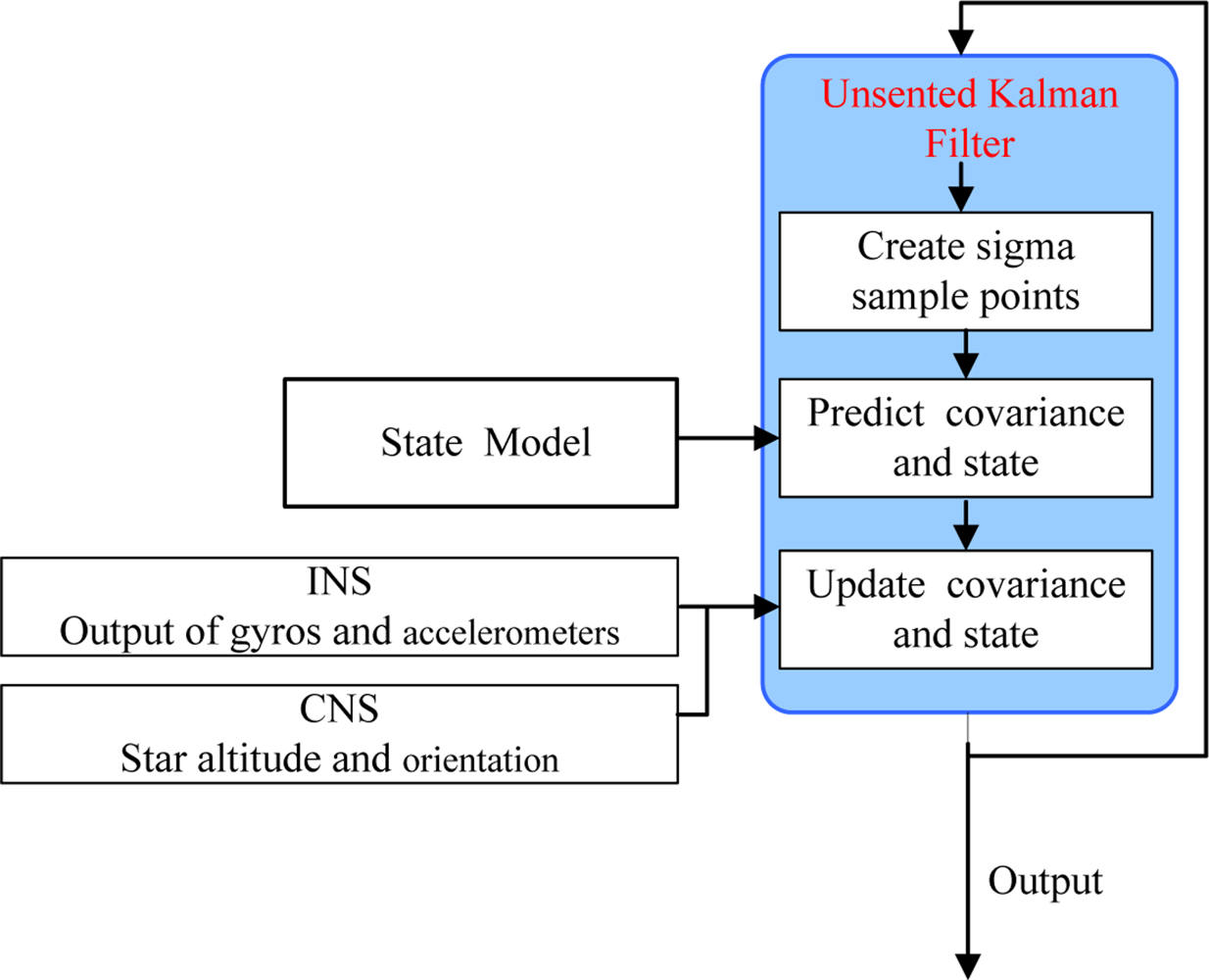
The Kalman filter (KF), which is optimal for application to linear and Gaussian systems, is often used in the INS initialization [<xref ref-type="bibr" rid="b22-sensors-11-06991">22</xref>]. However, in this celestial assisted INS initialization system, the measurement model is nonlinear. Since UKF has lower estimation errors than the Extended Kalman filter (EKF) for nonlinear systems and it also avoids the derivation of Jacobian matrices, UKF is used in this study [<xref ref-type="bibr" rid="b23-sensors-11-06991">23</xref>,<xref ref-type="bibr" rid="b24-sensors-11-06991">24</xref>]. The block diagram of the celestial assisted INS initialization method based on UKF is shown in <xref ref-type="fig" rid="f3-sensors-11-06991">Figure 3</xref>.</p></sec></sec>
<sec sec-type="results|discussion">
<label>4.</label>
<title>Results and Discussion</title>
<p>
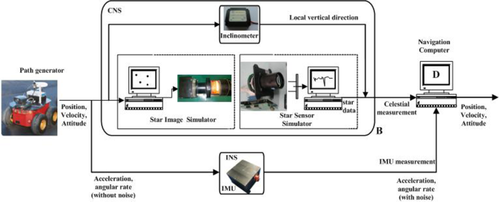
This section presents simulations of this celestial assisted INS initialization method. All simulation data comes from the lunar explorer INS/CNS simulation system shown in <xref ref-type="fig" rid="f4-sensors-11-06991">Figure 4</xref>. This system is composed of a lunar explorer simulator, a real-world model characterizing both navigation environment and on-board sensors and a navigation computer. A pioneer-3A robot is used as the lunar explorer simulator to evaluate navigation performance. The INS is composed of an IMU, which is composed of three optical fiber gyroscopes and three quartz pendulum accelerometers. The IMU is rigidly mounted parallel to the body axes of the explorer. The bias of each gyroscope is 0.05°/h and the bias of each accelerometer is 10 μg. The update rates of both sensors are 100 Hz. The CNS consists of a star image simulator, a star sensor and an inclinometer. The star image simulator is used to produce the simulation star image according to the explorer’s position, attitude, the Astronomical Almanac and astronomy software, <italic>etc.</italic> The accuracy of star sensor is 3″ (1σ) and its update rate is 5 Hz. The inclinometer used is a NS–45/P2 dual-axis inclinometer. The precision of the inclinometer is 0.03° and its update rate is 20 Hz.</p>
<p>
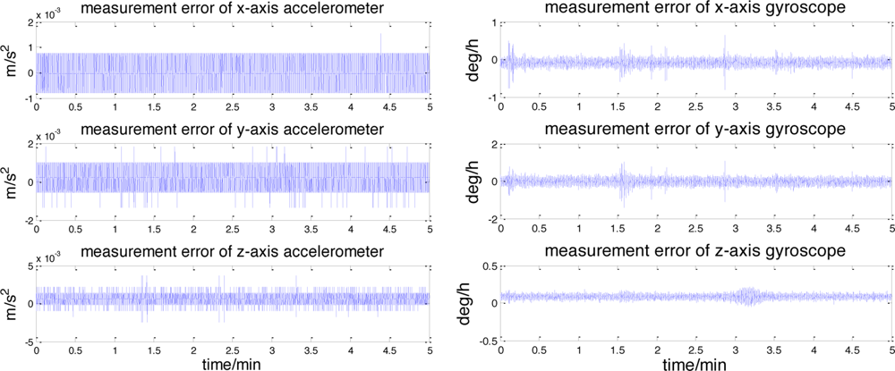
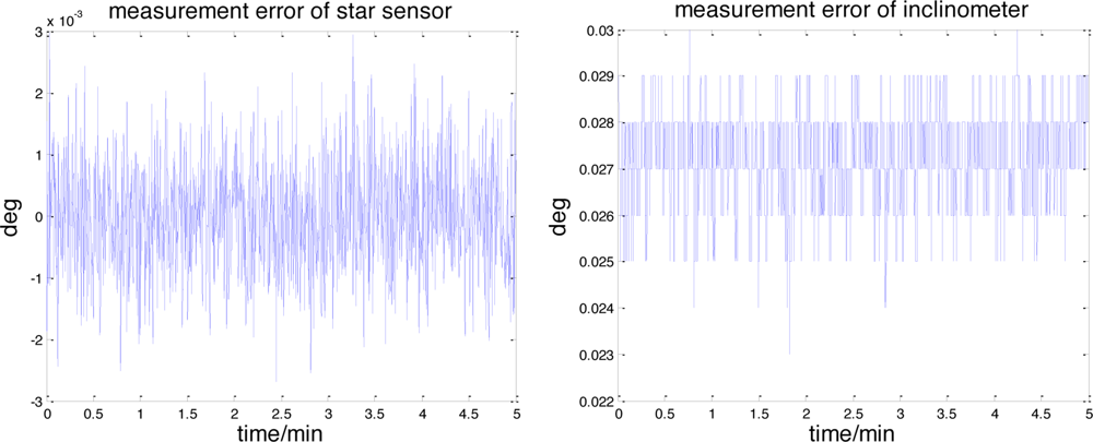
In simulations, measurement errors are separated from the real data and used to create simulation measurements on the lunar surface. The error characteristics of the accelerometers and gyroscopes are shown in <xref ref-type="fig" rid="f5-sensors-11-06991">Figure 5</xref>. It can be seen that each accelerometer measurement error consists of a constant bias and the random noise, which can also be observed in the gyroscopes. The raw measurement errors of the star sensor and the inclinometer are depicted in <xref ref-type="fig" rid="f6-sensors-11-06991">Figure 6</xref>.</p>
<p>Similar to <xref ref-type="fig" rid="f5-sensors-11-06991">Figure 5</xref>, the dominant components of these errors also consists of the constant bias and the random noise. The landsite of USA Surveyor III (2°56′N, 336°40′E) is chosen as the initial position. The lunar rover stays still, its initial yaw, roll and pitch angles are 20°, 0° and 0°. The entire simulation time is 5 min.
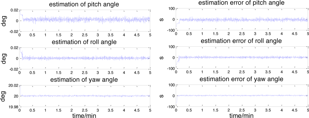
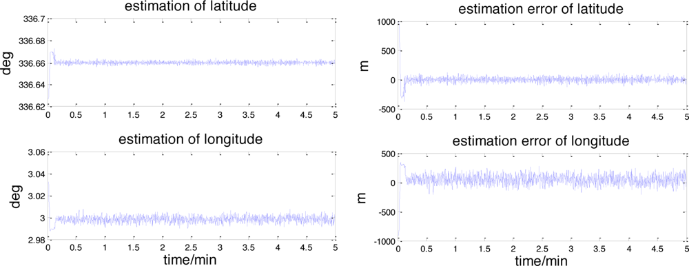
</p>
<p><xref ref-type="fig" rid="f7-sensors-11-06991">Figure 7</xref> and <xref ref-type="fig" rid="f8-sensors-11-06991">Figure 8</xref> shows the results of this celestial assisted INS initialization method. As indicated in these figures, the UKF filter converges rapidly within 10 seconds from the start of the run. After the filter convergence period, the estimated values of latitude and longitude converge to 336.66° and 2.9984° quickly, which are very close to the true value 336.6585° and 3.0023°. The root mean square (RMS) estimation errors of latitude and longitude are 39.9239 m and 90.4737 m. The maximum estimation errors of latitude and longitude are 131.8504 m and 276.1276 m.</p>
<p>The estimated attitude also converges to the real attitude quickly. The root mean square (RMS) attitude errors are 11.3343″, 5.9231″ and 2.8087″ respectively in yaw, roll and pitch angle. The maximum estimation errors of these angles are 36.3830″, 19.7239″ and 10.2493″. From these results, it can be concluded that this celestial assisted INS initialization method can enhance the position and attitude estimation accuracy. The maximum error in position is 300 m and in attitude 40″, which is much better than that sent by ground stations.
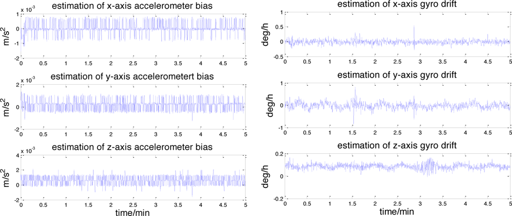
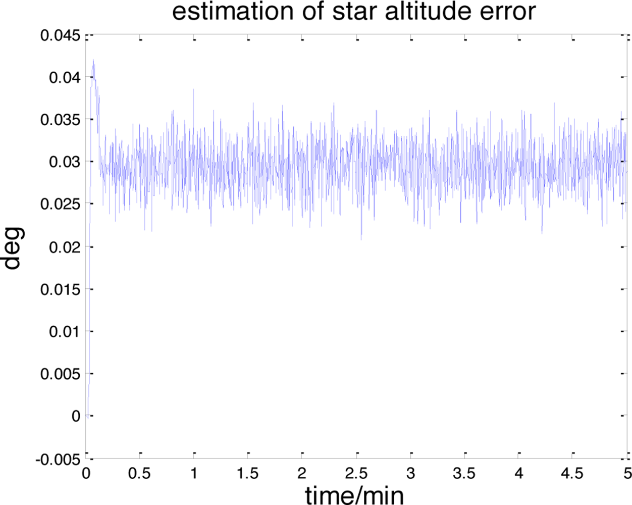
</p>
<p><xref ref-type="fig" rid="f9-sensors-11-06991">Figure 9</xref> illustrates the accelerometer and gyroscope errors estimated by this celestial assisted INS initialization method. These results are coherent with the true measurement errors, as evidenced in <xref ref-type="fig" rid="f5-sensors-11-06991">Figure 5</xref>. The systematic error estimation result of star altitude in the CNS is presented in <xref ref-type="fig" rid="f10-sensors-11-06991">Figure 10</xref>. Compared with <xref ref-type="fig" rid="f6-sensors-11-06991">Figure 6</xref>, we can see that the estimation is consistent with the measurement error caused by the star sensor and the inclinometer. From these figures, it is clear that the celestial assisted INS initialization method developed in this paper is able to accurately estimate the accelerometer and gyroscope errors. Furthermore, it is also can estimate the systematic error in the CNS effectively.</p></sec>
<sec sec-type="conclusions">
<label>5.</label>
<title>Conclusions</title>
<p>In this study, a new celestial assisted INS initialization method for lunar explorers, which could solve the INS initialization and CNS calibration problems at the same time, is presented. To make the state model simple and observable, position, attitude, and main error resources are used as state variables. All original information provided by the sensors of the INS and the CNS is used as measurements. An unscented Kalman filter is used to deal with these measurements and estimate the states. The method is tested using a ground simulation system. The estimation error of initial position is within 300 m and the estimation error of initial attitude is within 40″. Both the inertial sensors’ biases in the INS and the systematic error in the CNS are estimated effectively. Results allow the conclusion that this celestial assisted INS initialization method is a promising method for the high accuracy initialization of a lunar explorer. It should be noted that the proposed approach is general and may be used on any kind of lunar explorers on the lunar surface, such as lunar rovers, landers and ascenders, with an equivalent set of sensors. Future directions of research include applications (extensions) of this method to cases where the INS and CNS are fused with other navigation sensors (e.g., vision sensors, beacons <italic>etc.</italic>)</p></sec></body>
<back>
<ack>
<p>The work described in this paper was supported by National Natural Science Foundation of China (60874095) and Hi-tech Research and Development Program of China. The author would like to thank all members of the Inertial Technology Key Laboratory, for their useful comments regarding this work effort.</p></ack>
<ref-list>
<title>References</title>
<ref id="b1-sensors-11-06991"><label>1.</label><citation citation-type="book"><person-group person-group-type="author"><name><surname>Grewal</surname><given-names>MS</given-names></name><name><surname>Weill</surname><given-names>LR</given-names></name><name><surname>Angus</surname><given-names>PA</given-names></name></person-group><source>Global Positioning Systems, Inertial Navigation, and Integration</source><edition>2nd Ed</edition><publisher-name>John Wiley &amp; Sons</publisher-name><publisher-loc>Hoboken, NJ, USA</publisher-loc><year>2007</year></citation></ref>
<ref id="b2-sensors-11-06991"><label>2.</label><citation citation-type="book"><person-group person-group-type="author"><name><surname>Jekeli</surname><given-names>C</given-names></name></person-group><source>Inertial Navigation Systems with Geodetic Application</source><publisher-name>Walter de Gruyter</publisher-name><publisher-loc>Berlin, Germany</publisher-loc><year>2000</year></citation></ref>
<ref id="b3-sensors-11-06991"><label>3.</label><citation citation-type="journal"><person-group person-group-type="author"><name><surname>Ning</surname><given-names>XL</given-names></name><name><surname>Fang</surname><given-names>JC</given-names></name></person-group><article-title>A new autonomous celestial navigation method for the lunar rover</article-title><source>Rob. Autonomous Syst</source><year>2009</year><volume>57</volume><fpage>48</fpage><lpage>54</lpage><pub-id pub-id-type="doi">10.1016/j.robot.2008.02.006</pub-id></citation></ref>
<ref id="b4-sensors-11-06991"><label>4.</label><citation citation-type="journal"><person-group person-group-type="author"><name><surname>Goldstein</surname><given-names>MS</given-names></name><name><surname>Greenwood</surname><given-names>IA</given-names></name><name><surname>Kuritsky</surname><given-names>MM</given-names></name><name><surname>Lerman</surname><given-names>H</given-names></name><name><surname>McCarthy</surname><given-names>JE</given-names></name><name><surname>Shanahan</surname><given-names>T</given-names></name><name><surname>Silver</surname><given-names>M</given-names></name><name><surname>Simpson</surname><given-names>JH</given-names></name></person-group><article-title>Inertial navigation</article-title><source>Proc. IEEE</source><year>1983</year><volume>71</volume><fpage>1156</fpage><lpage>1176</lpage><pub-id pub-id-type="doi">10.1109/PROC.1983.12744</pub-id></citation></ref>
<ref id="b5-sensors-11-06991"><label>5.</label><citation citation-type="book"><person-group person-group-type="author"><name><surname>Rogers</surname><given-names>RM</given-names></name></person-group><source>Applied Mathematics in Integrated Navigation Systems</source><edition>3rd Ed</edition><publisher-name>AIAA</publisher-name><publisher-loc>Reston, VA, USA</publisher-loc><year>2007</year></citation></ref>
<ref id="b6-sensors-11-06991"><label>6.</label><citation citation-type="book"><person-group person-group-type="author"><name><surname>Shin</surname><given-names>E-H</given-names></name></person-group><article-title>Accuracy Improvement of Low Cost INS/GPS for Land Application</article-title><publisher-name>University of Calgary</publisher-name><publisher-loc>Calgary, AB, Canada</publisher-loc><year>2001</year></citation></ref>
<ref id="b7-sensors-11-06991"><label>7.</label><citation citation-type="journal"><person-group person-group-type="author"><name><surname>Bar-Itzhack</surname><given-names>IY</given-names></name><name><surname>Goshen-Meskin</surname><given-names>D</given-names></name></person-group><article-title>Identity between INS position and velocity error equations in the true frame</article-title><source>J. Guidance Control Dyn</source><year>1988</year><volume>6</volume><fpage>590</fpage><lpage>592</lpage></citation></ref>
<ref id="b8-sensors-11-06991"><label>8.</label><citation citation-type="confproc"><person-group person-group-type="author"><name><surname>Rogers</surname><given-names>RM</given-names></name></person-group><article-title>Comparison of Inertial Navigation System Error Models in Application to IMU Transfer Alignment</article-title><conf-name>Proceedings of the AIAA Guidance, Navigation and Control Conference</conf-name><conf-loc>New Orleans, IA, USA</conf-loc><conf-date>11–13 August 1997</conf-date><fpage>686</fpage><lpage>695</lpage></citation></ref>
<ref id="b9-sensors-11-06991"><label>9.</label><citation citation-type="journal"><person-group person-group-type="author"><name><surname>Chung</surname><given-names>DY</given-names></name><name><surname>Lee</surname><given-names>JG</given-names></name><name><surname>Park</surname><given-names>CG</given-names></name><name><surname>Park</surname><given-names>HW</given-names></name></person-group><article-title>Strapdown INS error model for multiposition alignment</article-title><source>IEEE Trans. Aerosp. Electron. Syst</source><year>1996</year><volume>4</volume><fpage>1362</fpage><lpage>1366</lpage></citation></ref>
<ref id="b10-sensors-11-06991"><label>10.</label><citation citation-type="journal"><person-group person-group-type="author"><name><surname>Dmitriyev</surname><given-names>SP</given-names></name><name><surname>Stepanov</surname><given-names>OA</given-names></name><name><surname>Shepel</surname><given-names>SV</given-names></name></person-group><article-title>Nonlinear filtering methods application in INS alignment</article-title><source>IEEE Trans. Aerosp. Electron. Syst</source><year>1997</year><volume>1</volume><fpage>260</fpage><lpage>271</lpage></citation></ref>
<ref id="b11-sensors-11-06991"><label>11.</label><citation citation-type="journal"><person-group person-group-type="author"><name><surname>Shaolin</surname><given-names>L</given-names></name><name><surname>Ling</surname><given-names>X</given-names></name><name><surname>Jiabin</surname><given-names>C</given-names></name></person-group><article-title>New techniques for initial alignment of strapdown inertial navigation system</article-title><source>J. Franklin Inst</source><year>2009</year><volume>10</volume><fpage>1021</fpage><lpage>1037</lpage></citation></ref>
<ref id="b12-sensors-11-06991"><label>12.</label><citation citation-type="journal"><person-group person-group-type="author"><name><surname>Goshen-Meskin</surname><given-names>D</given-names></name><name><surname>Bar-Itzhack</surname><given-names>IY</given-names></name></person-group><article-title>Observability analysis of piece-wise constant system, Part II: Application to inertial navigation in-flight alignment</article-title><source>IEEE Trans. Aerosp. Electron. Syst</source><year>1992</year><volume>4</volume><fpage>1068</fpage><lpage>1075</lpage></citation></ref>
<ref id="b13-sensors-11-06991"><label>13.</label><citation citation-type="journal"><person-group person-group-type="author"><name><surname>Batista</surname><given-names>P</given-names></name><name><surname>Silvestre</surname><given-names>C</given-names></name><name><surname>Oliveira</surname><given-names>P</given-names></name></person-group><article-title>On the observability of linear motion quantities in navigation systems</article-title><source>Syst. Control Lett</source><year>2011</year><volume>2</volume><fpage>101</fpage><lpage>110</lpage></citation></ref>
<ref id="b14-sensors-11-06991"><label>14.</label><citation citation-type="journal"><person-group person-group-type="author"><name><surname>Fang</surname><given-names>JC</given-names></name><name><surname>Wang</surname><given-names>DJ</given-names></name></person-group><article-title>A fast initial alignment method for strapdown inertial navigation system on stationary base</article-title><source>IEEE Trans. Aerosp. Electron. Syst</source><year>1996</year><volume>32</volume><fpage>1501</fpage><lpage>1504</lpage><pub-id pub-id-type="doi">10.1109/7.543871</pub-id></citation></ref>
<ref id="b15-sensors-11-06991"><label>15.</label><citation citation-type="journal"><person-group person-group-type="author"><name><surname>Zhang</surname><given-names>CB</given-names></name><name><surname>Tian</surname><given-names>WF</given-names></name><name><surname>Jin</surname><given-names>ZH</given-names></name></person-group><article-title>A novel method improving the alignment accuracy of a strapdown inertial navigation system on a stationary base</article-title><source>Meas. Sci. Technol</source><year>2004</year><volume>15</volume><fpage>765</fpage><lpage>769</lpage><pub-id pub-id-type="doi">10.1088/0957-0233/15/4/021</pub-id></citation></ref>
<ref id="b16-sensors-11-06991"><label>16.</label><citation citation-type="confproc"><person-group person-group-type="author"><name><surname>Trautner</surname><given-names>R</given-names></name><name><surname>Bello Mora</surname><given-names>M</given-names></name><name><surname>Hechler</surname><given-names>M</given-names></name><name><surname>Koschny</surname><given-names>D</given-names></name></person-group><article-title>A New Celestial Navigation Method for Mars Landers</article-title><conf-name>Proceedings of the 35th Lunar and Planetary Science Conference</conf-name><conf-loc>League City, TX, USA</conf-loc><conf-date>15–19 March 2004</conf-date></citation></ref>
<ref id="b17-sensors-11-06991"><label>17.</label><citation citation-type="confproc"><person-group person-group-type="author"><name><surname>Thein</surname><given-names>ML</given-names></name></person-group><article-title>Celestial Navigation (CelNav): Lunar Surface Navigation</article-title><conf-name>Proceedings of the 2008 AIAA/AAS Astrodynamics Specialist Congress and Exposition</conf-name><conf-loc>Honolulu, HI, USA</conf-loc><conf-date>August 2008</conf-date><fpage>1</fpage><lpage>19</lpage></citation></ref>
<ref id="b18-sensors-11-06991"><label>18.</label><citation citation-type="journal"><person-group person-group-type="author"><name><surname>Lee</surname><given-names>H</given-names></name></person-group><article-title>An integration of GPS with INS sensors for precise long-baseline kinematic positioning</article-title><source>Sensors</source><year>2010</year><volume>10</volume><fpage>9424</fpage><lpage>9438</lpage><pub-id pub-id-type="doi">10.3390/s101009424</pub-id><pub-id pub-id-type="pmid">22163417</pub-id></citation></ref>
<ref id="b19-sensors-11-06991"><label>19.</label><citation citation-type="confproc"><person-group person-group-type="author"><name><surname>Acharya</surname><given-names>A</given-names></name><name><surname>Sadhu</surname><given-names>S</given-names></name><name><surname>Ghoshal</surname><given-names>TK</given-names></name></person-group><article-title>Improving Self-Alignment of Strapdown INS Using Measurement Augmentation</article-title><conf-name>Proceedings of the 12th International Conference on Information Fusion</conf-name><conf-loc>Seattle, WA, USA</conf-loc><conf-date>6–9 July 2009</conf-date></citation></ref>
<ref id="b20-sensors-11-06991"><label>20.</label><citation citation-type="confproc"><person-group person-group-type="author"><name><surname>Samer</surname><given-names>SS</given-names></name><name><surname>Kristjan</surname><given-names>TG</given-names></name></person-group><article-title>Automatic Alignment and Calibration of an Inertial Navigation System</article-title><conf-name>Proceedings of the IEEE Position Location and Navigation Symposium (PLANS)</conf-name><conf-loc>Las Vegas, NV, USA</conf-loc><conf-date>11–15 April 1994</conf-date><fpage>845</fpage><lpage>852</lpage></citation></ref>
<ref id="b21-sensors-11-06991"><label>21.</label><citation citation-type="confproc"><person-group person-group-type="author"><name><surname>Veth</surname><given-names>M</given-names></name><name><surname>Raquet</surname><given-names>J</given-names></name></person-group><article-title>Alignment and Calibration of Optical and Inertial Sensors Using Stellar Observations</article-title><conf-name>Proceedings of the 18th International Technical Meeting of the Satellite Division of the Institute of Navigation (ION GNSS 2005)</conf-name><conf-loc>Long Beach, CA, USA</conf-loc><conf-date>September 2005</conf-date></citation></ref>
<ref id="b22-sensors-11-06991"><label>22.</label><citation citation-type="journal"><person-group person-group-type="author"><name><surname>Neda</surname><given-names>P</given-names></name><name><surname>Farid</surname><given-names>G</given-names></name></person-group><article-title>Integration of a multi-camera vision system and strapdown inertial navigation system (SDINS) with a modified kalman filter</article-title><source>Sensors</source><year>2010</year><volume>10</volume><fpage>5378</fpage><lpage>5394</lpage><pub-id pub-id-type="doi">10.3390/s100605378</pub-id><pub-id pub-id-type="pmid">22219667</pub-id></citation></ref>
<ref id="b23-sensors-11-06991"><label>23.</label><citation citation-type="confproc"><person-group person-group-type="author"><name><surname>Julier</surname><given-names>SJ</given-names></name><name><surname>Uhlmann</surname><given-names>JK</given-names></name></person-group><article-title>A New Extension of the Kalman Filter to Nonlinear Systems</article-title><conf-name>Proceedings of the 11th International Symposium on Aerospace/Defense Sensing, Simulation and Controls, Multi Sensor Fusion, Tracking and Resource Management</conf-name><conf-loc>Orlando, FL, USA</conf-loc><year>1997</year></citation></ref>
<ref id="b24-sensors-11-06991"><label>24.</label><citation citation-type="journal"><person-group person-group-type="author"><name><surname>Julier</surname><given-names>SJ</given-names></name><name><surname>Uhlmann</surname><given-names>JK</given-names></name><name><surname>Durrant-Whyte</surname><given-names>HF</given-names></name></person-group><article-title>A new method for the non linear transformation of means and covariances in filters and estimators</article-title><source>IEEE Trans. Autom. Control</source><year>2000</year><volume>45</volume><fpage>477</fpage><lpage>482</lpage><pub-id pub-id-type="doi">10.1109/9.847726</pub-id></citation></ref></ref-list>
<sec sec-type="display-objects">
<title>Figures</title>
<fig id="f1-sensors-11-06991" position="float">
<label>Figure 1.</label>
<caption>
<p>Reference frames.</p></caption>
<graphic xlink:href="sensors-11-06991f1.gif"/></fig>
<fig id="f2-sensors-11-06991" position="float">
<label>Figure 2.</label>
<caption>
<p>Parameters in the Moon fixed frame.</p></caption>
<graphic xlink:href="sensors-11-06991f2.gif"/></fig>
<fig id="f3-sensors-11-06991" position="float">
<label>Figure 3.</label>
<caption>
<p>Celestial assisted INS initialization algorithm.</p></caption>
<graphic xlink:href="sensors-11-06991f3.gif"/></fig>
<fig id="f4-sensors-11-06991" position="float">
<label>Figure 4.</label>
<caption>
<p>Lunar explorer INS/CNS simulation system.</p></caption>
<graphic xlink:href="sensors-11-06991f4.gif"/></fig>
<fig id="f5-sensors-11-06991" position="float">
<label>Figure 5.</label>
<caption>
<p>Accelerometer and gyro errors.</p></caption>
<graphic xlink:href="sensors-11-06991f5.gif"/></fig>
<fig id="f6-sensors-11-06991" position="float">
<label>Figure 6.</label>
<caption>
<p>The measurement errors of the star sensor and the inclinometer.</p></caption>
<graphic xlink:href="sensors-11-06991f6.gif"/></fig>
<fig id="f7-sensors-11-06991" position="float">
<label>Figure 7.</label>
<caption>
<p>The position estimation and its error.</p></caption>
<graphic xlink:href="sensors-11-06991f7.gif"/></fig>
<fig id="f8-sensors-11-06991" position="float">
<label>Figure 8.</label>
<caption>
<p>The attitude estimation and its error.</p></caption>
<graphic xlink:href="sensors-11-06991f8.gif"/></fig>
<fig id="f9-sensors-11-06991" position="float">
<label>Figure 9.</label>
<caption>
<p>The estimation of accelerometer and gyroscope errors</p></caption>
<graphic xlink:href="sensors-11-06991f9.gif"/></fig>
<fig id="f10-sensors-11-06991" position="float">
<label>Figure 10.</label>
<caption>
<p>The estimation of star altitude error.</p></caption>
<graphic xlink:href="sensors-11-06991f10.gif"/></fig></sec></back></article>
