1. Introduction
Field-effect transistor (FET) based solid state biosensors are a promising tool in biological applications due to the maturity of semiconductor technology. In particular, the feasibility of miniaturization enables advanced applications, such as the surgical operations [
1]. Enzyme field-effect transistors (EnFETs) are miniaturized biosensors which are typical ion-sensitive FET (ISFET) based biosensors, with an additional immobilized enzyme layer coating on the surface of gate dielectrics of a FET [
2–
6]. Those additional layers were fabricated on the supporting materials with entrapped enzyme coatings. Most biological molecules such as enzymes, receptors, antibodies, cells
etc. have very short lifetimes in solution phase and thus they have to be fixed in a suitable matrix. The immobilization of the biological component to protect it from the environmental conditions results in decreased enzyme activity [
7]. The activity of immobilized molecules depends upon surface area, porosity, hydrophilic character of the immobilizing matrix, reaction conditions and the methodology chosen for immobilization. Recently, conducting polymers were regarded as suitable candidates as supporting matrix for biological immobilization applications due to their numerous advantages [
8].
Nafion™ is one of the popular materials selected as a supporting matrix for chemical or biological sensors [
9–
11]. It is a perfluorosulfonated material, with high conductivity in the 10
−1∼10
−2 S/cm range [
12], which has three parts: a hydrophobic fluorocarbon C–F backbone, an interfacial region of relatively large fractional void volume and the clustered regions where the majority of the ionic exchange sites, counter ions, and absorbed water exist. The rigid backbone is resistant to chemical attack, which protects the entrapped materials, such as polymers and enzymes, from dissolving in electrolyte. Meanwhile, the large fractional void volume and conducting property avoid severe degradation of the activity of immobilized molecules.
According to the ISFET sensors with single structure [
13] and ISFET/REFET differential pair structure [
14], they show that the readout circuits and stable reference systems are essential for miniaturizing purposes. In general, there are two combinations to achieve the purpose : one is the solid-state reference electrode (SRE) with an ISFET (SRE/ISFET) associated with a single ended readout circuit [
15,
16]; the other one is the noble metal electrode, which is called a quasi-reference electrode (QRE), integrated with an ISFET and a REFET (QRE/ISFET/REFET) associated with two ended differential readout circuits [
17–
19].
For the first single-ended combination, the design of the readout circuits is simple if SRE provides a stable potential. Extensive developments for the miniaturized solid state reference electrode were proposed [
20–
24]. However, in order to achieve a thermodynamically defined potential difference at the reference electrode/liquid interface, the complications of the structures are enormous and there are many drawbacks, such as the leakage of the reference solutions that limits the device lifetime and measurement accuracy [
25,
26].
For the second two-ended combination, the reference electrodes were substituted with the QRE. The QRE is a noble metal which is deposited by a sputtering or evaporation method. Because of the simplicity of the QRE fabrication processes, miniaturized sensors can therefore be achieved easily. However, the designs of the differential readout circuits are more complicated due to the concern of the common mode noise and the ISFET/REFET device match. The common mode noise, induced from the polarized thermodynamically undefined metal/liquid interface, can usually be eliminated using differential methods.
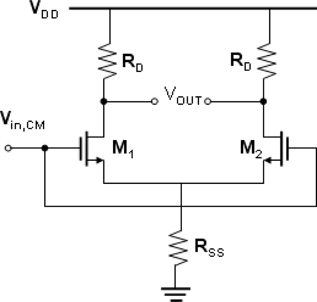
Figure 1 shows the schematic diagram of the typical common-mode differential circuit. The purpose of a differential amplifier is to sense the change in its differential input while rejecting changes in its common-mode input. The desired output is differential, and its variation should be proportional to the variation in the differential input. Variation in the common-mode output is undesired. The common-mode rejection ratio (CMRR) of a differential circuit measures the tendency of the device to reject the common signals for both input leads, and it indicates that the amount of the common-mode signal will appear in the measurement. The CMRR was defined as:
where
ADM denotes the circuit gain in the differential-mode, and
ACM-DM denotes the common-mode to differential-mode conversion. An important device parameter regarding the CMRR is the transconductance (g
m), which represents the sensitivity of the device. For a high g
m, a small change in V
GS results in a large change in I
DS at fixed V
DS, which provides higher measurement sensitivity. The transconductance is defined as in
Equation (2):
Assuming that the g
m1 and g
m2 are the transconductances of M1 and M2, respectively. We have:
where Δ
gm =
gm1 −
gm2.
According to
equations (1–
3), a transconductance mismatch of the ISFET/REFET pair will significantly degrade the CMRR, or in other words, the noise coming the from reference electrode metal/liquid interface will influence the measurement accuracy. An alternative method to increase the CMRR is to design high A
DM circuits; however, this requires a large number of additional components and increases the complexity of the circuit. Therefore, a transconductance matched ISFET/REFET pair will avoid the costs caused by a degraded CMRR and increase the measurement accuracy.
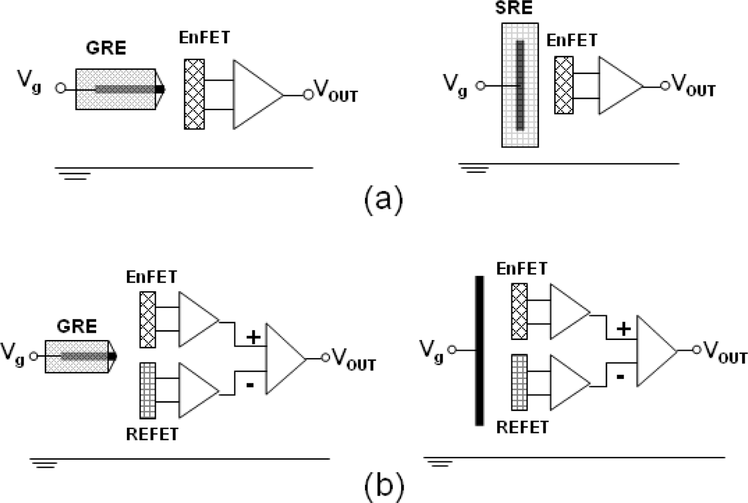
In this work, three sensor design steps were performed: firstly, the fabrication and characterization of the sole SRE, REFET and ureasable-EnFET. Then, the modifications of transconductance match for devices, and the last step was to evaluate the performances of the sensors with single-ended and two-ended differential combinations based on both the glass Ag/AgCl reference electrode (GRE) and QRE. Nafion™ was used as the common supporting matrix to immobilize functional materials—urease and photoresist—to fabricate the EnFETs, SREs and REFETs. The urea response, response time, storage time and the electrical properties of the sensors were also investigated.
3. Results and Discussion
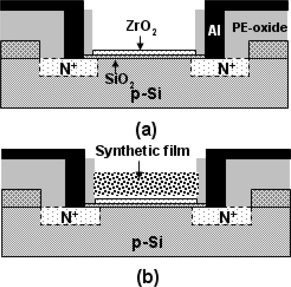
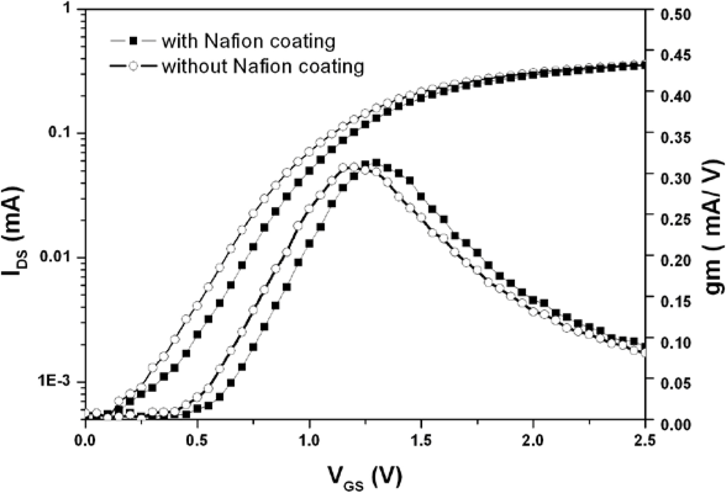
Figure 4 shows the I
DS-V
GS and the transconductance curves of the ZrO
2 gate ISFETs with and without Nafion™ coating. The result reveals that their curvatures are identical, which describes the electrical properties of the Nafion™. The I-V and g
m relationships of the ISFETs operating in linear region can be described as follows:
where
COV represents the overall capacitance of subsequent layers on sensing area, the μ represents the electron mobility of device and (W/L) represents the geometric ratio of gate. According to
equations (4) and
(5), since the devices were fabricated with the same size, material and process, the similar curvatures represent the fact that the additional Nafion™ membrane did not alter the overall capacitance of the gate layers.
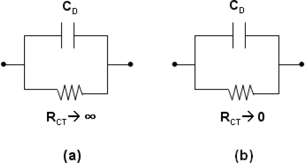
A way to visualize the electrical properties of a membrane is to make use of the simple equivalent circuit representation as shown in
Figure 5 [
28]. The R
CT denotes the charge-transfer resistor and C
D denotes the double-layer and membrane capacitor. If the resistor is very high, the capacitor charges up to the value of the potential difference set by the source.
This is the behavior of a polarizable (ion blocking) interface. To polarize an interface means to alter the potential difference across it. On the contrary, if the resistance in parallel with the capacitor is low, then any attempt to change the potential difference across the capacitor is compensated by charge leaking through the low-resistance path. This is the behavior of a nonpolarizable (ion unblocking) interface. With high conductivity and low impact on overall capacitance, the Nafion™ membrane is ion-unblocking and suitable as a supporting material
Figure 6 and
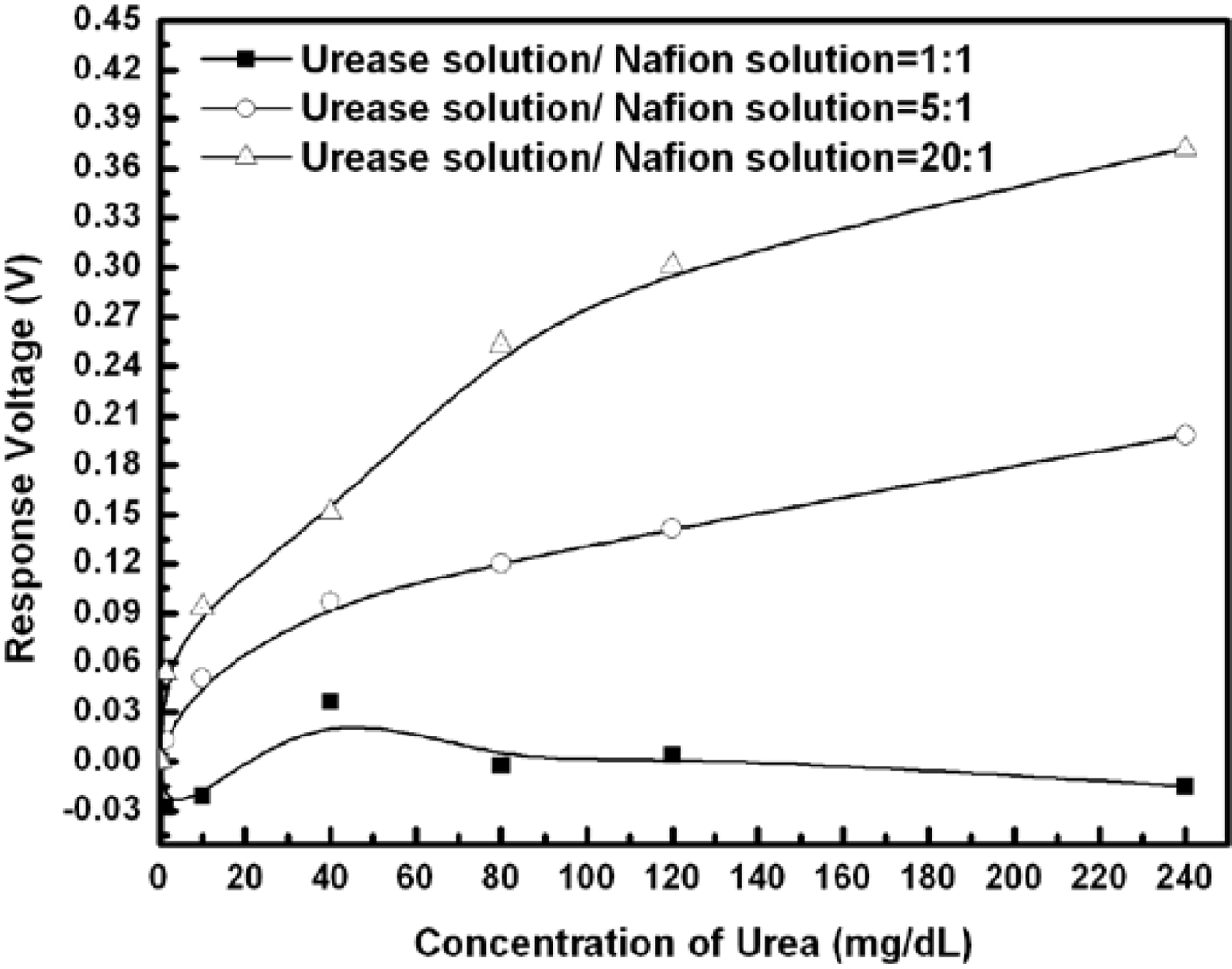
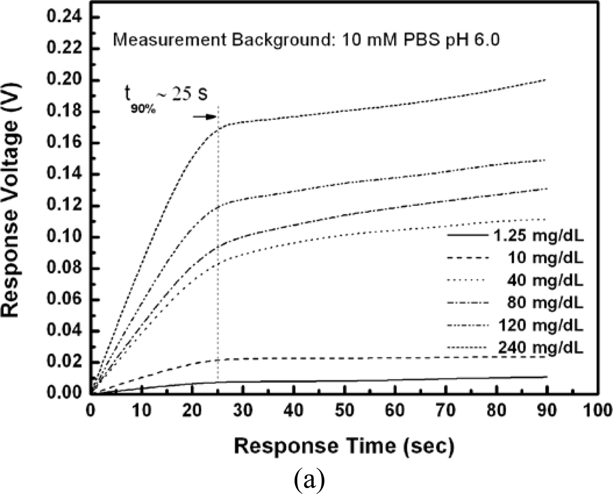
Table 1 show the responses and performance of the fabricated urease-EnFET measured with standard Ag/AgCl GRE. The concentration of the phosphate buffer solution was 10 mM and the tested urea concentrations were from 1.25 mg/dL to 240 mg/dL. The response performance depends not only on the amount of entrapped urease, but also on the initial pH, ambient buffer capacity and ionic strength of solutions as well as on the surface area, porosity and the physical characteristics of both the enzyme and the supporting material.
The results show that the urea sensitivity was proportional to the amount of urease entrapped in the membrane. Less urease entrapped in the membrane will degrade the urea detection ability. On the other hand, though the sensitivity and detection limits were enhanced with high enzyme loading, the device lifetime was limited due to the enzyme leakage. The entrapment process or membrane confinement of enzyme may be a purely physical caging or involve covalent binding. To enhance the chemical binding capability may increase the enzyme loading and achieve higher sensitivity. In addition to the consideration of the volumetric surface area available to the enzyme, which determines the maximum binding capacity, another consideration was that the nature of supporting material could have a considerable affect on an enzyme’s expressed activity and apparent kinetics. In this experiment, the sensor with the urease/Nafion ratio of 5:1 successfully performed the detection, and the urea responses were from 12.9 mV to 198.1 mV for urea concentrations from 8 mg/dL to 240 mg/dL. It demonstrated acceptable detection ability, response time and life time.
The urease biosensor based on the pH-ISFET detects pH change around the gate surface as a result of the urease catalyses the hydrolysis of urea according to the reaction:
According to [
29], the mechanisms involved in the response of pH-based enzyme sensors include the reaction kinetics of the biological-recognition processes and the mass transport. In the steady state, a balance between the rates of mass transport of the urea from bulk solution to the urease membrane, production or consumption of the hydrogen ions by the urease membrane and their transportation will be achieved, leading to a stable local pH change in the region of the membrane. We can then expect a change in the surface concentration of H
+ as a consequence of the change in the potential of the ISFET, and the concentration of urea is therefore measured indirectly. On the other hand, biosensors with indirect measurement are also impacted by the ambient buffer capacity and ionic strength, which are governed by many factors such as the concentration, dissociation constant and the ionic charge of electrolyte. For example, the increase of the phosphate buffer solution concentration will result in reduction of the EnFET sensitivity and change the linear part of the calibration curve, as reported in [
3,
30].
Figure 7(a) shows that the response times of all tests were within 25 seconds. The response time of EnFETs depends on the diffusion of hydrogen ions, the buffer capacity of system and the membrane properties and thickness.
In this experiment, the membranes were fabricated by the drop coating method, and the thickness of membranes were estimated to be 15 μm but not standardized. The membranes were thick; however, the response times were short for all tests, which represented the porosity and ion unblocking property of the membranes with Nafion™ as supporting matrix. Compared with the typical response time of 0.5∼3 minutes. [
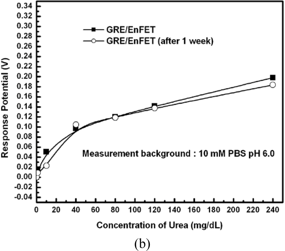
30], this result demonstrated the quick response characteristics of the proposed EnFET. The storage and repeatability performances of the proposed EnFETs are shown in
Figure 7(b) and
Table 2.
The results show that the urease entrapped membranes have good repeatability and long storage time.
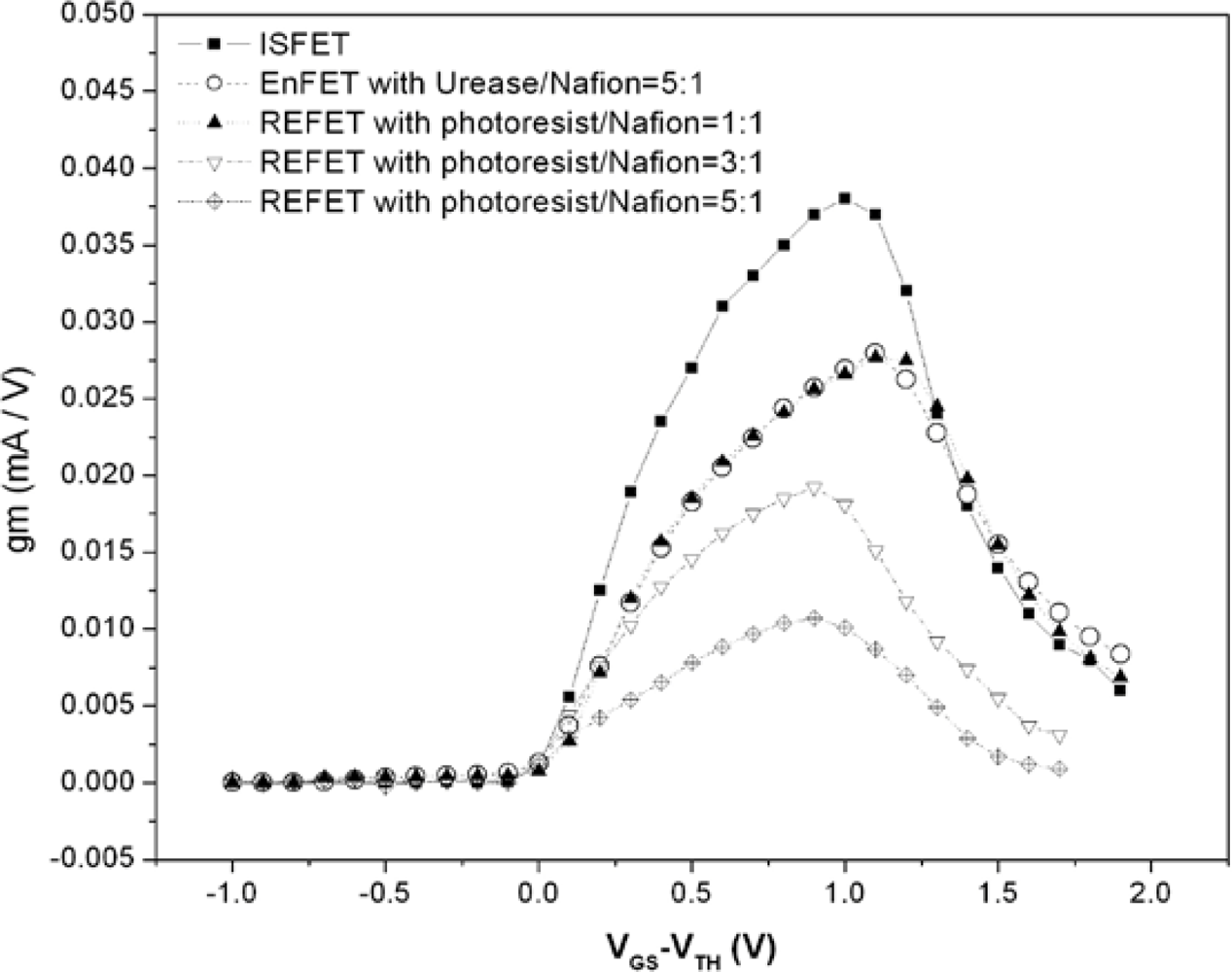
Figure 8 shows the electrical curves measured with GRE. The maximal g
m of the ISFET and EnFET were 38 and 27.9 mA/V, respectively. For REFETs, they were 27.7, 19.2 and 10.7 mA/V for the different photoresist/Nafion™ ratios of 1:1, 3:1 and 5:1. Among the devices, the EnFET and REFET curves with the photoresist/Nafion™ ratio of 1:1 were matched. In principle, the transconductance is mainly governed by the electron mobility, gate geometry and effective dielectric capacitance of the sensing layer. In this experiment, all devices were constructed on identical ISFETs, therefore their electron mobility and gate geometry were identical. Accordingly, the different g
m curves changed due to the capacitances change caused by the additional membrane. Since both types of membrane involved a similar concept of combining conductive and insulated materials to achieve nonpolarizable interfaces, hence it is possible to modify the overall conductance and capacitance to make FETs electrically match by adjusting their compositions and thickness,
etc.The result is particularly important for biosensors with differential readout designs. Most biosensors immobilize biomaterials with chemical, physical or mixed approaches, and the sensing membranes fabricated in each way certainly alter the original electrical properties. The fabrication of REFETs was the similar case. Transconductance mismatched input pairs could induce many issues, such as the CMRR degradation, DC offsets restrict linear dynamic ranges, low voltage gain and nonlinear problems,
etc. To solve those issues, extra components and complicated designs of circuits and device geometries are essential, therefore increasing the complexity of the readout electronics. Nevertheless, not all the problems induced by mismatch can be overcome. In many proposed novel differential readout circuit designs, the identical electrical properties of the bio-FETs/REFETs pair were assumed [
18,
31]; in other words, the previous device designs for electrical match can reduce the loadings for circuit designs. Consequently, the g
m match for devices design must be considered. The curves in
Figures 8 shows the results of designed REFETs with photoresist/Nafion™ ratios of 1:1, 3:1 and 5:1, respectively. It shows that curve of REFETs with photoresist/Nafion™ ratio of 1:1 can match the EnFET curve within the range of V
GS-V
TH = 0∼1.3 V, which provides wide ranges and larger g
m choices for readout circuits design considerations. In contrast, the other EnFET/REFET differential pairs only matched at V
GS-V
TH = 0∼0.2 V, in the so-called weak inversion region. As a result, the device sensitivity was relatively low and the dynamic operating range was restricted.
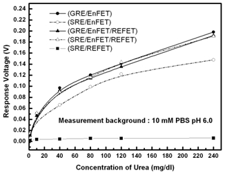
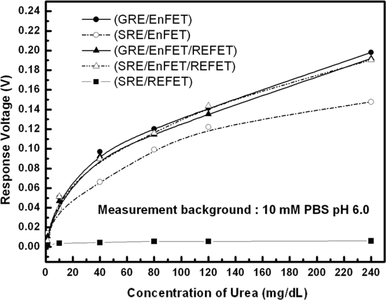
Figure 9 shows the urea responses of GRE/EnFET, SRE/EnFET, GRE/EnFET/REFET, QRE/EnFET/REFET and SRE/REFET combinations in this experiment. The zero urea response of SRE/REFET demonstrated its capability of being a biosensor reference system. Since the REFETs covered with nonpolarized membrane still possesses limited urea sensitivity of around 0.01 mV/mg/dL, the GRE/EnFET/REFET and GRE/EnFET have similar performance, except that the urea sensitivity was slightly lower for the two-ended pair. However, it demonstrated that the fabricated REFETs were practical for use as a reference system. On the other hand, the SRE/EnFET has the simplest on-chip structure with simple one-ended readout circuits. In this work, an altenative method was proposed to fabricate reference electrodes by coating ion-insensitive but ion-unblocking layers on the top of contact metal. This method suppressed the solid/liquid potential differences and provided a relatively stable reference potential. Nevertheless, the result reveals one main disadvantage in that the sensitivity was severely degraded. Comparing the combinations, the on-chip QRE/EnFET/REFET transconductance-match pair with two-ended differential readout circuits demonstrated comparable performance with GRE/EnFET and GRE/EnFET/REFET. Meanwhile, their storage time was more than 1 week. The results indicate the miniaturization of practical ISFET based biosensors can be realized.


