Fabrication and Characterization of CMOS-MEMS Thermoelectric Micro Generators

Abstract
:1. Introduction
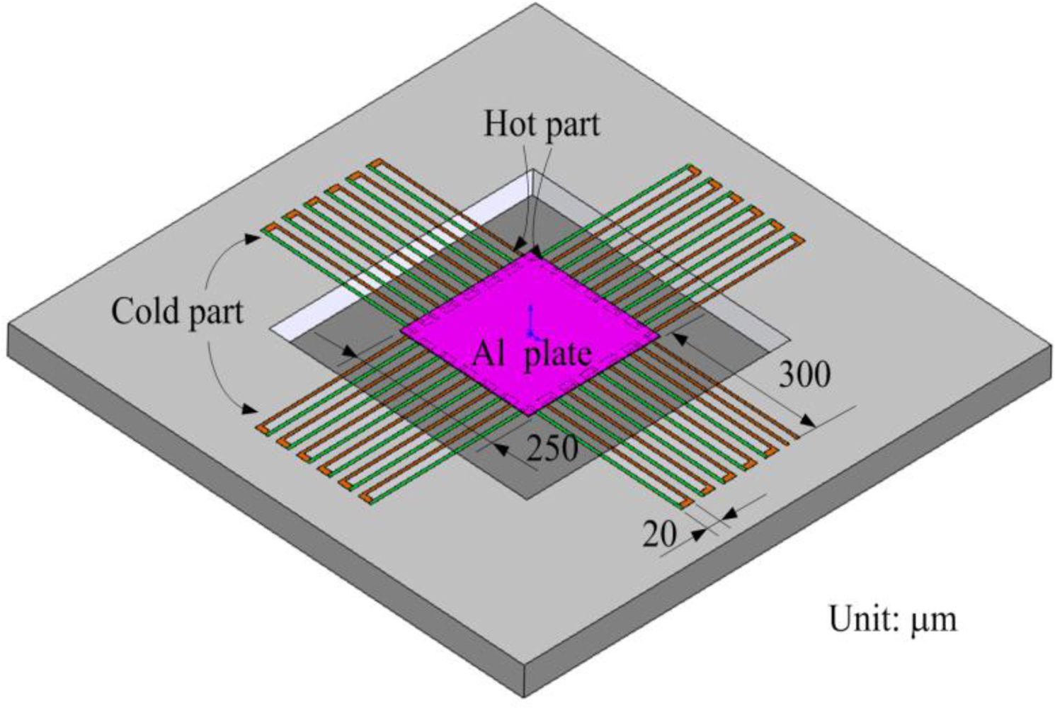
2. Design of the Generator
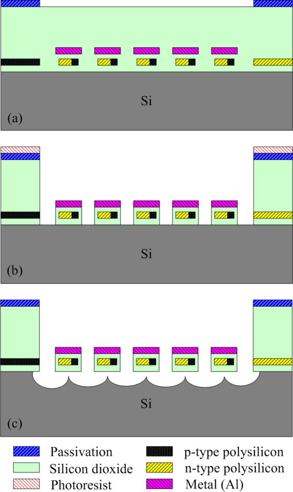
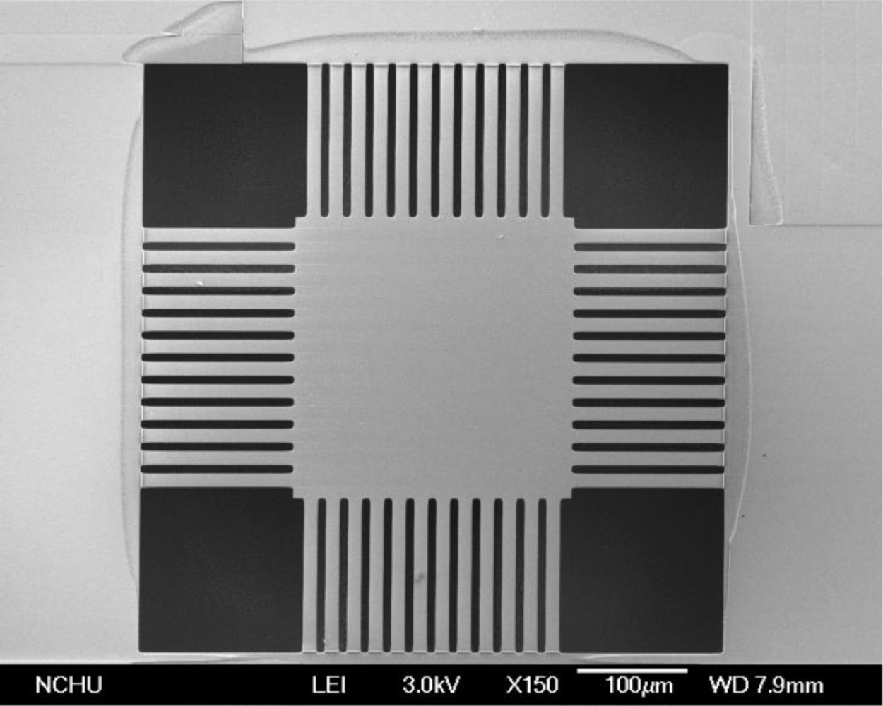
3. Fabrication of the Generator
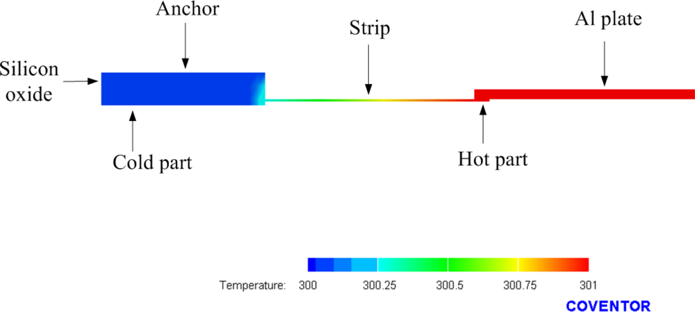
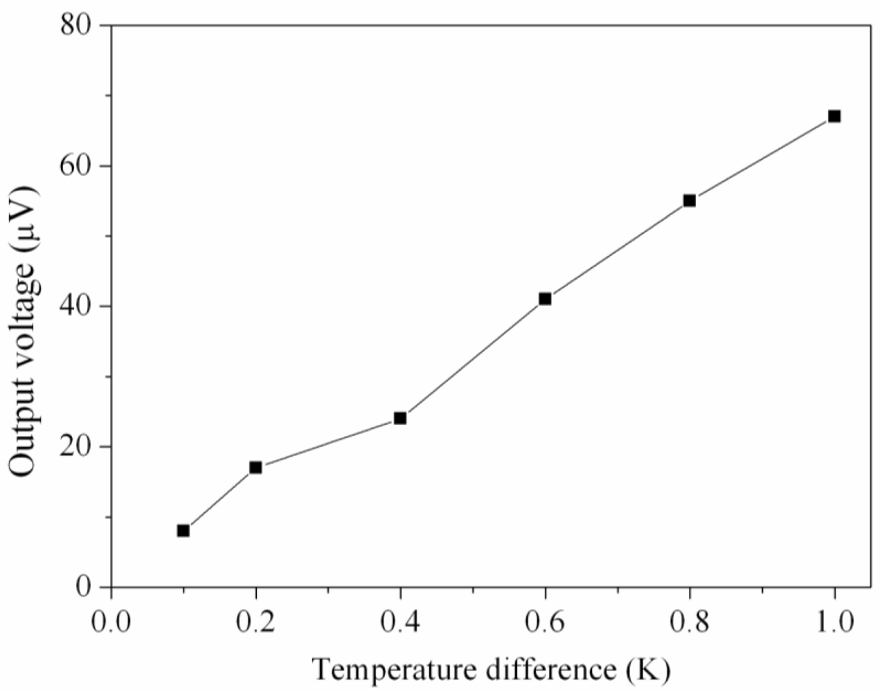
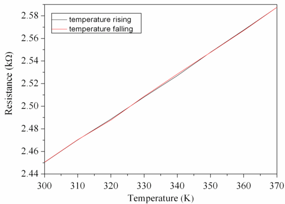
4. Results and Discussion
5. Conclusion
Acknowledgments
References
- Thakur, D.; Mithulananthan, N. Influence of constant speed wind turbine generator on power system oscillation. Electr. Power Compon. Syst 2009, 37, 478–494. [Google Scholar]
- Sodano, H.A.; Simmers, G.E.; Dereux, R.; Inman, D.J. Recharging batteries using energy harvested from thermal gradients. J. Intell. Mat. Syst. Struct 2007, 18, 3–10. [Google Scholar]
- Saket, R.K. Design, development and reliability evaluation of micro hydro power generation system based on municipal waste water. IEEE Elect. Power Energ. Conf. Energ. Innovat 2008. [Google Scholar] [CrossRef]
- Lokhtin, I.P.; Malinina, L.V.; Petrushanko, S.V.; Snigirev, A.M.; Arsene, I.; Tywoniuk, K. Heavy ion event generator HYDJET (HYDrodynamics plus JETs). Comput. Phys. Commun 2009, 180, 779–799. [Google Scholar]
- Nisan, S.; Benzarti, N. A comprehensive economic evaluation of integrated desalination systems using fossil fuelled and nuclear energies and including their environmental costs. Desalination 2008, 229, 125–146. [Google Scholar]
- Senturia, S.M. Microsystem Design; Kluwer Academic: Boston, MA, USA, 2001. [Google Scholar]
- Huesgen, T.; Woias, P.; Kockmann, N. Design and fabrication of MEMS thermoelectric generators with high temperature efficiency. Sens. Actuators, A 2008, 145–146, 423–429. [Google Scholar]
- Wang, W.; Jia, F.; Huang, Q.; Zhang, J. A new type of low power thermoelectric micro-generator fabricated by nanowire array thermoelectric material. Microelectron. Eng 2005, 77, 223–229. [Google Scholar]
- Sato, N.; Kuwabara, K.; Ono, K.; Sakata, T.; Morimura, H; Terada, J.; Kudou, K.; Kamei, T.; Yano, M.; Machida, K.; Ishii, H. Monolithic integration fabrication process of thermoelectric and vibrational devices for microelectromechanical system power generator. Jpn. J. Appl. Phys 2007, 46, 6062–6067. [Google Scholar]
- Qu, W.; Plötner, M.; Fischer, W.J. Microfabrication of thermoelectric generators on flexible foil substrates as a power source for autonomous Microsystems. J. Micromech. Microengineer 2001, 11, 146–152. [Google Scholar]
- Baltes, H.; Brand, O. CMOS-based microsensors and packaging. Sens. Actuator. A 2001, 92, 1–9. [Google Scholar]
- Kao, P.H.; Dai, C.L.; Hsu, C.C.; Lee, C.Y. Fabrication and characterization of a tunable in-plane resonator with low driving voltage. Sensors 2009, 9, 2062–2075. [Google Scholar]
- Dai, C.L.; Chen, Y.L. Modeling and manufacturing of micromechanical RF switch with inductors. Sensors 2007, 7, 2660–2670. [Google Scholar]
- Liu, M.C.; Dai, C.L.; Chan, C.H.; Wu, C.C. Manufacture of a polyaniline nanofiber ammonia sensor integrated with a readout circuit using the CMOS-MEMS technique. Sensors 2009, 9, 869–880. [Google Scholar]
- Dai, C.L.; Lu, P.W.; Wu, C.C.; Chang, C. Fabrication of wireless micro pressure sensor using the CMOS process. Sensors 2009, 9, 8748–8760. [Google Scholar]
- Strasser, M.; Aigner, R.; Lauterbach, C.; Sturm, T.F.; Franosch, M.; Wachutka, G.K.M. Micromachined CMOS thermoelectric generators as on-chip power supply. Sen. Actuator. A 2004, 114, 362–370. [Google Scholar]


| Material | Thickness (μm) | Thermal conductivity (pW/μm-K) |
|---|---|---|
| Al | 0.6 | 2.36 × 10⁸ |
| SiO2 | 5 | 1.42 × 10⁶ |
| Polysilicon | 0.3 | 3.2 × 10⁷ |
© 2010 by the authors; licensee Molecular Diversity Preservation International, Basel, Switzerland. This article is an open access article distributed under the terms and conditions of the Creative Commons Attribution license (http://creativecommons.org/licenses/by/3.0/).
Share and Cite
Kao, P.-H.; Shih, P.-J.; Dai, C.-L.; Liu, M.-C. Fabrication and Characterization of CMOS-MEMS Thermoelectric Micro Generators. Sensors 2010, 10, 1315-1325. https://doi.org/10.3390/s100201315
Kao P-H, Shih P-J, Dai C-L, Liu M-C. Fabrication and Characterization of CMOS-MEMS Thermoelectric Micro Generators. Sensors. 2010; 10(2):1315-1325. https://doi.org/10.3390/s100201315
Chicago/Turabian StyleKao, Pin-Hsu, Po-Jen Shih, Ching-Liang Dai, and Mao-Chen Liu. 2010. "Fabrication and Characterization of CMOS-MEMS Thermoelectric Micro Generators" Sensors 10, no. 2: 1315-1325. https://doi.org/10.3390/s100201315