Electrochemical Analysis of Conducting Polymer Thin Films

Abstract
:1. Introduction
2. Experimental Section
3. Results and Discussion
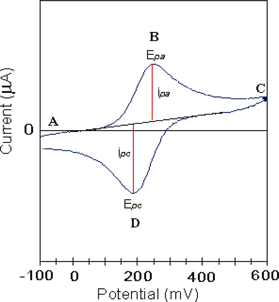
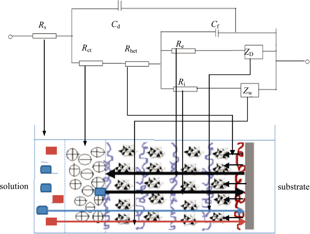
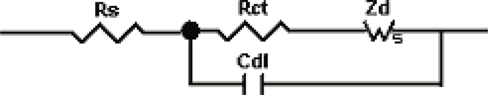
3.1. Theoretical Background
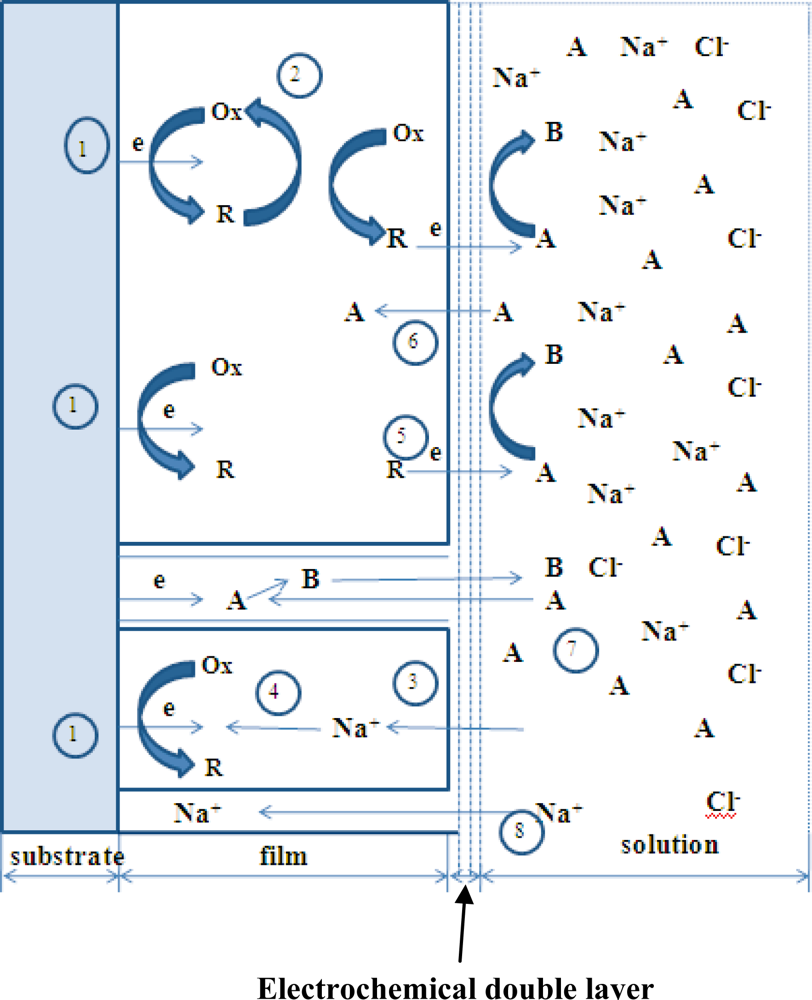
- Heterogeneous electron transfer to Ox to produce reduced form R.
- Electron transfer from R to another Ox in the film (electron diffusion or electron hopping in the film).
- Ionic diffusion of Na+/Cl− from solution into the film to maintain electro-neutrality.
- Ionic transfer (conduction) of Na+/Cl− within the film.
- Electron transfer from R to A at film/solution interface to form B.
- Mass transfer (linear diffusion) of A into the film under concentration gradient.
- Movement (migration) of A through a pinhole or channel in the film to substrate where it can be reduced.
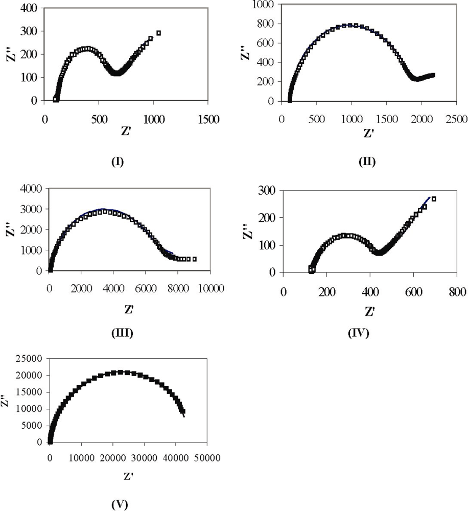
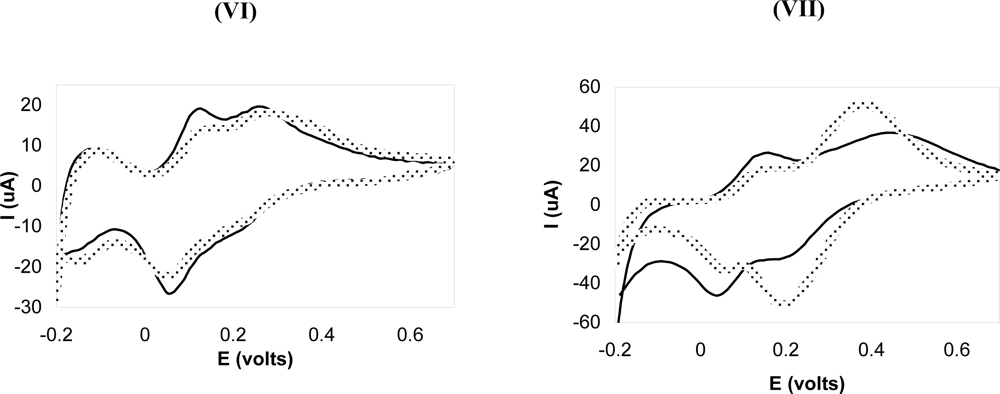
3.2. Electrochemical Analysis of Poly(p-phenylene vinylene) Films
4. Conclusions
Acknowledgments
References and Notes
- Bard, AJ; Faulkner, LR. Electrochemical Methods; Wiley: New York, NY, USA, 2000; Chapter 14. [Google Scholar]
- Lyons, MEG. Electroactive Polymer Electrochemistry, Part I: Fundamentals; Plenum Press: New York, NY, USA, 1994; ; Chapter 1. [Google Scholar]
- Decher, G; Hong, JD; Schmitt, J. Buildup of Ultrathin Multilayer Films by a Self-Assembly Process: III. Consecutively Alternating Adsorption of Anionic and Cationic Polyelectrolytes on Charged Surfaces. Thin Solid Films 1992, 210, 831–835. [Google Scholar]
- Lvov, Y; Decher, G; Mohwald, H. Assembly, Structural Characterization, and Thermal Behavior of Layer-by-Layer Deposited Ultrathin Films of Poly(vinyl sulfate) and Poly(allylamine). Langmuir 1993, 9, 481–486. [Google Scholar]
- Fery, A; Schöler, B; Cassagneau, T; Caruso, F. Nanoporous Thin Films Formed by Salt-Induced Structural Changes in Multilayers of Poly(acrylic acid) and Poly(allylamine). Langmuir 2001, 17, 3779–3783. [Google Scholar]
- Dubas, ST; Schlenoff, JB. Polyelectrolyte Multilayers Containing a Weak Polyacid: Construction and Deconstruction. Macromolecules 2001, 34, 3736–3740. [Google Scholar]
- Kovacevic, D; van der Burgh, S; de Keizer, A; Cohen Stuart, MA. Kinetics of Formation and Dissolution of Weak Polyelectrolyte Multilayers: Role of Salt and Free Polyions. Langmuir 2002, 18, 5607–5612. [Google Scholar]
- McAloney, RA; Dudnik, V; Goh, MC. Kinetics of Salt-Induced Annealing of a Polyelectrolyte Multilayer Film Morphology. Langmuir 2003, 19, 3947–3952. [Google Scholar]
- Izumrudov, V; Sukhishvili, SA. Ionization-Controlled Stability of Polyelectrolyte Multilayers in Salt Solutions. Langmuir 2003, 19, 5188–5191. [Google Scholar]
- Sui, Z; Schlenoff, JB. Phase Separations in pH-Responsive Polyelectrolyte Multilayers: Charge Extrusion versus Charge Expulsion. Langmuir 2004, 7, 6026–6031. [Google Scholar]
- Morgan, SE; Jones, P; Lamont, AS; Heidenreich, A; McCormick, CL. Layer-by-Layer Assembly of pH-Responsive, Compositionally Controlled (Co)polyelectrolytes Synthesized via RAFT. Langmuir 2007, 23, 230–240. [Google Scholar]
- Sun, J; Wu, T; Sun, Y; Wang, Z; Zhang, X; Shen, J; Cao, W. Fabrication of a Covalently Attached Multilayer via Photolysis of Layer-by-Layer Self-Assembled Films Containing Diazo-Resins. Chem. Commun 1998, 17, 1853–1854. [Google Scholar]
- Sun, J; Wu, T; Liu, F; Wang, Z; Zhang, X; Shen, J. Covalently Attached Multilayer Assemblies by Sequential Adsorption of Polycationic Diazo-Resins and Polyanionic Poly(acrylic acid). Langmuir 2000, 16, 4620–4624. [Google Scholar]
- Shi, F; Dong, B; Qiu, D; Sun, J; Wu, T; Zhang, X. Layer-by-Layer Self-Assembly of Reactive Polyelectrolytes for Robust Multilayer Patterning. Adv. Mater 2002, 14, 805–809. [Google Scholar]
- Vuillaume, PY; Joans, AM; Laschewsky, A. Ordered Polyelectrolyte “Multilayers”. 5. Photo-Cross-Linking of Hybrid Films Containing an Unsaturated and Hydrophobized Poly(diallylammonium) Salt and Exfoliated Clay. Macromolecules 2002, 35, 5004–5012. [Google Scholar]
- Park, MK; Deng, S; Advincula, RC. pH-Sensitive Bipolar Ion-Permselective Ultrathin Films. J. Am. Chem. Soc 2004, 126, 13723–13731. [Google Scholar]
- Olugebefola, SC; Ryu, SW; Nolte, AJ; Rubner, MF; Mayes, AM. Photo-cross-linkable Polyelectrolyte Multilayers for 2-D and 3-D Patterning. Langmuir 2006, 22, 5958–5962. [Google Scholar]
- Harris, JJ; DeRose, PM; Bruening, ML. Synthesis of Passivating, Nylon-Like Coatings through Cross-Linking of Ultrathin Polyelectrolyte Films. J. Am. Chem. Soc 1999, 121, 1978–1979. [Google Scholar]
- Yang, SY; Rubner, MF. Micropatterning of Polymer Thin Films with pH-Sensitive and Cross-linkable Hydrogen-Bonded Polyelectrolyte Multilayers. J. Am. Chem. Soc 2002, 124, 2100–2101. [Google Scholar]
- Welsh, ER; Schauer, CL; Santos, JP; Price, RR. In Situ Cross-Linking of Alternating Polyelectrolyte Multilayer Films. Langmuir 2004, 20, 1807–1811. [Google Scholar]
- Richert, L; Boulmedais, F; Lavalle, P; Mutterer, J; Ferreux, E; Decher, G; Schaaf, P; Voegel, JC; Picart, C. Improvement of Stability and Cell Adhesion Properties of Polyelectrolyte Multilayer Films by Chemical Cross-Linking. Biomacromolecules 2004, 5, 284–294. [Google Scholar]
- Niu, J; Shi, F; Liu, Z; Wang, Z; Zhang, X. Reversible Disulfide Cross-Linking in Layer-by-Layer Films: Preassembly Enhanced Loading and pH/Reductant Dually Controllable Release. Langmuir 2007, 23, 6377–6384. [Google Scholar]
- Jang, SY; Sotzing, GA; Marquez, M. Intrinsically Conducting Polymer Networks of Poly(thiophene) via Solid-State Oxidative Cross-Linking of a Poly(norbornylene) Containing Terthiophene Moieties. Macromolecules 2002, 35, 7293–7300. [Google Scholar]
- Jang, SY; Sotzing, GA; Marquez, M. Poly(thiophene)s Prepared via Electrochemical Solid-State Oxidative Cross-Linking. A Comparative Study. Macromolecules 2004, 37, 4351–4359. [Google Scholar]
- Kim, YS; Liao, KS; Jan, CJ; Bergbreiter, DE; Grunlan, JC. Conductive Thin Films on Functionalized Polyethylene Particles. Chem. Mater 2006, 18, 2997–3004. [Google Scholar]
- Friend, RH; Gymer, RW; Holmes, AB; Burroughes, JH; Marks, RN; Taliani, C; Bradley, DDC; Dos Santos, DA; Brédas, JL; Lögdlund, M; Salaneck, WR. Electroluminescence in Conjugated Polymers. Nature 1999, 397, 121–128. [Google Scholar]
- Brabec, CJ; Sariciftci, NS; Hummelen, JC. Plastic Solar Cells. Adv. Funct. Mater 2001, 11, 15–26. [Google Scholar]
- McGehee, MD; Heeger, AJ. Semiconducting (Conjugated) Polymers as Materials for Solid-State Lasers. Adv. Mater 2000, 12, 1655–1668. [Google Scholar]
- Fou, AC; Onitsuka, O; Ferreira, M; Rubner, MF; Hsieh, BR. Fabrication and Properties of Light-Emitting Diodes Based on Self-Assembled Multilayers of Poly(phenylene vinylene). J. Appl. Phys 1996, 79, 7501–7509. [Google Scholar]
- Onitsuka, O; Fou, AC; Ferreira, M; Hsieh, BR; Rubner, MF. Enhancement of Light Emitting Diodes Based on Self-Assembled Heterostructures of Poly(p-phenylene vinylene). J. Appl. Phys 1996, 80, 4067–4071. [Google Scholar]
- Nelson, CB; Vyas, RN; Mou, Y; Li, K; Rabalais, JW; Irwin, GM; Wang, B. Doping Poly(p-phenylene vinylene) with Phosphomolybdate through Layer-by-Layer Fabrication for Optoelectronic Applications. J Appl Phys 2007, 102. [Google Scholar]
- Brabec, CJ; Cravino, A; Zerza, G; Padinger, F; Sariciftci, NS; Kiebooms, R; Vanderzande, D; Hummelen, JC. Investigation of Photoinduced Charge Transfer in Composites of a Novel Precursor PPV Polymer and Fullerenes. Mater Res Soc Sympo Proc 1999, 598, BB3.25. [Google Scholar]
- Bradley, DDC. Precursor-Route Poly(p-phenylenevinylene): Polymer Characterisation and Control of Electronic Properties. J. Phys. D: Appl. Phys 1987, 20, 1389–1410. [Google Scholar]
- Wang, B; Vyas, RN; Shaik, S. Preparation Parameter Development for Layer-by-Layer Assembly of Keggin-type Polyoxometalates. Langmuir 2007, 23, 11120–11126. [Google Scholar]
- Bockris, JO’M; Conway, BE; White, RE. Modern Aspects of Electrochemistry No 14; Plenum Press: New York, NY, USA, 1982; ; Chapter 2. [Google Scholar]
- Barsoukov, E; Macdonald, JR. Impedance Spectroscopy: Theory, Experiment and Applications; John Wiley and Sons: New York, NY, USA, 2005; Chapter 1. [Google Scholar]
- Electrochemical Impedance Spectroscopy Theory: A Primer. Gamry: Warminster, PA, USA.
- Wallace, GG; Spinks, GM; Kane -Maguire, LAP; Teasdale, PR. Conductive Electroactive Polymers; CRC Press: Florida, USA, 2003; Chapter 1. [Google Scholar]
- Wise, DL; Wnek, GE; Trantolo, DJ; Cooper, TM; Gresser, JD. Electrical and Optical Polymer Systems; CRC Press: Coral Gables, FL, USA, 1998; Chapter 4. [Google Scholar]
- Deslouis, C; Musiani, MM; Tribollet, B. Free-Standing Membranes for the Study of Electrochemical Reactions Occurring at Conducting Polymer/Electrolyte Interfaces. J. Phys. Chem 1996, 100, 8994–8999. [Google Scholar]
- Deslouis, C; Musiani, MM; Rhazi, ME; Tribollet, B. Effect of pH on the Mediated Oxidation of [Fe(CN)6]4− at Polyaniline Film Electrodes. An Impedance Study. Synth. Met 1997, 60, 269–278. [Google Scholar]
- Sundfors, F; Bobacka, J; Ivaska, A; Lewenstam, A. Kinetics of Electron Transfer between Fe(CN)63−/4− and Poly(3,4-ethylenedioxythiophene) Studied by Electrochemical Impedance Spectroscopy. Electrochim. Acta 2002, 47, 2245–2251. [Google Scholar]
- Jasinski, P; Petrovsky, V; Suzuki, T; Anderson, HU. Impedance Studies of Diffusion Phenomena and Ionic and Electronic Conductivity of Cerium Oxide. J. Electrochem. Soc 2005, 152, J27–J32. [Google Scholar]
- Wang, B; Vyas, RN. Ion Transfer in Layer-by-Layer Films. Polymer Thin Films (IN-TECH) 2010. [Google Scholar]
- Barreira, SVP; García-Morales, V; Pereira, CM; Manzanares, JA; Silva, F. Electrochemical Impedance Spectroscopy of Polyelectrolyte Multilayer Modified Electrodes. J. Phys. Chem. B 2004, 108, 17973–17982. [Google Scholar]
- Silva, H; Morales, GV; Moura, C; Manzanares, A; Silva, F. Electrochemical Impedance Spectroscopy of Polyelectrolyte Multilayer Modified Gold Electrodes: Influence of Supporting Electrolyte and Temperature. Langmuir 2005, 21, 7461–7467. [Google Scholar]
- Durstock, MF; Rubner, MF. Dielectric Properties of Polyelectrolyte Multilayers. Langmuir 2001, 17, 7865–7872. [Google Scholar]
- Vyas, RN; Wang, B. Impedance Change Induced by Varying Polymerization Temperature of Conducting Polymer Thin Films. Electrochem. Commun 2008, 10, 416–419. [Google Scholar]
- Wéry, J; Dulieu, B; Baitoul, M; Paniez, P; Froyer, G; Lefrant, S. Thermal Conversion of PPV Precursor: Characterization at Different Stages of the Process. Synth. Metals 1999, 101, 194–195. [Google Scholar]
- Coronado, E; Gómez-Garcia, CJ. Polyoxometalate-Based Molecular Materials. Chem. Rev 1998, 98, 273–296. [Google Scholar]


| Sample | Polymerization condition | p-PPV (mM) | PAA (pH) | PSS (pH) | NaCl (M) | PMo12 (mM) | PDDA (mM) |
|---|---|---|---|---|---|---|---|
| I | 110 °C @ 2 h | 0.1 | - | 4.0 | 0.1 | - | - |
| II | 180 °C @ 4 h | 0.1 | - | 4.0 | 0.1 | - | - |
| III | 210 °C @ 12 h | 0.1 | - | 4.0 | 0.1 | - | - |
| IV | No heating | 0.1 | - | 4.0 | 0.1 | - | - |
| V | 210 °C @ 12 h | 0.1 | 4.0 | - | 0.1 | - | - |
| VI | 210 °C @ 12 h | 0.1 | - | 4.0 | 0.1 | 5 | 10 |
| VII | No heating | - | - | - | - | 5 | 10 |
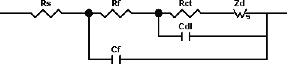
| Sample | Polymerization | Rs (Ω·cm2) | Rf (Ω·cm2) | Rct (Ω·cm2) | Cdl (μF·cm−2) | Cf (μF·cm −2) |
|---|---|---|---|---|---|---|
| I | 110 °C @ 2 h | 120 | 180 | 250 | 5.1 | 6.1 |
| II | 180 °C @ 4 h | 120 | 750 | 820 | 5.1 | 4.9 |
| III | 210 °C @ 12 h | 120 | 2300 | 2900 | 2.5 | 3.2 |
| IV | No heating | 130 | 115 | 170 | 9 | 6.2 |
| V | 210 °C @ 12 h | 128 | 20,000 | 24,000 | 5.2 | 5.9 |
© 2010 by the authors; licensee Molecular Diversity Preservation International, Basel, Switzerland. This article is an open-access article distributed under the terms and conditions of the Creative Commons Attribution license (http://creativecommons.org/licenses/by/3.0/).
Share and Cite
Vyas, R.N.; Wang, B. Electrochemical Analysis of Conducting Polymer Thin Films. Int. J. Mol. Sci. 2010, 11, 1956-1972. https://doi.org/10.3390/ijms11041956
Vyas RN, Wang B. Electrochemical Analysis of Conducting Polymer Thin Films. International Journal of Molecular Sciences. 2010; 11(4):1956-1972. https://doi.org/10.3390/ijms11041956
Chicago/Turabian StyleVyas, Ritesh N., and Bin Wang. 2010. "Electrochemical Analysis of Conducting Polymer Thin Films" International Journal of Molecular Sciences 11, no. 4: 1956-1972. https://doi.org/10.3390/ijms11041956