
MOF-Derived CeO2 Nanorod as a Separator Coating Enabling Enhanced Performance for Lithium–Sulfur Batteries
by
Hao Xiao
1,2,3,4,5,
Jian Qin
1,2,3,4,5,
Haodong Wang
2,3,4,5,
Xiaoxu Lai
2,3,4,5,
Pei Shi
2,3,4,5,
Chi Chen
2,3,4,5,* and
Dan Sun
2,3,4,5,* 1
College of Chemistry, Fuzhou University, Fuzhou 350116, China
2
CAS Key Laboratory of Design and Assembly of Functional Nanostructures, and Fujian Provincial Key Laboratory of Nanomaterials, Fujian Institute of Research on the Structure of Matter, Chinese Academy of Sciences, Fuzhou 350002, China
3
Xiamen Institute of Rare Earth Materials, Haixi Institutes, Chinese Academy of Sciences, Xiamen 361021, China
4
Xiamen Key Laboratory of Rare Earth Photoelectric Functional Materials, Xiamen 361021, China
5
Fujian College, University of Chinese Academy Sciences, Fuzhou 350002, China
*
Authors to whom correspondence should be addressed.
Molecules 2024, 29(8), 1852; https://doi.org/10.3390/molecules29081852
Submission received: 16 March 2024
/
Revised: 6 April 2024
/
Accepted: 13 April 2024
/
Published: 18 April 2024
(This article belongs to the Special Issue Multifunctional Metal Oxides: Synthesis and Applications)
Abstract
:The deployment of Li–S batteries in the commercial sector faces obstacles due to their low electrical conductivity, slow redox reactions, quick fading of capacity, and reduced coulombic efficiency. These issues stem from the “shuttle effect” associated with lithium polysulfides (LiPSs). In this work, a haystack-like CeO2 derived from a cerium-based metal-organic framework (Ce-MOF) is obtained for the modification of a polypropylene separator. The carbon framework and CeO2 coexist in this haystack-like structure and contribute to a synergistic effect on the restriction of LiPSs shuttling. The carbon network enhances electron transfer in the conversion of LiPSs, improving the rate performance of the battery. Moreover, CeO2 enhances the redox kinetics of LiPSs, effectively reducing the “shuttle effect” in Li–S batteries. The Li–S battery with the optimized CeO2 modified separator shows an initial discharge capacity of 870.7 mAh/g at 2 C, maintaining excellent capacity over 500 cycles. This research offers insights into designing functional separators to mitigate the “shuttle effect” in Li–S batteries.
1. Introduction
Boasting a high theoretical capacity (1675 mAh/g), high energy density (2600 Wh/kg), abundant availability (260 ppm in the Earth’s crust), low cost, and environmental benefits, lithium–sulfur (Li–S) batteries are seen as promising candidates for future energy storage systems [1,2,3,4]. Nevertheless, the commercial deployment of Li–S batteries faces challenges primarily due to the “shuttle effect” [5]. This phenomenon arises as soluble polysulfides (Li2Sx, 4 ≤ x ≤ 8) migrate from the sulfur cathode to the lithium metal anode during charge and discharge cycles due to concentration gradients and electric fields, leading to significant irreversible capacity loss and a diminished cycle life [6,7,8]. Additionally, the poor electrical conductivity of elemental sulfur and Li2S/Li2S2 results in low sulfur utilization and suboptimal rate performance, further constraining the potential applications of Li–S batteries. To tackle these challenges, numerous researchers have dedicated their efforts toward the development and implementation of modified separators [1].
Separator-modified materials are classified into nonpolar and polar materials, such as carbon (porous carbon spheres [9], carbon nanotubes [10], and graphene [11,12], etc.) and transition metal compounds (metal oxides [13], metal carbides [14], metal nitrides [15], and metal sulfides [16], etc.), respectively. Although carbon materials are highly conductive and enable efficient charge transfer during the conversion of LiPSs, polar materials are more widely used to suppress the “shuttle effect” due to their strong affinity to polar LiPSs.
Rare earth (RE) elements differ from transition metal elements due to their distinctive 4f shell electronic configurations, which result in unique physical and chemical properties. Among rare earth materials, rare-earth oxides (REOs) have garnered significant attention due to their applications in optics, electronics, magnetism, catalysis, and energy conversion [17,18,19]. In particular, CeO2, a representative REOs, has attracted interest in catalyzing the conversion of LiPSs. This is because CeO2 possesses exceptional catalytic activity, which arises from the reversible Ce4+/Ce3+ redox couple facilitated by surface oxygen vacancies [20]. This redox couple serves as an efficient active site that accelerates the conversion and decomposition of LiPSs at the interface. Recent research on REOs has focused on achieving nanometer-scale dimension to enhance the conversion of LiPSs. However, traditional synthesis methods for cerium oxide hard to avoid particle agglomeration, posing challenges in obtaining high-activity REOs. In light of this, it is worthwhile to explore alternative synthesis methods to obtain REOs with improved activity.
Metal-organic frameworks (MOFs) are typically composed of metal nodes and organic linkers, resulting in materials that are porous and possess tunable pore sizes and relatively large specific surface areas [21,22]. The unique frame structure of MOFs enables the use of MOFs as sacrifice templates, resulting in superior performance compared to conventional synthesis methods of REOs. The framework of MOFs enables the even dispersion of MOFs-derived oxides on its network, preventing the agglomeration of nano oxides. Furthermore, the large specific surface areas of MOFs promote the exposure of active sites of oxides. Additionally, the framework of MOFs facilitates channels for electron and ion transport, thereby accelerating the conversion of LiPSs [23,24,25,26].
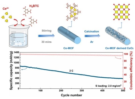
Drawing inspiration from the aforementioned factors, we developed a novel CeO2 material derived from MOFs, showcasing a haystack-like structure through the use of MOFs as sacrificial templates. This CeO2 material was utilized for enhancing the separators within Li–S batteries. The incorporation of a carbon network derived from the organic framework of Ce-MOF aids in promoting electron transfer during the conversion of LiPSs, thereby enhancing the rate capability of the Li–S batteries. Additionally, the CeO2 exhibits remarkable electrocatalytic activity, facilitating the acceleration of redox reactions of LiPSs and effectively mitigating the shuttle effect within the batteries. The Li–S battery assembled with a CeO2 modified separator exhibits a high specific capacity of 1260 mAh/g at a rate of 0.2 C, an excellent rate performance of 662.8 mAh/g at a rate of 5 C, and a capacity decay of only 0.1% per cycle after 500 cycles at a rate of 2 C, demonstrating significant cycling stability.
2. Results and Discussion
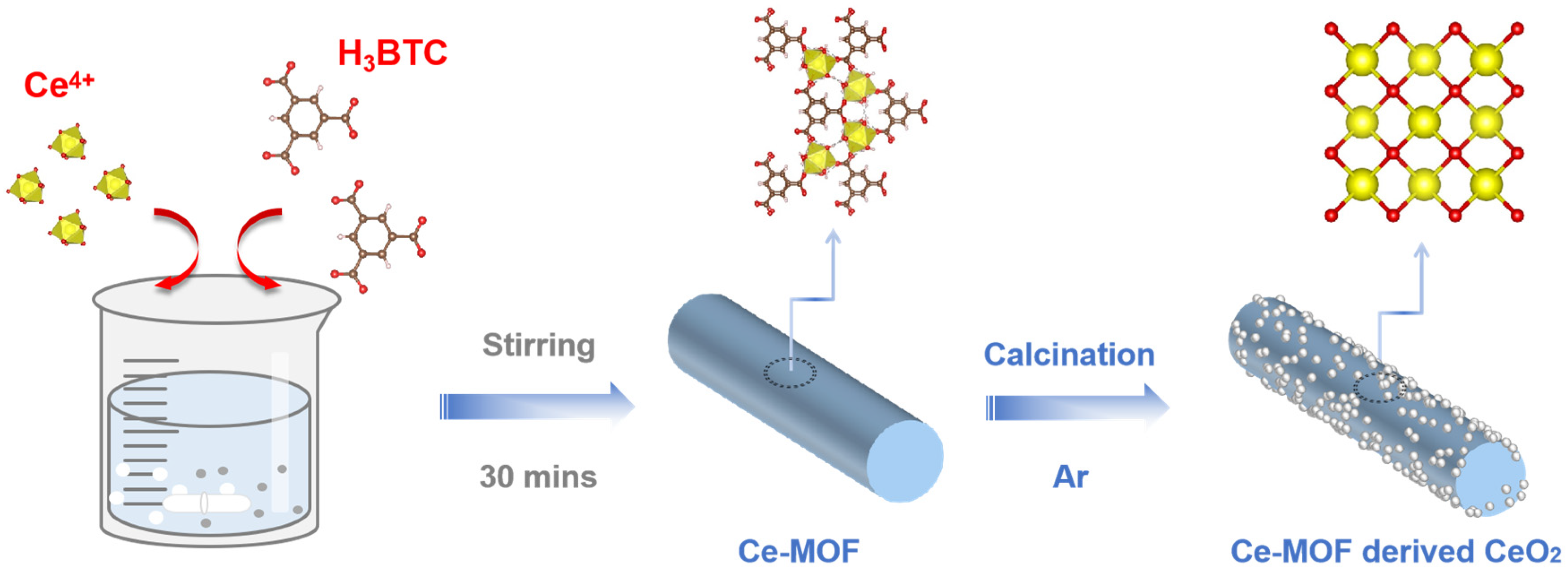
The progresses of Ce-MOF and CeO2 synthesis are illustrated in Scheme 1. The Ce-MOF is prepared by a hydrothermal method with Ce(NO3)3·6H2O and 1,3,5-Benzenetricarboxylic acid as raw materials. To obtain the CeO2, the Ce-MOF is used as precursor calcinated at 800 °C under an argon atmosphere. Subsequently, the CeO2 separator is produced by a common Li–S batteries slurry coating method.
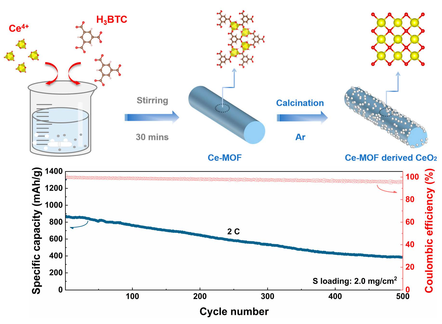
Transmission electron microscopy (TEM) and scanning electron microscopy (SEM) analyses are performed to reveal the appearance differences between Ce-MOF and CeO2, as depicted in Figure 1. The SEM images (Figure 1a,b) demonstrate that CeO2 retains a haystack-like morphology reminiscent of the Ce-MOF precursor, indicating that the calcined CeO2 maintains the structural characteristics of Ce-MOF. Notably, the haystack-like CeO2 is composed of nanorods with an average diameter ranging from 40 to 80 nm, as depicted in Figure 1c. Furthermore, the uniform distribution of carbon, oxygen, and cerium elements depicted in the SEM image (Figure 1d) and the corresponding elemental mappings (Figure 1e–g) confirms the retention of the carbon component in Ce-MOF-derived CeO2. The morphological features and size of CeO2 observed in the TEM image (Figure 1h) correspond with the findings from the SEM images. Furthermore, the high-resolution TEM (HRTEM) imagery (seen in Figure 1i) shows lattice fringe spacings of 0.314, 0.271, 0.192, and 0.166 nm, aligning with the (111), (200), (220), and (311) planes of CeO2, respectively [27,28]. The selected area electron diffraction (SAED) pattern in Figure 1j illustrates the (111), (200), (220), and (311) facets of CeO2, further corroborating the successful synthesis of CeO2 derived from Ce-MOF.
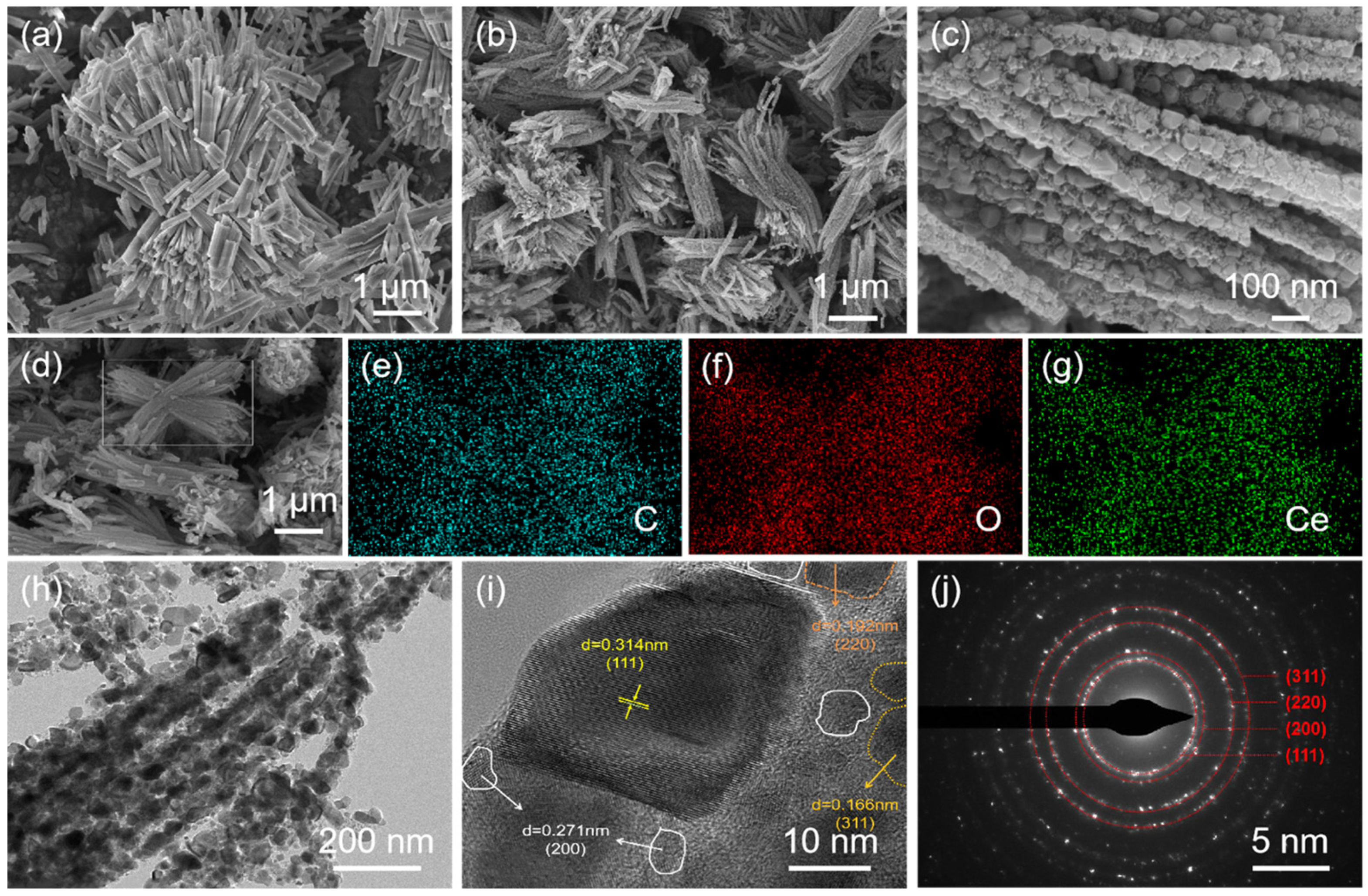
Figure 2a displays the X-ray diffraction (XRD) patterns of Ce-MOF and CeO2. The diffraction peaks of Ce-MOF align closely with previous research [27] and the peaks of the synthesized CeO2 can be indexed well with CeO2 (JCPDS: 43-1002). To study the bonding features of Ce-MOF and CeO2, FT-IR spectroscopy was performed and the results are shown in Figure 2b. For Ce-MOF, two peaks at around 1610 cm−1 and 1540 cm−1 can be attributed to stretching vibrations of asymmetric carboxylate, while the peaks at around 1430 cm−1 and 1370 cm−1 are assigned to symmetric carboxylate anions. The peak at 3330 cm−1 belongs to water (O–H). After calcination, the peak located at 533 cm−1 in the spectrum of CeO2 is classified as to the Ce–O vibration that is in accord with the Ce-MOF. The specific surface areas of Ce-MOF and CeO2 are explored using Brunauer–Emmett–Teller (BET) analysis through N2 adsorption–desorption isotherms, as presented in Figure 2c. Compared to the Ce-MOF, the specific surface areas of CeO2 are increased from 21.20 m2/g to 147.84 m2/g, leading to stronger adsorption ability to LiPSs. The pore size distributions in Figure S2 reveal that CeO2 has a porous structure.
The chemical states of the elements present on the CeO2 surface are examined using X-ray photoelectron spectroscopy (XPS). Figure 2d shows three peaks in the C 1s spectrum, which is assigned to C–C, C–O, and O–C=O (284.7, 285.4, and 289.3 eV), respectively [19]. The O 1s spectrum (Figure 2e) displays three peaks at 529.9, 530.3, and 532.2 eV, which could be indexed to lattice oxygen (OL), O2− ions in surface oxygen vacancies (OV), and chemisorbed oxygen species (OC), respectively [29]. As depicted in Figure 2f, the high-resolution Ce 3d spectrum is fitted into eight peaks as follows: V (882.8 eV), V′ (885.2 eV), V″ (889.6 eV), V‴ (898.5 eV), U (901.2 eV), U′ (902.9 eV), U″ (908.1 eV), U‴ (917.2 eV) [29,30]. The binding energies of the peaks V/U, V″/U″, and V‴/U‴ correspond to the standard spectra of Ce4+, while the binding energies of V′ and U′ correspond to Ce3+. This demonstrates the presence of Ce4+/Ce3+ redox couples in the CeO2 material.
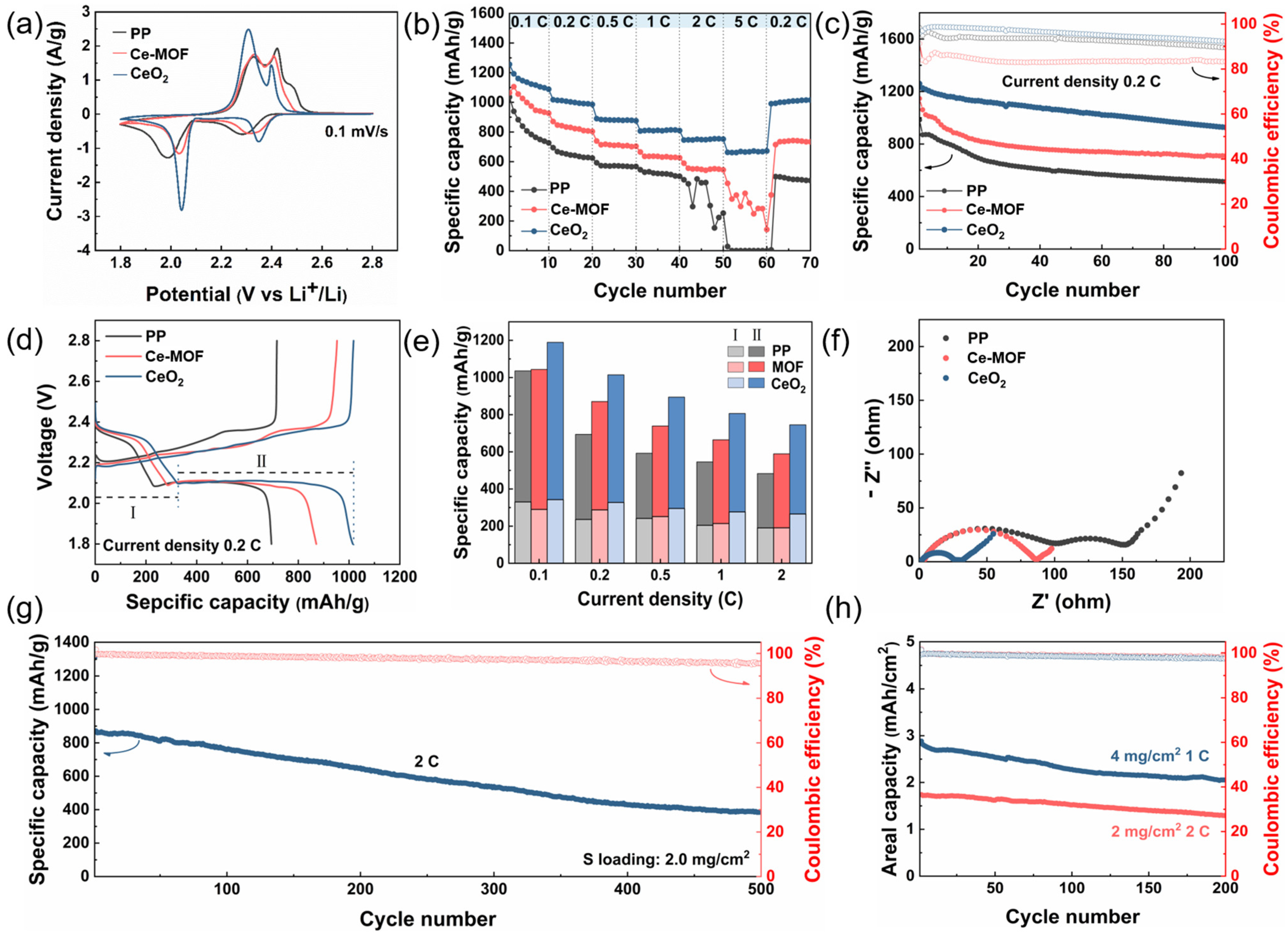
The SEM images displayed in Figure S3 reveal the even distribution of Ce-MOF and CeO2 on the PP separator in a 3D structure, which functions as a physical barrier against LiPSs. The cyclic voltammetry (CV) curves provided in Figure 3a show the performance of Li–S batteries utilizing PP, Ce-MOF, and CeO2 modified separators under a scan rate of 0.1 mV/s within a voltage window of 1.8 to 2.8 V (vs. Li+/Li). The reduction peaks at 2.3 and 2.05 V signify the reduction of sulfur (S8) to long-chain soluble LiPSs (Li2Sx, where 4 ≤ x ≤ 8), transitioning into short-chain insoluble Li2S2/Li2S for both Ce-MOF and CeO2 [31,32]. On the contrary, the oxidation peaks at approximately 2.3 and 2.4 V correspond to the reverse process of Li2S/Li2S2 conversion back to S8 [33]. Notably, batteries with CeO2 modified separators demonstrate higher peak currents, reaching around 2 A/g, and a smaller polarization. These outcomes suggest that the incorporation of CeO2 enhances the redox reactions of polysulfides and diminishes polarization.
Figure 3b depicts the rate performance of cells with PP and modified separators across current densities from 0.1 to 5 C. The cell equipped with a CeO2 modified separator exhibits remarkable specific capacities of 1256.2, 1017.7, 890.1, 806.4, 745.9, and 662.8 mAh/g at 0.1, 0.2, 0.5, 1, 2, and 5 C, respectively, outperforming cells with PP and Ce-MOF modified separators. Conversely, the PP and MOF separators demonstrate poor stability at current densities of 2 C and 5 C. Interestingly, upon reducing the current density from 5 C to 0.2 C, the cell with a CeO2 modified separator displays outstanding reversibility and stability, rebounding to 990.9 mAh/g, equivalent to approximately 97.4% of the initial value. Furthermore, Figure 3c illustrates the cycling performances of cells utilizing various separators at a current density of 0.2 C. Notably, the cell featuring a CeO2 modified separator showcases superior cycling capability, initiating with a specific capacity of 1260 mAh/g and the highest coulombic efficiency. Even after 100 cycles, the specific capacity of the cell with a CeO2 modified separator remains at 926.9 mAh/g, significantly exceeding those with Ce-MOF modified (709.2 mAh/g) and PP (513.2 mAh/g) separators.
The galvanostatic discharge/charge (GDC) profiles for cells incorporating various separators at current densities from 0.1 C to 2 C are detailed in Figure 3d and Figure S4. Notably, Figure 3d shows two distinct discharge plateaus at a current density of 0.2 C. The initial plateau relates to the conversion of S8 to long-chain soluble LiPSs (Li2Sx, 4 ≤ x ≤ 8) (I), followed by the conversion of these long-chain LiPSs to short-chain Li2S2/Li2S (II). Subsequently, Figure 3e and Table S1 present a summary of the specific capacities associated with plateaus I and II and the ratio between plateau II and the discharge capacity at current densities ranging from 0.1 C to 2 C. Notably, despite capacity fade with increasing current rate due to an insufficient reduction of LiPSs, cells with PP, Ce-MOF, and CeO2 separators exhibit around 60.5%, 67.6%, and 64.4% of the discharge capacity corresponding to plateau II at a current density of 2 C, respectively. This observation suggests that the modified separators facilitate the conversion of long-chain Li2S4 to Li2S2/Li2S [34]. Furthermore, the electrochemical impedance spectra (EIS) of cells with different separators are depicted in Figure 3f. Of particular interest is the cell with a CeO2 modified separator, which demonstrates the lowest charge transfer resistance (Rct). This outcome indicates the enhanced charge transfer kinetics of CeO2, potentially attributed to the carbon component within CeO2 derived from Ce-MOF.
For Li–S batteries to reach commercialization and large-scale application, parameters like long-term cycling stability and high areal capacity are essential. Demonstrated in Figure 3g, the cell employing a CeO2 modified separator showed remarkable long-term cycling stability during tests at a current density of 2 C with a sulfur loading of 2 mg/cm2. Initially, it delivered a specific capacity of 870.7 mAh/g at 2 C and experienced a capacity decay of only 0.1% per cycle after 500 cycles, all while maintaining a stable coulombic efficiency exceeding 95%. In addition, to investigate the high areal capacity of cell with a CeO2 modified separator, the areal sulfur mass loading is increased to 4 mg/cm2 (Figure 3h). High initial areal capacity of 1.75 and 2.89 mAh/cm2 are achieved at the current density of 2 C and 1 C, and retained the areal capacities of 1.30 and 2.05 mAh/cm2 after 200 cycles, demonstrating that the CeO2 modified separator possesses the potential in Li–S batteries applications.
To investigate the influence of CeO2 modified separator thickness on the performance of Li–S batteries, cells with varying thicknesses of CeO2 modified separators (referred to as CeO2-25, 50, 75, and 100) were prepared using a doctor’s blade. The actual coating thicknesses of CeO2-25, CeO2-50, CeO2-75, and CeO2-100 were measured as 12.84, 14.33, 16.19, and 18.42 μm, respectively, as shown in Figure S5 and Table S2. The rate performances of cells with different thicknesses of CeO2 modified separators are illustrated in Figure 4a, highlighting that the cell with the CeO2-75 modified separator exhibited the highest specific capacity of 1256.2 mAh/g at 0.1 C and 662.8 mAh/g at 5 C. Upon reducing the current density to 0.2 C, the specific capacity of the cell with the CeO2-75 modified separator increased to 990.9 mAh/g, surpassing those of cells with CeO2-25, 50, and 100.
In addition, the cycling performances of the cell with CeO2 modified separators with different thicknesses are investigated in Figure 4b. The maintained discharging capacity of the cell with the CeO2-75 modified separator after 100 cycles at current density 0.2 C is 926.9 mAh/g, much higher than those of cells with the CeO2-25 (698.8 mAh/g), CeO2-50 (776.6 mAh/g), and CeO2-100 (851.0 mAh/g) modified separator. As shown in Figure 4c, the CV curves of batteries using CeO2-75 modified separators demonstrate the highest current intensity, and among all samples, CeO2-75 has the highest reduction peak potential and the lowest oxidation peak potential, with a polarization value of about 250 mV, further indicating its fastest reaction kinetics. As depicted in Figure S6, the CV curves from the first to fifth cycles of the cell with CeO2-75 at a scan rate of 0.1 mV/s are measured, showing that there is no significant change in the potential of redox peaks, thereby suggesting superior electrochemical stability [35].
As illustrated in Figure 4d, the electrochemical impedance spectra of cells with various thicknesses of CeO2 modified separators are investigated. Among them, the cell with the CeO2-75 modified separator shows the smallest Rct, revealing the fast kinetics of LiPSs redox. The value of Rct varies in a trend in which CeO2-75 > CeO2-100 > CeO2-50 > CeO2-25. Based on all electrochemical results of cells with various thicknesses of CeO2 modified separators, we found that increasing the thicknesses of CeO2 coatings can restrain the “shuttle effect” and accelerate the conversion of LiPSs to some extent. However, when the coating is too thick, the transmission of electrons and ions will be inhibited, leading to worse electrochemical performances. Therefore, the thicknesses of modified separators would be worth further attention in future research.
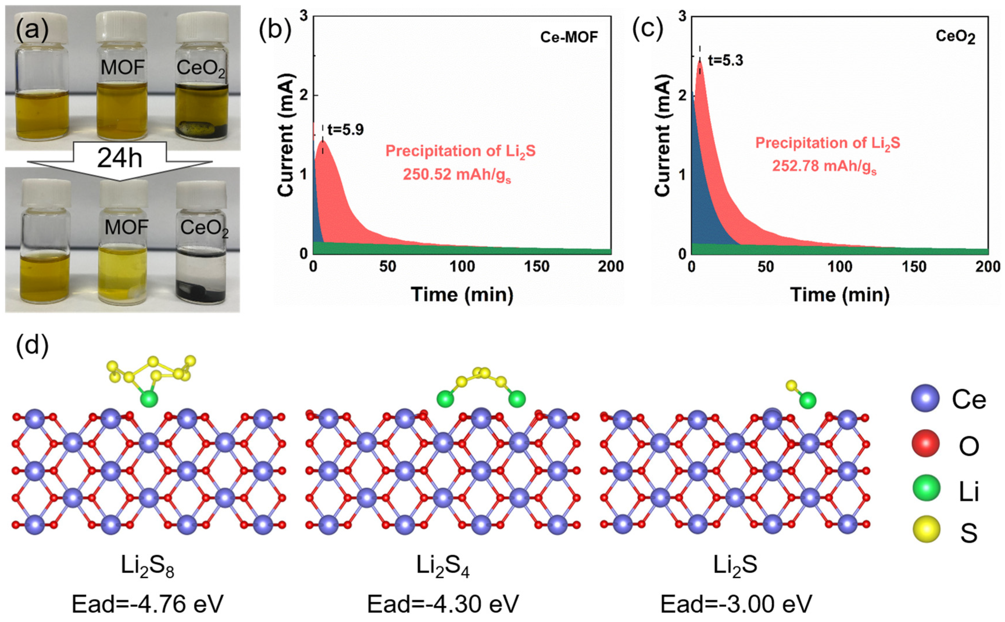
As shown in Figure 5a, the polysulfide adsorption experiment is conducted to verify the chemical binding ability of Ce-MOF and CeO2 [36]. Samples of 10 mg were added into 3 mL of 5 mM Li2S9 solution. The Li2S9 solution with CeO2 become complete colorless while the Li2S9 solution with Ce-MOF is light yellow after 24 h, demonstrating that CeO2 exhibits much stronger chemical interactions with LiPSs than Ce-MOF. The formation mechanism of Li2S is investigated by Li2S nucleation experiments as shown in Figure 5b,c. The peak areas in red, blue, and green represent the precipitation of Li2S, the reduction of Li2S8, and the reduction of Li2S6, respectively. Compared to the cell with the Ce-MOF modified separator, a sharp nucleation peak for the cell with the CeO2 modified separator appears earlier, demonstrating a faster nucleation ability of the Li2S [37,38]. The capacities of the precipitated Li2S on the cell with Ce-MOF and CeO2 modified separators are calculated as 250.52 and 252.78 mAh/g, respectively.
Furthermore, density functional theory (DFT) simulations are conducted to certify the chemical interaction between CeO2 and LiPSs. Figure 5d infers that the intermediate Li2S8, Li2S4, and Li2S are chosen as the computational models to calculate the adsorption energy. The relaxed configurations of Li2S8, Li2S4, and Li2S adsorbed on the surface of CeO2 deliver the binding energies of −4.76, −4.30, and −3.00 eV, respectively. These values are comparable or superior to other materials as reported elsewhere [7,9], indicating a strong chemical adsorption. Additionally, compared to Li2S, CeO2 has lower binding energy to the long-chain LiPSs, demonstrating the stronger the polar–polar interactions between CeO2 and LiPSs [39]. Overall, the DFT calculation results suggest that the CeO2 can effectively capture LiPSs.
3. Materials and Methods
3.1. Synthesis of the MOF
The Ce-MOF was synthesized by a conventional hydrothermal method as reported elsewhere [27]. A solution of Ce(NO3)3·6H2O at 0.5 M concentration was initially prepared. A mixture of deionized water and ethanol (99%) was used as the solvent, with PVP (10 wt%) and 0.5 mmol of 1,3,5-Benzenetricarboxylic acid dissolved in it. The Ce(NO3)3·6H2O solution was then gradually mixed into this solvent under vigorous stirring at ambient temperature for 30 min. After stirring, the mixture underwent filtration and was washed with deionized water and ethanol to obtain the Ce-MOF powder.
3.2. Synthesis of the CeO2
The CeO2 powder was synthesized through a high-temperature calcination process. The preobtained Ce-MOF powder was placed in a tube furnace and calcined at 800 °C for 5 h under an argon gas flow, with the heating rate set at 5 °C/min, as determined by the TG curve (Figure S1).
3.3. Synthesis of CeO2 Coating Separator
A mixture containing CeO2 powder, Super P, and PVDF in an 8:1:1 weight ratio was prepared as a slurry and coated onto a polypropylene (PP) separator using a doctor blade technique. This coated separator was then dried in a vacuum oven at 50 °C overnight. The resultant modified separator was cut into circles for cell assembly.
3.4. Sulfur Cathode Preparation
The sulfur mass loading of the cathodes is 1.0–1.5 mg/cm2. The sulfur cathodes were crafted by spreading a slurry mixture of sulfur powder, Super P, CMC, and SBR (55:35:5:5 weight ratio) onto an aluminum substrate. This mixture was dried in a vacuum oven at 80 °C for 12 h, resulting in cathodes with a sulfur mass loading between 1.0–1.5 mg/cm2, ready for cell assembly.
3.5. Electrochemical Measurements
For assessing the electrochemical performance of the modified separators, type CR2025 coin cells were constructed with lithium metal serving as the anode. The electrolyte, freshly prepared with lithium bis((trifluoromethyl)sulfonyl) imide (1 M) in 1,3-dioxolane (DOL) and 1,2-dimethoxyethane (DME) containing LiNO3 (1 wt%) with a volume ratio of 1:1, was carefully manipulated in an argon-filled glove box. Subsequently, LAND battery systems were employed for galvanostatic charge/discharge testing and rate performance evaluation. Cyclic voltammetry (CV) curves within a 1.8–2.8 V window and electrochemical impedance spectroscopy (EIS) measurements were conducted at a 0.1 mV/s scan rate and a 10 mHz to 100 kHz frequency range on an electrochemical workstation (MULTI AUTOLAB M204).
3.6. Materials Characterization
To certify the structure of the obtained samples, X-ray powder diffraction (XRD, Miniflex 600, Rigaku, Tokyo, Japan) patterns were measured with the Cu-Kα radiation at a scan rate of 5°/min. The calcined temperature range, essential for this study, was determined using thermogravimetric analysis (TAG, TGA/DSC) in an Ar atmosphere, spanning from 30 to 1000 °C. Fourier-transformed infrared spectra (FT-IR, Nicolet iS 50, Thermo Scientific, Waltham, MA, USA) were then employed for a more comprehensive analysis of the chemical bonds. N2 adsorption isotherms (Autosorb-iQ, Anton Paar, Boynton Beach, FL, USA) were utilized to determine the Brunauer–Emmett–Teller (BET) surface area. The sample morphology was further analyzed using a field-emission scanning electron microscope (FESEM, Apreo S LoVac, Thermo Scientific, Waltham, MA, USA) at a 5.0 kV acceleration voltage, equipped with an Energy Dispersive Spectrometer (EDS), and a transmission electron microscope (TEM, FEI Talos F200s, FEI, Hillsboro, OR, USA). Finally, to gain insights into the chemical compositions, X-ray photoelectron spectroscopy (XPS, Axis Supra, Shimadzu, Tokyo, Japan) was conducted.
3.7. Polysulfides Adsorption Experiment
Li2S9 solution was prepared by sulfur reaction with Li2S (n:n = 8:1) in DOL/DME (1:1) under 50 °C overnight. Appropriate MOF and CeO2 powder were added into 3 mL Li2S9 solution. A blank group without any powder was measured. All processes are carried out in an argon-filled glove box.
3.8. Measurement of the Li2S Nucleation
In the cell configuration, two pieces of carbon cloth served as electrodes, which were isolated by a separator modified with either Ce-MOF or CeO2. Specifically, on the cathode, 20 μL of Li2S8 (2.5 mM) was introduced, whereas on the anode, 20 μL of blank electrolyte was dispensed. The cell underwent a galvanostatic discharge process at a current of 0.112 mA until reaching a voltage of 2.06 V. Subsequently, it was maintained at 2.05 V until the current dwindled to 10−5 A.
3.9. Computational Method
The first-principles computations in this study were conducted using density functional theory (DFT) within the Vienna Ab Initio Simulation Package (VASP 5.4) [40]. To ensure accurate results, the Perdew–Burke–Ernzerhof (PBE) parametrization of the generalized gradient approximation (GGA) and projector-augmented wave (PAW) were employed [41,42]. A 2 × 2 × 1 Γ-centered k-mesh was chosen to represent the Brillouin zone, with a plane-wave energy cutoff of 520 eV. Energy convergence criteria were set at less than 10−5 eV per atom, and force convergence calculations were set at 0.03 eV/Å. Furthermore, the van der Waals interaction (vdWs) between CeO2 and LiPSs was accurately evaluated through the use of the DFT-D3 method for geometry optimization and energy calculations [43]. A vacuum space of 20 Å was set to avoid the interaction between layers. The calculation of GGA+U was performed by using a model based on the previously proposed model, where the value of Ueff (Ueff = Coulomb U − exchange J) for Ce is 6.3 eV. Spin polarization was factored into all calculations. In addition, the structure drawing and charge density visualization were generated using VESTA 3.9 [44].
The binding energy (Ead) of LiPSs on the CeO2 surface was defined as
where Ehost+guest represents the total energy of CeO2 with an adsorbed LiPSs molecule, Ehost is the total energy of the CeO2, and Eguest is the total energy of the LiPSs.
4. Conclusions
This work successfully synthesized a Ce-MOF-derived CeO2 modified separator for the Li–S battery, which has a synergistic effect on the restriction of LiPSs migration. The carbon framework derived from Ce-MOF provides enhanced charge transfer dynamics and the polar CeO2 exhibits a strong chemical adsorption to LiPSs during the charging–discharging progress, effectively accelerating the conversion of LiPSs. In summary, the battery featuring a separator augmented with CeO2 derived from Ce-MOF delivers a remarkable specific capacity of 1260 mAh/g at a current density of 0.2 C, demonstrates outstanding rate performance of 662.8 mAh/g at 5 C, and a low capacity decay of 0.1% per cycle over 500 cycles at 2 C. This study introduces an innovative approach to designing functional separators that effectively mitigate the “shuttle effect”, significantly boosting the performance of Li–S batteries.
Supplementary Materials
The following supporting information can be downloaded at: https://www.mdpi.com/article/10.3390/molecules29081852/s1, Figure S1: Thermogravimetric analysis curve of Ce-MOF to determine the calcination temperature for the synthesis of CeO2; Figure S2: Pore size distributions of Ce-MOF and CeO2, respectively; Figure S3: SEM images of (a,d) pristine polypropylene (PP) separator, (b,e) Ce-MOF modified separator and (c,f) CeO2 modified separator; Figure S4: Charge-discharge profiles of Li–S batteries with (a) PP separator, (b) Ce-MOF, and (c) CeO2 modified separators at different current densities of 0.1, 0.2, 0.5, 1, 2 C; Figure S5: Cross-sectional SEM images of (a) CeO2-25, (b) CeO2-50, (c) CeO2-75 and (d) CeO2-100 modified separators; Figure S6: The first, third and fifth cycled CV curves of Li–S batteries with CeO2-75 modified separators at a scan rate of 0.1 mV/s; Table S1: The ratio between the second plateau (II) and discharge capacity of the cells with various separators; Table S2: Thicknesses of coating in CeO2-25, CeO2-50, CeO2-75 and CeO2-100 modified separators.
Author Contributions
Conceptualization, H.X., J.Q., C.C. and D.S.; Methodology, H.X., J.Q., X.L. and P.S.; Software, P.S.; Formal analysis, H.X.; Investigation, H.X., J.Q. and H.W.; Writing—original draft, H.X. and H.W.; Writing—review & editing, X.L., C.C. and D.S.; Supervision, C.C.; Project administration, C.C. and D.S.; Funding acquisition, D.S. All authors have read and agreed to the published version of the manuscript.
Funding
This work was supported by National Science Foundation for Youths of China (No. 22209184 and No. 22109163).
Institutional Review Board Statement
Not applicable.
Informed Consent Statement
Not applicable.
Data Availability Statement
Data are contained within the article and Supplementary Materials.
Conflicts of Interest
The authors declare no conflicts of interest.
References
- Yao, H.; Yan, K.; Li, W.; Zheng, G.; Kong, D.; Seh, Z.W.; Narasimhan, V.K.; Liang, Z.; Cui, Y. Improved lithium–sulfur batteries with a conductive coating on the separator to prevent the accumulation of inactive S-related species at the cathode–separator interface. Energy Environ. Sci. 2014, 7, 3381–3390. [Google Scholar] [CrossRef]
- Ansari, Y.; Zhang, S.; Wen, B.; Fan, F.; Chiang, Y.M. Stabilizing Li–S battery through multilayer encapsulation of sulfur. Adv. Energy Mater. 2019, 9, 1802213. [Google Scholar] [CrossRef]
- Pei, F.; Lin, L.; Fu, A.; Mo, S.; Ou, D.; Fang, X.; Zheng, N. A two-dimensional porous carbon-modified separator for high-energy-density Li-S batteries. Joule 2018, 2, 323–336. [Google Scholar] [CrossRef]
- Chung, S.-H.; Chang, C.-H.; Manthiram, A. A core–shell electrode for dynamically and statically stable Li–S battery chemistry. Energy Environ. Sci. 2016, 9, 3188–3200. [Google Scholar] [CrossRef]
- Cheng, P.; Guo, P.; Sun, K.; Zhao, Y.; Liu, D.; He, D. CeO2 decorated graphene as separator modification material for capture and boost conversion of polysulfide in lithium-sulfur batteries. J. Membr. Sci. 2021, 619, 118780. [Google Scholar] [CrossRef]
- Xiao, D.; Lu, C.; Chen, C.; Yuan, S. CeO2-webbed carbon nanotubes as a highly efficient sulfur host for lithium-sulfur batteries. Energy Storage Mater. 2018, 10, 216–222. [Google Scholar] [CrossRef]
- Hong, X.-J.; Song, C.-L.; Yang, Y.; Tan, H.-C.; Li, G.-H.; Cai, Y.-P.; Wang, H. Cerium based metal–organic frameworks as an efficient separator coating catalyzing the conversion of polysulfides for high performance lithium–sulfur batteries. ACS Nano 2019, 13, 1923–1931. [Google Scholar] [CrossRef]
- Gueon, D.; Yoon, J.; Hwang, J.T.; Moon, J.H. Microdomain sulfur-impregnated CeO2-coated CNT particles for high-performance Li-S batteries. Chem. Eng. J. 2020, 390, 124548. [Google Scholar] [CrossRef]
- Ma, L.; Chen, R.; Zhu, G.; Hu, Y.; Wang, Y.; Chen, T.; Liu, J.; Jin, Z. Cerium oxide nanocrystal embedded bimodal micromesoporous nitrogen-rich carbon nanospheres as effective sulfur host for lithium–sulfur batteries. ACS Nano 2017, 11, 7274–7283. [Google Scholar] [CrossRef] [PubMed]
- Wang, L.; Dong, Z.; Wang, D.; Zhang, F.; Jin, J. Covalent bond glued sulfur nanosheet-based cathode integration for long-cycle-life Li–S batteries. Nano Lett. 2013, 13, 6244–6250. [Google Scholar] [CrossRef]
- Hwa, Y.; Seo, H.K.; Yuk, J.-m.; Cairns, E.J. Freeze-dried sulfur–graphene oxide–carbon nanotube nanocomposite for high sulfur-loading lithium/sulfur cells. Nano Lett. 2017, 17, 7086–7094. [Google Scholar] [CrossRef] [PubMed]
- Parekh, M.H.; Rao, H.; Jokhakar, D.; Parikh, V.P.; Palanisamy, M.; Pol, V.G. Polysulfide shuttle mitigation through a tailored separator for critical temperature energy-dense lithium–sulfur batteries. Sustain. Energy Fuels 2022, 6, 5591–5599. [Google Scholar] [CrossRef]
- Xue, W.; Yan, Q.-B.; Xu, G.; Suo, L.; Chen, Y.; Wang, C.; Wang, C.-A.; Li, J. Double-oxide sulfur host for advanced lithium-sulfur batteries. Nano Energy 2017, 38, 12–18. [Google Scholar] [CrossRef]
- Li, N.; Xie, Y.; Peng, S.; Xiong, X.; Han, K. Ultra-lightweight Ti3C2Tx MXene modified separator for Li–S batteries: Thickness regulation enabled polysulfide inhibition and lithium ion transportation. J. Energy Chem. 2020, 42, 116–125. [Google Scholar] [CrossRef]
- Cui, Z.; Zu, C.; Zhou, W.; Manthiram, A.; Goodenough, J.B. Mesoporous titanium nitride-enabled highly stable lithium-sulfur batteries. Adv. Mater. 2016, 28, 6926–6931. [Google Scholar] [CrossRef] [PubMed]
- Xu, H.; Manthiram, A. Hollow cobalt sulfide polyhedra-enabled long-life, high areal-capacity lithium-sulfur batteries. Nano Energy 2017, 33, 124–129. [Google Scholar] [CrossRef]
- Ye, B.; Feng, C.; Zhu, G.; Wang, S.; Fakhri, A. Feather duster liked CeO2 as efficient adsorber host material for advanced lithium–sulfur batteries. J. Alloys Compd. 2020, 823, 153743. [Google Scholar] [CrossRef]
- Wang, S.; Gao, F.; Zhao, Y.; Liu, N.; Tan, T.; Wang, X. Two-dimensional CeO2/RGO composite-modified separator for lithium/sulfur batteries. Nanoscale Res. Lett. 2018, 13, 377. [Google Scholar] [CrossRef] [PubMed]
- Kim, M.; Lee, J.; Jeon, Y.; Piao, Y. Phosphorus-doped graphene nanosheets anchored with cerium oxide nanocrystals as effective sulfur hosts for high performance lithium–sulfur batteries. Nanoscale 2019, 11, 13758–13766. [Google Scholar] [CrossRef]
- Li, X.; Zhang, Y.; Wang, S.; Liu, Y.; Ding, Y.; He, G.; Jiang, X.; Xiao, W.; Yu, G. Scalable high-areal-capacity Li–S batteries enabled by sandwich-structured hierarchically porous membranes with intrinsic polysulfide adsorption. Nano Lett. 2020, 20, 6922–6929. [Google Scholar] [CrossRef]
- Zhang, H.; Zhao, W.; Zou, M.; Wang, Y.; Chen, Y.; Xu, L.; Wu, H.; Cao, A. 3D, mutually embedded MOF@ carbon nanotube hybrid networks for high-performance lithium-sulfur batteries. Adv. Energy Mater. 2018, 8, 1800013. [Google Scholar] [CrossRef]
- Geng, P.; Wang, L.; Du, M.; Bai, Y.; Li, W.; Liu, Y.; Chen, S.; Braunstein, P.; Xu, Q.; Pang, H. MIL-96-Al for Li–S Batteries: Shape or Size? Adv. Mater. 2022, 34, 2107836. [Google Scholar] [CrossRef] [PubMed]
- Razzaq, A.A.; Yuan, X.; Chen, Y.; Hu, J.; Mu, Q.; Ma, Y.; Zhao, X.; Miao, L.; Ahn, J.-H.; Peng, Y. Anchoring MOF-derived CoS2 on sulfurized polyacrylonitrile nanofibers for high areal capacity lithium–sulfur batteries. J. Mater. Chem. A 2020, 8, 1298–1306. [Google Scholar] [CrossRef]
- Deng, N.; Wang, L.; Feng, Y.; Liu, M.; Li, Q.; Wang, G.; Zhang, L.; Kang, W.; Cheng, B.; Liu, Y. Co-based and Cu-based MOFs modified separators to strengthen the kinetics of redox reaction and inhibit lithium-dendrite for long-life lithium-sulfur batteries. Chem. Eng. J. 2020, 388, 124241. [Google Scholar] [CrossRef]
- Jiang, G.; Zheng, N.; Chen, X.; Ding, G.; Li, Y.; Sun, F.; Li, Y. In-situ decoration of MOF-derived carbon on nitrogen-doped ultrathin MXene nanosheets to multifunctionalize separators for stable Li-S batteries. Chem. Eng. J. 2019, 373, 1309–1318. [Google Scholar] [CrossRef]
- Zhou, Z.; Li, Y.; Fang, T.; Zhao, Y.; Wang, Q.; Zhang, J.; Zhou, Z. MOF-derived Co3O4 polyhedrons as efficient polysulfides barrier on polyimide separators for high temperature lithium–sulfur batteries. Nanomaterials 2019, 9, 1574. [Google Scholar] [CrossRef] [PubMed]
- Elhussein, E.A.A.; Şahin, S.; Bayazit, Ş.S. Preparation of CeO2 nanofibers derived from Ce-BTC metal-organic frameworks and its application on pesticide adsorption. J. Mol. Liq. 2018, 255, 10–17. [Google Scholar] [CrossRef]
- Chen, X.; Yu, E.; Cai, S.; Jia, H.; Chen, J.; Liang, P. In situ pyrolysis of Ce-MOF to prepare CeO2 catalyst with obviously improved catalytic performance for toluene combustion. Chem. Eng. J. 2018, 344, 469–479. [Google Scholar] [CrossRef]
- Guo, Y.; Yu, Q.; Fang, H.; Wang, H.; Han, J.; Ge, Q.; Zhu, X. Ce–UiO-66 Derived CeO2 Octahedron Catalysts for Efficient Ketonization of Propionic Acid. Ind. Eng. Chem. Res. 2020, 59, 17269–17278. [Google Scholar] [CrossRef]
- Zhang, X.; Hou, F.; Yang, Y.; Wang, Y.; Liu, N.; Chen, D.; Yang, Y. A facile synthesis for cauliflower like CeO2 catalysts from Ce-BTC precursor and their catalytic performance for CO oxidation. Appl. Surf. Sci. 2017, 423, 771–779. [Google Scholar] [CrossRef]
- Wang, R.; Luo, C.; Wang, T.; Zhou, G.; Deng, Y.; He, Y.; Zhang, Q.; Kang, F.; Lv, W.; Yang, Q.H. Bidirectional catalysts for liquid–solid redox conversion in lithium–sulfur batteries. Adv. Mater. 2020, 32, 2000315. [Google Scholar] [CrossRef] [PubMed]
- Zhang, N.; Yang, Y.; Feng, X.; Yu, S.-H.; Seok, J.; Muller, D.A.; Abruña, H.D. Sulfur encapsulation by MOF-derived CoS2 embedded in carbon hosts for high-performance Li–S batteries. J. Mater. Chem. A 2019, 7, 21128–21139. [Google Scholar] [CrossRef]
- Abdelkader, A.A.; Rodene, D.D.; Norouzi, N.; Alzharani, A.; Weeraratne, K.S.; Gupta, R.B.; El-Kaderi, H.M. Multifunctional Electrocatalytic Cathodes Derived from Metal–Organic Frameworks for Advanced Lithium-Sulfur Batteries. Chem.–A Eur. J. 2020, 26, 13896–13903. [Google Scholar] [CrossRef] [PubMed]
- Li, H.; Chen, C.; Yan, Y.; Yan, T.; Cheng, C.; Sun, D.; Zhang, L. Utilizing the Built-in Electric Field of p–n Junctions to Spatially Propel the Stepwise Polysulfide Conversion in Lithium–Sulfur Batteries. Adv. Mater. 2021, 33, 2105067. [Google Scholar] [CrossRef] [PubMed]
- Xu, J.; Zhang, W.; Chen, Y.; Fan, H.; Su, D.; Wang, G. MOF-derived porous N–Co3O4@N–C nanododecahedra wrapped with reduced graphene oxide as a high capacity cathode for lithium–sulfur batteries. J. Mater. Chem. A 2018, 6, 2797–2807. [Google Scholar] [CrossRef]
- Li, W.; Qian, J.; Zhao, T.; Ye, Y.; Xing, Y.; Huang, Y.; Wei, L.; Zhang, N.; Chen, N.; Li, L. Boosting High-Rate Li–S Batteries by an MOF-Derived Catalytic Electrode with a Layer-by-Layer Structure. Adv. Sci. 2019, 6, 1802362. [Google Scholar] [CrossRef] [PubMed]
- Sun, T.; Zhao, X.; Li, B.; Shu, H.; Luo, L.; Xia, W.; Chen, M.; Zeng, P.; Yang, X.; Gao, P. NiMoO4 Nanosheets Anchored on N–S Doped Carbon Clothes with Hierarchical Structure as a Bidirectional Catalyst toward Accelerating Polysulfides Conversion for Li–S Battery. Adv. Funct. Mater. 2021, 31, 2101285. [Google Scholar] [CrossRef]
- Jiao, L.; Zhang, C.; Geng, C.; Wu, S.; Li, H.; Lv, W.; Tao, Y.; Chen, Z.; Zhou, G.; Li, J.; et al. Capture and Catalytic Conversion of Polysulfides by In Situ Built TiO2-MXene Heterostructures for Lithium–Sulfur Batteries. Adv. Energy Mater. 2019, 9, 1900219. [Google Scholar] [CrossRef]
- Zhou, G.; Tian, H.; Jin, Y.; Tao, X.; Liu, B.; Zhang, R.; Seh, Z.W.; Zhuo, D.; Liu, Y.; Sun, J. Catalytic oxidation of Li2S on the surface of metal sulfides for Li–S batteries. Proc. Natl. Acad. Sci. USA 2017, 114, 840–845. [Google Scholar] [CrossRef]
- Kresse, G.; Furthmüller, J. Efficient iterative schemes for ab initio total-energy calculations using a plane-wave basis set. Phys. Rev. B 1996, 54, 11169. [Google Scholar] [CrossRef]
- Kresse, G.; Furthmüller, J. Efficiency of ab-initio total energy calculations for metals and semiconductors using a plane-wave basis set. Comput. Mater. Sci. 1996, 6, 15–50. [Google Scholar] [CrossRef]
- Monkhorst, H.J.; Pack, J.D. Special points for Brillouin-zone integrations. Phys. Rev. B 1976, 13, 5188. [Google Scholar] [CrossRef]
- Grimme, S.; Ehrlich, S.; Goerigk, L. Effect of the damping function in dispersion corrected density functional theory. J. Comput. Chem. 2011, 32, 1456–1465. [Google Scholar] [CrossRef]
- Momma, K.; Izumi, F. VESTA: A three-dimensional visualization system for electronic and structural analysis. J. Appl. Crystallogr. 2008, 41, 653–658. [Google Scholar] [CrossRef]
Scheme 1.
Schematic illustration of the Ce-MOF and CeO2 synthesis.

Figure 1.
(a) SEM image of Ce-MOF; (b,c) SEM images of CeO2; (d) SEM image of selected area for CeO2; (e–g) corresponding elemental mappings of C, O, Ce, respectively; (h) TEM image, (i) HRTEM image, and (j) SAED pattern of CeO2.
Figure 1.
(a) SEM image of Ce-MOF; (b,c) SEM images of CeO2; (d) SEM image of selected area for CeO2; (e–g) corresponding elemental mappings of C, O, Ce, respectively; (h) TEM image, (i) HRTEM image, and (j) SAED pattern of CeO2.

Figure 2.
(a) XRD patterns, (b) FTIR patterns, and (c) N2 adsorption-desorption isotherms for Ce-MOF and CeO2; (d–f) XPS spectra of C 1s, O 1s, Ce 3d for CeO2.
Figure 2.
(a) XRD patterns, (b) FTIR patterns, and (c) N2 adsorption-desorption isotherms for Ce-MOF and CeO2; (d–f) XPS spectra of C 1s, O 1s, Ce 3d for CeO2.

Figure 3.
(a) CV curves of Li–S batteries with PP, Ce-MOF, and CeO2 modified separators at a scan rate of 0.1 mV/s, (b) Cycling performances at 0.2 C and (c) rate performances of Li–S batteries with PP, Ce-MOF, and CeO2 modified separators; (d) charge–discharge profiles of cells with PP, Ce-MOF, and CeO2 modified separators at 0.2 C; (e) discharge capacity of cells with PP, Ce-MOF, and CeO2 modified separators for plateau I and plateau II at various current densities; (f) EIS spectra of cells with PP, Ce-MOF, and CeO2 modified separators; (g) long-term performance of the Li–S battery with a CeO2 modified separator at a current density of 2 C for 500 cycles; (h) the areal capacity of the Li–S battery with high sulfur loading at the current density of 2 C and 1 C, respectively.

Figure 4.
Electrochemical performances of CeO2-25, CeO2-50, CeO2-75, and CeO2-100. (a) Rate performances at various current density of Li–S batteries with various thicknesses; (b) cycling performances of Li–S batteries with various thicknesses at 0.2 C; (c) CV curves of Li–S batteries with various thicknesses at a scan rate of 0.1 mV/s; (d) EIS spectra of Li–S batteries with various thicknesses.

Figure 5.
(a) Digital images of the polysulfide (Li2S9) adsorption test of Ce-MOF and CeO2; potentiostatic discharge profiles of Li2S8 solution on (b) Ce-MOF and (c) CeO2 at 2.05 V, the peak areas in red, blue, and green represent the precipitation of Li2S, the reduction of Li2S8, and the reduction of Li2S6, respectively; (d) adsorption energy for Li2S8, Li2S4, and Li2S on CeO2. Herein, purple, red, green, and yellow balls represent cerium, oxygen, lithium, and sulfur, respectively.

Disclaimer/Publisher’s Note: The statements, opinions and data contained in all publications are solely those of the individual author(s) and contributor(s) and not of MDPI and/or the editor(s). MDPI and/or the editor(s) disclaim responsibility for any injury to people or property resulting from any ideas, methods, instructions or products referred to in the content. |
© 2024 by the authors. Licensee MDPI, Basel, Switzerland. This article is an open access article distributed under the terms and conditions of the Creative Commons Attribution (CC BY) license (https://creativecommons.org/licenses/by/4.0/).
Share and Cite
MDPI and ACS Style
Xiao, H.; Qin, J.; Wang, H.; Lai, X.; Shi, P.; Chen, C.; Sun, D. MOF-Derived CeO2 Nanorod as a Separator Coating Enabling Enhanced Performance for Lithium–Sulfur Batteries. Molecules 2024, 29, 1852. https://doi.org/10.3390/molecules29081852
AMA Style
Xiao H, Qin J, Wang H, Lai X, Shi P, Chen C, Sun D. MOF-Derived CeO2 Nanorod as a Separator Coating Enabling Enhanced Performance for Lithium–Sulfur Batteries. Molecules. 2024; 29(8):1852. https://doi.org/10.3390/molecules29081852
Chicago/Turabian StyleXiao, Hao, Jian Qin, Haodong Wang, Xiaoxu Lai, Pei Shi, Chi Chen, and Dan Sun. 2024. "MOF-Derived CeO2 Nanorod as a Separator Coating Enabling Enhanced Performance for Lithium–Sulfur Batteries" Molecules 29, no. 8: 1852. https://doi.org/10.3390/molecules29081852