Synthesis of Hollow Silica Nanocubes with Tuneable Size and Shape, Suitable for Light Scattering Studies


1
Van’t Hoff Laboratory for Physical and Colloid Chemistry, Debye Institute for Nanomaterials Science, Utrecht University, Utrecht, Padualaan 8 3584 CH, The Netherlands
2
Laboratory of Physical Chemistry, Department of Chemical Engineering and Chemistry & Institute for Complex Molecular Systems, Eindhoven University of Technology, Eindhoven 5600 MB, The Netherlands
*
Author to whom correspondence should be addressed.
Colloids Interfaces 2018, 2(4), 44; https://doi.org/10.3390/colloids2040044
Submission received: 14 August 2018
/
Revised: 25 September 2018
/
Accepted: 5 October 2018
/
Published: 10 October 2018
(This article belongs to the Special Issue Selected Papers from the 16th Conference of the International Association of Colloid and Interface Scientists (IACIS 2018))
Abstract
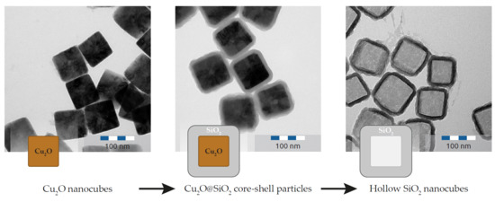
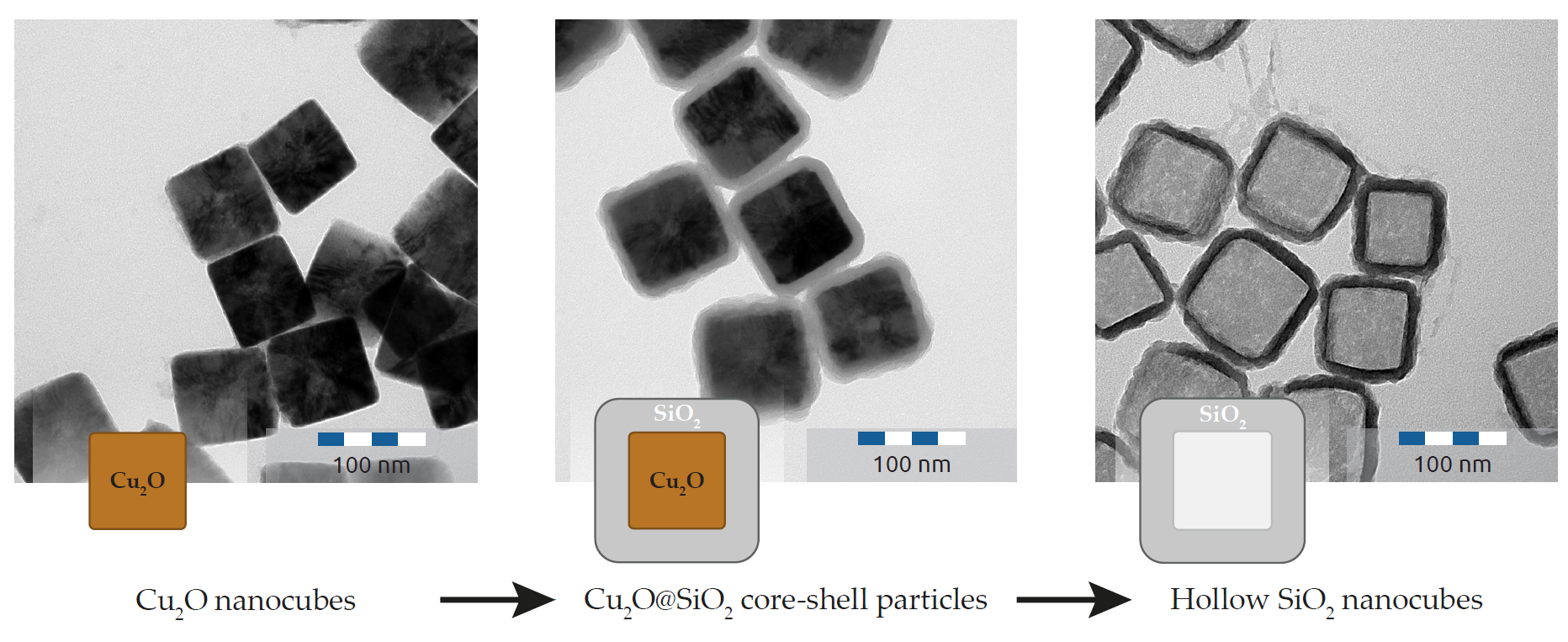
:We present a preparation method for hollow silica nanocubes with tuneable size and shape in the range required for light scattering studies. Cuprous oxide nanocubes are prepared by a water-assisted polyol method. By adjusting the water content, the size of the nanocubes can be tuned in the range of 40–120 nm. These cubes function as a shape template in the subsequent coating with Stöber silica, resulting in core-shell nanocubes. Dissolving the core with nitric acid results in hollow silica nanocubes with sizes ranging from 80–120 nm and cubicity shape parameters between 3 and 6.5.
1. Introduction
At the atomic scale, particle assembly is mainly driven by electron orbital configurations, whereas at the colloidal scale, particle shape is a dominant factor for structures that form by self-assembly [1]. For colloidal spheres, the particle interactions and resulting phase behaviour have been extensively dealt with, in theory and simulations, and are confirmed experimentally [2]. In contrast, for colloidal superball particles, experimental studies on the phase behaviour are limited [3,4,5]. Theoretical work and simulations on concentrated dispersions predict a solid cubic phase and a solid distorted cubic Λ1 phase, depending on the shape parameter of superballs [6,7]. These phases have been observed for micron sized haematite superballs that assemble by external forces such as depletion and gravity [3,4]. The synthesis of these haematite cubes yields cubic particles with a size ranging between 0.5–1.5 μm. Smaller particles synthesized via this route lose their cubic shape [8].
Our is goal is to develop a system of silica cubes which is not dominated by gravity and which is suitable for static and dynamic light scattering experiments [9], for this purpose cubic particles not exceeding a size of approximately 200 nm are required. Larger particles, it should be noted, have a complicated angular scattering intensity profile that hampers the determination of structure factors; particles below 200 nm mainly scatter in the Guinier region, which allows for accurate measurements of structure factors, as demonstrated by the authors of [9]. The preparation of hollow silica cubes has been reported both with [10,11,12,13] and without [14] template. As of yet, no procedure is available for the preparation of hollow silica nanocubes with tuneable size and shape for sizes smaller than 200 nm. Here we show that cuprous oxide nanocubes are a suitable material to serve as a template for sufficiently small silica nanocubes.
Cuprous oxide (Cu2O) is an interesting material from many points of view. Cu2O has a band gap in the visible spectrum, which makes it a good candidate for photovoltaic applications [15]. Additionally, the electronic structure of Cu2O allows for water splitting applications [16,17] and it has anti-bacterial [18] and gas sensing properties [19]. For self-assembly studies, cuprous oxide is also interesting because it appears in a variety of shapes [20] and can be synthesized at significant high yields [21,22]. In 2002, Gou and Murphy were the first to report the wet synthesis of cuprous oxide nanocubes [23]. They used sodium ascorbate to reduce Cu(II) salts in water, resulting in Cu2O particles with a cubic shape, and a typical size between 200 and 450 nm. Although the procedure is elegant and simple, yields are low, typically in the order of a milligram.
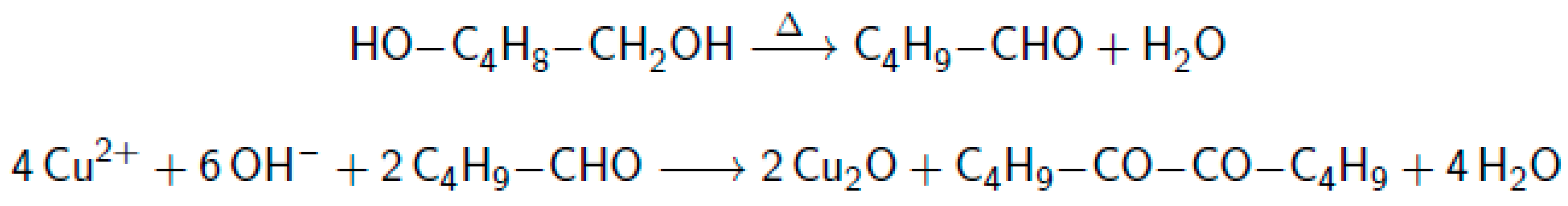
An alternative method to produce metal oxides, is the high-temperature reduction of easily reducible metal salts with a di-alcohol. This method is called the “polyol method” and is employed to produce metal oxides particles with sizes in the 0.5–5 μm range, with various particle shapes [24]. Using the polyol method, Park et al. [21] developed a method to produce nanocubes with a dimension between 50 and 100 nm on a gram scale. No detailed formation mechanism seems to be known for the production of cuprous oxide from Cu(II)acetylacetonoate with 1,5-pentanediol in the presence of polyvinylpyrrolidone. Reports on the polyol reduction [25,26] often mention two steps: first the dehydration of the polyol into an aldehyde, followed by a reduction yielding a diketone. For the reduction of Cu2+ by 1,5-pentenediol, the reaction might proceed as indicated in Figure 1:
The acetylacetonoate (acac) ligand and polyvinylpyrrolidone (PVP), are thought to affect the particle shape, which also is determined by the growth rate of specific crystal facets. These growth rates are influenced by the affinity of acac and PVP with those facets. PVP is known to adsorb on specific crystal facets [27] and it has been demonstrated that increasing the PVP concentration changes the final particle shape [28]. Additionally, upon changing the acac ligand for acetate or hydroxide, sphere and flower-like structures can be obtained [25].
Microporous silica prepared from alkoxysilanes, also termed Stöber silica, is often used by colloid chemists to prepare well defined silica particles ever since it was reported by Stöber and Fink [29]. The formation mechanism and properties of the silica network are well understood [30]. Further, the silica surface can be modified while keeping the matrix intact [31], which makes it possible to disperse silica colloids in a wide range of polar and non-polar solvents. These properties make silica a widely used material with applications in the coating-, food- and medical industries [32,33,34]. Without using a template, amorphous silica nucleates and grows as spheres. Using the PVP assisted coating method [35,36], however, it is possible to deposit silica on a wide range of particle shapes, as demonstrated by Wang et al. [37], who obtained hollow silica cubes, ellipsoids, capsules and peanuts.
To study properties of a stable nanocube fluid, a well-controlled preparation of model particles is required. Here, we present a new method to obtain hollow silica cubes with an average size that can be tuned in the range 80–120 nm. These silica cubes are quite uniform in size and shape, display long-term colloidal stability when stored in ethanol and only slowly settle under gravity on a timescale of weeks.
2. Materials and Methods
2.1. Materials
Copper(II) acetylacetonoate (97%), polyvinylpyrrolidone (molar mass 10 kg/mol), polyvinylpyrrolidone (molar mass 55 kg/mol), tetraethyl orthosilicate (>99.0%) and tetramethylammonium hydroxide (25 wt% in water) were obtained from Sigma-Aldrich, acetone (practical grade) and ethanol (technical grade) were purchased from Interchema. Hydrochloric acid (37%) and Nitric Acid (65%) were acquired from Emsure, 1,5-pentanediol (97%) was obtained from Alfa Aesar and dimethyl sulfoxide (99.7%) was purchased from Acros Organics. All products were used as received. All water used was purified by a Millipore apparatus (18.2 Ω∙cm at 25 °C).
2.2. Synthesis of Cuprous Oxide Nanocubes
A typical preparation of Cu2O (cuprous oxide) nanocubes, adapted from Park et al. [21] was as follows: PVP-55 (polyvinylpyrrolidone (Mw 55 kg/mol), 5.3 g) was dissolved in pentanediol (44.8 g) and the solution was transferred to a three-neck round-bottom flask. The solution was heated to 100 °C and vacuum was applied until no more gas production was visible. Cu(acac)2 (Copper(II) acetylacetonate, 1.04 g) was mixed with pentanediol (15.0 g) by vigorously shaking and agitating by sonication. The Cu(acac)2 and pentanediol mixture was then transferred to a dripping funnel, after which water (0.15 mL) was added. The dripping funnel was then flushed with nitrogen four times. The PVP-55 solution was heated to 195 °C with an oil bath that was kept at a temperature between 215 °C–220 °C, after which the Cu(acac)2 water mixture was added through the dripping funnel. After 20 min, heating was discontinued and the mixture was allowed to cool down to room temperature. The particles were collected by adding acetone (150 mL) and centrifuging the particles at 3000 g for 2 h. The particles were then washed with ethanol by centrifugation and finally redispersed in ethanol (20 mL).
2.3. Silica Coated Nanocubes
Next, Cu2O@SiO2 (Cu2O nanocubes coated with Stöber silica) were prepared as follows [36]: To a two-neck round-bottom flask, ethanol (95 mL) and Cu2O nanocubes (5 mL, 30 mg dry weight, synthesized as described in Section 2.2), water (16.5 mL) and TMAH (tetramethylammonium hydroxide, 2.5 mL, 1 wt% aqueous solution) were added. TEOS (tetraethyl orthosilicate, 30 μL) was dissolved in ethanol (10 mL) and added to the particle dispersion with a Gylson peristaltic pump (tubing diameter: 1.0 mm) over 45 min. After adding TEOS, PVP-40 (2.5 g in 25 mL ethanol) was added to the mixture. The solution was stirred and sonicated for 2 h, followed by stirring for at least 12 h. The particles were then washed with ethanol by centrifugation and finally redispersed in ethanol (10 mL).
2.4. Dissolution of the Cuprous Oxide Core
To obtain hollow silica cubes, the Cu2O@SiO2 particles (synthesis described in Section 2.3) were redispersed in water (30 mL), after which hydrochloric acid (0.5 mL, 6 M) and nitric acid (0.5 mL, 6 M) were added. The acidic dispersion was allowed to react for at least 1 h to ensure dissolution of the cuprous oxide cores. The particles were then centrifuged and redispersed in water (5 mL). The aqueous dispersion was transferred to a round-bottom flask and concentrated nitric acid (10 mL) was added. This acidic dispersion was heated to 95 °C for 3 h. The particles were collected, washed extensively with ethanol and finally redispersed in ethanol (20 mL).
2.5. Transmission Electron Microscopy Sample Preparation
To 0.5 mL water, a drop of particle dispersion was added. A single drop of this diluted dispersion was then deposited on a carbon coated copper grid and dried under a heating lamp for 1 h.
2.6. Infrared Spectroscopy Sample Preparation
To 250 mg KBr, an ethanolic dispersion containing approximately 1 mg analyte was added. This mixture was placed in an oven and heated at 80 °C overnight. The dry analyte was then taken out of the oven and immediately pressed into a pellet and analysed.
2.7. Elemental Analysis
Elemental analysis on the samples was carried out by Geolab at Utrecht University.
3. Results and Discussion
3.1. Synthesis Method
The synthesis of cuprous oxide nanoparticles from Park et al. [21] appeared to be difficult to reproduce, which prompted us to change the method described in their paper in a number of ways. First and foremost, it is important to mention that copper(II)acetylacetonoate does not dissolve completely in 1,5-pentanediol. Therefore, we mixed the precursor with pentanediol, followed by sonication and vortexing, to ensure a homogeneous dispersion. Additionally we found, that the synthesis temperature used in [21] was too high to achieve successful synthesis of cubic particles. Employing the reported temperature of 240 °C, we repeatedly obtained spherical particles. Performing the synthesis in an oil bath, not exceeding a temperature of 225 °C and a reaction mixture not exceeding a temperature of 205 °C, yielded most satisfactory results in our set-up. During most syntheses, the oil bath temperature was kept between 215 °C–220 °C and the temperature of the reaction mixture between 185 °C–200 °C. Last but not least, we assessed that the purity of the copper(II)acetylacetonoate significantly influences the products obtained. Performing the synthesis with a 99.99% Cu(II)(acac)2 salt resulted in low yields and smaller particles (40 vs. 66 nm). From infrared spectroscopy (IR) analysis of the copper salt we surmise that an impurity in the copper salt causes this difference. No conclusive data on the nature of the impurity has been obtained yet.
3.2. Particle Size
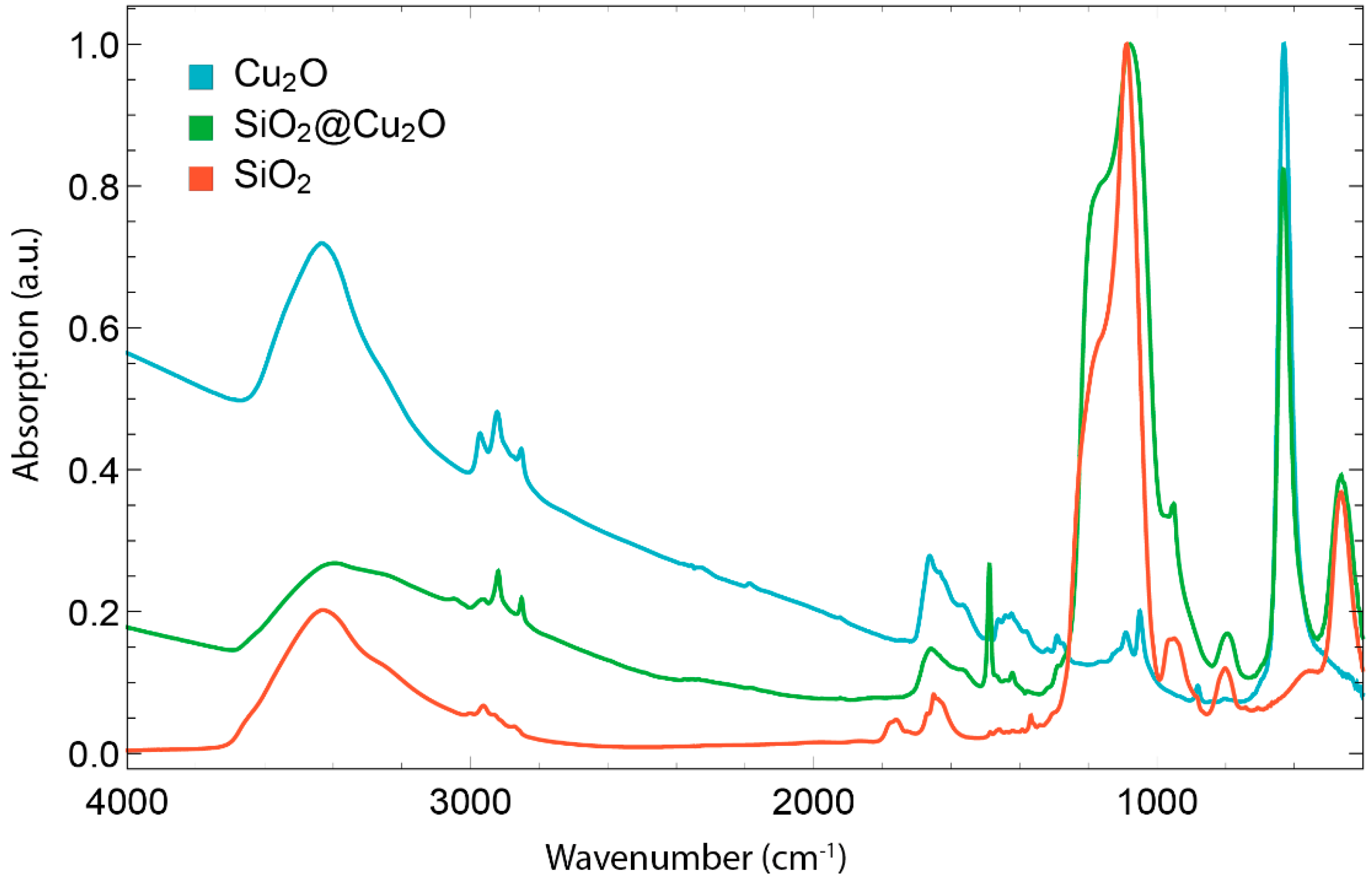
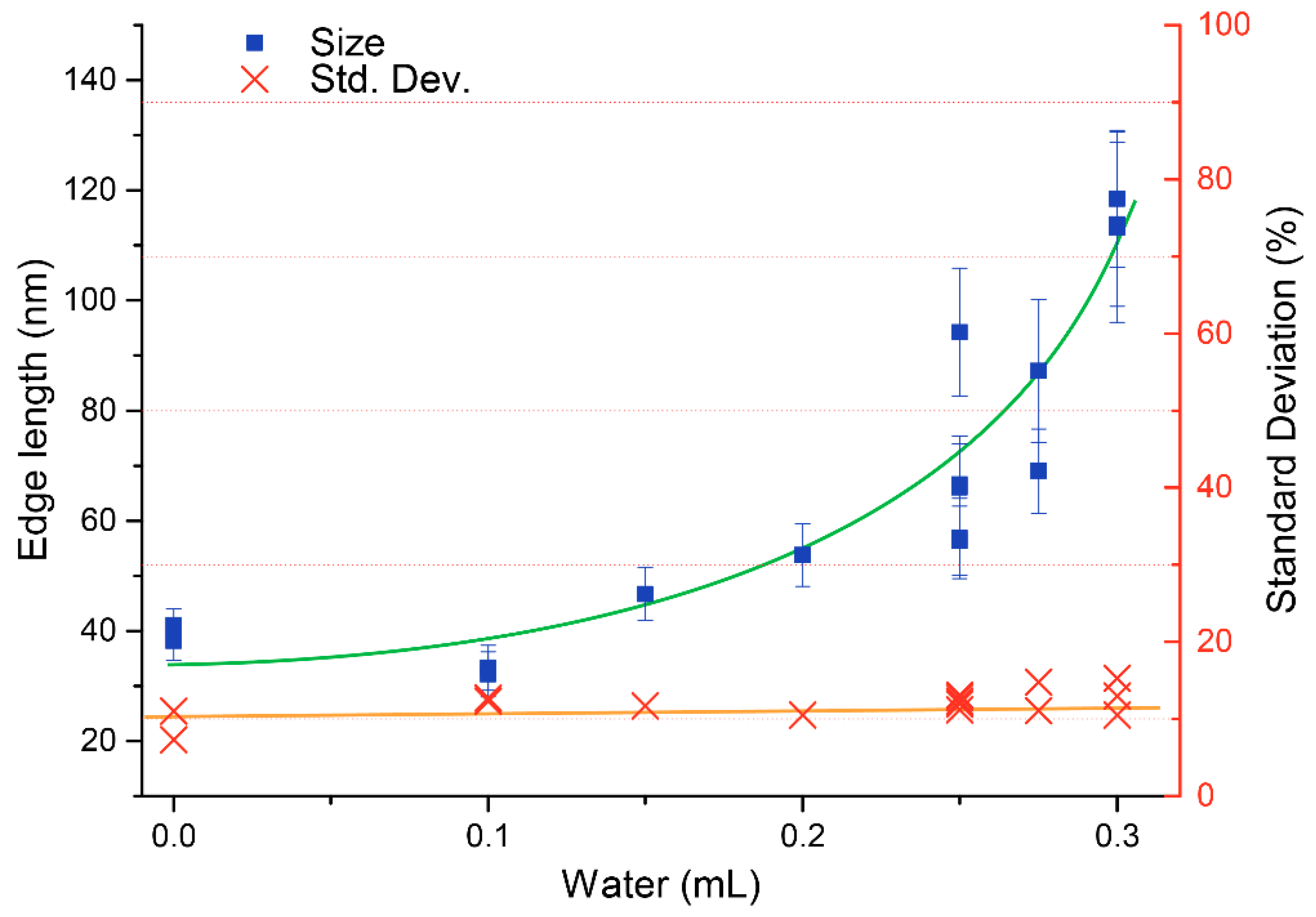
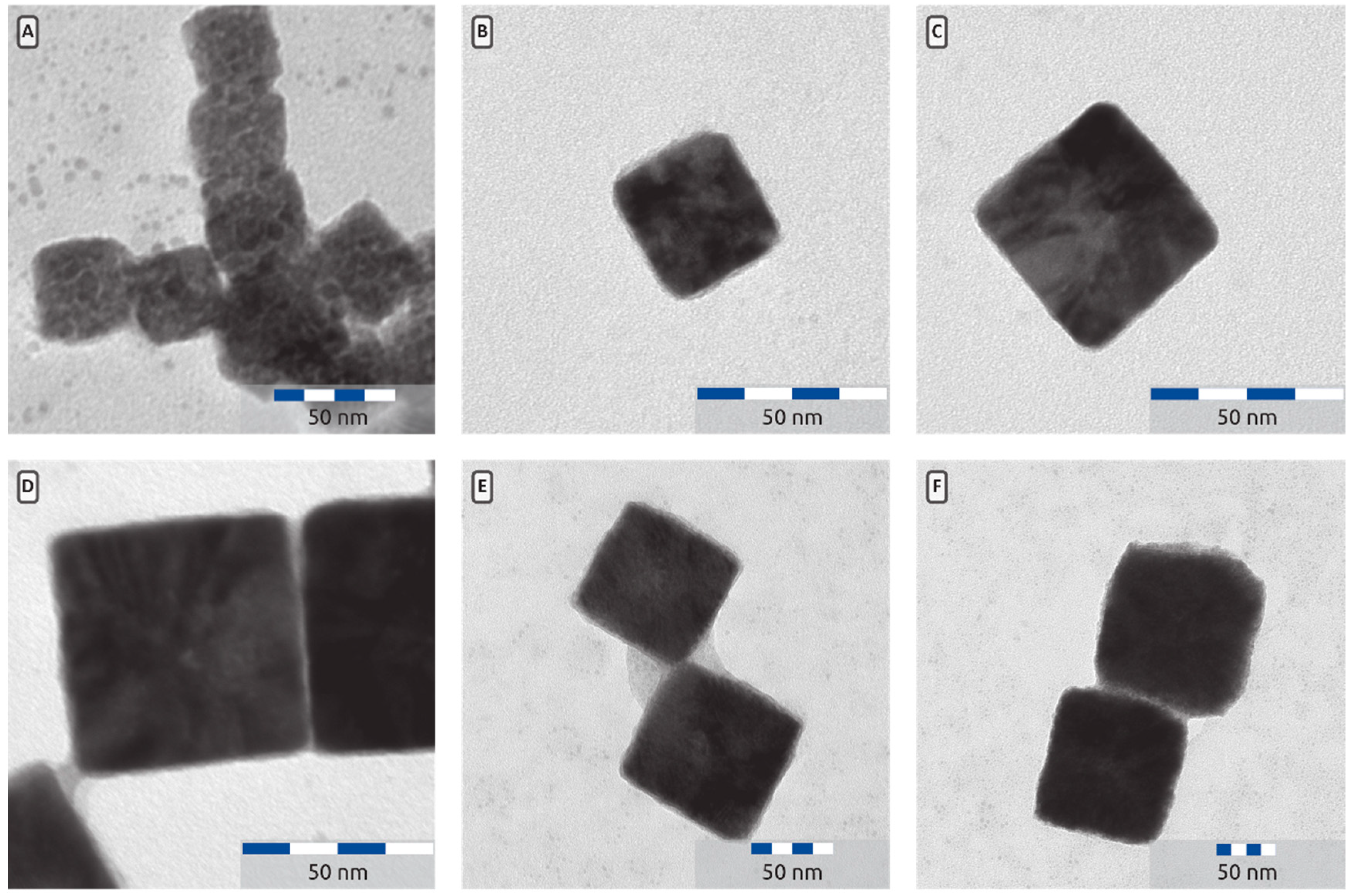
The cuprous oxide nanocubes were analysed by transmission electron microscopy (TEM). In Figure 2 a typical TEM picture is presented. The particle size and its standard deviation was determined by measuring the edge lengths of more than 100 particles. The TEM pictures (Figure 2 clearly showthat the particles have a cubic shape with sharp edges. The nanocube edges seem to contain some lower contrast material; this might be PVP, still adsorbed on the particles. The presence of PVP is also visible in the IR spectrum of Cu2O nanocubes (Figure 3), where absorption between 1200 cm−1 and 1500 cm−1 is characteristic for PVP. In Figure 4 an overview is presented of the different particles synthesized. In this study, the amount of water added to the mixture was varied between 0 and 0.3 mL (0–16.7 mmol) while the amount of Cu(acac)2 was kept constant (4 mmol). From Figure 4 it is clear that the average particle size increases as more water is added during the synthesis. At a low volume of added water, the Cu2O cubes have an average size around 35 nm. When more than 8 mmol of water is added (0.15 mL or more) the particle size starts to increase. This increase persists up to 120 nm, when 0.3 mL water is added during the synthesis. The polydispersity of the particles varies between 10.5 and 15.3% with respect to the average particle size and seems to be independent of the particle size. The TEM images show that a shift in particle shape is present when different amounts of water are added. For the particles with no added water (Figure 5A,B), nucleation takes place, but the final particles look more rounded and the presence of spherical features suggests the particle was unable to develop its cubic shape. At intermediate water content, well-defined cubes are obtained (Figure 2A and Figure 5C,D). When higher water contents are used (Figure 5F) the cubes become more rounded and defects in the particles become visible. Both the increase in size and particle morphology indicate that the amount of water in the system greatly influences the particle growth, as was also discussed by Dong et al. [16]. From infrared spectroscopy (IR) data (Figure 3) it is clear that the spectra are a combination of the characteristic Cu2O peak (610 cm−1) and the gradual increasing absorbance at higher wavenumbers, which is also characteristic for Cu2O. The typical yield for the cuprous oxide nanocubes was about 200 mg of solid content, determined by drying a known volume of dispersion and weighing the dry residue. The yield, however, varied significantly from one synthesis to the other. The total yield can be increased five-fold by using five times as much reagents in the synthesis described in Section 3.2. However, the particle size increases upon this upscaling. Adding water does not seem to increase the particle size significantly further. Two reasons for this effect can be considered. First, a different temperature profile during the synthesis is present, since heat transfer in a larger reaction vessel is different compared to that in the small vessel. Further there is probably more water present during the upscaled synthesis. Hence, upscaling this synthesis should be carried out with care.
3.3. Silica Coating and Hollow Silica Nanocubes
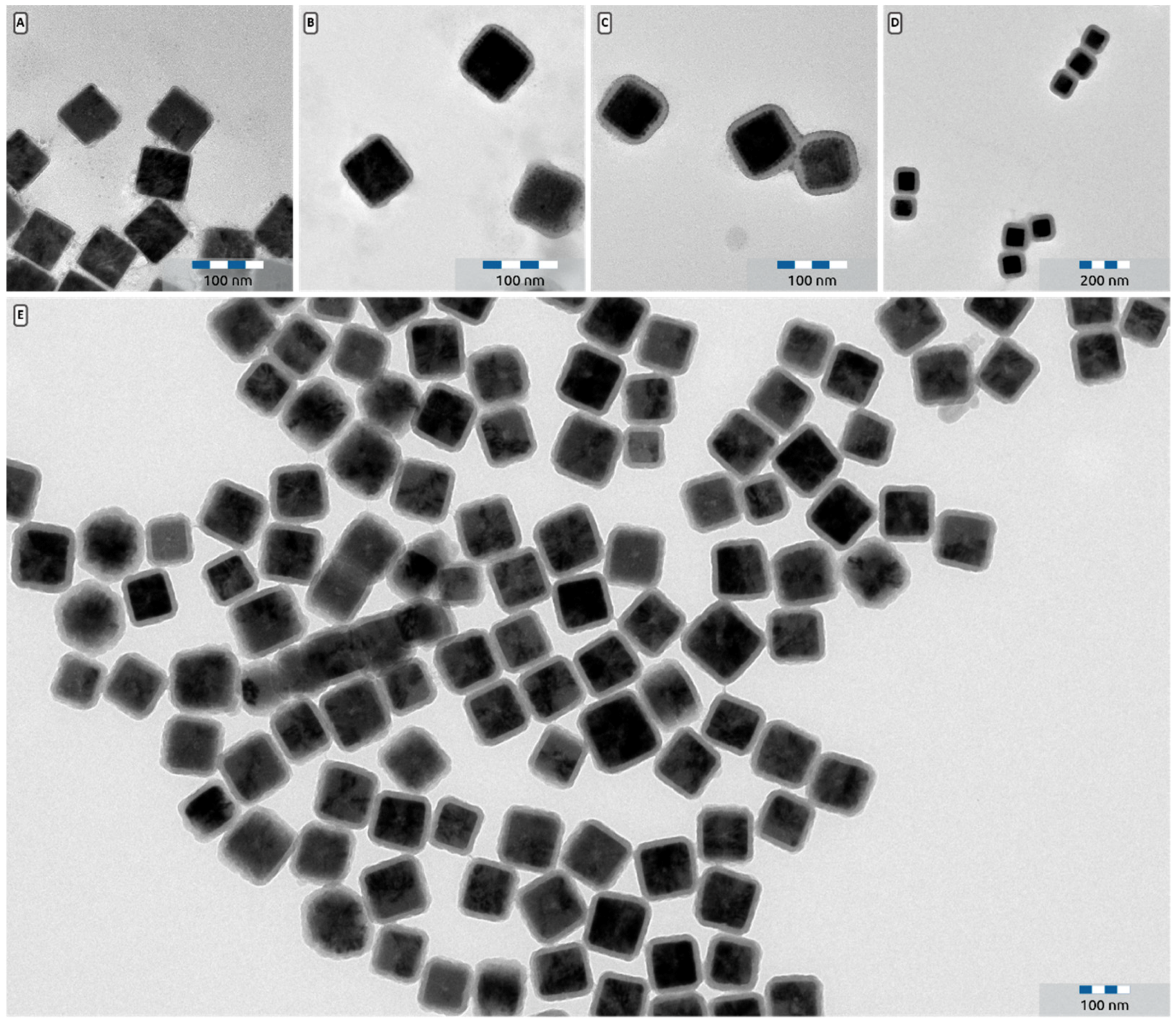
The successful synthesis of silica coated rounded cubes was confirmed by electron microscopy: by using a Stöber silica synthesis, a uniform silica shell can be grown around the Cu2O nanocubes. The characteristic Si-O peak around 1100 cm−1 in the IR spectra confirms that the observed shell is silica (Figure 3). It can be seen on the TEM images that the silica layer forms a homogenous shell around the cubic Cu2O particle. The clustered particles in Figure 6C,D probably are a result from the TEM sample preparation and the reaction of silica when exposed to the electron beam. Only a small fraction of the particles is clustered (Figure 5E) and preliminary light scattering experiments indicate that no significant amount of large aggregates is present in dispersions of core-shell particles. The presence of the silica shell results in slightly more rounded cubes compared to the original particles, but the cubic shape is still pronounced. The thickness of the silica shell can be controlled by varying the amount of TEOS added to the particles (See Figure S2). The particles depicted in Figure 2 were used as a template, and were coated with silica shells of 6 nm (Figure 6A), 9 nm (Figure 6B), 13 nm (Figure 6C) and 21 nm (Figure 6D).
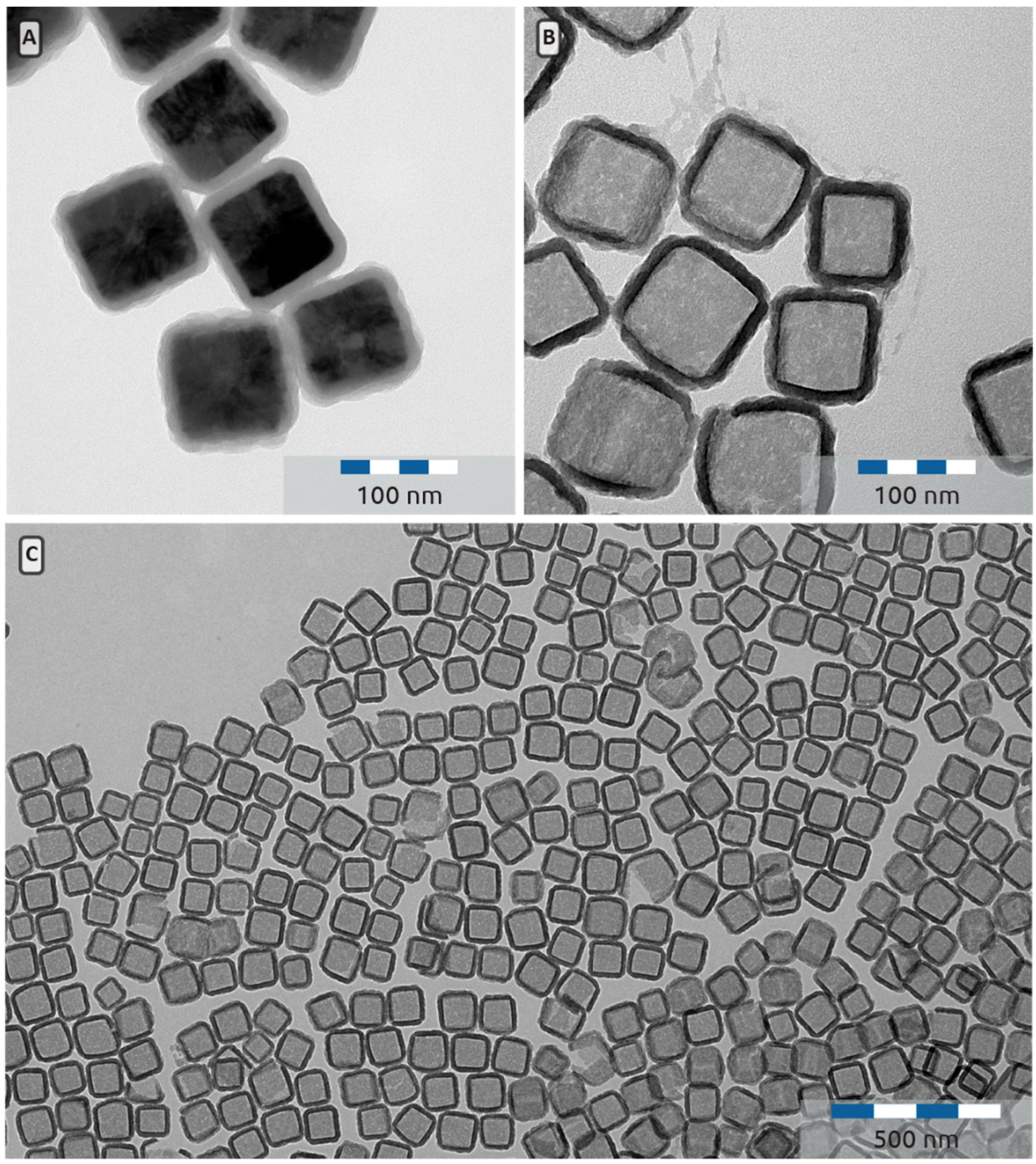
Most of the cuprous oxide core can be easily dissolved by dispersing the particles in an aqueous 0.6 M HCl/HNO3 solution. Immediately a colour change is visible from an orange-brown dispersion to a white dispersion with a slightly red tone. Since the dispersion is not completely white, some copper species may still be present in the hollow silica cubes. Boiling in concentrated nitric acid eventually yields a completely white dispersion. Further, after treatment with concentrated HNO3 it is visible that the Cu2O core is completely dissolved while preserving the cubic shape (Figure 7B). Moreover, the absence of the Cu2O specific absorption at 630 cm−1 in the infrared spectrum of the hollow silica nanocubes also confirms the complete dissolution of the Cu2O core. This is supported by elemental analysis, which indicates a minute residue of 40 ppm (gram/gram) copper is present in the hollow silica nanocubes.
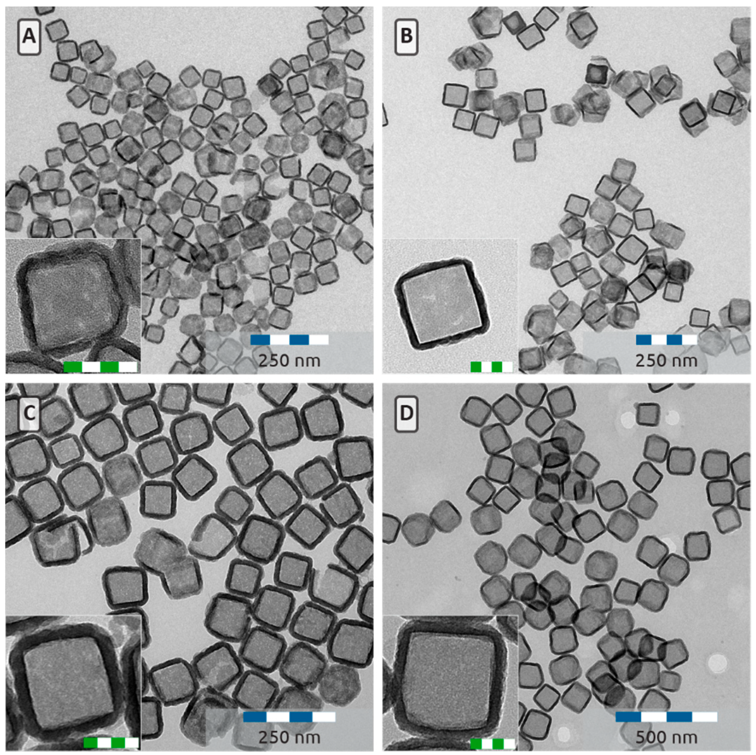
TEM micrographs show that after treatment with concentrated nitric acid, the hollow silica nanoparticles are still cubic in shape (Figure 7), enabling the preparation of hollow silica nanocubes with sizes ranging between 75 and 150 nm (Figure 8). Most of the particles are still intact after TEM sample preparation and a 5 nm shell is sufficient for the particles to maintain their cubic shape under TEM conditions(Figure 9).The collapse of thin silica shells upon drying is also reported by Castillo et al. [36], who showed that drying the particles at a slower rate, for example by freeze-drying, would prevent the particles from collapsing. This suggests that the majority of the particles are dispersed as intact hollow silica cubes.
3.4. Particle shape
The cubicity of the particles is determined and expressed here by the shape parameter m, which is a parameter in the equation of a superball or supercircle. The equation of a supercircle is given by:
where a is the edge-length of the supercircle. When , the supercircle is a perfect circle. When , the shape is a perfect square. For intermediate m values, equation 1 describes a square with rounded corners and concave edges. To determine the m-factor of a particle from micrographs, two options were considered. The first is to fit the equation for a supercircle to the outline of a particle with a MATLAB script [4]. This is a very precise method but requires high resolution pictures and particles whose outline closely resemble a superball. A different way to measure the shape parameter of a rounded square, is by measuring the aspect ratio (AR) between the edge-length (a) and the diagonal (b). By using the following relationship:
which enables to derive m by hand, so no script is required and the method is still suitable for particles that deviate from a superball. Hence, m follows from:
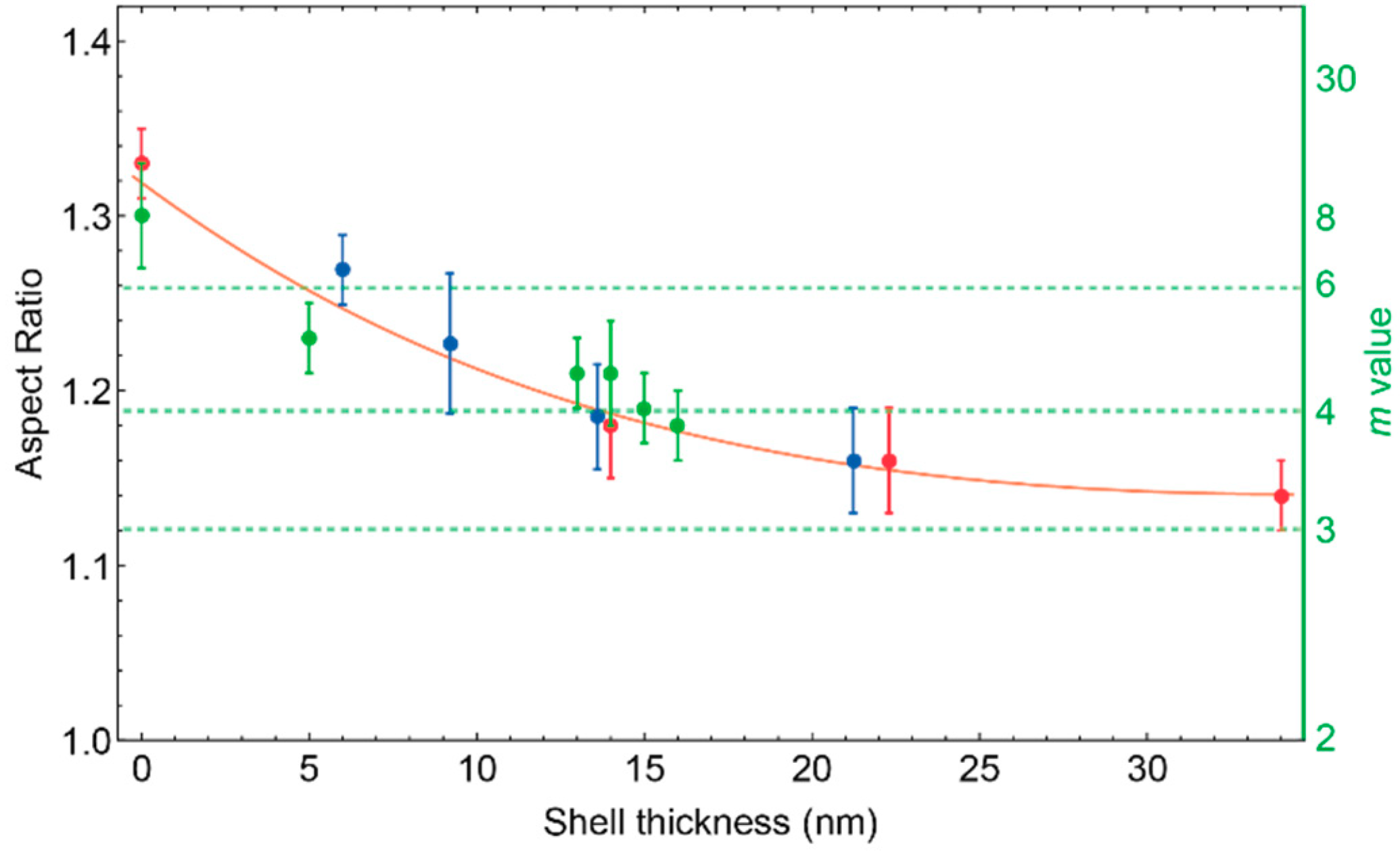
The aspect ratio can be measured from TEM pictures by drawing ellipses to determine the particle diameter and edge length (Figure S1) for various particles. With this method, an average m-value was calculated. No correlation was found between the size of the cuprous oxide nanoparticles and the m-value. Coating the particles with a silica shell enables us to control the shape of the particle. In Figure 10 the measured aspect ratios are shown before and after coating with silica. The data in Figure 10 illustrates that increasing the silica shell lowers the aspect ratio. With a silica shell between 5–35 nm thick, particles can be prepared with m-values between 6.5 and 3.2.
3.5. Colloidal Stability
For static and dynamic light scattering experiments, it is important that particle dispersions are colloidally stable [31], e.g., the particles do not aggregate and sediment slowly. We find that the hollow silica cubes sediment slowly under gravity; it takes weeks before a sedimentation profile develops and months before the particles completely sediment to the bottom of a 20 mL vial. When dispersed in ethanol, no particle aggregation is visible. Additionally, when the particles sediment, as mediated by centrifugation, the sediment is easily redispersed by vortexing and sonication. This confirms the colloidal stability of the hollow silica cubes, which makes them promising model particles for light scattering studies.
4. Conclusions
Cuprous oxide nanoparticles can be obtained reproducible with sizes in the range of 40 to 120 nm. These particles are highly cubic with m values up to 12, which is significantly above the maximum (m = 4) for micron sized heamatite cubes reported earlier. These particles can be coated with silica to obtain core shell Cu2O@SiO2 particles. The resulting shell thickness can be controlled by varying the amount of TEOS precursor and the final shell thickness varies between 5 nm and 35 nm. The m value of the particles can be controlled between 6.5 and 3.2. The cuprous oxide core can be fully dissolved by treatment with heated nitric acid, resulting in hollow silica nanoparticles with size ranges between 75 and 150 nm. The uniform silica cubes can be dispersed in ethanol and exhibit long term colloidal stability. The fact that the turbidity of the ethanolic cube dispersion is fairly low makes them suitable model particles for light scattering studies on cubic colloids. The outcome of the Cu2O synthesis appears to be very sensitive to conditions, such as the detailed temperature profile and the reagents used for the synthesis.
Supplementary Materials
The following are available online at https://www.mdpi.com/2504-5377/2/4/44/s1. Figure S1: Illustration of the m-value determination: visualization of the method used to determine the aspect ratio of the cube. Figure S2: The thickness of the silica shell of Cu2O@SiO2 particles plotted against the amount of TEOS added with respect to the dry weight of the particles (gram/gram).
Author Contributions
Conceptualization, F.D, R.T and A.P.P.; Methodology, F.D.; Validation, F.D., R.T. and A.P.P.; Formal Analysis, F.D.; Investigation, F.D.; Data Curation, F.D.; Writing, Original Draft Preparation, F.D.; Writing, Review and Editing, R.T. and A.P.P.; Visualization, F.D.; Supervision, R.T and A.P.P.; Project Administration, A.P.P.; Funding Acquisition, R.T and A.P.P., please turn to the credit taxonomy for the term explanation.
Funding
This research was funded by NWO-TTW project number 14210.
Acknowledgments
The “Colloidal Mosaics” user committee is thanked for helpful discussions.
Conflicts of Interest
The authors declare no conflict of interest.
References
- Damasceno, P.F.; Engel, M.; Glotzer, S.C. Predictive self-assembly of polyhedra into complex structures. Science 2012, 337, 453–457. [Google Scholar] [CrossRef] [PubMed]
- Vrij, A.; Tuinier, R. Structure of Concentrated Colloidal Dispersions. In Fundamentals of Interface and Colloids Science Volume IV Particulate Colloids; Lyklema, J., Ed.; Elsevier B.V.: Amsterdam, The Netherlands, 2005; p. 692. ISBN 9780124605299. [Google Scholar]
- Meijer, J.M.; Pal, A.; Ouhajji, S.; Lekkerkerker, H.N.W.; Philipse, A.P.; Petukhov, A.V. Observation of solid-solid transitions in 3D crystals of colloidal superballs. Nat. Commun. 2017, 8, 1–8. [Google Scholar] [CrossRef] [PubMed]
- Rossi, L.; Soni, V.; Ashton, D.J.; Pine, D.J.; Philipse, A.P.; Chaikin, P.M.; Dijkstra, M.; Sacanna, S.; Irvine, W.T.M. Shape-sensitive crystallization in colloidal superball fluids. Proc. Natl. Acad. Sci. USA 2015, 112, 5286–5290. [Google Scholar] [CrossRef] [PubMed] [Green Version]
- Zhang, Y.; Lu, F.; Van Der Lelie, D.; Gang, O. Continuous phase transformation in nanocube assemblies. Phys. Rev. Lett. 2011, 107, 2–5. [Google Scholar] [CrossRef] [PubMed]
- Batten, R.D.; Stillinger, F.H.; Torquato, S. Phase behavior of colloidal superballs: Shape interpolation from spheres to cubes. Phys. Rev. E 2010, 81, 1–13. [Google Scholar] [CrossRef] [PubMed]
- Dijkstra, M. Entropy-Driven Phase Transitions in Colloids: From spheres to anisotropic particles. In Advances in Chemical Physics; Rice, S.A., Dinner, A.R., Eds.; Wiley Blackwell: Hoboken, NJ, USA, 2014; Volume 156, pp. 35–71. ISBN 9781118949702. [Google Scholar]
- Castillo, S.I.R. Cubic colloids: Synthesis, functionalization and applications. Ph.D. Thesis, Utrecht University, Utrecht, The Netherlands, January 2015. [Google Scholar]
- Philipse, A.P.; Vrij, A. Determination of static and dynamic interactions between monodisperse, charged silica spheres in an optically matching, organic solvent. J. Chem. Phys. 1988, 88, 6459–6470. [Google Scholar] [CrossRef]
- Yang, H.; Min, Y.; Kim, Y.J.; Jeong, U. Preparation of Cu2O@SiO2 particles and their evolution to hollow SiO2 particles. Colloids Surfaces A Physicochem. Eng. Asp. 2013, 420, 30–36. [Google Scholar] [CrossRef]
- Wang, Z.; Snyder, M.A.; Fan, W.; Tsapatsis, M. Hollow cubic silica shells and assembled porous coatings. Scr. Mater. 2010, 62, 504–507. [Google Scholar] [CrossRef]
- Zhang, M.; Fang, K.; Lin, M.; Hou, B.; Zhong, L.; Zhu, Y.; Wei, W.; Sun, Y. Controlled fabrication of iron oxide/mesoporous silica core-shell nanostructures. J. Phys. Chem. C 2013, 117, 21529–21538. [Google Scholar] [CrossRef]
- Han, Y.S.; Jeong, G.Y.; Lee, S.Y.; Moon, K.H.; Kim, H.K. Synthesis of cubic type hollow silica particles. Mater. Lett. 2009, 63, 1278–1280. [Google Scholar] [CrossRef]
- Kong, L.; Liu, X.; Bian, X.; Wang, C. Silica nanocubes with a hierarchically porous structure. RSC Adv. 2012, 2, 2887–2894. [Google Scholar] [CrossRef]
- Musa, A.O.; Akomolafe, T.; Carter, M.J. Production of cuprous oxide, a solar cell material, by thermal oxidation and a study of its physical and electrical properties. Sol. Energy Mater. Sol. Cells 1998, 51, 305–316. [Google Scholar] [CrossRef]
- Hara, M.; Kondo, T.; Komoda, M.; Ikeda, S.; Kondo, J.N.; Domen, K.; Hara, M.; Shinohara, K.; Tanaka, A. Cu2O as a photocatalyst for overall water splitting under visible light irradiation. Chem. Commun. 1998, 2, 357–358. [Google Scholar] [CrossRef]
- Paracchino, A.; Laporte, V.; Sivula, K.; Grätzel, M.; Thimsen, E. Highly active oxide photocathode for photoelectrochemical water reduction. Nat. Mater. 2011, 10, 456–461. [Google Scholar] [CrossRef] [PubMed]
- Pang, H.; Gao, F.; Lu, Q. Morphology effect on antibacterial activity of cuprous oxide. Chem. Commun. 2009, 1076. [Google Scholar] [CrossRef] [PubMed]
- Shishiyanu, S.T.; Shishiyanu, T.S.; Lupan, O.I. Novel NO2 gas sensor based on cuprous oxide thin films. Sens. Actuators B Chem. 2006, 113, 468–476. [Google Scholar] [CrossRef]
- Huang, W.C.; Lyu, L.M.; Yang, Y.C.; Huang, M.H. Synthesis of Cu2O nanocrystals from cubic to rhombic dodecahedral structures and their comparative photocatalytic activity. J. Am. Chem. Soc. 2012, 134, 1261–1267. [Google Scholar] [CrossRef] [PubMed]
- Park, J.C.; Kim, J.; Kwon, H.; Song, H. Gram-scale synthesis of Cu2O nanocubes and subsequent oxidation to CuO hollow nanostructures for lithium-ion battery anode materials. Adv. Mater. 2009, 21, 803–807. [Google Scholar] [CrossRef]
- Carbó-Argibay, E.; Bao, X.Q.; Rodríguez-Abreu, C.; Fátima Cerqueira, M.; Petrovykh, D.Y.; Liu, L.; Kolen’ko, Y.V. Up-scaling the synthesis of Cu2O submicron particles with controlled morphologies for solar H2 evolution from water. J. Colloid Interface Sci. 2015, 456, 219–227. [Google Scholar] [CrossRef] [PubMed]
- Gou, L.; Murphy, C.J. Solution-phase synthesis of Cu2O nanocubes. Nano Lett. 2003, 3, 231–234. [Google Scholar] [CrossRef]
- Dong, H.; Chen, Y.-C.; Feldmann, C. Polyol synthesis of nanoparticles: status and options regarding metals, oxides, chalcogenides, and non-metal elements. Green Chem. 2015, 17, 4107–4132. [Google Scholar] [CrossRef]
- Chen, L.; Zhang, Y.; Zhu, P.; Zhou, F.; Zeng, W.; Lu, D.D.; Sun, R.; Wong, C. Copper Salts Mediated Morphological Transformation of Cu2O from Cubes to Hierarchical Flower-like or Microspheres and Their Supercapacitors Performances. Sci. Rep. 2015, 5, 9672. [Google Scholar] [CrossRef] [PubMed]
- Fievet, F.; Lagier, J.P.; Blin, B.; Beaudoin, B.; Figlarz, M. Homogeneous and heterogeneous nucleations in the polyol process for the preparation of micron and submicron size metal particles. Solid State Ionics 1989, 32–33, 198–205. [Google Scholar] [CrossRef]
- Tao, A.; Sinsermsuksakul, P.; Yang, P. Polyhedral silver nanocrystals with distinct scattering signatures. Angew. Chemie - Int. Ed. 2006, 45, 4597–4601. [Google Scholar] [CrossRef] [PubMed]
- Sui, Y.; Fu, W.; Yang, H.; Zeng, Y.; Zhang, Y.; Zhao, Q.; Li, Y.; Zhou, X.; Leng, Y.; Li, M.; et al. Low Temperature Synthesis of Cu2O Crystals: Shape Evolution and Growth Mechanism. Cryst. Growth Des. 2010, 10, 99–108. [Google Scholar] [CrossRef]
- Stober, W.; Fink, A. Controlled Growth of Monodispersed Silica Spheres in the Micron Size Range. J. Colloid Interface Sci. 1968, 26, 62–69. [Google Scholar] [CrossRef]
- van Blaaderen, A.; Kentgens, A.P.M. Particle morphology and chemical microstructure of colloidal silica spheres made from alkoxysilanes. J. Non. Cryst. Solids 1992, 149, 161–178. [Google Scholar] [CrossRef]
- Philipse, A.P.; Vrij, A. Preparation and properties of nonaqueous model dispersions of chemically modified, charged silica spheres. J. Colloid Interface Sci. 1989, 128, 121–136. [Google Scholar] [CrossRef]
- Dickinson, E. Food emulsions and foams: Stabilization by particles. Curr. Opin. Colloid Interface Sci. 2010, 15, 40–49. [Google Scholar] [CrossRef]
- Erathodiyil, N.; Ying, J.Y. Functionalization of inorganic nanoparticles for bioimaging applications. Acc. Chem. Res. 2011, 44, 925–935. [Google Scholar] [CrossRef] [PubMed]
- Buskens, P.; Arfsten, N.; Habets, R.; Langermans, H.; Overbeek, A.; Scheerder, J.; Thies, J.; Viets, N. Innovation at DSM: State of the Art Single Layer Anti-Reflective Coatings for Solar Cell Cover. Glass Performance Days, 17 June 2010; 505–507. [Google Scholar]
- Graf, C.; Vossen, D.L.J.; Imhof, A.; Van Blaaderen, A. A general method to coat colloidal particles with silica. Langmuir 2003, 19, 6693–6700. [Google Scholar] [CrossRef]
- Castillo, S.I.R.; Ouhajji, S.; Fokker, S.; Erné, B.H.; Schneijdenberg, C.T.W.M.; Thies-Weesie, D.M.E.; Philipse, A.P. Silica cubes with tunable coating thickness and porosity: From hematite filled silica boxes to hollow silica bubbles. Microporous Mesoporous Mater. 2014, 195, 75–86. [Google Scholar] [CrossRef]
- Wang, Y.; Su, X.; Ding, P.; Lu, S.; Yu, H. Shape-controlled synthesis of hollow silica colloids. Langmuir 2013, 29, 11575–11581. [Google Scholar] [CrossRef] [PubMed]
Figure 1.
Proposed reaction scheme for the polyol reduction of Cu(acac)2 to Cu2O.

Figure 2.
(A) Transmission electron microscopy (TEM) image of Cu2O prepared according to Section 2.2 with 0.25 mL water and an edge length of 66 ± 8 nm. (B) Typical overview picture of the Cu2O particles (depicted at small length scales in (A). Clearly cubic particles with sharp edges are obtained.
Figure 2.
(A) Transmission electron microscopy (TEM) image of Cu2O prepared according to Section 2.2 with 0.25 mL water and an edge length of 66 ± 8 nm. (B) Typical overview picture of the Cu2O particles (depicted at small length scales in (A). Clearly cubic particles with sharp edges are obtained.

Figure 3.
Infrared spectra of Cu2O cubes (Cyan), Cu2O@SiO2 core shell particles (green) and hollow SiO2 nanocubes (orange). All spectra are normalised such that the highest peak has an absorption of 1.
Figure 3.
Infrared spectra of Cu2O cubes (Cyan), Cu2O@SiO2 core shell particles (green) and hollow SiO2 nanocubes (orange). All spectra are normalised such that the highest peak has an absorption of 1.

Figure 4.
Size of Cu2O nanocubes synthesized with varying amounts of added water. The graph shows that the final particles size increases with increasing amount of added water. The green and orange curves are to guide the eye.
Figure 4.
Size of Cu2O nanocubes synthesized with varying amounts of added water. The graph shows that the final particles size increases with increasing amount of added water. The green and orange curves are to guide the eye.

Figure 5.
(A) Cu2O particles prepared with no added water with an edge length a = 41 ± 3 nm. (B) Cu2O particles prepared with 0.1 mL water and a = 33 ± 4 nm. (C) Cu2O particles prepared with 0.15 mL water and a = 48 ± 5 nm. (D) Cu2O particles prepared with 0.2 mL water and a = 54 ± 6 nm. (E): Close up of Cu2O cubes prepared with 0.275 mL water and a = 87 ± 13 nm. The low contrast material between the particles is probably PVP. (F) Overview picture of Cu2O prepared with 0.3 mL water and a = 118 ± 13 nm.

Figure 6.
(A) TEM picture of Cu2O@SiO2 core-shell particles with a 6 nm shell. (B) TEM picture of Cu2O@SiO2 core-shell particles with a 9 nm shell. (C): TEM picture of Cu2O@SiO2 core-shell particles with a 13 nm shell. (D) TEM picture of Cu2O@SiO2 core shell particles with a 21 nm shell. (E) Low magnification TEM image of Cu2O@SiO2 core-shell particles with a 13 nm shell that shows the uniform thickness of the silica shell.

Figure 7.
(A) TEM picture of Cu2O@SiO2 core shell particles with an edge length of 112 ± 10 nm with a 13 nm shell. (B) TEM picture of hollow SiO2 nanocubes obtained after treating the particles in depicted in A with concentrated nitric acid. (C) Low magnification TEM image of an assembly of hollow silica nanocubes.

Figure 8.
Hollow silica nanocubes with an edge length of 76 ± 7 nm (A), 96 ± 8 nm (B), 118 ± 11 nm (C) and 150 ± 13 nm (D) Insets are higher magnification micrographs. Scale bars in the insets are 50 nm.
Figure 8.
Hollow silica nanocubes with an edge length of 76 ± 7 nm (A), 96 ± 8 nm (B), 118 ± 11 nm (C) and 150 ± 13 nm (D) Insets are higher magnification micrographs. Scale bars in the insets are 50 nm.

Figure 9.
Hollow silica nanocubes with a silica shell of 5.1 ± 0.6 nm (8-A), 12.6 ± 1.6 nm (8-B) and 16.4 ± 1.9 nm (8-C) thick. Insets are higher magnification micrographs. Scale bars in the insets are 50 nm.
Figure 9.
Hollow silica nanocubes with a silica shell of 5.1 ± 0.6 nm (8-A), 12.6 ± 1.6 nm (8-B) and 16.4 ± 1.9 nm (8-C) thick. Insets are higher magnification micrographs. Scale bars in the insets are 50 nm.

Figure 10.
Influence of the relative shell thickness to the aspect ratio of the particles. The data points on the left (shell thickness 0 nm) are the core particles. On the right Y axis the corresponding m-values are indicated. Dotted lines are drawn for m = 3, m = 4 (highest m value obtained with the heamatite method [4]) and m = 6 (highest m value obtained in this study). The orange curve is to guide the eye.

© 2018 by the authors. Licensee MDPI, Basel, Switzerland. This article is an open access article distributed under the terms and conditions of the Creative Commons Attribution (CC BY) license (http://creativecommons.org/licenses/by/4.0/).
Share and Cite
MDPI and ACS Style
Dekker, F.; Tuinier, R.; Philipse, A.P. Synthesis of Hollow Silica Nanocubes with Tuneable Size and Shape, Suitable for Light Scattering Studies. Colloids Interfaces 2018, 2, 44. https://doi.org/10.3390/colloids2040044
AMA Style
Dekker F, Tuinier R, Philipse AP. Synthesis of Hollow Silica Nanocubes with Tuneable Size and Shape, Suitable for Light Scattering Studies. Colloids and Interfaces. 2018; 2(4):44. https://doi.org/10.3390/colloids2040044
Chicago/Turabian StyleDekker, Frans, Remco Tuinier, and Albert P. Philipse. 2018. "Synthesis of Hollow Silica Nanocubes with Tuneable Size and Shape, Suitable for Light Scattering Studies" Colloids and Interfaces 2, no. 4: 44. https://doi.org/10.3390/colloids2040044