
The Machinability Characteristics of Multidirectional CFRP Composites Using High-Performance Wire EDM Electrodes


1
Machining Research Group, Department of Mechanical Engineering, School of Engineering, University of Birmingham, Edgbaston, Birmingham B15 2TT, UK
2
Production Engineering Department, Faculty of Engineering, Helwan University, Helwan 11795, Egypt
*
Author to whom correspondence should be addressed.
J. Compos. Sci. 2022, 6(6), 159; https://doi.org/10.3390/jcs6060159
Submission received: 15 March 2022
/
Revised: 19 May 2022
/
Accepted: 24 May 2022
/
Published: 27 May 2022
(This article belongs to the Special Issue Carbon Fiber Composites, Volume II)
Abstract
:Due to the abrasive nature of the material, the conventional machining of CFRP composites is typically characterised by high mechanical forces and poor tool life, which can have a detrimental effect on workpiece surface quality, mechanical properties, dimensional accuracy, and, ultimately, functional performance. The present paper details an experimental investigation to assess the feasibility of wire electrical discharge machining (WEDM) as an alternative for cutting multidirectional CFRP composite laminates using high-performance wire electrodes. A full factorial experimental array comprising a total of 8 tests was employed to evaluate the effect of varying ignition current (3 and 5 A), pulse-off time (8 and 10 µs), and wire type (Topas Plus D and Compeed) on material removal rate (MRR), kerf width, workpiece surface roughness, and surface damage. The Compeed wire achieved a lower MRR of up to ~40% compared with the Topas wire when operating at comparable cutting parameters, despite having a higher electrical conductivity. Statistical investigation involving analysis of variance (ANOVA) showed that the pulse-off time was the only significant factor impacting the material removal rate, with a percentage contribution ratio of 67.76%. In terms of cut accuracy and surface quality, machining with the Compeed wire resulted in marginally wider kerfs (~8%) and a higher workpiece surface roughness (~11%) compared to the Topas wire, with maximum recorded values of 374.38 µm and 27.53 µm Sa, respectively. Micrographs from scanning electron microscopy revealed the presence of considerable fibre fragments, voids, and adhered re-solidified matrix material on the machined surfaces, which was likely due to the thermal nature of the WEDM process. The research demonstrated the viability of WEDM for cutting relatively thick (9 mm) multidirectional CFRP laminates without the need for employing conductive assistive electrodes. The advanced coated wire electrodes used in combination with higher ignition current and lower pulse-off time levels resulted in an increased MRR of up to ~15 mm3/min.
1. Introduction
Carbon-fibre-reinforced plastic (CFRP) composites have become widely used in a variety of applications, particularly within the aerospace and automotive industries due to favourable properties including low density (1.5 to 2 gm/cm3), high strength-to-weight ratio (~785 kN·m/kg), as well as strong resistance to fatigue and corrosion [1,2,3]. This has enabled some of the latest commercial aircraft such as the Airbus A350XWB and Boeing 787 to fly with considerably reduced fuel consumption and lower gas emissions, as up to 50% of their airframes are composed of CFRP materials instead of heavier metallic alloys [4,5]. Despite efforts in developing net shape manufacturing technologies for CFRP components, machining operations remain essential to meet the required dimensional accuracy, geometrical tolerances, and for part assembly [6,7]. Commonly employed machining operations include routing, slot milling, and drilling, with the latter utilised for producing bolt or rivet holes, which can number up to 400,000 for private jets and in-excess of 1 million in larger transport/cargo planes [8]. However, in addition to the anisotropic and inhomogeneous properties of CFRP, the highly abrasive nature of carbon fibres results in the rapid wear of tools in conventional machining processes, leading to severe workpiece defects such as delamination, fibre pull-out, matrix degradation, burr formation, splintering, and micro cracking [9,10], thus compromising the strength as well as integrity of the workpiece. While recent research investigating the machining of CFRP using nontraditional cutting processes encompassing ultrasonic vibration-assisted drilling (UVAD), abrasive water jet machining (AWJM), and laser beam machining (LBM) have reported some benefits over conventional processes such as lower cutting forces, longer tool life, and reduced surface damage, there were also several drawbacks observed including abrasive particle embedment in the matrix, the presence of craters/ridges/valleys, and the formation of heat-affected zones (HAZ) [11,12,13].
Another nonconventional process that has seen increasing research interest as a potential alternative for cutting CFRP composites is electrical discharge machining (EDM). When EDM drilling of CFRP using copper and graphite electrodes, Sheikh-Ahmed and Shinde [8] investigated the impact of varying current and pulse duration on the resulting tool wear, material removal rate (MRR), workpiece delamination, and hole tapering/size deviation. In terms of MRR, the graphite electrode was found to outperform the copper tool by up to 38% when operating at a current of 2 A and pulse-on time of 190 µs, albeit at the cost of a 500% increase in electrode wear rates in the former. When machining with a low current of 0.4 A and pulse duration ranging between 20 and 105 µs, a reduced delamination factor of 1.15 from a maximum of ~1.3 was recorded for both electrodes. However, the highest deviation from the nominal hole size (~4.5%) together with a maximum taper of 0.048 mm was observed when using the graphite electrode at elevated current (2 A) and pulse duration (190 µs) levels. In related work, epoxy decomposition, fibre breakage, and sublimation together with Joule heating generated by short-circuiting of fibres were identified as the main material removal mechanisms [14]. Delamination was most apparent at the hole entry, which was substantially influenced by changes in the discharge current, while pulse-on time had the strongest impact on HAZ and hole tapering.
According to a study conducted by Yue et al. [15], material removal in the EDM of CFRP was caused not only by plasma and Joule heating, but also through mechanical and chemical mechanisms where evaporated gases from epoxy and carbon fibre sublimation (due to the localised high temperatures in the discharge zone) form a high-speed gaseous jet. The energy from impact of the gas stream caused fibres in the workpiece to rupture, particularly when machining perpendicular to the fibre orientation. In addition, the oxygen released following dissociation of the deionised water dielectric during sparking further contributed to increased thermal energy and hence faster material erosion. Kumaran et al. [16] investigated the impact of incorporating carbon black (1 and 2 vol%) and graphite (5 and 10 vol%) fillers into the CFRP matrix on EDM performance in terms of MRR, electrode wear, and hole quality. Drilling was carried out using a 1 mm diameter brass electrode at negative polarity with variable parameters of pulse-off time (p = 20, 30, and 42 µs) and maximum current (Imax = 46, 91, and 153 A). When cutting with pulse-off times above 20 µs, workpieces containing a filler typically exhibited a higher MRR compared to the conventional reference CFRP (no filler added), regardless of current levels, implying that the flushing efficiency was most likely improved. Furthermore, electrode wear and thermal damage around the hole exit were reduced when machining workpieces with the filler material, probably as a result of increased matrix thermal conductivity leading to a greater diffusion of heat over the workpiece, thus preventing/minimising matrix degradation. Kumar et al. [17] studied the viability of EDM in the micro-drilling of CFRP using a 110 µm diameter electrode for a hole depth of 1.2 mm (aspect ratio of 10.9). The principal variable parameters were voltage, capacitance, and electrode/tool rotational speed. In terms of maximising MRR and minimising electrode wear rate, both voltage and capacitance were found to be statistically significant factors, while tool speed had no significant impact on either response. Similarly, Makudapathy and Sundaram [18] reported a maximum mean hole aspect ratio of over 11 during the micro-EDM drilling of CFRP (2.5 mm thick) utilising a tungsten carbide electrode (Ø 120 µm) at a feed rate and voltage of 6 µm/s and 70 V, respectively. An increasing voltage and lowering feed rate resulted in larger overcuts, while a positive electrode polarity was found to reduce tool wear.
Lau and Lee [19] reported some of the earliest research on the wire electrical discharge machining (WEDM) of CFRP, which was evaluated alongside laser cutting. Even though laser machining exhibited a substantially higher MRR (95 mm2/min) compared to WEDM (12 mm2/min), the latter revealed a better edge quality and reduced HAZ/surface damage. The influence of fibre orientation with respect to cut direction was assessed by Yue et al. [15] using uncoated brass in the WEDM of 2 mm thick unidirectional (UD) CFRP laminates. Cutting speed was found to be ~18% higher when machining parallel to the fibre orientation due to the higher electrical and thermal conductivity of the fibres along the axial direction. More recently, the influence of open volage, current, and pulse-on/off time when WEDM thicker UD-CFRP laminates (8.4 mm) was investigated when cutting parallel to the fibre direction using zinc-coated brass wire [20]. Analysis of variance (ANOVA) of the results revealed that ignition current had a statistically significant effect on MRR and kerf width, with the pulse-off time also having a substantial impact on MRR. A further study by Abdallah et al. [21] to assess WEDM performance when cutting perpendicular to the fibre orientation found that MRR was ~14% lower than when machining parallel to the fibre direction, which was similar to that previously reported by Yue at al. [15]. However, workpiece surface roughness was considerably better when cutting perpendicular to the fibres (6.84 µm Sa) instead of the parallel direction (9.48 µm Sa), although surface defects including uncut/fractured fibre fragments, matrix/fibre loss, and re-solidified resin were prevalent on all of the machined surfaces.
In order to enhance workpiece electrical conductivity and aid spark initiation, several researchers have evaluated the use of ‘assisting electrodes’ where the CFRP workpiece is stacked or clamped together with metallic plates. Apart from increased cutting efficiency/productivity [22], the technique was also found to prevent/avoid frequent wire breakage and improve cut profile accuracy [4,23]. Based on the comparatively limited published research on the WEDM of CFRP to date, the work presented here aimed to investigate the effect of key process parameters (ignition current and pulse-off time) on the machinability of 9 mm thick multidirectional CFRP composite laminates when utilising two different high-performance wire electrodes. Process performance and capability were assessed with respect to an in-depth analysis of resulting kerf widths, surface roughness, and condition together with material removal rates.
2. Materials and Methods
The workpiece materials used in the experiments were 9 mm thick, square (122 mm × 122 mm) multidirectional CFRP laminate plates comprising 36 UD pre-pregs/plies, each with a thickness of 0.25 mm. The plies were composed of high-tensile-strength (HTS) pre-impregnated carbon fibres (6–8 μm diameter) aligned within a toughened epoxy resin matrix. The commercial matrix/fibre designation of the pre-pregs was ACG MTM44-1/HTS-268-12K, which had a fibre volume fraction (Vf) of 56.5%. As shown in Figure 1, the laminates were initially manually laid up according to an orientation sequence of [45°/0°/135°/90°/45°/0°]3S. The workpiece samples were then cured for 30 min at a steady temperature of 80 °C, followed by a gradual increase in temperature to 135 °C at a rate of 1 °C per minute. This temperature was subsequently kept constant for 4 h under a vacuum pressure of 0.9 bar [24]. The resulting key physical/mechanical properties of the cured CFRP laminate plates are detailed in Table 1 [24,25].
As low cutting speeds and frequent wire rupture have previously been reported as the primary shortcomings in the WEDM of CFRP composites, two high-performance electrodes involving zinc-coated brass (Topas Plus D) and copper/brass-coated steel (Compeed) wires were selected for evaluation in the present work. The Topas Plus D wire was composed of a brass core (20%Zn80%Cu) with a dual layer of zinc-rich diffused β and γ-phase coatings, giving a tensile strength of 800 to 900 MPa and electrical conductivity of 16.24 × 10⁶ S/m. This has been found to provide a 30–35% increase in cutting speed compared to conventional uncoated brass wires [26,27]. In contrast, the Compeed wire has a steel core with a twin layer of copper and diffused β-phase brass coating, resulting in an electrical conductivity of 29 × 106 S/m and room-temperature tensile strength of 800 MPa. Despite comparable tensile strengths, the Compeed wire has greater resistance to breakage than the Topas Plus D due to the higher fracture toughness of the steel core. The diameter of both wires was 0.25 mm, with their respective compositions shown in Figure 2.
All of the machining trials were undertaken on an AgieCharmilles Robofil FI240cc wire EDM machine, as shown in Figure 3. The CFRP workpiece was immersed in deionised water dielectric with an electrical conductivity of ~5 µS/cm during machining. An Alicona G5 InfiniteFocus microscope was used to measure the machined kerf width as well as to scan and generate 3D topographical plots of the cut surfaces to determine areal roughness (Sa) at magnifications of 5× and 20×, respectively. A toolmakers microscope connected to a digital camera was employed to capture optical micrographs of machined kerfs on the top and bottom faces of the workpiece, while a JEOL JCM-6000 Plus scanning electron microscope (SEM) was utilised to obtain high-resolution micrographs of the machined surfaces.
The experiments carried out were based on a full factorial design involving three variable factors of ignition current, pulse-off time, and wire electrode type, with each at 2 levels. Table 2 details both the variable and fixed parameters together with the corresponding levels selected for the trials, which were based on results by Abdallah et al. [20,21] following the WEDM of UD-CFRP laminates. Process performance was evaluated in terms of material removal rate, average kerf width (Wa), and workpiece surface roughness following a cut length of 12 mm in each test, with statistical analysis of the results using Minitab software employed to determine the significance (at the 5% level) of variable parameters. The full factorial test array is outlined in Table 3.
The machining time for each test (over the 12 mm cut length) was recorded using a stopwatch. Following the conclusion of each trial, an air blower and hair drier were utilised to dry and evaporate the absorbed water in the CFRP plates. A digital scale (operating range of 0.5 to 3500 g) was used to weigh the mass of the workpiece samples before and after each test (precision of 0.01 g). The MRR was subsequently determined using Equation (1) [28,29]:
where mb and ma are the masses of workpiece material before and after machining, respectively (g), is the density of the workpiece (g/mm3), and tm is the machining time (min). The delamination factor (Fd) as a result of the damage on the top and bottom faces of the workpiece was calculated using Equation (2) [30]:
where Wmax is the maximum width of delamination of the machined kerf and Wa is the average kerf width.
The average kerf width was calculated based on a total of 18 measurements taken at equal intervals along the machined length on the top and bottom of the workpiece (9 readings per surface). Following completion of kerf width measurements, the CFRP workpieces were cross-sectioned using a diamond disc cutter for surface roughness (Sa) measurements. This was evaluated as an average of three readings, each over a scan area of 13.2 mm2 on the machined surface and a cut-off length of 887 µm.
3. Results and Discussion
3.1. Material Removal Rate and Workpiece Surface Damage
Figure 4 shows the effect of varying ignition current and pulse-off time on MRR when cutting multidirectional CFRP laminates using the Topas and Compeed wire electrodes. When operating at equivalent ignition current and pulse-off time levels, the MRR achieved by the Topas wire was between 11% and 40% higher than that of the Compeed electrode, with maximum values recorded of 14.82 mm3/min (Test 2) and 13.31 mm3/min (Test 6), respectively. These cutting rates were considerably faster compared to previously reported results when machining unidirectional CFRP composites [21], which was primarily attributed to the lower electrical resistivity of the multidirectional lay-up configuration of the workpiece in the present work. As expected, the main effects plot for the mean of MRR shown in Figure 5 indicates that the cutting rate increased at higher ignition current and lower pulse-off time levels. Conversely, the MRR was generally lower when machining with the Compeed wire, despite having a higher electrical conductivity. The elevated conductivity of the Compeed wire likely resulted in sparks with greater intensity, thereby causing increased workpiece erosion and debris formation consisting of the decomposed nonconductive epoxy resin within the machining gap, which also accumulated/fused over the fibre edges on the cut surface [31]. Furthermore, the rate of fibre detachment was possibly higher due to a greater spark collision with fibres at the different ply orientations (45°, 90°, and 135°) [29]. This build-up of debris comprising the melted epoxy resin and broken fibres in the cutting zone consequently led to poor discharge efficiency and hence the lower MRR.
The ANOVA considering the effect of the main factors as well as interactions between the parameters on MRR is detailed in Table 4. According to the results, the pulse-off time was the only significant factor at the 5% level, with a corresponding percentage contribution ratio (PCR) of 67.76%. Similarly, none of the interactions were shown to have any significant influence. The derived regression model exhibited strong agreement with the experimental data based on a coefficient of determination (R2) of 99.79%. Additionally, the similarly high adjusted coefficient of determination (Adj R2) of 98.55% indicated that the model likely included all the relevant terms for good correlation between the responses and machining variables.
Figure 6 shows optical micrographs of the kerf generated on the top and bottom surfaces of the workpiece machined using the Topas wire in Test 2, which recorded the highest MRR. The top surface exhibited severe delamination along the kerf edges and at the end of the cut, see Figure 6a. The kerf edges were also irregular/uneven with evidence of adhered debris/contaminants on the surface, with similar damage also found on the bottom surface, although to a lesser degree, as shown in Figure 6b.
The slots machined using the Compeed wire at equivalent process parameters (Test 6) also exhibited considerable delamination along the length of kerf edges together with irregular/uneven edges and the presence of frayed fibres and bronze-coloured debris attached on both the top and bottom surfaces of the workpiece, as detailed in Figure 7. The delamination typically occurred in epoxy-rich areas due to the pressure of gases generated from resin decomposition, as described by Sheikh-Ahmad [14]. The gases together with wire tension, as well as electrostatic and dielectric flushing forces, led to wire vibration [32], which probably contributed to the irregular/uneven cut edges. The damage on the machined kerfs was generally more severe in tests utilising the Compeed wire, which was probably due to the increased discharge intensity as a result of its higher electrical conductivity. This corresponded to the higher delamination factor (Fd) levels obtained of up to 2.94 for slots machined with the Compeed wire compared to a maximum value of 2.5 in tests involving the Topas wire. In addition, the fractured/frayed fibre damage observed was also partly attributed to the impact of high-speed gaseous jets generated during vaporisation and sublimation of epoxy/carbon fibres, which have also been outlined by other researchers [14,15]. While the delamination factor levels were up to ~49% higher compared to previously reported results when WEDM of UD-CFRP [21], the degree of workpiece damage was found to be lower when using WEDM as opposed to laser machining, according to Lau and Lee [19].
Figure 8a shows a SEM micrograph of the surface machined in Test 3, which recorded the lowest MRR (7.42 mm3/min) when using the Topas wire. In addition to significant areas with voids due to fibre/matrix loss, the surface was covered with broken fibre fragments at different ply orientations together with accumulated re-solidified resin at the fibre ends. Conversely, loose long fibres were predominant on the workpiece machined in Test 2 (highest MRR), together with large cavities and re-solidified resin dispersed over the cut surface. In addition, resin particles were seen on the ends of some fibres at the 45°/135° ply orientation, as shown in Figure 8b.
The damage on the surface machined with the Compeed wire having the lowest MRR (5.29 mm3/min) in Test 7 included substantial fibre loss particularly at the ply interface regions and fibre fragments together with bulk re-solidified resin covering some of the eroded fibre sections, see SEM micrograph in Figure 8c. The machined surface condition/quality further deteriorated particularly in Test 6 at the highest MRR, which was characterised by the presence of deep cavities as well as extensive areas of accumulated re-solidified debris/matrix material, as shown in Figure 8d. In contrast, Ablyaz et al. [33] reported minimal surface damage/defects following the WEDM of 2 mm thick polymer composite plates sandwiched between two layers of conductive titanium plates (each 1 mm thick). Despite the improved surface quality, the use of a sandwich/stack configuration may not always be practical/possible in a production environment, depending on the component geometry.
3.2. Kerf Width
Figure 9 highlights the average kerf widths obtained in each of the tests for both wire electrodes. Marginally larger kerfs ranging from ~334 to 374 µm were produced when cutting with the Compeed wire as opposed to slot widths measuring ~333 to 347 µm from tests utilising the Topas electrode. The wider kerfs were typically associated with operating at low pulse-off times and high ignition currents, which most likely resulted in greater discharge energies. This trend was exemplified by the main effects plot for average kerf width shown in Figure 10. While increasing the pulse-off time generally improves flushing efficiency for removing debris from the discharge gap, it also reduces the active spark-workpiece interaction time, thereby resulting in a narrower kerf. Previous studies involving the WEDM of UD-CFRP at comparable cutting conditions reported smaller average kerf widths, which did not exceed 300 µm [20,21].
According to the ANOVA for average kerf width outlined in Table 5, wire type and its interaction with pulse-off time were found to be significant at the 5% level, with a PCR of 37.69% and 27.39%, respectively. The corresponding regression model derived revealed a strong correlation with the experimental data based on the high R2 and Adj R2 values of 99.88% and 99.14%, respectively.
3.3. Workpiece Surface Roughness
The measured surface roughness for each trial detailed in Figure 11 exhibited similar trends to the average kerf width results, where the Compeed wire produced rougher surfaces compared to the Topas wire, with the exception of Test 7, which was possibly due to variation in spark stability. The higher surface roughness obtained when machining with the Compeed wire was attributed to the increased energy/heat generated in the machining gap as a consequence of its higher electrical conductivity, which produced deeper craters and considerable adhered debris on the surface; see sample 3D topographical maps of workpieces machined with the Topas (Test 2) and Compeed (Test 6) wires in Figure 12. Evidence of voids/craters was present on both surfaces due to vaporisation of the matrix phase, while more significant levels of frayed/loose fibres were visible on the surfaces machined with the Compeed wire; see Figure 12b.
The main effects plot in Figure 13 indicates that utilising low ignition current and high pulse-off time levels with the Topas wire resulted in lower surface roughness. However, the associated ANOVA in Table 6 showed that none of the linear factors and corresponding interactions were statistically significant with respect to surface roughness.
4. Conclusions
The impact of two key operating parameters: ignition current and pulse-off time, in addition to two different wire electrodes when WEDM multidirectional CFRP laminate composites was assessed with regard to material removal rate, average kerf width, and workpiece surface roughness. The following were the main outcomes and observations.
- Material removal rates ranged between 7.42 and 14.82 mm3/min when utilising the Topas wire, while a marginally lower MRR of 5.29 to 13.31 mm3/min was recorded in tests involving the Compeed wire. The lower cutting rates in the latter was possibly due to increased debris generation in the spark gap resulting in reduced machining efficiency. Pulse-off time was found to be the only statistically significant factor influencing MRR, with a PCR of 67.76%. The regression model considering both linear factors as well as two-way interactions between the factors exhibited a strong correlation to the experimental results with a R2 of 99.79%.
- Considerable levels of delamination were observed on the top and bottom surfaces of the machined workpieces in all tests, although delamination factor calculations indicated somewhat higher values of up to 2.94 for workpieces machined using the Compeed wire, whilst a corresponding maximum Fd of 2.5 was obtained when employing the Topas wire.
- Analysis of the cut surfaces revealed the presence of significant fibre debris, voids, and aggregated re-solidified resin material, particularly for workpieces machined with the Topas wire. In similar tests involving the Compeed wire, additional defects were prevalent in the form of large cavities in the vicinity of ply interfaces due to resin evaporation and fibre loss.
- Marginally higher kerf widths of up to ~8% were observed when machining with the Compeed wire. The corresponding ANOVA highlighted that wire type as well as its interaction with pulse-off time were significant at the 5% level, with PCRs of 37.69% and 27.39%, respectively. The derived regression model for kerf width showed a high R2 of 99.88%, which suggests a strong fit with the experimental data.
- The resulting average workpiece surface roughness was relatively high, irrespective of cutting conditions and wire type, with maximum values of 24.86 µm and 27.53 µm Sa for the Topas and Compeed wire, respectively. None of the variable factors or interactions, however, were found to have a significant influence on surface roughness, despite ignition current having a considerable PCR of 41.62%.
Author Contributions
Conceptualization, S.L.S. and R.H.; methodology, R.A. and S.L.S.; validation, R.A.; formal analysis, R.A.; investigation, R.A.; resources, S.L.S. and R.H.; data curation, R.A.; writing—original draft preparation, R.A.; writing—review and editing, S.L.S. and R.H.; visualization, R.A. and S.L.S.; supervision, S.L.S. and R.H.; project administration, S.L.S.; funding acquisition, S.L.S. and R.H. All authors have read and agreed to the published version of the manuscript.
Funding
This research received no external funding.
Institutional Review Board Statement
Not applicable.
Informed Consent Statement
Not applicable.
Data Availability Statement
Not applicable.
Acknowledgments
The authors would like to express their gratitude to the Egyptian Cultural and Educational Bureau for awarding a research studentship to R.A. to undertake the work.
Conflicts of Interest
The authors declare no conflict of interest.
Nomenclature
| Acronym | Description |
| 3D | Three dimensional |
| A | Pulse-on time |
| ACG | Advanced Composite Group |
| Adj R2 | Adjusted coefficient of determination |
| Aj | Servo voltage |
| ANOVA | Analysis of variance |
| AWJM | Abrasive water jet machining |
| B | Pulse-off time |
| C | Compeed |
| CFRP | Carbon-fibre-reinforced plastic |
| Cu | Copper |
| EDM | Electrical discharge machining |
| Fd | Delamination factor |
| HAZ | Heat-affected zone |
| HTS | High tensile strength |
| IAL | Ignition current |
| INJ | Injection pressure |
| LBM | Laser beam machining |
| ma | Mass after machining |
| mb | Mass before machining |
| MRR | Material removal rate |
| PCR | Percentage contribution ratio |
| R2 | Coefficient of determination |
| Sa | Arithmetic 3D areal roughness |
| SEM | Scanning electron microscope |
| tm | Machining time |
| UD-CFRP | Unidirectional carbon-fibre-reinforced plastic |
| UVAD | Ultrasonic-vibration-assisted drilling |
| Vf | Fibre volume fraction |
| Vo | Open voltage |
| W | Wire type |
| Wa | Average kerf width |
| WB | Wire tension |
| WEDM | Wire electrical discharge machining |
| Wmax | Maximum damage width |
| Ws | Wire speed |
| Zn | Zinc |
| ρ | Density |
References
- Sekaran, S.C.; Yap, H.J.; Liew, K.E.; Kamaruzzaman, H.; Tan, C.H.; Rajab, R.S. Haptic-based virtual reality system to enhance actual aerospace composite panel drilling training. In Structural Health Monitoring of Biocomposites, Fibre-Reinforced Composites and Hybrid Composites; Jawaid, M., Thariq, M., Saba, N., Eds.; Elsevier: Duxford, UK, 2019; pp. 113–128. [Google Scholar]
- Mohee, F.M.; Al-Mayah, A.; Plumtree, A. Anchors for CFRP plates: State-of-the-art review and future potential. Compos. Part B Eng. 2016, 90, 432–442. [Google Scholar] [CrossRef]
- Wang, H.; Zhang, X.; Duan, Y. Investigating the Effect of Low-Temperature Drilling Process on the Mechanical Behavior of CFRP. Polymers 2022, 14, 1034. [Google Scholar] [CrossRef]
- Dutta, H.; Debnath, K.; Sarma, D.K. Investigation on cutting of thin carbon fiber-reinforced polymer composite plate using sandwich electrode-assisted wire electrical-discharge machining. Proc. Inst. Mech. Eng. Part E J. Process. Mech. Eng. 2021, 235, 1628–1638. [Google Scholar] [CrossRef]
- El-Hofy, M.H.; Soo, S.L.; Aspinwall, D.K.; Sim, W.M.; Pearson, D.; M’Saoubi, R.; Harden, P. Tool temperature in slotting of CFRP composites. Procedia Manuf. 2017, 10, 371–381. [Google Scholar] [CrossRef]
- Kim, D.; Beal, A.; Kwon, P. Effect of tool wear on hole quality in drilling of carbon fiber reinforced plastic–titanium alloy stacks using tungsten carbide and polycrystalline diamond tools. J. Manuf. Sci. Eng. 2016, 138, 031006. [Google Scholar] [CrossRef]
- Kumar, D.; Singh, K.K. An approach towards damage free machining of CFRP and GFRP composite material: A review. Adv. Compos. Mater. 2015, 24, 49–63. [Google Scholar] [CrossRef]
- Sheikh-Ahmad, J.Y.; Shinde, S.R. Machinability of carbon/epoxy composites by electrical discharge machining. Int. J. Mach. Mach. Mater. 2016, 18, 3–17. [Google Scholar]
- Teicher, U.; Müller, S.; Münzner, J.; Nestler, A. Micro-EDM of carbon fibre-reinforced plastics. Procedia CIRP 2013, 6, 320–325. [Google Scholar] [CrossRef] [Green Version]
- Chen, L.; Li, M.; Yang, X. The feasibility of fast slotting thick CFRP laminate using fiber laser-CNC milling cooperative machining technique. Opt. Laser Technol. 2022, 149, 107794. [Google Scholar] [CrossRef]
- Hejjaji, A.; Zitoune, R.; Toubal, L.; Crouzeix, L.; Collombet, F. Influence of controlled depth abrasive water jet milling on the fatigue behavior of carbon/epoxy composites. Compos. Part A Appl. Sci. Manuf. 2019, 121, 397–410. [Google Scholar] [CrossRef]
- Cao, S.; Li, H.N.; Huang, W.; Zhou, Q.; Lei, T.; Wu, C. A delamination prediction model in ultrasonic vibration assisted drilling of CFRP composites. J. Mater. Process. Technol. 2021, 302, 117480. [Google Scholar] [CrossRef]
- Leone, C.; Mingione, E.; Genna, S. Laser cutting of CFRP by Quasi-Continuous Wave (QCW) fibre laser: Effect of process parameters and analysis of the HAZ index. Compos. Part B Eng. 2021, 224, 109146. [Google Scholar] [CrossRef]
- Sheikh-Ahmad, J.Y. Hole quality and damage in drilling carbon/epoxy composites by electrical discharge machining. Mater. Manuf. Process. 2016, 31, 941–950. [Google Scholar] [CrossRef]
- Yue, X.; Yang, X.; Tian, J.; He, Z.; Fan, Y. Thermal, mechanical and chemical material removal mechanism of carbon fiber reinforced polymers in electrical discharge machining. Int. J. Mach. Tools Manuf. 2018, 133, 4–17. [Google Scholar] [CrossRef]
- Kumaran, V.U.; Kliuev, M.; Billeter, R.; Wegener, K. Influence of carbon-based fillers on EDM machinability of CFRP. Procedia CIRP 2020, 95, 437–442. [Google Scholar] [CrossRef]
- Kumar, R.; Agrawal, P.K.; Singh, I. Fabrication of micro holes in CFRP laminates using EDM. J. Manuf. Process. 2018, 31, 859–866. [Google Scholar] [CrossRef]
- Makudapathy, C.; Sundaram, M. High aspect ratio machining of carbon fiber reinforced plastics by electrical discharge machining process. J. Micro Nano-Manuf. 2020, 8, 041005. [Google Scholar] [CrossRef]
- Lau, W.S.; Lee, W.B. A comparison between EDM wire-cut and laser cutting of carbon fibre composite materials. Mater. Manuf. Process. 1991, 6, 331–342. [Google Scholar] [CrossRef]
- Abdallah, R.; Soo, S.L.; Hood, R. A feasibility study on wire electrical discharge machining of carbon fibre reinforced plastic composites. Procedia CIRP 2018, 77, 195–198. [Google Scholar] [CrossRef]
- Abdallah, R.; Soo, S.L.; Hood, R. The influence of cut direction and process parameters in wire electrical discharge machining of carbon fibre–reinforced plastic composites. Int. J. Adv. Manuf. Technol. 2021, 113, 1699–1716. [Google Scholar] [CrossRef]
- Dutta, H.; Debnath, K.; Sarma, D.K. A study of wire electrical discharge machining of carbon fibre reinforced plastic. In Advances in Unconventional Machining and Composites; Shunmugam, M.S., Kanthababu, M., Eds.; Springer: Singapore, 2020; pp. 451–460. [Google Scholar]
- Wu, C.; Gao, S.; Zhao, Y.J.; Qi, H.; Liu, X.; Liu, G.; Guo, J.; Li, H.N. Preheating assisted wire EDM of semi-conductive CFRPs: Principle and anisotropy. J. Mater. Process. Technol. 2021, 288, 1169159. [Google Scholar] [CrossRef]
- Kuo, C.L. Drilling of Ti/CFRP/Al Multilayer Stack Materials. Ph.D. Thesis, University of Birmingham, Birmingham, UK, 2014. [Google Scholar]
- Shyha, I.S.E.M. Drilling of Carbon Fibre Reinforced Plastic Composites. Ph.D. Thesis, University of Birmingham, Birmingham, UK, 2010. [Google Scholar]
- GF Machining Solutions. Available online: https://www.gfms.com/content/dam/gfms/pdf/lifecycle-services/operate/en/CS-certified-wires_en.pdf (accessed on 2 February 2022).
- Bedra Intelligent Wires. Available online: http://www.bedra.hk/UploadImage/edit/files/topasplusflyer_GB.pdf (accessed on 2 February 2022).
- Ji, R.; Liu, Y.; Diao, R.; Xu, C.; Li, X.; Cai, B.; Zhang, Y. Influence of electrical resistivity and machining parameters on electrical discharge machining performance of engineering ceramics. PLoS ONE 2014, 9, e110775. [Google Scholar] [CrossRef] [PubMed]
- Habib, S.; Okada, A.; Ichii, S. Effect of cutting direction on machining of carbon fibre reinforced plastic by electrical discharge machining process. Int. J. Mach. Mach. Mater. 2013, 13, 414–427. [Google Scholar] [CrossRef]
- Davim, J.P.; Reis, P. Damage and dimensional precision on milling carbon fiber-reinforced plastics using design experiments. J. Mater. Process. Technol. 2005, 160, 160–167. [Google Scholar] [CrossRef]
- Lau, W.; Wang, M.; Lee, M. Electrical discharge machining of carbon fibre composite materials. Int. J. Mach. Tools Manuf. 1990, 30, 297–308. [Google Scholar] [CrossRef]
- Habib, S.; Okada, A. Experimental investigation on wire vibration during fine wire electrical discharge machining process. Int. J. Adv. Manuf. Technol. 2016, 84, 2265–2276. [Google Scholar] [CrossRef]
- Ablyaz, T.R.; Shlykov, E.S.; Muratov, K.R.; Sidhu, S.S. Analysis of wire-cut electro discharge machining of polymer composite materials. Micromachines 2021, 12, 571. [Google Scholar] [CrossRef] [PubMed]
Figure 1.
Multidirectional CFRP workpiece with micrograph of cross-section showing lay-up orientation of the plies [24,25].

Figure 2.
Composition of wire electrodes: (a) Topas Plus D and (b) Compeed.

Figure 3.
AgieCharmilles Robofil FI240cc wire EDM machine.
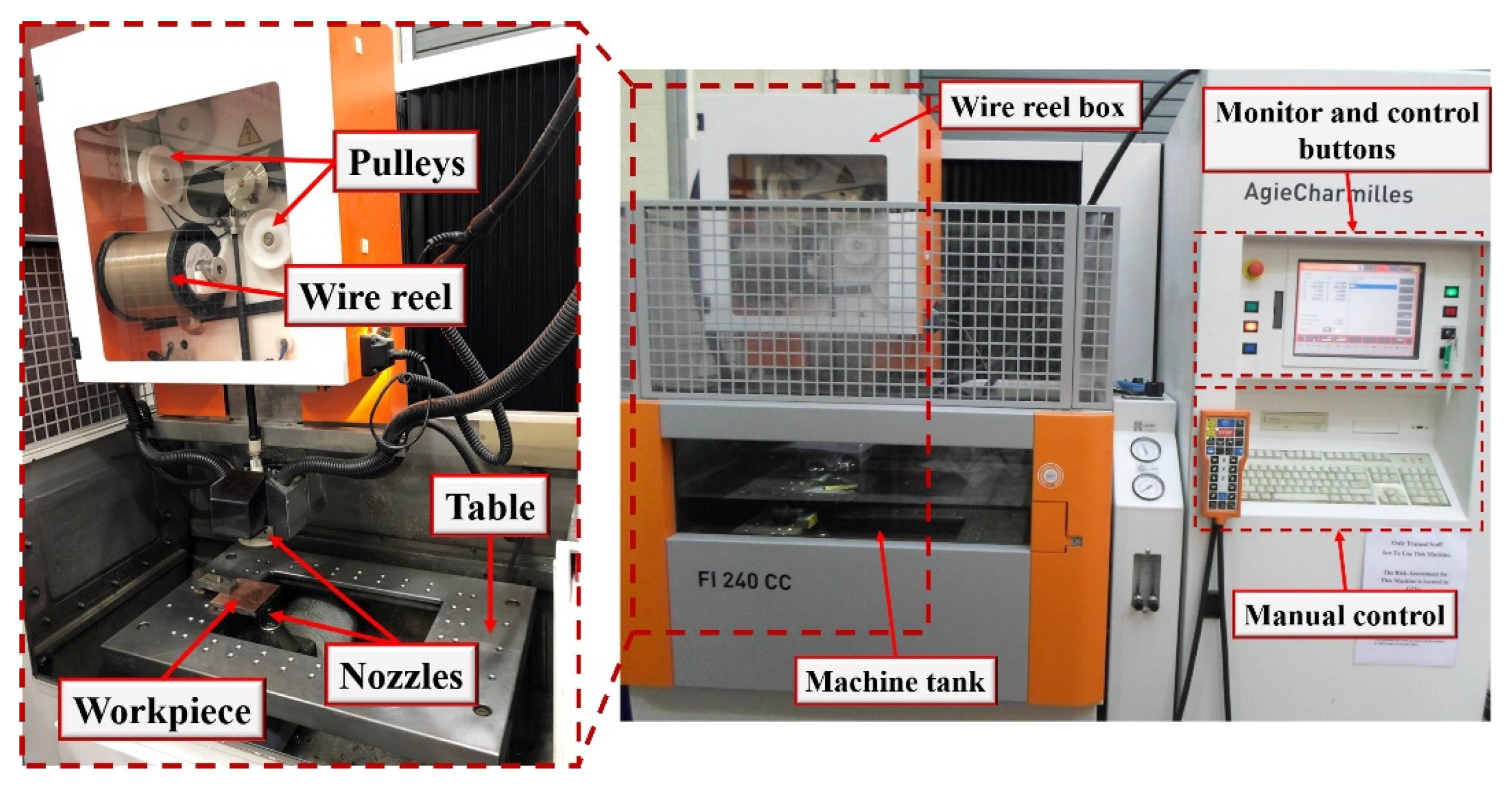
Figure 4.
Material removal rate in each test for the Topas and Compeed wire electrodes.

Figure 5.
Main effects plot for MRR.

Figure 6.
Optical micrographs of the kerf machined using Topas wire in Test 2 at the (a) top and (b) bottom surface.
Figure 6.
Optical micrographs of the kerf machined using Topas wire in Test 2 at the (a) top and (b) bottom surface.
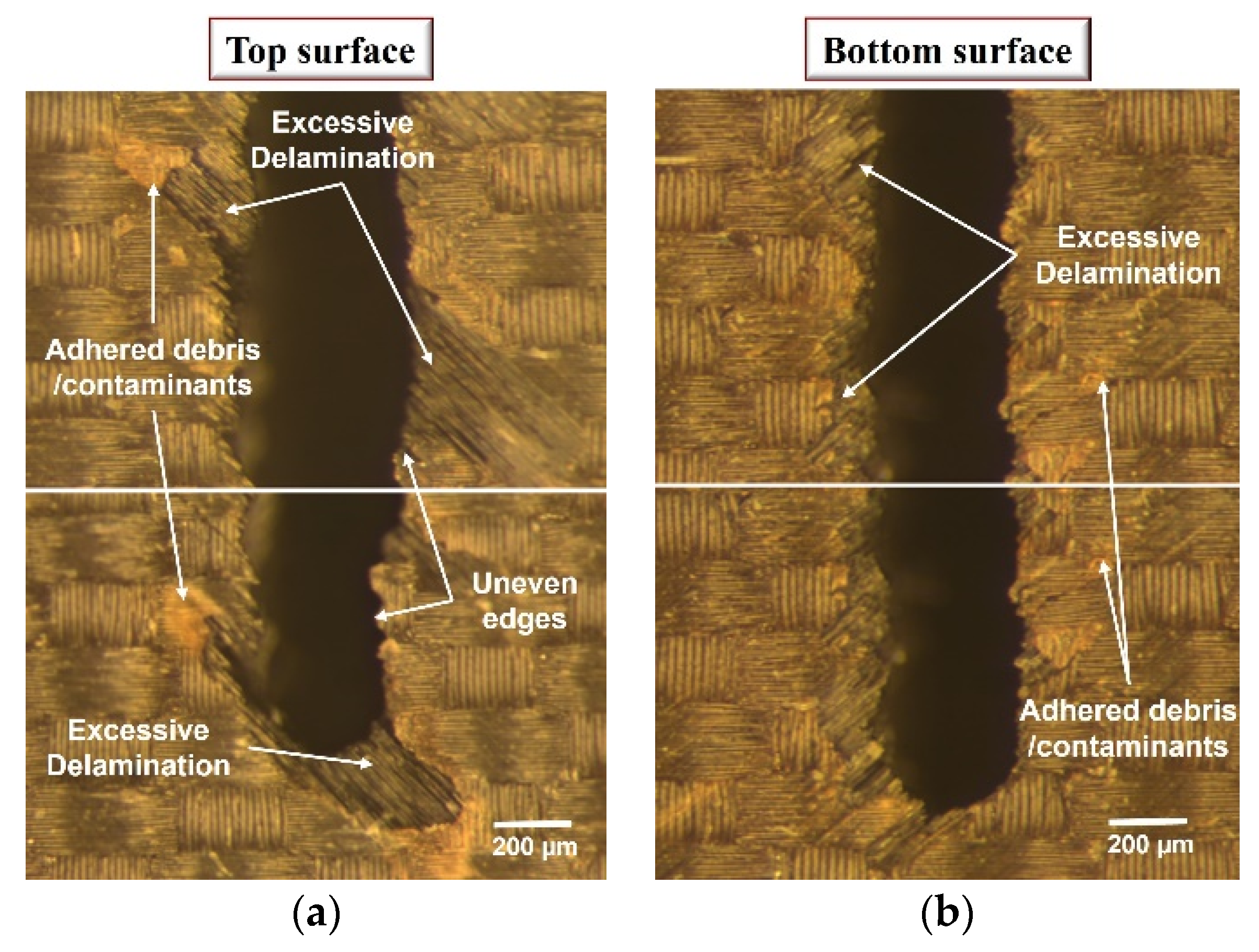
Figure 7.
Optical micrographs of the kerf machined using Compeed wire in Test 6 at the (a) top and (b) bottom surface.
Figure 7.
Optical micrographs of the kerf machined using Compeed wire in Test 6 at the (a) top and (b) bottom surface.
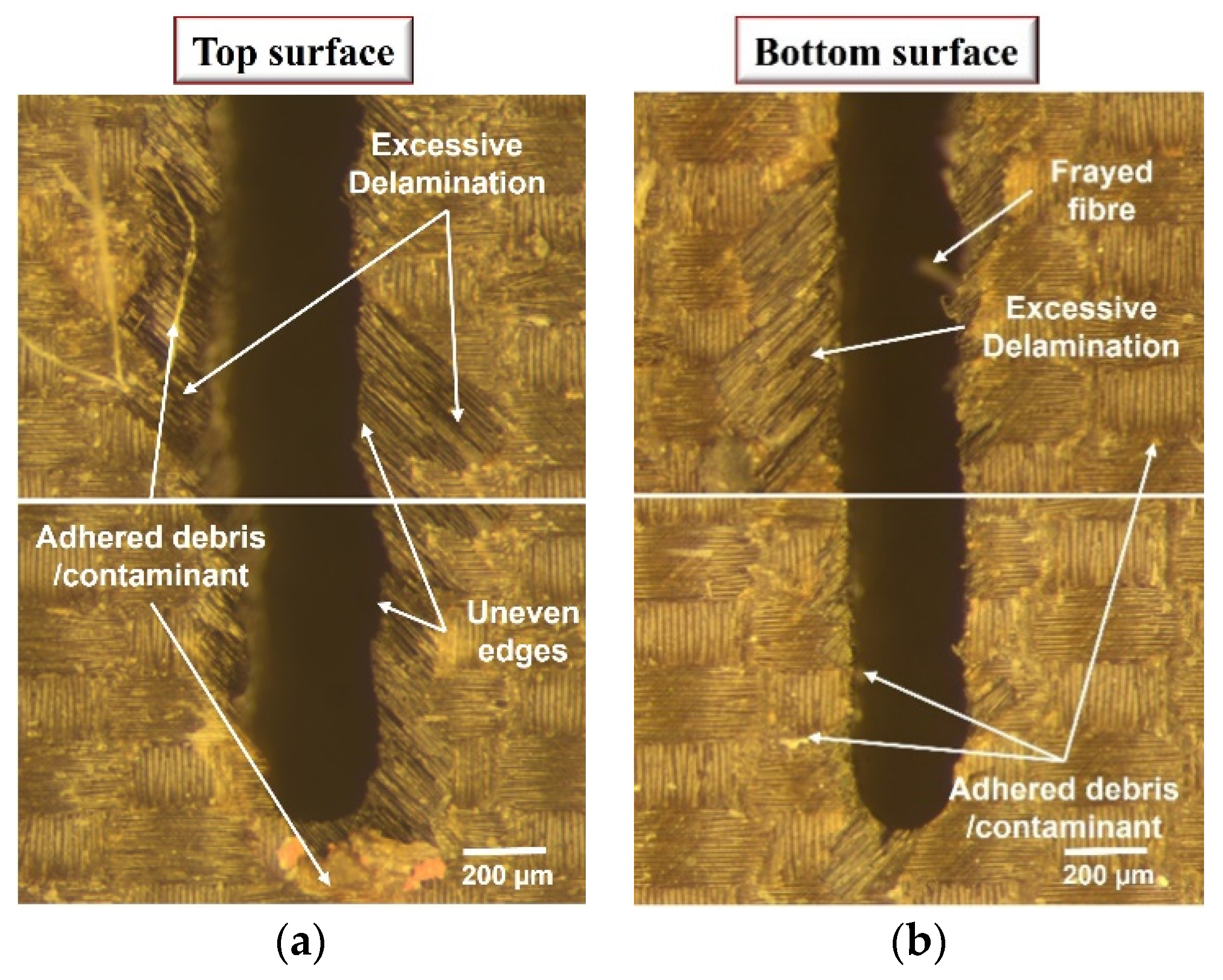
Figure 8.
Sample SEM micrographs of surfaces machined using the Topas wire in (a) Test 3 and (b) Test 2 and Compeed wire in (c) Test 7 and (d) Test 6.
Figure 8.
Sample SEM micrographs of surfaces machined using the Topas wire in (a) Test 3 and (b) Test 2 and Compeed wire in (c) Test 7 and (d) Test 6.

Figure 9.
Average kerf width in each test for the Topas and Compeed wire electrodes.
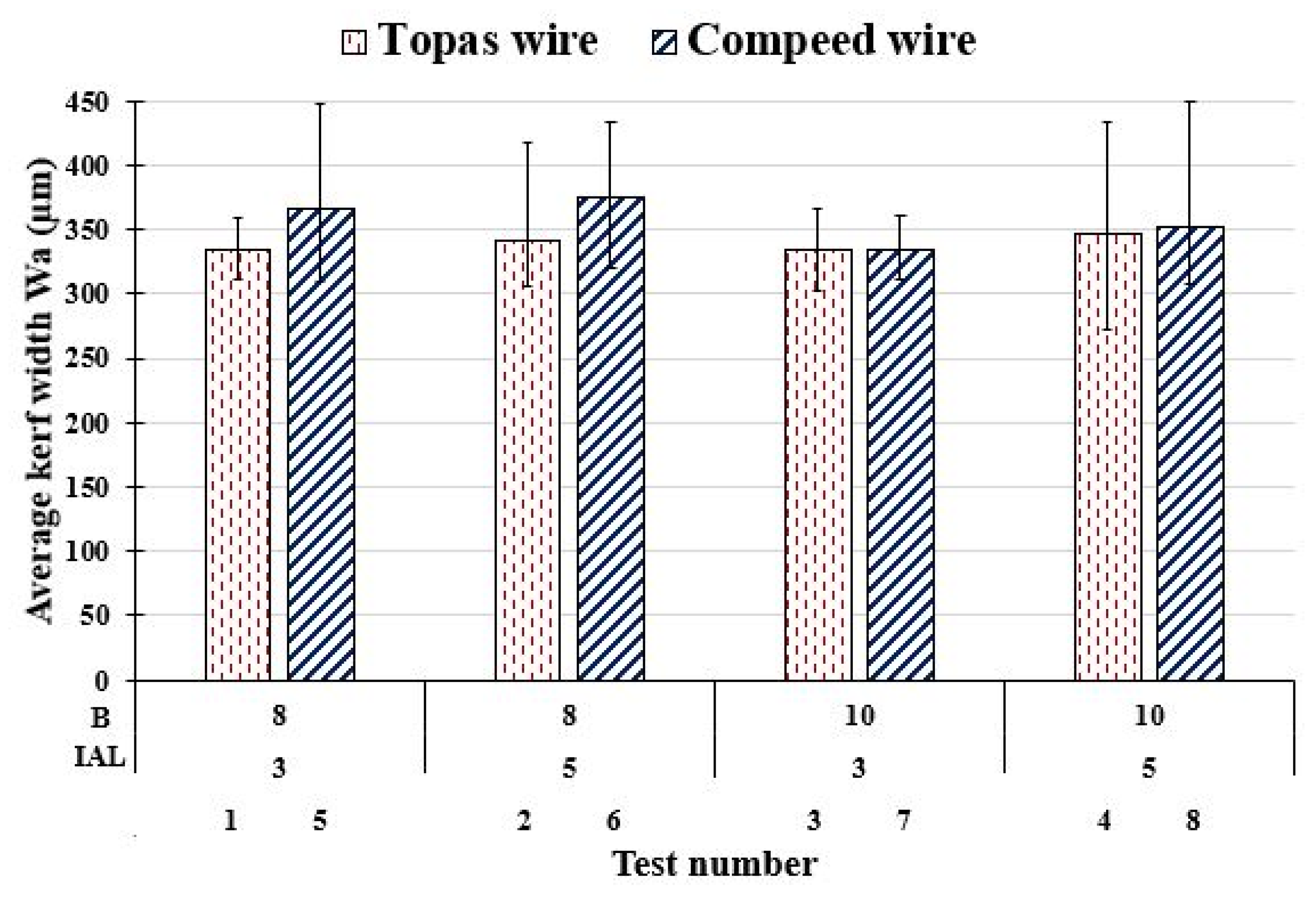
Figure 10.
Main effects plot for average kerf width.

Figure 11.
Average areal surface roughness in each test for the Topas and Compeed wire electrodes.

Figure 12.
Surface topographical map of workpiece machined with (a) Topas (Test 2) and (b) Compeed (Test 6) wires.
Figure 12.
Surface topographical map of workpiece machined with (a) Topas (Test 2) and (b) Compeed (Test 6) wires.
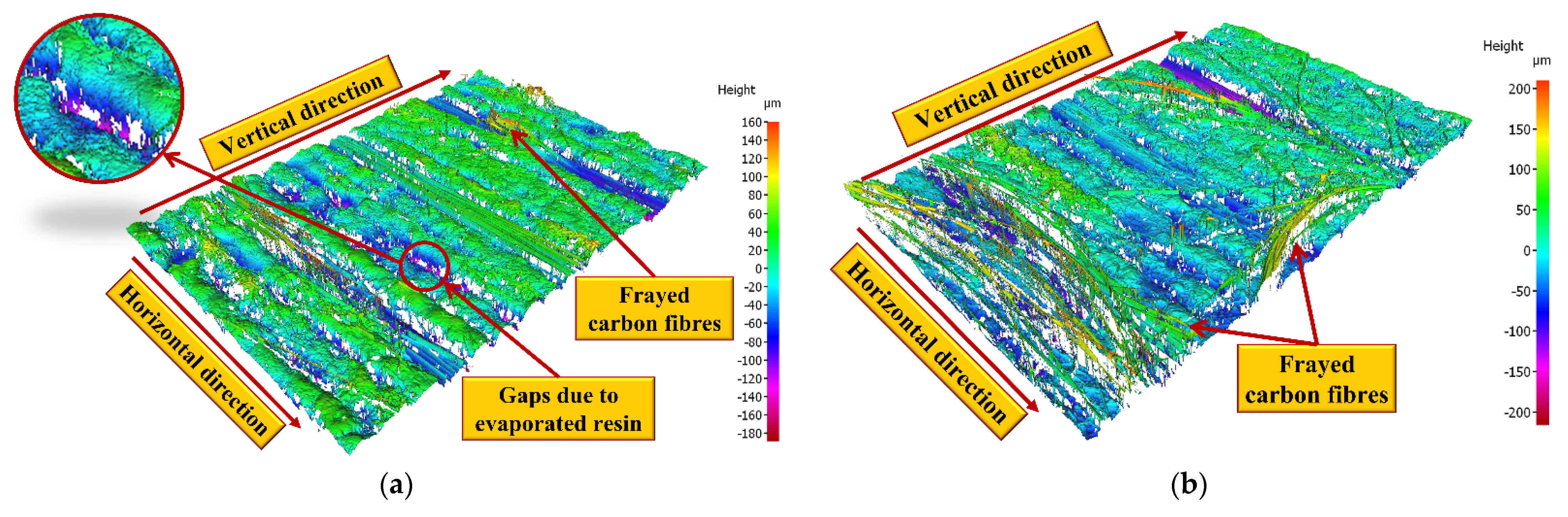
Figure 13.
Main effects plot for average surface roughness.


| Property | Details |
|---|---|
| Density | 1.6 g/cm3 |
| Hardness | 60–65 Barcol |
| Ultimate tensile strength | 2000 MPa |
| Interlaminate shear strength | 14 MPa |
| Modulus of elasticity | 150 GPa |
| Thermal conductivity | 1 W/mK ⊥ and 70 W/mK//to fibre |
| Workpiece electrical resistivity (X, Y, Z) | 0.0833 Ω·cm, 0.092 Ω·cm, 1980.1 Ω·cm |
| Coefficient of thermal expansion (CTE) | Up to 10 μm/mK |
Table 2.
Variable and constant parameters.
| Parameters | Symbol (Unit) | Level 1 | Level 2 | |
|---|---|---|---|---|
| Variable factors | Ignition current | IAL (A) | 3 | 5 |
| Pulse-off time | B (µs) | 8 | 10 | |
| Wire type | W | Topas Plus D (T) | Compeed (C) | |
| Constant factors | Open gap voltage | Vo (V) | 100 | - |
| Pulse-on time | A (µs) | 0.6 | - | |
| Servo voltage | Aj (V) | 15 | - | |
| Wire tension | WB (N) | 13 | - | |
| Wire speed | WS (m/min) | 10 | - | |
| Flushing pressure | INJ (bar) | 16 | - | |
| Frequency | FF (%) | 10 | - | |
Table 3.
Full factorial experimental array.
| Test No. | Ignition Current, IAL (A) | Pulse-off Time, B (µs) | Wire Type, W |
|---|---|---|---|
| 1 | 3 | 8 | T |
| 2 | 5 | 8 | T |
| 3 | 3 | 10 | T |
| 4 | 5 | 10 | T |
| 5 | 3 | 8 | C |
| 6 | 5 | 8 | C |
| 7 | 3 | 10 | C |
| 8 | 5 | 10 | C |
Table 4.
ANOVA for material removal rate including interactions.
| Source | DF | Seq SS | Adj SS | Adj MS | F-Value | p-Value | PCR |
|---|---|---|---|---|---|---|---|
| Model | 6 | 74.0556 | 74.0556 | 12.3426 | 80.07 | 0.085 | 99.79% |
| Linear | 3 | 73.597 | 73.597 | 24.5323 | 159.15 | 0.058 | 99.17% |
| IAL | 1 | 14.5094 | 14.5094 | 14.5094 | 94.13 | 0.065 | 19.55% |
| B | 1 | 50.281 | 50.281 | 50.281 | 326.19 | 0.035 * | 67.76% |
| W | 1 | 8.8065 | 8.8065 | 8.8065 | 57.13 | 0.084 | 11.87% |
| 2-Way Interactions | 3 | 0.4587 | 0.4587 | 0.1529 | 0.99 | 0.611 | 0.62% |
| IAL*B | 1 | 0.2877 | 0.2877 | 0.2877 | 1.87 | 0.402 | 0.39% |
| IAL*W | 1 | 0.001 | 0.001 | 0.001 | 0.01 | 0.949 | 0.00% |
| B*W | 1 | 0.17 | 0.17 | 0.17 | 1.1 | 0.484 | 0.23% |
| Error | 1 | 0.1541 | 0.1541 | 0.1541 | 0.21% | ||
| Total | 7 | 74.2098 | 100.00% | ||||
| Model equation | MRR = 34.40 − 0.36 IAL − 3.266 B + 0.22 W + 0.190 IAL*B + 0.011 IAL*W − 0.146 B*W | ||||||
| Model summary | |||||||
| S | R2 | Adj R2 | PRESS | Pred R2 | |||
| 0.392615 | 99.79% | 98.55% | 9.86536 | 86.71% | |||
* Significant at the 5% level.
Table 5.
ANOVA for average kerf width including interactions.
| Source | DF | Seq SS | Adj SS | Adj MS | F-Value | p-Value | PCR |
|---|---|---|---|---|---|---|---|
| Model | 6 | 1701.86 | 1701.86 | 283.643 | 135.34 | 0.066 | 99.88% |
| Linear | 3 | 1195.78 | 1195.78 | 398.592 | 190.19 | 0.053 | 70.18% |
| IAL | 1 | 272.42 | 272.42 | 272.422 | 129.99 | 0.056 | 15.99% |
| B | 1 | 281.11 | 281.11 | 281.111 | 134.13 | 0.055 | 16.50% |
| W | 1 | 642.24 | 642.24 | 642.244 | 306.45 | 0.036 * | 37.69% |
| 2-Way Interactions | 3 | 506.08 | 506.08 | 168.693 | 80.49 | 0.082 | 29.70% |
| IAL*B | 1 | 34.33 | 34.33 | 34.332 | 16.38 | 0.154 | 2.01% |
| IAL*W | 1 | 5.08 | 5.08 | 5.084 | 2.43 | 0.363 | 0.30% |
| B*W | 1 | 466.66 | 466.66 | 466.664 | 222.67 | 0.043 * | 27.39% |
| Error | 1 | 2.1 | 2.1 | 2.096 | 0.12% | ||
| Total | 7 | 1703.95 | 100.00% | ||||
| Model equation | Wa = 452.4 − 12.81 IAL − 14.21 B + 74.51 W + 2.072 IAL*B + 0.797 IAL*W − 7.638 B*W | ||||||
| Model summary | |||||||
| S | R2 | Adj R2 | PRESS | Pred R2 | |||
| 1.44767 | 99.88% | 99.14% | 134.129 | 92.13% | |||
* Significant at the 5% level.
Table 6.
ANOVA for average surface roughness.
| Source | DF | Seq SS | Adj SS | Adj MS | F-Value | p-Value | PCR |
|---|---|---|---|---|---|---|---|
| Model | 6 | 19.9873 | 19.9873 | 3.33121 | 4.27 | 0.355 | 96.24% |
| Linear | 3 | 12.4798 | 12.4798 | 4.15992 | 5.33 | 0.306 | 60.09% |
| IAL | 1 | 8.6433 | 8.6433 | 8.6433 | 11.07 | 0.186 | 41.62% |
| B | 1 | 3.2123 | 3.2123 | 3.21231 | 4.12 | 0.292 | 15.47% |
| W | 1 | 0.6242 | 0.6242 | 0.62416 | 0.8 | 0.536 | 3.01% |
| 2-Way Interactions | 3 | 7.5075 | 7.5075 | 2.5025 | 3.21 | 0.385 | 36.15% |
| IAL*B | 1 | 0.0039 | 0.0039 | 0.00389 | 0 | 0.955 | 0.02% |
| IAL*W | 1 | 4.0162 | 4.0162 | 4.0162 | 5.14 | 0.264 | 19.34% |
| B*W | 1 | 3.4874 | 3.4874 | 3.4874 | 4.47 | 0.281 | 16.79% |
| Error | 1 | 0.7806 | 0.7806 | 0.7806 | 3.76% | ||
| Total | 7 | 20.7679 | 100.00% | ||||
| Model equation | Sa = 26.9 + 0.84 IAL − 0.72 B + 3.39 W + 0.022 IAL*B + 0.709 IAL*W − 0.660 B*W | ||||||
| Model summary | |||||||
| S | R2 | Adj R2 | PRESS | Pred R2 | |||
| 0.883518 | 96.24% | 73.69% | 49.9587 | 0.00% | |||
Publisher’s Note: MDPI stays neutral with regard to jurisdictional claims in published maps and institutional affiliations. |
© 2022 by the authors. Licensee MDPI, Basel, Switzerland. This article is an open access article distributed under the terms and conditions of the Creative Commons Attribution (CC BY) license (https://creativecommons.org/licenses/by/4.0/).
Share and Cite
MDPI and ACS Style
Abdallah, R.; Hood, R.; Soo, S.L. The Machinability Characteristics of Multidirectional CFRP Composites Using High-Performance Wire EDM Electrodes. J. Compos. Sci. 2022, 6, 159. https://doi.org/10.3390/jcs6060159
AMA Style
Abdallah R, Hood R, Soo SL. The Machinability Characteristics of Multidirectional CFRP Composites Using High-Performance Wire EDM Electrodes. Journal of Composites Science. 2022; 6(6):159. https://doi.org/10.3390/jcs6060159
Chicago/Turabian StyleAbdallah, Ramy, Richard Hood, and Sein Leung Soo. 2022. "The Machinability Characteristics of Multidirectional CFRP Composites Using High-Performance Wire EDM Electrodes" Journal of Composites Science 6, no. 6: 159. https://doi.org/10.3390/jcs6060159