Article

Mechanical Properties and Fatigue Performance of 17-4 PH Stainless Steel Manufactured by Atomic Diffusion Additive Manufacturing Technology

1
Manufacturing Department, Faculty of Engineering, Mondragon Unibertsitatea, 20500 Mondragon, Spain
2
Engineering Department, Campus Goierri, Mondragon Unibertsitatea, 20240 Ordizia, Spain
3
Materials Department, Faculty of Science and Engineering, The University of Manchester, Manchester M13 9PL, UK
*
Author to whom correspondence should be addressed.
J. Manuf. Mater. Process. 2023, 7(5), 172; https://doi.org/10.3390/jmmp7050172
Submission received: 16 August 2023 / Revised: 13 September 2023 / Accepted: 22 September 2023 / Published: 26 September 2023
(This article belongs to the Special Issue Advanced Manufacturing Technologies for High-Strength Steels)

Abstract

:
Additive Manufacturing (AM) is gaining importance as an alternative and complementary technology to conventional manufacturing processes. Among AM technologies, the Atomic Diffusion Additive Manufacturing (ADAM) technology is a novel extrusion-based process involving metallic filaments. In this work, the widely used 17-4 PH stainless steel filament was selected to study the effect of different deposition strategies of ADAM technology on mechanical properties. The printed parts had mechanical properties comparable to those obtained by other more developed AM technologies. In the case of tensile and fatigue tests, obtained values were in general greatly affected by deposition strategy, achieving better results in horizontal built orientation specimens. Interestingly, the effect was also considered of machining post-process (turning), which in the case of the tensile test had no remarkable effect, while in fatigue tests it led to an improvement in fatigue life of two to four times in the tested range of stresses.

1. Introduction

This study is focused on investigating the mechanical properties of 17-4 precipitation hardening (PH) stainless steel (SS) parts, referred to commonly as 17-4 PH SS, produced by the novel Atomic Diffusion Additive Manufacturing (ADAM) technology. PH SSs are widely used in metal Additive Manufacturing (AM) due to their excellent weldability and high strength and corrosion resistance compared to austenitic steels [1,2], making them suitable for Powder Based Fusion (PBF) and Direct Energy Deposition (DED) technologies. Precisely, 17-4 PH SS is the most widely used type of PH SS because of its high tensile strength, high toughness and high corrosion resistance at temperatures below 315 °C [2]. Interestingly, the novel Atomic Diffusion Additive Manufacturing (ADAM) technology, commercialized by Markforged®, which was officially launched into the market in 2017, can be a great alternative to manufacture 17-4 PH SS parts efficiently.
ADAM technology, which is a printing technique that resembles the well-known and developed Fused Deposition Modelling (FDM) technology [3], is based on three independent stages: printing, washing and sintering. In the printing stage, the geometrical shape of the part is achieved, called the green part. A filament composed of metal powder enclosed in a mix of wax and thermoplastic polymer matrix which works as a binder for the metallic particles is used as raw material [4]. The filament goes through a heated unit which softens the polymer matrix, and at the end of the unit a nozzle is used to deposit the material in the built plate. Repeating the same process layer by layer, the desired part is obtained [3].
Two deposition strategies are combined in each layer when using ADAM technology. Firstly, the material is extruded following the shape of the part, using a contour strategy, and secondly the infill of the part is performed to finish the layer. The infill can be done by creating a triangular lattice, which reduces part weight, or by a zig zag solid infill strategy depending on part requirements. Each infill zig zag layer is deposited perpendicularly with respect to the orientation of the zig zag of the preceding layer. Figure 1a shows the theoretical path of the infill and contour deposition strategies in a circular layer, and Figure 1b a macroscopic image of a section/layer of an actual part where a region of the succeeding infill layer can be seen deposited perpendicularly.
As in other AM technologies, support structures are generated with the ADAM process if the part presents an overhang feature with ≤45°. The supports and the part are manufactured with the same material but supports are always printed using the triangular lattice infill deposition strategy as they have no functional requirements. Importantly, in contrast to other methods of metallic additive manufacturing, a ceramic layer of identical dimensions to the metallic component is incorporated between the part and the support structure. This step aids in the easier removal of the support structure during the final phase. In Figure 2a, an example of a designed part is shown with a 45° overhang feature, and Figure 2b shows the support structure of the printed part.
In the second phase, known as debinding or washing, green parts undergo immersion in a liquid solvent at a specific temperature and duration to effectively eliminate the majority of the wax binding material. Larger parts necessitate extended soaking periods due to the solvent’s difficulty in penetrating the core of the component. The resulting washed parts, which are quite brittle and require delicate handling, are referred to as brown parts. To assess the progress, the part’s weight is measured both before and after immersion in the solvent. As per recommendations from material suppliers, for the material 17-4 PH SS, brown parts should exhibit a weight reduction of 4.1% or less than their green counterparts to be deemed ready for the final sintering stage.
Finally, the sintering stage is divided in two main phases, as shown in Figure 3a. Sintering takes place in a controlled atmosphere furnace, where a fixed flow of inert gas mix of argon and hydrogen fills the furnace chamber to protect the parts from oxidation. First, the furnace is heated up to melt and remove the remaining wax and thermoplastic polymer binder. Then, the temperature is risen near to the material’s melting point, but always below it. At such a temperature, diffusion bonding takes place, and all metal powder particles are joined, obtaining almost fully dense final parts. Measuring the difference between the brown and sintered part dimensions, shrinkage of around 18% in size was observed in this sintering phase [5]. An example of the shrinkage is shown in Figure 3b,c.
This novel way of manufacturing metallic parts offers some advantages with respect to other AM technologies [5]: (i) the residual stresses are lower due to the small temperature gradients of the sintering stage; (ii) toxicity and flammability risks of working with loose metallic powder are removed; (iii) there is a possibility of creating cavities that other powder-based AM technologies are not able to achieve and (iv) facility in removing support structures.
Since ADAM is an emerging technique, only a few studies have been published in the scientific community reporting the advances in this manufacturing technology. Galati and Minetola [3] were the first to study 17-4 PH SS parts manufactured by ADAM technology. They measured the density, surface roughness and part dimensional accuracy of printed parts. Although poor relative density and surface roughness values were achieved, similar dimensional accuracy to casting or forming was measured. Gonzalez et al. [6] measured the tensile proprieties of this material, and reported tensile data with a maximum standard deviation of 38%, which was attributed to defects induced during the printing. Bouaziz et al. [7] analyzed the effect of heat treatment on this material, showing a significant effect on tensile properties but no remarkable effect on surface roughness. Most recently, Pellegrini et al. [8], showed an important influence of the aging treatments on hardness and porosity. On the other hand, Henry et al. [9] focused on determining the influence of printing orientations on the tension, shear, and bending response. They found that the strength is best along the extrusion direction and worst in the extrusion direction. Similar behavior was reported by Alkindi et al. [10].
The results reported in these papers demonstrate that ADAM can obtain mechanical properties comparable to those of conventional and other AM processes. However, Abe et al. [11] attribute the poor tensile behavior of the printed samples in certain directions to a general problem of metal fused deposition techniques that might be avoided by improving the raw material, in particular changing the binder presence in the filament by optimizing the polymer composition. Ensuring good static mechanical properties could be enough for a wide range of applications, but many structural components must withstand cyclic loads. Therefore, we need to characterize the fatigue behavior of parts produced by ADAM technology for correct design. It is well known that surface roughness and sub-surface defects, such as pores, cavities or inclusions, generate stress concentrations which favors crack initiation and its propagation [12]. Therefore, it is mandatory to study the fatigue performance of AM parts. Within this context, many previous works can be found in the literature analyzing the fatigue performance of AM parts. However, these are mainly focused on the most developed PBF and DED technologies [13,14]. To the best of the authors’ knowledge, no previous research on fatigue performance for parts manufactured by ADAM has been reported in the literature.
The main objective of this work is to mechanically characterize 17-4 PH SS parts printed by ADAM technology, focusing on the relative density, elastic modulus and mechanical properties (such as yield and tensile strength and maximum elongation), hardness, surface roughness and, particularly, fatigue behavior. Moreover, the built orientation also plays a key factor in fatigue performance [15]. Thus, this work also studies the effect of deposition strategy as well as machining post-processing on strength, ductility and fatigue behavior. Additionally, a first insight into the composition and properties of the commercial filaments was carried out.
Firstly, details of the material and manufacturing system are described. Then, the methodology followed to characterize the density, surface roughness, hardness, tensile tests and fatigue tests is explained. Subsequently, results are presented and discussed. Finally, conclusions are drawn and suggestions for further research are made.

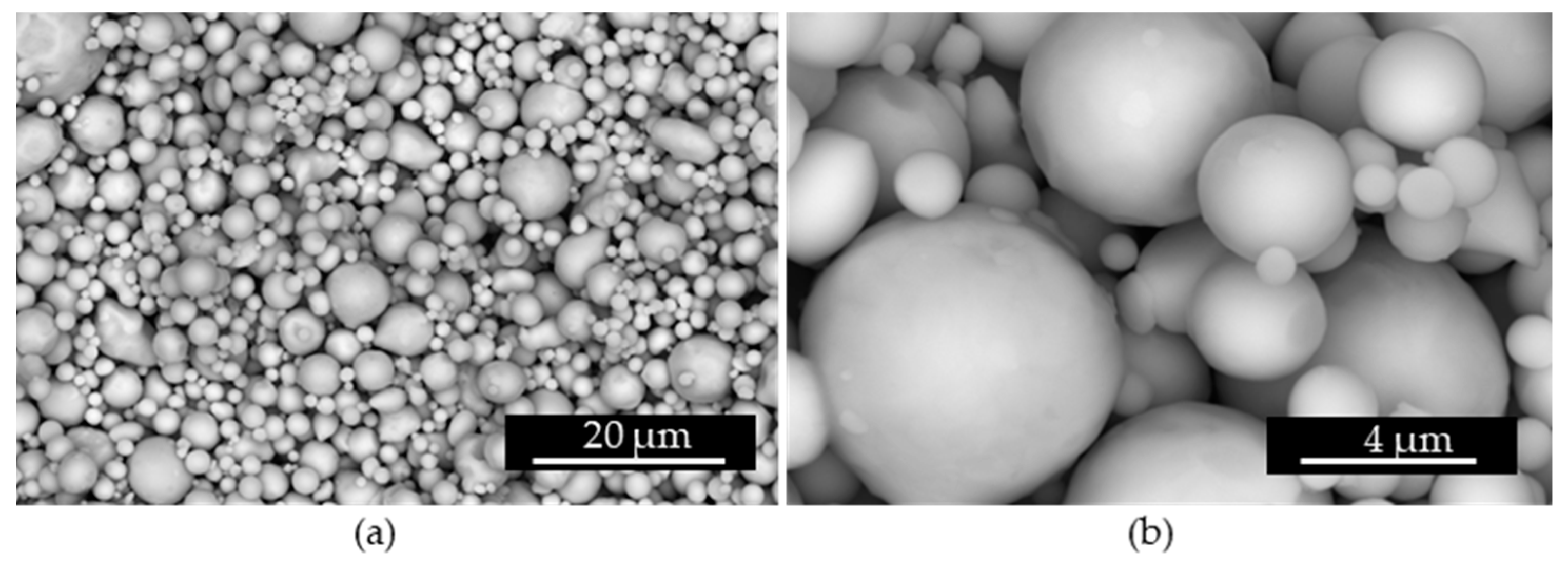
2. Material and Manufacturing System

In this work, the Metal X system developed by Markforged, was used to manufacture the standardized specimens using ADAM technology. The Metal X system has a dedicated unit for each step of the manufacturing process: Metal X for the first extrusion step, Wash-1 for the second debinding step and Sinter-1 for the last sintering step. The high level of automatization of the Metal X system facilitates the manufacturing of parts. However, this limits the researchers in optimizing any of the stages of the manufacturing route.
The material employed was 17-4 PH SS filament commercialized by Markforged [16]. This filament is based on a polymeric matrix filled with 17-4 PH SS powder. Table 1 shows the chemical composition of the metal powder supplied by the manufacturer.
In order to have a better understanding of the polymer elimination process that takes place during sintering, Thermogravimetric Analysis (TGA) of the commercial filament was carried out from ambient temperature to 550 °C with a heating rate of 5 °C/min employing a thermogravimetric analyser STA 449 F3 Jupiter (NETZSCH).
Figure 4 shows the thermograms of two samples of the commercial filament. It can be observed that roughly 7 wt% of the original mass of the filament is eliminated during the thermal treatment. Two different steps can be clearly identified in both samples, which reveals the presence of two different polymers in the filament. Approximately, 3–4 wt% is eliminated in the range between 200 and 300 °C, while the rest is eliminated between 400 and 450 °C, as is usual for FDM polymers, like ABS and PC [17].
This is related to the composition of the polymer matrix present in the filament, which is a mixture of a wax and a polymer. The organic element that is eliminated at lower temperatures is the wax (mainly eliminated during washing). The wax has a specific function during sintering, allowing the formation of holes that will facilitate the elimination of the polymer at the sintering step, avoiding the formation of cracks during polymer elimination. Consequently, an accurate control of the elimination of the wax and the following thermal elimination of the polymer are critical for the manufacturing of dense parts and the desired microstructure.
In addition, the powder remaining after TGA was observed in a FEI Nova NanoSEM 450, a Scanning Electron microscope (SEM) working with a 30 kV of HV, a spot size of 6.0 and a working distance of 9.8 mm. As can be seen in Figure 5, the particle size is up to 10 μm, the presence of particles smaller than 2 μm being significant, which is appropriate for the employed printer nozzle.

3. Methods

Four types of specimens were manufactured: (i) cubic samples for density measurements, (ii) tensile test specimens, (iii) samples for surface roughness and hardness measurements and (iv) fatigue test specimens. The geometry of these specimens is described in the following subsection. All specimens were manufactured with a solid infill pattern and a layer height of 125 µm in the extrusion stage. Most of the samples were manufactured with a contour layer thickness of 1 mm, but 0.5 mm in some tensile test specimens and 2 mm in some fatigue test specimens were also used. For washing, the solvent Opteon SF-79 was used. The final sintering cycle was applied in the Sinter-1 furnace [18], whose properties are not detailed by the supplier.

3.1. Density Measurements

The Standard ASTM B962 [19] was followed for density measurements. Part density (ρp) and relative density (RD) values were calculated by Equations (1) and (2), respectively, where ρw is the density of the distilled water, ma is the mass of the dry part, mfl is the mass of the part while being immersed in water and ρc is the theoretical real density of the raw material (7.75 g/cc).
ρ p = ρ w · m a m a m f l  
R D   ( % ) = ρ p   ρ c · 100
Three samples of cube shape with a side of 2 cm, an approximate volume of 8 cm3 were used for this study. Each mass measurement was performed three times to obtain reliable results.

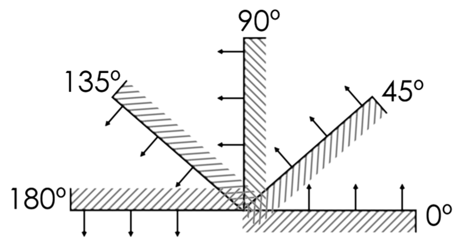
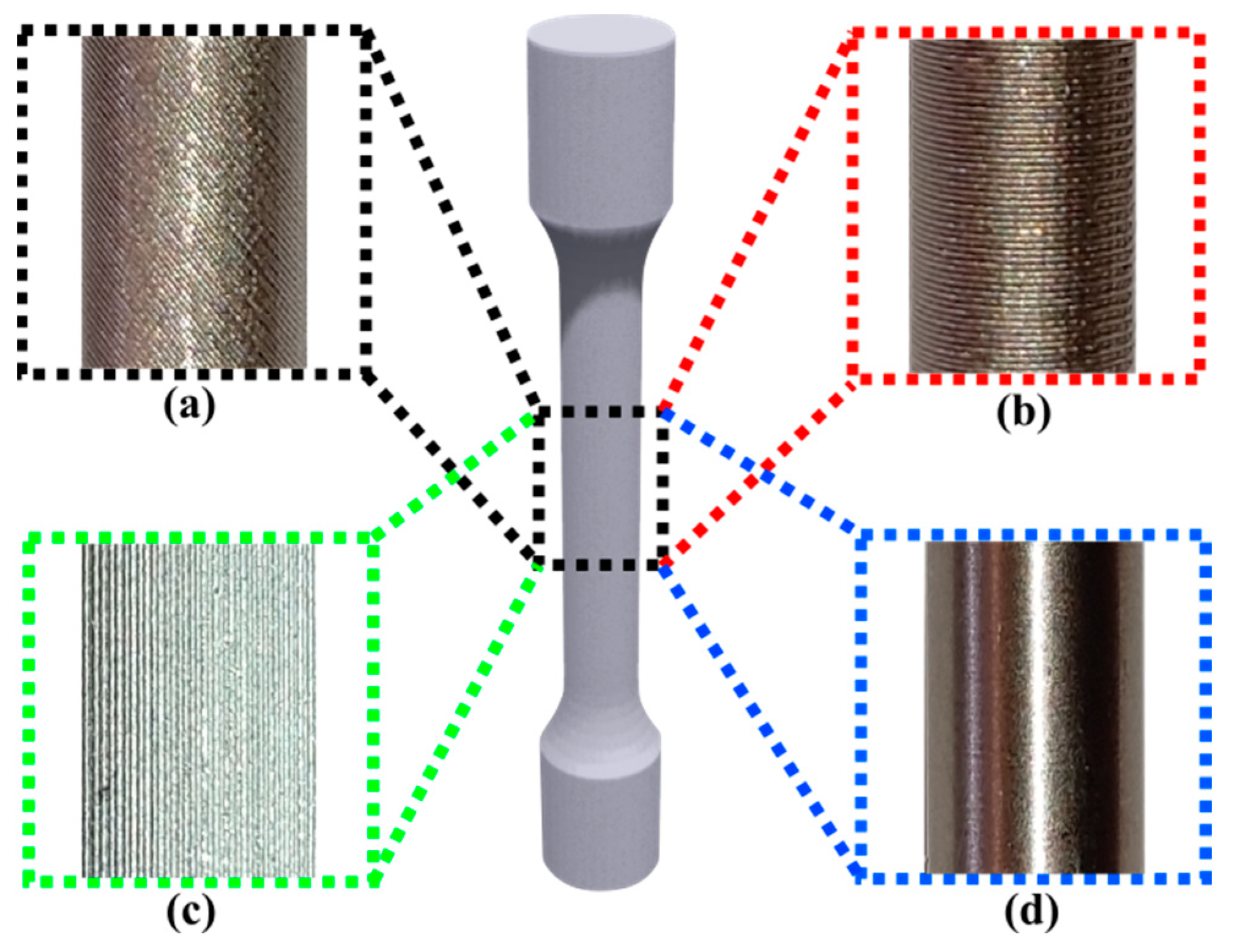
3.2. Surface Roughness Measurements

In order to analyse the surface roughness in different plane angles, four different wedges were manufactured. With them, surface roughness was measured in the following planes: 0°, 30°, 45°, 60°, 90°, 135° and 180°, as shown in Figure 6. Figure 2a shows one of these wedges, where 0, 90 and 135° plane angles are available. The surfaces with an angle of over 135° require a support structure, which must be removed after sintering. Three linear measurements were made in each plane angle. The arithmetical mean deviation of the assessed profile (Ra), the average of the maximum peak to valley height of the profile over assessed length (Rz) and the largest single roughness depth within the evaluation length (Rmax) were measured using a portable roughness Hommel Tester T500. The assessment length was 4.8 mm.

3.3. Hardness Measurements
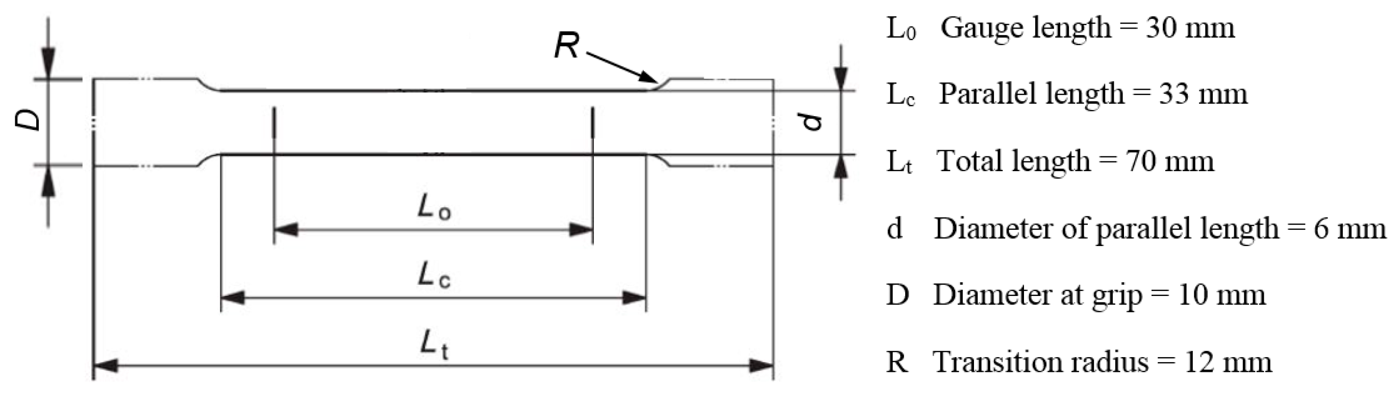
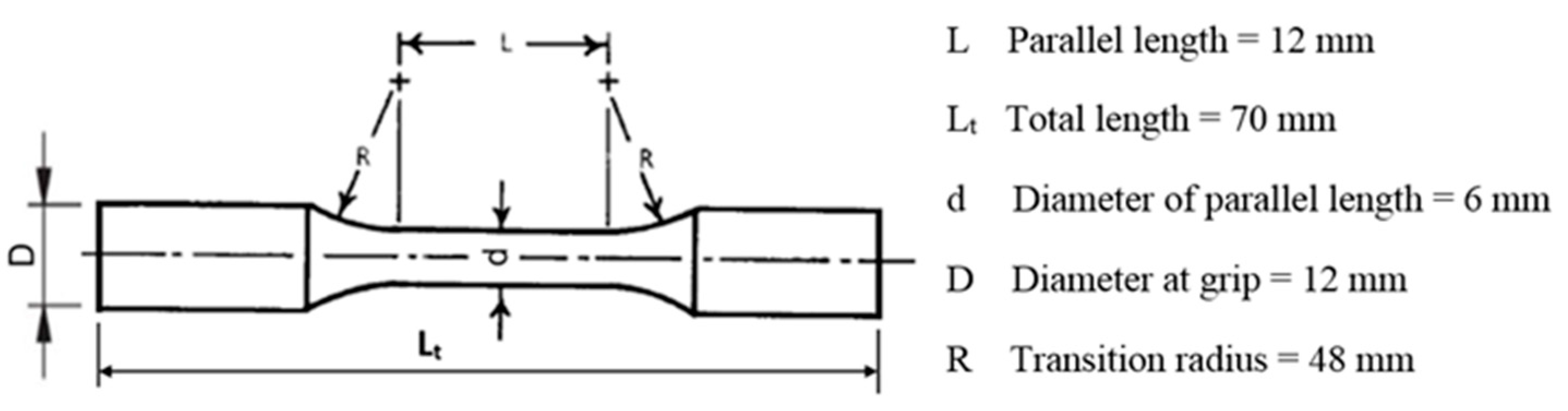
Characterization of hardness was done in the specimens used in roughness measurements. Prior to hardness tests, the surfaces were polished, using first 240 µm, then 600 µm, afterwards 800 µm and finally 1200 µm sandpaper. A Zwick Vickers hardness tester was used applying 10 kg for 10 s. Five measurements were made in all plane angles.

3.4. Tensile Tests

To determine the strength and ductility of the material, tensile tests were done at room temperature. The specimens were designed following the European Standard ISO 6892-1 [20]. The geometry of the specimen is shown in Figure 7.
To study the effect of deposition strategy and post-process operation (machining) on mechanical properties (strength and ductility), 12 tensile (4 sets) specimens were manufactured and tested: three as built specimens with a 45° inclination (Figure 8a), three as built oriented in the vertical direction (Figure 8b), three as built oriented in the horizontal direction (Figure 8c) and three specimens printed in the horizontal direction for machining postprocessing (Figure 8d).
Figure 9 shows cross-section images of tensile specimens taken by optical microscope Leica DMi8C. Figure 9a shows the cross-section of an as built vertical specimen and Figure 9b the cross-section of an as built horizontal, both images taken with 5× magnification. The core of both cross-sections was also analysed with 50× magnification images (Figure 9c for vertical and Figure 9d for horizontal) to discover that the micropores found in both cases where identical in shape, size and quantity. Using the image-analysis software LAS V 4.12, the density of three vertical cores and three horizontal cores were measured, obtaining values of 99.02 ± 0.09 in the vertical and 98.93 ± 0.03 in the horizontal. Note that these values are not meant to show part density values, rather to demonstrate that the microporosity of the core material is the same regardless of the orientation. The same behaviour was reported by Cho et al. [21].
However, lack of adhesion between extruded filaments can be observed in the contour. The cavities shown in the blue dotted-lines show exactly the same problematic in both Figure 9a,b; the different orientation of the specimens is what makes them look different. The cross-section of the vertical specimen shows the lack of adhesion between the extruded filament in the same layer, while the cross-section of the horizontal shows the lack of adhesion between different layers.
In the author’s opinion, this lack of adhesion could be prevented by changing some printer parameters, like the nozzle temperature or the extrusion overlap. However, these parameters cannot be modified in this particular printer.
Due to the defects found in the contour, the three specimens to be postprocessed by machining were manufactured with radial oversize of 0.8 mm, including a 0.5 mm thick contour layer. These specimens were then turned using a lathe, removing radially 0.8 mm from the surface and obtaining the geometry of standardized specimens (Figure 7). This procedure removes the porous 0.5 mm thick contour layer and consequently will lead to improved strength and ductility properties. Specimens were turned using a SANDVIK VBMT 11 03 04 PF—4225 insert, cutting speed of 50 m/min, depth of cut of 0.25 mm and feed rate of 0.1 mm/rev.
Tested deposition strategies produced different surface texture in the axial direction of tensile specimens, as shown in Figure 10a–c. In Figure 10d, it can be seen that no trace of deposition strategy is left after the specimen is machined.
Tensile tests were carried out using the universal machine INSTRON 3369 and a self-supporting macro extensometer was used to measure the strain. All tensile tests were carried out with a strain rate of 3 mm/min in the elastic zone and 10 mm/min in the plastic zone.

3.5. Fatigue Tests

Three sets of specimens were manufactured to study the effect of deposition strategy and post-processing on fatigue behavior of 17-4 PH SS specimens printed by ADAM technology. Figure 11 shows the geometry of the fatigue specimens’ designed according to the Standard ASTM E466 (2002) [22]. A total of 21 fatigue specimens were manufactured and tested: to obtain the first insight of the high cycle fatigue (HCF), a reference SN fatigue curve was made with 15 as built horizontal specimens. The influence of the deposition strategy on fatigue behavior was assessed using three as built vertical specimens, and finally three specimens printed in the horizontal direction and then machined were tested to analyze the effect post-processing on fatigue strength.
The machine tool manufacturer Markforged [22] recommends not to remove all the contour layer, because this compromises part strength. In this case, and in contrast to what was done with tensile specimens, the amount of material being removed was established to improve the surface roughness values, but without removing all the contour layer. The contour layer thickness of fatigue specimens was 2 mm, measured in a cross-section by optical microscopy, and printed with radial oversize of 0.5 mm. These specimens were turned in a lathe, removing radially a 0.5 mm thick layer to obtain the standardized specimens shown in Figure 11. The specimens were turned using a SANDVIK VBMT 11 03 04 PF—4225 insert, a cutting speed of 50 m/min, depth of cut of 0.25 mm and feed rate of 0.1 mm/rev.
Fatigue tests were carried out following the Standard ASTM E466 (2002). Tests were carried out in force-controlled mode at room temperature using the Material Testing System (MTS) 810. All tests were performed with a stress ratio of R = −1, with maximum stresses below the yield stress, and a frequency of 10 Hz. The run-out level was set at 2‧106 cycles. The tests were stopped when the run-out level was reached or when the specimen was broken. To determine the cause of the fatigue failure, a fractography analysis was performed on all fractured surfaces employing a Leica macroscope.

4. Results

4.1. Surface Roughness Values

Figure 12 shows the values of roughness Ra, Rz and Rmax with respect to the plane angle, as explained in Section 3.2. The best value for roughness parameters was found in the horizontal plane (0°): Ra of 10 ± 1.4 µm, Rz of 51.2 ± 4.1 µm and Rmax of 63.9 ± 4.1 µm, which was similar to those obtained at 60° and 90°. When comparing the horizontal plane with the 180° plane, the difference could be explained by the fact that at 180° the surfaces were in contact with a single thin layer of the ceramic release from the supporting structure.
On the other hand, surfaces at 45° and 60° angles showed a stepped effect due to small discontinuities between the layers; the higher the layer height, the rougher the inclined surface. Interestingly, when examining the 135° surfaces (fabricated with support), similar roughness values were achieved to those of 45°. This suggests that the presence of support structures does not contribute additionally to roughness when observing the stepped effect. This could be related to the fact that on the inclined surfaces the deposited ceramic is in contact with the metallic material of its own layer and the ceramic of the layer below, generating an smother support surface, which is not the case for the 180°. However, obtained roughness values can be improved by conventional post-processes such as machining or polishing, which can be used when necessary.

4.2. Density and Mechanical Properties

The samples produced by ADAM technology had a relative density of 96.1 ± 0.2%, which is the expected valued according to [16]. In contrast to surface roughness, no difference in surface hardness was measured in different plane angles, obtaining an average value of HV1 296 ± 29.
The elastic modulus, yield stress, tensile strength and the maximum elongation of the four types of specimens characterized in the tensile tests are summarized in Table 1, where refences values found in the literature are also collected for further comparison. All values are given as the arithmetical mean of the performed tests and the corresponding standard deviation.
Figure 13 compares the average values of the stress–strain curves of the four tested conditions. The specimens produced in the horizontal direction had a tensile stress of 1125 ± 10 MPa, which was almost two times higher than the samples printed in the vertical direction and at 45° orientation. The tensile strength of the specimen produced in the horizontal direction was barely affected by the subsequent machining process. The ductility of specimens printed in the horizontal direction was also significantly higher than the other as built specimens.

4.3. Fatigue Behavior

Figure 14 shows the results (stress amplitude vs. fatigue life) of fatigue tests at room temperature and R = −1 of the three types of specimens. It can be clearly seen that the fatigue strength strongly depends on the building direction as reported by other authors [9,15,23]. The samples produced in horizontal configuration obtained a fatigue strength of 80 MPa, almost five times lower than the wrought counterparts measured by Concli et al. [24]. It should be clarified that this threshold value was not determined for samples manufactured vertically, since static tensile tests already demonstrated that their strength is significantly lower. As expected, fatigue results of vertically manufactured specimens confirmed their poor mechanical properties. For the same stress level, they withstood fewer loading cycles and also showed higher scatter, in spite of using the same manufacturing conditions. It should be noted that the defects are bigger and less homogenous within the cross section of the vertical sample and can significantly affect the fatigue behavior. The samples identified as V2 and V3 in Figure 5 were broken before 1000 loading cycles. These samples showed evidence of more deformation (more darker areas and less defined deposition paths) than V1, which result in a reduced fatigue life. The machined specimens were also tested at specific stress levels to assess their capability of improving fatigue performance of horizontally printed specimens. It can be seen that machined specimens withstand more cycles before fracture compared to as-built horizontal specimens.

5. Discussion

5.1. Mechanical Properties

The hardness, elastic modulus, yield and as built tensile strength and maximum elongation values achieved with ADAM technology in this work (see Table 2) are comparable to those found in the review of Bajaj et al. [25]. For instance, 49% higher yield strength and 19% higher tensile strength results of as built parts were obtained in horizontally built specimens in ADAM technology compared to those obtained by Rafi et al. [26] using Selective Laser Melting (SLM) technology and 38% higher tensile strength compared to the study done by Gonzalez et al. [6] using another metal extrusion technology. Moreover, both yield and tensile stresses obtained in this study are similar to the reference values of wrought and Markforged
The mechanical properties obtained in the tensile tests (see Table 2) show that they significantly vary depending on the building strategy. In fact, the rupture stress of the samples manufactured horizontally was almost two times higher than that of the samples produced in vertical orientation and at an angle of 45°. Furthermore, the maximum elongation reached by samples manufactured in a horizontal direction was acceptable (but significantly lower than the reference values of wrought and Markforged), while the two other tested orientations showed a maximum elongation below <1%. Figure 15 shows the infill microstructure of the cross-section of vertical and horizontal specimens, after a chemical treatment carried out in a solution of HCl (100 mL), CuCl2 (5.0 g), and ethanol (100.0 mL) at room temperature. As can be observed, there is no significant difference between them. Therefore, these poor properties of the samples produced in vertical orientation are due to the poor adhesion between layers. In the fractography image of a tested fatigue specimen shown in Figure 16b, it is possible to easily identify the deposition path. This proves the low level of atomic diffusion achieved in layer boundaries, which causes the bad adhesion between layers and the minimum elongation at fracture. This behavior is not surprising, as it was reported by Abe et al. [11].
Considering the effect of post-processing (turning) on static mechanical properties (see Table 2), significant improvement was achieved in the elastic modulus, obtaining similar values to those found in the literature. However, no remarkable difference was found in yield stress and tensile strength. In fact, a slight diminution of maximum elongation was observed. This could be due to the fact that contour layer was completely removed during the turning, which could accommodate more deformation than the infilled region. This was found to be more significant than the improvement in surface roughness.

5.2. Fatigue Behavior

As mentioned in the introduction, several works have been recently published analyzing the fatigue behavior of SLM and EBM parts [28,29,30]. They reported that the fatigue behavior of parts manufactured by AM technologies is very sensitive to building orientation, heat treatment and surface quality. The results obtained in this paper show that ADAM parts follow the same trend.
The fatigue strength of specimens built in horizontal configuration obtained on average 61,355 cycles when applying a stress amplitude of 255 MPa (see Figure 14). By contrast, the specimens manufactured in the vertical direction showed a very poor fatigue behavior, reaching on average 3062 cycles at the same load level. These results confirm the high dependency of fatigue and mechanical properties on the building orientation.
As mentioned in the previous subsection, the cross section of samples produced in a vertical orientation (see Figure 9) evidenced a lack of fused material, which consequently led to low mechanical properties. The same problem was reported by Mower and Long [31] in specimens produced by Direct Metal Laser Sintering (DMLS).
Figure 16 shows examples of fractures of samples broken in the fatigue tests. It can be clearly seen that the microstructure of the cross section of the samples manufactured in horizontal and vertical directions is completely different. In horizontal samples, both in as built and machined cases, the crack propagation front can be clearly observed. The fracture of horizontally built samples showed two different regions: the crack propagation region with a more brittle fracture appearance, and the final breakage of the sample with evidence of plastic deformation, especially near the contour of the sample. However, in the vertical samples, no trace of such crack propagation was found, proving the mentioned lack of fusion between layers.
In both as built and machined horizontal samples, crack initiation occurred at the top surface of the specimen (the side of the specimen further from the raft when printing), and therefore the weakest point of the sample is related to the manufacturing process. The main reason is the geometrical distortion/deformation induced during manufacturing of specimens by ADAM technology (due to the temperature gradients that take place). During the deposition in the manufacturing process, the specimens’ ends lifted from the built platform, and consequently slightly bent the specimen. Although the amount of distortion was acceptable, when mounting the specimen in the fatigue testing machine, the specimen is straightened inducing initial tensile stresses within the top region of the specimen and compressive stresses within the bottom region. As a consequence of these higher tensile initial residual stresses, the crack initiation and propagation accelerated near the top surface. Additionally, the contour layer thickness could also affect the crack propagation near the top surface. Two main reasons caused the top surface part to be the weakest point of the specimen: (i) The contour layer thickness is minimum in the top region. In the discussion of tensile test results of horizontal specimens, it was suggested that the contour layer could accommodate more deformation than the infill region, which is more brittle. Consequently, where the contour layer thickness is minimum, the initial crack more quickly reaches the infill region, and then the crack propagates more quickly, due to its brittle nature. Although the fatigue strength of samples manufactured in the horizontal orientation was significantly higher than those produced in the vertical direction, the value is low (below the 10% of the yield stress). There are different factors affecting this strength: (i) The low ductility, <5% maximum elongation in the tensile tests, is responsible for promoting and accelerating cracks, and (ii) the high surface roughness. In fact, this novel AM produced a rough surface (Ra = 10 µm at best), which act as stress riser on the surface and accelerates crack initiation. The fractographies are shown in Figure 15a,c, evidence that the cracks were nucleated at the surface, and therefore the surface roughness also plays a major role in the fatigue behavior.
Within this context, machined specimens, which had a significantly lower surface roughness (Ra = 0.33 µm), showed a significantly improved fatigue behavior. As can be seen in Figure 17, on average, machined parts had two times higher fatigue life at 425 MPa stress amplitude and four times higher at 255 MPa stress amplitude than as built horizontal specimens. It should be noted that the cracks in the machined samples were also nucleated near the surface (see Figure 15b), but this took longer. Therefore, we conclude that development of post-processing operations will be crucial to improve the fatigue performance of parts produced by the novel ADAM technology.
The mechanical properties of parts produced by ADAM technology can still be improved. By comparing different research works which measured relative density and mechanical properties, it is clear the tight relationship between them. The higher the relative density, the better the mechanical properties. The obtained value of roughly 96% is not good enough to prevent the presence of cavities similar to those shown in Figure 9. Further research is required, principally optimizing the printing stage of the novel ADAM technology.

6. Conclusions

This paper has studied the properties of the effect of process parameters on the relative density, mechanical properties (yield and tensile strength, maximum elongation), hardness, surface roughness and particularly fatigue behavior of 17-4 PH SS printed parts. The main conclusions are:
  • The novel ADAM technology can manufacture parts successfully with comparable mechanical property values to other AM technologies.
  • Surface roughness was measured and it was observed that it is plane angle dependent, best results being obtained at 0°, 60° and 90°. However, for most commercial parts, a post-process might be required to achieve an appropriate surface finishing.
  • In contrast, no significant variation of hardness was observed in different plan angles.
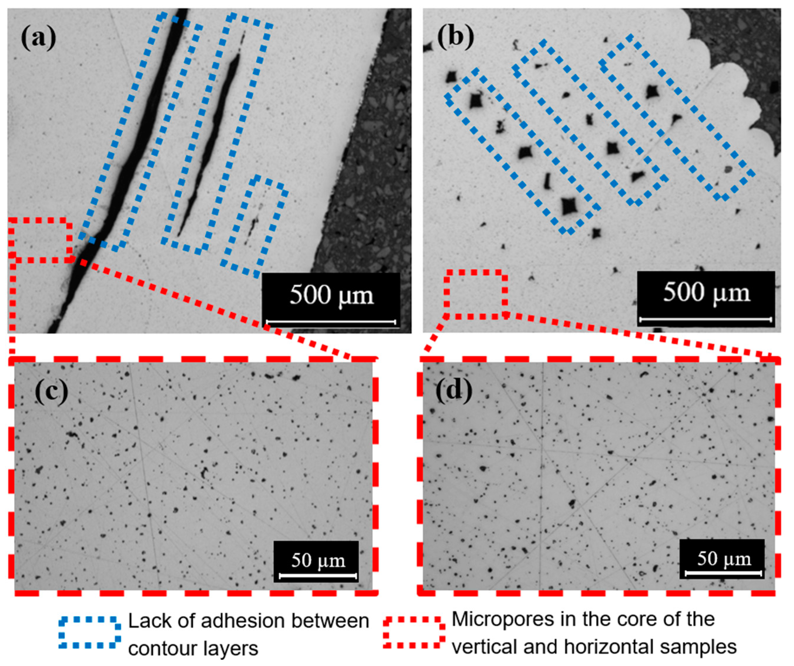
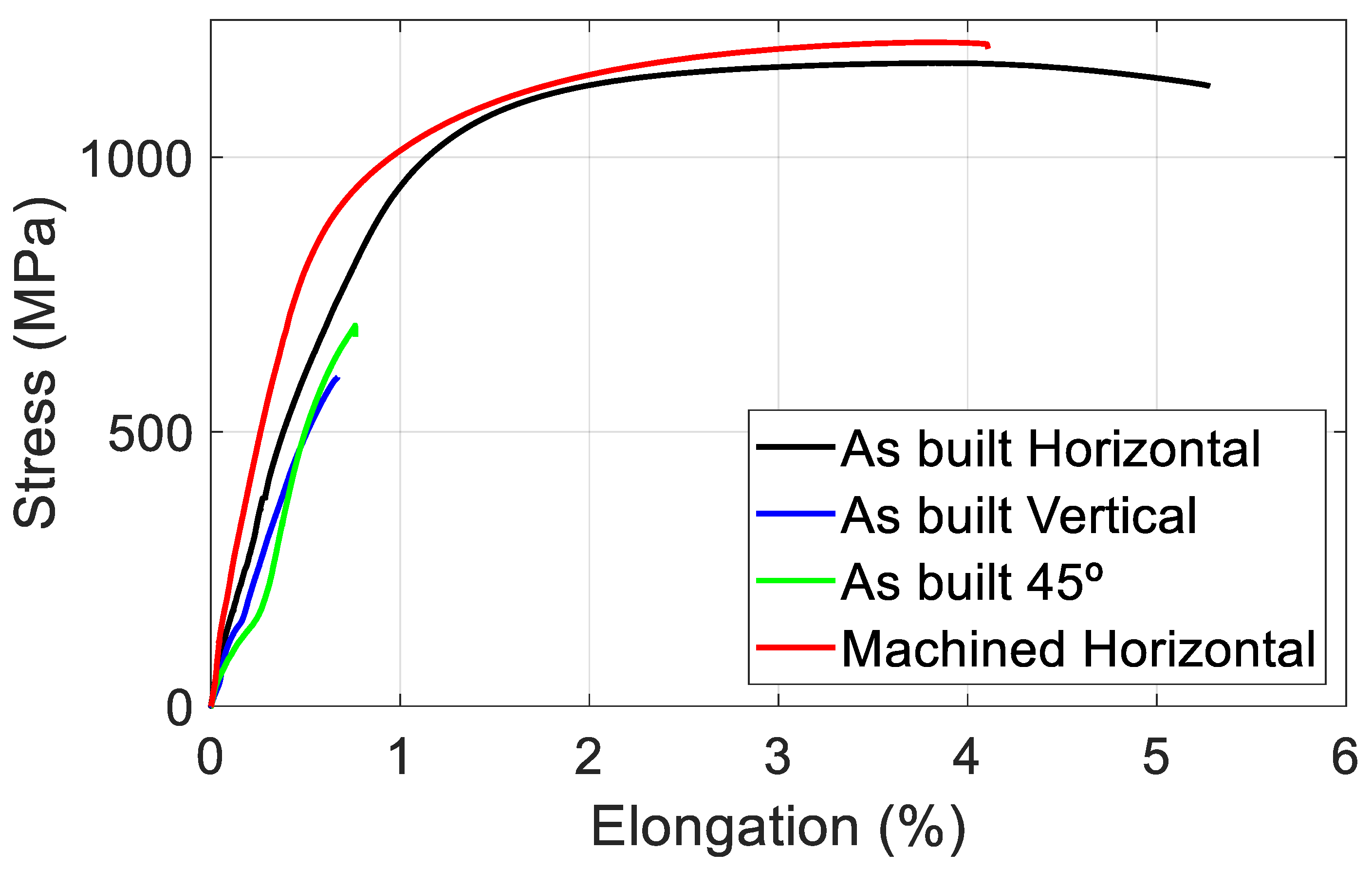
  • The highest tensile strength and ductility were found in horizontal build orientation specimens as reported in other AM technologies. Specimens manufactured with a 45° and vertical orientation achieved only half the value in tensile strength and seven times lower elongation, due to the bad adhesion between layers.
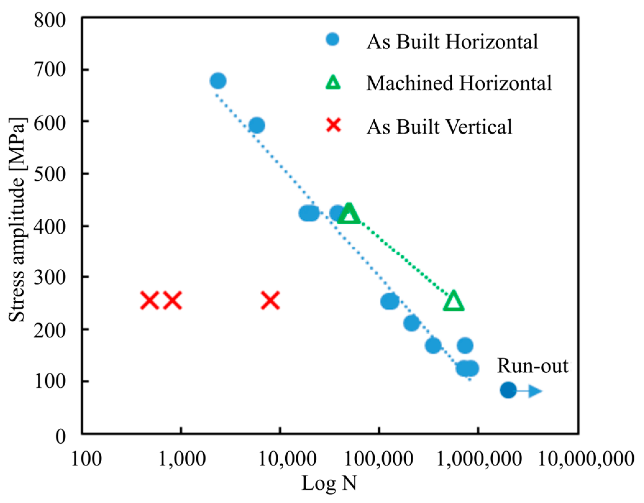
  • The behavior of fatigue was also significantly affected by the building orientation. As in other AM technologies, the highest fatigue strength was found in horizontal build orientation specimens.
  • All cracks were initiated near the surface in the fatigue tests. The fact that machined parts, with smooth surfaces, increased the fatigue life on average two to four times at the tested stress range shows that surface roughness is a major variable affecting the fatigue performance of parts produced by ADAM technology. This also suggests that post-process operations will be key to the manufacture of parts with enhanced fatigue properties
  • The characteristics of ADAM technology make the top part of the fatigue specimens the weakest due to the influence of geometrical distortions and a thinner contour layer at the top compared to the sides of the specimen.
  • In spite of the fact that a higher number of cavities was observed in the contour layer, removing it by a post-process like a turning process does not significantly improve the mechanical behavior of a part; indeed, it seems that this could be counterproductive.
  • However, poor relative density values were achieved. An optimization of the printing stage is expected to produce parts with higher density values. Consequently, an improvement in relative density will increase its mechanical and fatigue behavior.

Author Contributions

Conceptualization, P.J.A., A.Z., I.F. and D.S.; methodology, J.R., A.Z. and D.S.; validation, A.M., I.F. and D.S.; formal analysis, J.R., A.M., I.F. and D.S.; investigation, J.R., A.Z., E.D., A.M., I.F. and D.S.; resources and founding acquisition, A.Z. and P.J.A.; data curation, J.R., A.M., E.D., I.F. and D.S.; writing—original draft preparation, J.R. and D.S.; writing—review and editing, D.S.; visualization J.R., A.M., I.F. and D.S.; supervision, P.J.A. and A.Z.; project administration, P.J.A. and A.Z. All authors have read and agreed to the published version of the manuscript.

Funding

This research was funded by Basque Government: Tknika 025_020, project Frontiers V (code KK-2019/00077) and Ekoprop (KK-2022/00074).

Conflicts of Interest

The authors declare no conflict of interest.

References

  1. Hunt, J.; Derguti, F.; Todd, I. Selection of Steels Suitable for Additive Layer Manufacturing. Ironmak. Steelmak. 2014, 41, 254–256. [Google Scholar] [CrossRef]
  2. Mahmoudi, M.; Elwany, A.; Yadollahi, A.; Thompson, S.M.; Bian, L.; Shamsaei, N. Mechanical Properties and Microstructural Characterization of Selective Laser Melted 17-4 PH Stainless Steel. Rapid Prototyp. J. 2017, 23, 280–294. [Google Scholar] [CrossRef]
  3. Mohamed, O.A.; Masood, S.H.; Bhowmik, J.L. Optimization of Fused Deposition Modeling Process Parameters: A Review of Current Research and Future Prospects. Adv. Manuf. 2015, 3, 42–53. [Google Scholar] [CrossRef]
  4. Galati, M.; Minetola, P. Materials Analysis of Density, Roughness, and Accuracy of the Atomic Diffusion Additive Manufacturing (ADAM) Process for Metal Parts. Materials 2019, 12, 4122. [Google Scholar] [CrossRef]
  5. Campbell, I.; Wohlers, T. Markforged: Taking a Different Approach to Metal Additive Manufacturing. Metal AM 2017, 3, 113–115. [Google Scholar]
  6. Gonzalez-Gutierrez, J.; Arbeiter, F.; Schlauf, T.; Kukla, C.; Holzer, C. Tensile Properties of Sintered 17-4PH Stainless Steel Fabricated by Material Extrusion Additive Manufacturing. Mater. Lett. 2019, 248, 165–168. [Google Scholar] [CrossRef]
  7. Bouaziz, M.A.; Djouda, J.M.; Chemkhi, M.; Rambaudon, M.; Kauffmann, J.; Hild, F. Heat Treatment Effect on 17-4PH Stainless Steel Manufactured by Atomic Diffusion Additive Manufacturing (ADAM). Procedia CIRP 2021, 104, 935–938. [Google Scholar] [CrossRef]
  8. Pellegrini, A.; Lavecchia, F.; Guerra, M.G.; Galantucci, L.M. Influence of Aging Treatments on 17–4 PH Stainless Steel Parts Realized Using Material Extrusion Additive Manufacturing Technologies. Int. J. Adv. Manuf. Technol. 2023, 126, 163–178. [Google Scholar] [CrossRef]
  9. Henry, T.C.; Morales, M.A.; Cole, D.P.; Shumeyko, C.M.; Riddick, J.C. Mechanical Behavior of 17-4 PH Stainless Steel Processed by Atomic Diffusion Additive Manufacturing. Int. J. Adv. Manuf. Technol. 2021, 114, 2103–2114. [Google Scholar] [CrossRef]
  10. Alkindi, T.; Alyammahi, M.; Susantyoko, A.; Atatreh, S. The Effect of Varying Specimens’ Printing Angles to the Bed Surface on the Tensile Strength of 3D-Printed 17-4PH Stainless-Steels via Metal FFF Additive Manufacturing. MRS Commun. 2021, 11, 310–316. [Google Scholar] [CrossRef]
  11. Abe, Y.; Kurose, T.; Santos, M.V.A.; Kanaya, Y.; Ishigami, A.; Tanaka, S.; Ito, H. Materials Effect of Layer Directions on Internal Structures and Tensile Properties of 17-4PH Stainless Steel Parts Fabricated by Fused Deposition of Metals. Materials 2021, 14, 243. [Google Scholar] [CrossRef] [PubMed]
  12. Romano, S.; Nezhadfar, P.D.; Shamsaei, N.; Seifi, M.; Beretta, S. High Cycle Fatigue Behavior and Life Prediction for Additively Manufactured 17-4 PH Stainless Steel: Effect of Sub-Surface Porosity and Surface Roughness. Theor. Appl. Fract. Mech. 2020, 106, 102477. [Google Scholar] [CrossRef]
  13. Sanaei, N.; Fatemi, A. Defects in Additive Manufactured Metals and Their Effect on Fatigue Performance: A State-of-the-Art Review. Prog. Mater. Sci. 2021, 117, 100724. [Google Scholar] [CrossRef]
  14. Bouzakis, E.; Arvanitidis, A.; Kazelis, F.; Maliaris, G.; Michailidis, N. Comparison of Additively Manufactured vs. Conventional Maraging Steel in Corrosion-Fatigue Performance after Various Surface Treatments. Procedia CIRP 2020, 87, 469–473. [Google Scholar] [CrossRef]
  15. Yadollahi, A.; Shamsaei, N. Additive Manufacturing of Fatigue Resistant Materials: Challenges and Opportunities. Int. J. Fatigue 2017, 98, 14–31. [Google Scholar] [CrossRef]
  16. Markforged Material Datasheet. 17-4 PH Stainless Steel. 2022. Available online: https://static.markforged.com/downloads/markforged_datasheet_17-4_ph_stainless_steel.pdf (accessed on 23 September 2023).
  17. Andrzejewski, J.; Mohanty, A.K.; Misra, M. Development of Hybrid Composites Reinforced with Biocarbon/Carbon Fiber System. The Comparative Study for PC, ABS and PC/ABS Based Materials. Compos. B Eng. 2020, 200, 108319. [Google Scholar] [CrossRef]
  18. Markforged Sinter-1 Furnace. Available online: https://www.mark3d.com/en/product/markforged-3d-printers/metal-x-markforged-3d-printer/markforged-sinter-1-furnace/ (accessed on 18 July 2023).
  19. ASTM B09.04 B962; Standard Test Methods for Density of Compacted or Sintered Powder Metallurgy (PM) Products Using Archimedes’ Principle. ASTM International (ASTM): West Conshohocken, PA, USA, 2017. [CrossRef]
  20. Aegerter, J.; Kühn, H.J.; Frenz, H.; Weißmüller, C. EN ISO 6892-1:2009 Tensile Testing: Initial Experience from the Practical Implementation of the New Standard. Mater. Test. 2011, 53, 595–603. [Google Scholar] [CrossRef]
  21. Cho, Y.H.; Park, S.Y.; Kim, J.Y.; Lee, K.A. 17-4PH Stainless Steel with Excellent Strength–Elongation Combination Developed via Material Extrusion Additive Manufacturing. J. Mater. Res. Technol. 2023, 24, 3284–3299. [Google Scholar] [CrossRef]
  22. E466 Standard Practice for Conducting Force Controlled Constant Amplitude Axial Fatigue Tests of Metallic Materials. Available online: https://www.astm.org/e0466-21.html (accessed on 17 July 2023).
  23. Becker, T.H.; Kumar, P.; Ramamurty, U. Fracture and Fatigue in Additively Manufactured Metals. Acta Mater. 2021, 219, 117240. [Google Scholar] [CrossRef]
  24. Concli, F.; Fraccaroli, L.; Nalli, F.; Cortese, L. High and Low-Cycle-Fatigue Properties of 17–4 PH Manufactured via Selective Laser Melting in as-Built, Machined and Hipped Conditions. Prog. Addit. Manuf. 2022, 7, 99–109. [Google Scholar] [CrossRef]
  25. Bajaj, P.; Hariharan, A.; Kini, A.; Kürnsteiner, P.; Raabe, D.; Jägle, E.A. Steels in Additive Manufacturing: A Review of Their Microstructure and Properties. Mater. Sci. Eng. A 2020, 772, 138633. [Google Scholar] [CrossRef]
  26. Rafi, H.K.; Pal, D.; Patil, N.; Starr, T.L.; Stucker, B.E. Microstructure and Mechanical Behavior of 17-4 Precipitation Hardenable Steel Processed by Selective Laser Melting. J. Mater. Eng. Perform. 2014, 23, 4421–4428. [Google Scholar] [CrossRef]
  27. Allegheny Technologies Incorporated Stainless Steel AL 17-4TM Precipitation Hardening Alloy (UNS Designation S17400). 2016. Available online: https://www.atimaterials.com/Products/Documents/datasheets/stainless-specialty-steel/precipitationhardening/ati_17-4_tds_en_v2.pdf (accessed on 23 September 2023).
  28. Sepe, R.; Giannella, V.; Alfieri, V.; Caiazzo, F. Static and Fatigue Behavior of Laser Welded Additively Manufactured 17-4 PH Steel Plates. Procedia Struct. Integr. 2021, 34, 172–177. [Google Scholar] [CrossRef]
  29. Nezhadfar, P.D.; Burford, E.; Anderson-Wedge, K.; Zhang, B.; Shao, S.; Daniewicz, S.R.; Shamsaei, N. Fatigue Crack Growth Behavior of Additively Manufactured 17-4 PH Stainless Steel: Effects of Build Orientation and Microstructure. Int. J. Fatigue 2019, 123, 168–179. [Google Scholar] [CrossRef]
  30. Afkhami, S.; Dabiri, M.; Alavi, S.H.; Björk, T.; Salminen, A. Fatigue Characteristics of Steels Manufactured by Selective Laser Melting. Int. J. Fatigue 2019, 122, 72–83. [Google Scholar] [CrossRef]
  31. Mower, T.M.; Long, M.J. Mechanical Behavior of Additive Manufactured, Powder-Bed Laser-Fused Materials. Mater. Sci. Eng. A 2016, 651, 198–213. [Google Scholar] [CrossRef]
Figure 1. Deposition strategies of the printing stage. (a) Theoretical layer. (b) Macroscopic image of a part layer manufactured by ADAM.
Jmmp 07 00172 g001
Figure 2. Example of support structure in a 17-4 PH SS part. (a) Programmed part. (b) Printed part.
Jmmp 07 00172 g002
Figure 3. Sintering stage. (a) Schematic of the sintering cycle: (1) removal of remaining wax and thermoplastic polymer and (2) diffusion bonding of powder particles. (b) 17-4 PH SS brown part example. (c) 17-4 PH SS sintered part example (18% reduction in size).
Jmmp 07 00172 g003
Figure 4. Thermograms of the commercial filament.
Jmmp 07 00172 g004
Figure 5. Secondary electron images of the powder after TGA: (a) with lower magnification; (b) with high magnification.
Jmmp 07 00172 g005
Figure 6. Surfaces for surface roughness measurements. The arrows indicate the location where the measurements were performed.
Jmmp 07 00172 g006
Figure 7. Geometry of the tensile test specimen.
Jmmp 07 00172 g007
Figure 8. Tensile specimens. (a) As built with 45° inclination. (b) As built vertically. (c) As built horizontally. (d) Oversized horizontal for further machining.
Jmmp 07 00172 g008
Figure 9. Cross-section of tensile specimens. (a) As built vertical. (b) As built horizontal. (c) Zoomed core of the vertical sample. (d) Zoomed core of the horizontal sample.
Jmmp 07 00172 g009
Figure 10. Surface texture produced by different deposition strategies in the axial direction of the specimens. (a) As built with 45° inclination. (b) As built vertically. (c) As built horizontally. (d) Machined horizontally.
Jmmp 07 00172 g010
Figure 11. Geometry of the fatigue test specimen.
Jmmp 07 00172 g011
Figure 12. Surface roughness vs. angle of measured samples.
Jmmp 07 00172 g012
Figure 13. Stress–strain curves of samples built in different orientations.
Jmmp 07 00172 g013
Figure 14. Stress amplitude vs. fatigue life of the three types of specimens: as-built horizontal, machined horizontal and as-built vertical.
Jmmp 07 00172 g014
Figure 15. Cross-section of tensile specimens. (a) As built vertical. (b) As built horizontal, obtained with the SEM after chemical attack.
Jmmp 07 00172 g015
Figure 16. Images of the fractures of samples tested at a stress amplitude of 255 MPa. (a) As built horizontally. (b)As built vertically. (c) Machined.
Jmmp 07 00172 g016
Figure 17. Effect of machining on the fatigue performance of samples built in the horizontal orientation.
Jmmp 07 00172 g017
Table 1. Chemical composition of 17-4 PH SS [16].
CrNiCuSiMn
Amount (%)15–17.53–53–51 max1 max
NbCPSFe
Amount (%)0.15–0.450.07 max0.04 max0.03 maxbal
Table 2. The elastic modulus, yield stress, tensile strength and maximum elongation of tested specimens, and some literature values.
Elastic Modulus
(GPa)
Yield Stress
(MPa)
Tensile Strength (MPa)Maximum
Elongation (%)
As built horizontal137 ± 11851 ± 231125 ± 104.98 ± 0.5
As built verticalab630 ± 540.66 ± 0.15
As built 45°ab660 ± 560.69 ± 0.06
Machined195 ± 16842 ± 571146 ± 193.47 ± 0.65
Metal Extrusion [6]196 ± 22-696 ± 314 ± 1.12
Wrought [27]19676010308
Markforged Reference Values [16]15271011807
a Non-linear shape of Strain–Stress curve. b Failure in elastic region (see Figure 13). - No provided value.
Disclaimer/Publisher’s Note: The statements, opinions and data contained in all publications are solely those of the individual author(s) and contributor(s) and not of MDPI and/or the editor(s). MDPI and/or the editor(s) disclaim responsibility for any injury to people or property resulting from any ideas, methods, instructions or products referred to in the content.

