Optimization of Lightweight Axles for an Innovative Carving Skateboard Based on Carbon Fiber Placement †

Department of Textile Technologies, Technische Universität Chemnitz, Reichenhainer Strasse 31/33,09126 Chemnitz, Germany
*
Author to whom correspondence should be addressed.
†
Presented at the 12th conference of the International Sports Engineering Association, Brisbane, Queensland, Australia, 26–29 March 2018.
Proceedings 2018, 2(6), 253; https://doi.org/10.3390/proceedings2060253
Published: 23 February 2018
(This article belongs to the Proceedings of The 12th Conference of the International Sports Engineering Association)
Abstract
:In 2003, the BMW Group developed a longboard called “StreetCarver”. The idea behind this product was to bring the perfect carving feeling of surf- and snowboarding on the streets by increasing the maneuverability of classical skateboard trucks. The outcome was a chassis based on complex kinematics. The negative side effect was the StreetCarver’s exceptional high weight of almost 8 kg. The main reason for this heaviness was the choice of traditional metallic engineering materials. In this research, modern fiber reinforced composites were used to lower the chassis’ mass by up to 50% to reach the weight of a common longboard. To accomplish that goal, carbon fibers were placed along pre-simulated load paths of the structural components in a so-called Tailored-Fiber-Placement process. This technology allows an angle-independent single-roving placement and leads not only to the reduction of weight but also helps to save valuable fiber material by avoiding cutting waste.

1. Introduction
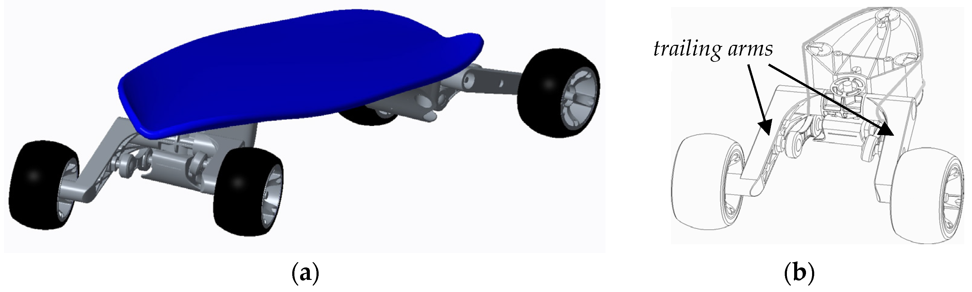
For sports equipment, a weight reduction often resembles an important step towards the optimal product performance. The lower the weight of the equipment, the smaller its influence on the athlete’s performance. Thus, in many cases lightweight design leads to an enhanced user experience. Heavy weight however may limit the gear’s potential capabilities. An example for this is the longboard called “StreetCarver” (see Figure 1a) developed by the BMW Group in 2003. Four-link coupler mechanisms (see Figure 1b) enable adaptive wheel camber angles and the raise of the board’s center of gravity by allowing an especially steep inclination angle of the deck. Therefore, designers had access to a repertoire of original automotive parts deriving from BMW street cars. A theoretical curve radius as low as 60 cm can be achieved at low driving speed, allowing a riding experience similar to carving on snow- or surfboards. This improved carving performance required a significant increase of weight by almost 75% compared to a modern longboard, leading to an unwieldy driving behavior. To unveil the board’s full potential, bulky chassis components had to be redeveloped using methods of lightweight engineering. In a preceding student project, the StreetCarver’s design, kinematics and effective loads on all mounting points were analyzed. Within this work now, the mass of 318 g of the chassis’ trailing arms (see Figure 1b) were optimized by redesigning the arms as a Fiber-Reinforced-Plastic (FRP)-structure. Instead of building that structure from a hand-layup of woven fiber-reinforcement fabric plies, an automated fiber-placement technology called “Tailored-Fiber-Placement” (TFP) was used. To enhance the trailing arms’ lightweight potential, this technology was used to place valuable reinforcement fibers only along simulated stress directions. This helped to achieve an increased manufacturing accuracy of the FRP-structure and an optimal material utilization. Net-shape manufacturing of the fiber-reinforcement structure lead to a minimization of cutting waste [1]. A feasible design approach suitable for composite manufacturing had been developed and was used as a basis for this optimization approach of the TFP-structure of the trailing arms. The new FRP-version was compared with the original arm in a Finite-Element-Analysis (FEA). The goal was to reduce weight by 50%.
2. Materials and Methods
2.1. Analysis of the Original Trailing Arm
To understand the functionalities of all components, a model of the BMW StreetCarver was disassembled, re-engineered in a CAD model and was weighed part by part. The following relevant assembly and component weights were measured (Table 1).
All main components consist of die-cast aluminum, leaving plenty of scope for material-based lightweight engineering. Alone a theoretical substitution of this alloy (density ≈ 2.70 g/cm3) by carbon-fiber-reinforced-plastics (CFRP) (density at 50% fiber volume content (FVC) ≈ 1.48 g/cm3) within the existing design would lead to a weight reduction of 45%, if mechanical properties remain on a similar or improved level. However, the use of CFRP only makes sense for structures primarily showing uniaxial stress. Within the design of the StreetCarver the two trailing arms depict the largest parts suitable for such a material substitution. To achieve a successful FRP-structure it is crucial to understand the specific load cases affecting a component. Based on the CAD-Model, a multi-body-analysis of the board’s kinematics was carried out. For this research only the presumed maximum load, described by a loading case occurring when driving through a pothole, were considered to keep the model as simple as possible. By this, influences of variations in the TFP-structure can be detected more easily. Therefore, a weight force of 3G was applied on the system rider and board, consisting of 7960 g board and a rider of 160 kg. This resulted in the bearing loads on the trailing arm displayed in Table 2.
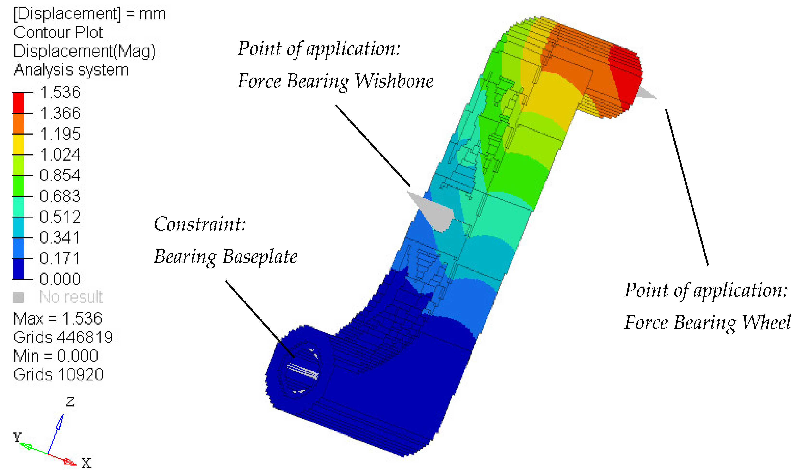
These values were then basis to evaluate the original design of the trailing arm in a Finite-Elements-Analysis (FEA) carried out with the simulation tool Altair HyperWorks and its native solver OptiStruct. This software has found a broad application in all fields of structural analysis. As the global deflection of the component was the only parameter relevant for the dimensioning of the new FRP-model, a voxel-mesh with an element size of 0.5 mm was generated to minimize calculation effort. The housing of the baseplate bearing was constraint in all 6 directions. A maximal deflection of 1.5 mm (see Figure 2) was determined at the bearing housing of the wheel axis.
2.2. FRP-Appropriate Design
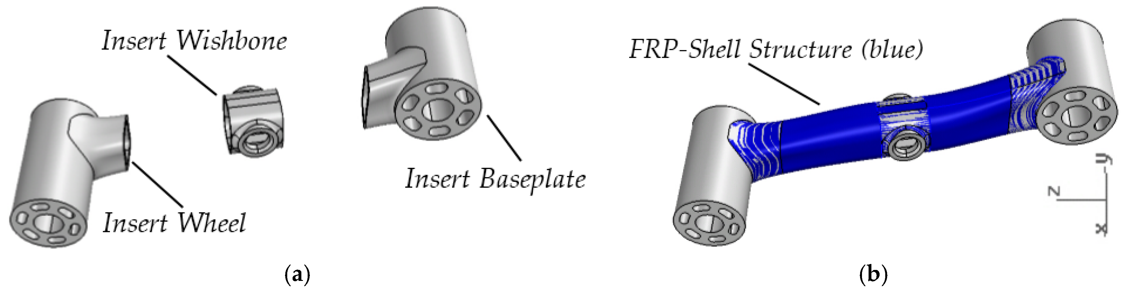
A component made of FRP requires a design approach appropriate for material, manufacturing method and load introduction. The FRP-structure of the trailing arm that was developed in this study will be manufactured in a vacuum resin infusion process. For this, the rib design of the current trailing arms was neither applicable nor advantageous. This process required a shell structure that can be represented by a one-sided mold entirely. Ideally an anisotropic FRP-structure is used for load transmission only, whereas for load introduction additional elements made of isotropic materials are integrated into this structure. Specifically, for these demands a new design approach of the trailing arm was taken, consisting of the FRP-structure and integrated insert elements for the connection to baseplate, wishbone and wheel (compare Figure 3). These elements were designed out of Selective-Laser-Sintered (SLT) TiAl6V4-Material and achieved an overall weight of 154 g. All connecting points remained at their original places so that the board’s kinematics did not change. The design process of inserts and FRP-shell geometry shall not be referred to any further at this point.
2.3. Optimization of the FRP-Shell Structure
Fiber reinforced plastics have found a broad use in lightweight engineering. When it comes to designing structures containing variable, angle independent fiber orientations, conventional simulation tools offer only limited capabilities. To fully exploit anisotropic properties of FRP-structures, automated fiber laying techniques such as TFP are necessary. Only when reinforcement fibers are oriented in the direction of tension, their high strength can be used effectively. A variation of 10 degrees between fiber orientation and load direction reduces strength by about 20% of the maximum [2]. A FE-simulation model of a TFP-based part has to take this into consideration. Conventional software tools are prepared to simulate a laminate based on stacking of fabric plies. While such a ply-based modelling approach only deals with constant material directions within a single ply, a model suitable for TFP-based structures has to be able to change material directions throughout a ply (rather: roving laying path). Both laying paths and material directions have to be derived from the 2D-TFP-pattern used for the manufacturing of the TFP-preform. The software tool TACO (Tailored Composite Design Code) developed at DLR, Institute of Composite Structures and Adaptive Systems, offers capabilities of adapting fiber orientations in a FE-model to a TFP-pattern [3]. A software tool called AOPS (Advanced Optimization for Principal Stress) offering advanced capabilities has been developed and applied successfully at Institut für Polymerforschung Dresden e.V. (IPF). Based on an analysis of main directions of tension within a structure, ideal TFP patterns and material orientations can be determined and projected on a manufacturable 2D-net-shape preform contour [4]. As all these solutions are not integrated into conventional FE-simulation software and are primarily accessible for projects with scientific background, a method using the commercially available tool Altair HyperWorks/OptiStruct will be investigated.
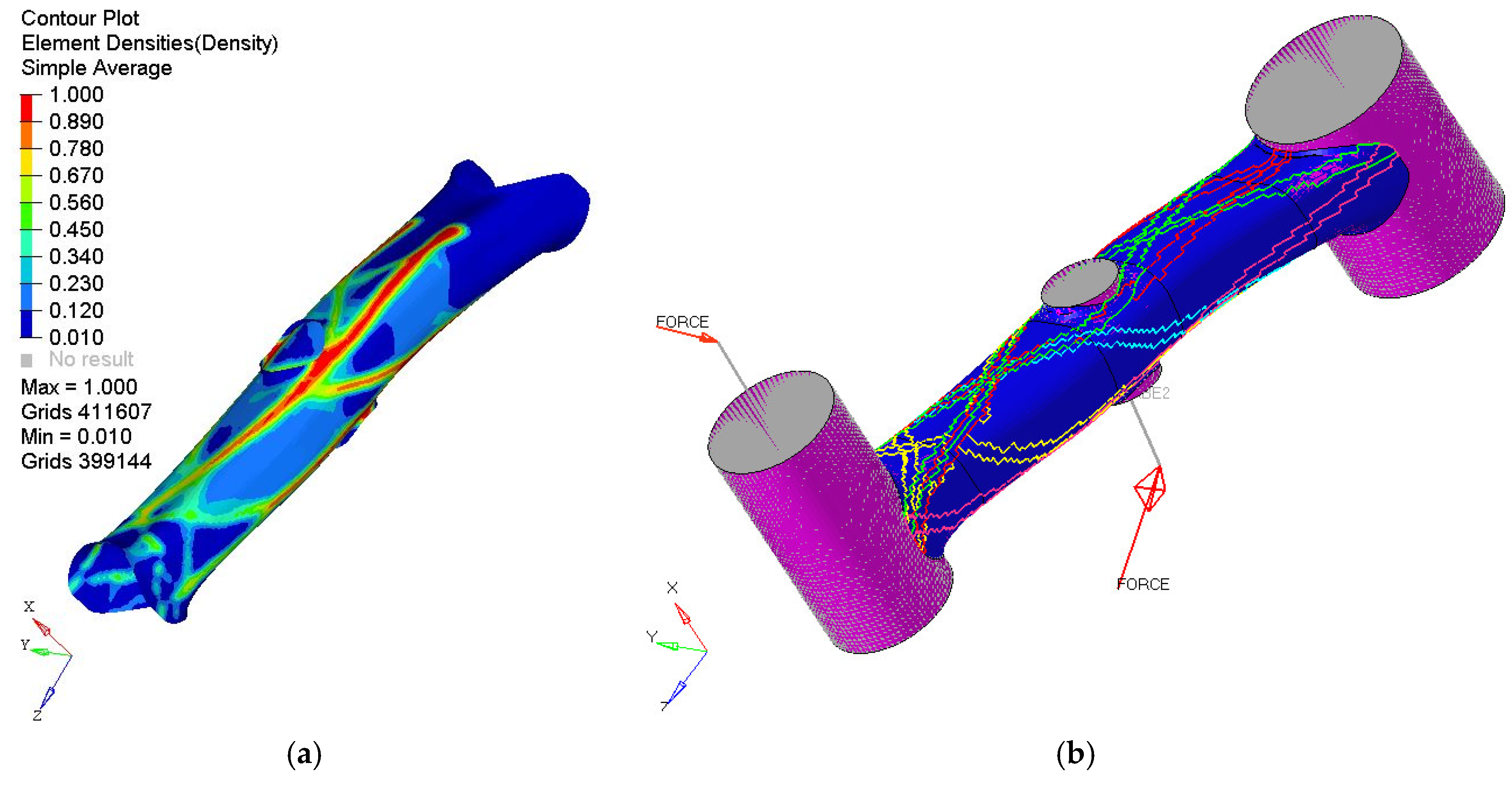
Therefore a modelling approach described by Spickenheuer [4] was applied to the design process of the trailing arm’s TFP-pattern. As in every composite optimization process the goal is to determine where and how much fiber material is needed as well as which direction fibers have to be oriented to. Step one in this approach here was to define the location and direction of potential roving paths along the trailing arm. A topology optimization was run on the FRP-shell structure with 50 iterations. The results are displayed in Figure 4a. Additionally, an analysis of main directions of tension then helped to determine the ideal fiber orientation within the TFP-pattern. The following criteria were considered in the topology optimization.
- material: CFRP (isotropic, as only location of material is needed), 2 mm max. thickness
- load cases: equal to analysis of original trailing arm; symmetric application (to z-axis) of forces to ensure the use on both sides of the longboard
- optimization constraint: Displacement at bearing housing of wheel axis <1.5 mm
- objective: minimize mass
The results showed a clearly distinct framework structure, which was a good foundation for roving placement. A cross-comparison with the main directions of tension (not displayed) supported the subjective interpretation regarding fiber orientation, the tensions followed the framework paths of the optimization.
2.4. Design of the TFP-Pattern
The arising framework structure showed a relatively constant width of 5 mm. To achieve these dimensions in the TFP-process, a 50 k 3300 tex C-fiber roving was chosen. At a processing width of 5 mm a thickness of 0.5 mm per layer can be achieved with this roving. With a desired fiber-volume-content of 50% an overall thickness of 1 mm per layer of the composite structure can be assumed. The tensile strength of this composite is 3.0 GPa in fiber direction. Thus, to reach a thickness of 2 mm within the TFP-pattern, 2 rovings need to be embroidered on a ground fabric. For this ground material, a woven carbon fiber fabric with a thickness of 0.1 mm was chosen, leading to a final composite thickness per layer of 0.2 mm. Due to possible warping effects a symmetrical CFRP-structure was desirable. For this reason, two mirrored preforms have to be manufactured and finally stacked before the molding process.
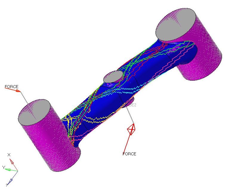
Based on these requirements and the result of the topology optimization a composite structure representing the TFP-pattern was modelled within Altair HyperWorks. To adapt the material orientation to the roving paths, the element orientations of every element representing a roving were aligned to vectors. These vectors again represented the fiber orientation of an area of a roving path with a deviation of less than 5 degrees. Deviations were measured in a CAD program separately. At intersection points, a mean of orientation angles was applied. The embroidery ground material was assigned a ±45 degree orientation. The arising TFP-roving-structure is displayed in Figure 4b. This model was then simulated in a linear static FE-analysis again, using the same load cases as before. Two variations of the TFP-structure’s thickness were investigated, one with 2 mm and another one with 4 mm.
3. Results
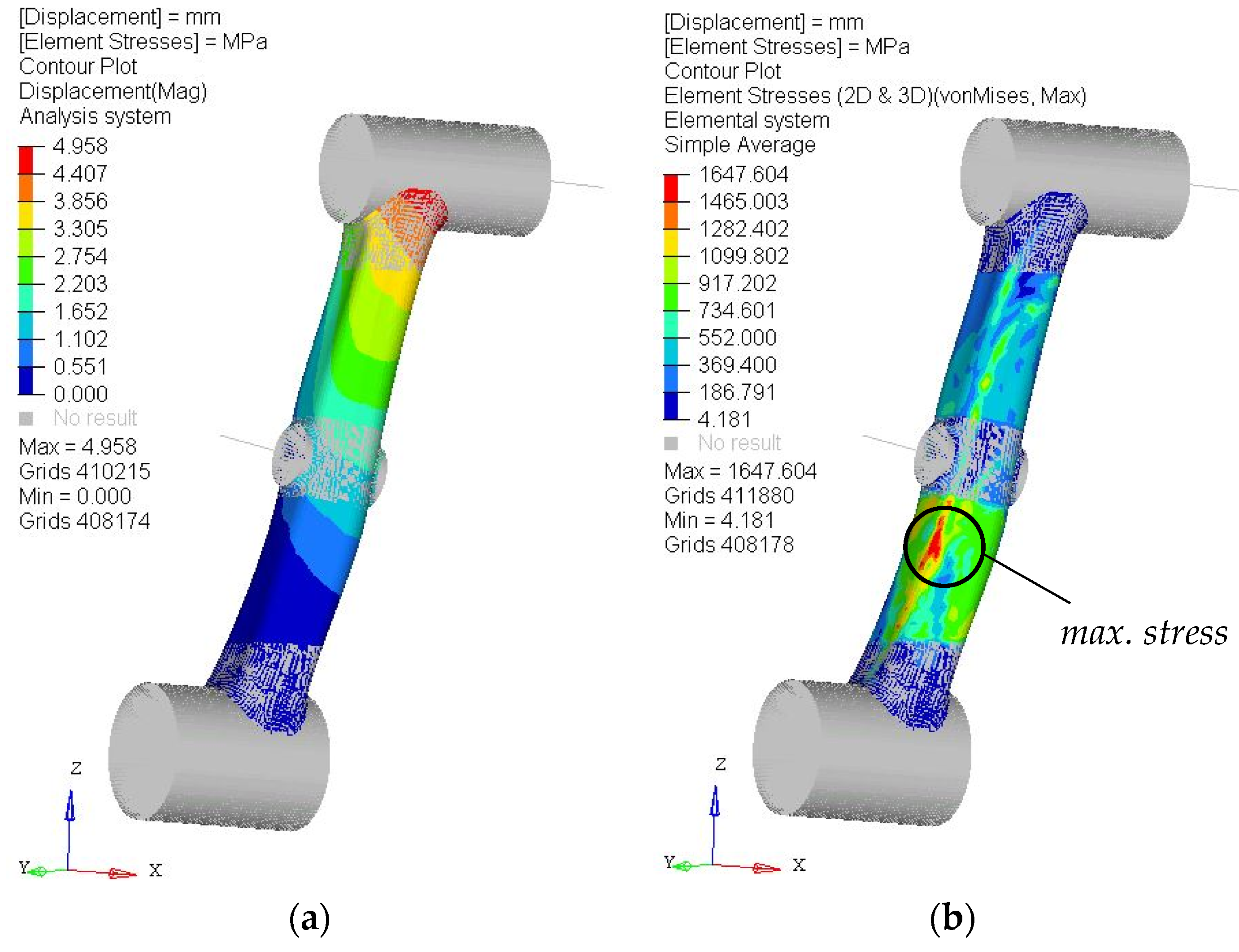
As seen in Figure 5a, the maximal displacement of the 2 mm structure was close to 5 mm. Compared to the original design of the trailing arm this was more than 3 times higher than the initial value. Yet when looking at the element stresses (Figure 5b) it became visible that the max. tensions of 1.65 GPa are just above 50% of the material’s tensile strength. This resulted in a safety factor close to 2, a fairly high value in the field of lightweight engineering. The weight of the structure was 16 g. The model containing the 4 mm TFP-structure lowered the deflection to 2.75 mm and stresses to 1.15 GPa at a weight of 26 g. In addition, with the weight of the three inserts, the newly designed trailing arm reached a weight of 169 g respectively 179 g. This lead to an overall weight reduction of 48% (45%).
4. Discussion
A significant weight reduction of almost 50% of the original trailing arm was achieved with this first iteration of the TFP-pattern. The results have to be seen as a compromise between ideal material utilization and the component’s displacement. While the 2 mm version may be a good solution in terms of lightweight design, a potential (negative) influence on the StreetCarver’s kinematics due to a deflection more than 3 times as high as in the original design has to be considered. Adjustments to the TFP-pattern within highly deformed zones around the bearing housing of the wheel axis may lead to a stiffer design with an only slight increase of weight. Looking at the effective stresses, areas around roving intersections had to be interpreted carefully. Due to the fact that every element within the FE-mesh could have been assigned one single material orientation only, fiber orientations were not represented ideally in some areas. Small areas containing elements with regular global material orientation were enclosed by roving paths. These issues lead to stress peaks appearing in areas where they were not expected to be. This effect accounted for the elements showing the highest stresses in Figure 5b. Also stresses in areas containing only ground fabric had to be looked at critically. As local tensions may not be aligned with fiber orientations, the tensile strength can be lower than the maximal value. This may result in the components failure and would have to be looked at closely in a failure analysis appropriate to fiber composite material. To avoid potentially critical stresses, the ideal fiber orientation of the woven ground fabric should be determined in an additional laminate optimization. Also adding a thin layer of foam plastic material as a sandwich core in the middle layer of the composite structure can be a conceivable solution.
5. Conclusions
Applying TFP-technology to components of sports equipment offers a tremendous potential of weight reduction and material saving. Both process automation and significantly improved material utilization are important factors to raise a product’s performance. Yet, the design of the TFP-pattern requires specialized software tools for and precise and work time efficient simulations. As seen in this research, desired functions are barely integrated into conventional FE-software, leading to limited reliability of calculated results when more complex structures are being analyzed. In the future, this simulation approach will be improved and more specific load cases added to the model. Further variations of TFP-patterns will be developed until a feasible design of the StreetCarver’s trailing arm is achieved.
Acknowledgments
This work was performed within the Federal Cluster of Excellence EXC 1075 “MERGE Technologies of Multifunctional Lightweight Structures” and supported by the German Research Foundation (DFG). Financial support is gratefully acknowledged.
Conflicts of Interest
The authors declare no conflict of interest.
References
- Crothers, P.J.; Drechsler, K.; Feltin, D.; Herszberg, I.; Kruckenberg, T. Tailored fibre placement to minimise stress concentrations. Compos. Part A Appl. Sci. Manuf. 1997, 28, 619–625. [Google Scholar] [CrossRef]
- Mattheij, P.; Gliesche, K.; Feltin, D. Tailored Fiber Placement—Mechanical Properties and Applications. J. Reinf. Plast. Compos. 1998, 17, 774–786. [Google Scholar] [CrossRef]
- Temmen, H.; Degenhardt, R.; Raible, T. Tailored fibre placement optimisation tool. In Proceedings of the 25th International Congress Aeronautical Science (ICAS), Hamburg, Germany, 3–8 September 2006; Volume 4, pp. 2462–2471. [Google Scholar]
- Spickenheuer, A. Zur Fertigungsgerechten Auslegung von Faser-Kunststoff-Verbundbauteilen für den Extremen Leichtbau auf Basis des Variabelaxialen Fadenablageverfahrens Tailored Fiber Placement. Ph.D. Thesis, Technische Universität Dresden, Dresden, Germany, 2014. [Google Scholar]
Figure 1.
(a) CAD Model of the original trailing arm of the StreetCarver; (b) chassis including trailing arms.
Figure 1.
(a) CAD Model of the original trailing arm of the StreetCarver; (b) chassis including trailing arms.

Figure 2.
Static deflection of original trailing arm [mm].

Figure 3.
Design of inserts (a) and FRP shell structure (b).

Figure 4.
(a) Topology optimized structure of FRP-shell model; (b) TFP-roving-structure assigned to FE-model.
Figure 4.
(a) Topology optimized structure of FRP-shell model; (b) TFP-roving-structure assigned to FE-model.

Figure 5.
Linear static analysis of CFRP-structure containing a 2 mm TFP-structure; (a) element displacement [mm]; (b) element stresses [MPa].
Figure 5.
Linear static analysis of CFRP-structure containing a 2 mm TFP-structure; (a) element displacement [mm]; (b) element stresses [MPa].


Table 1.
Comparison of weight (measured): StreetCarver and conventional Longboard.
| Share | Number of Pcs. | Weight in g | |
|---|---|---|---|
| StreetCarver | Longboard | ||
| Deck | 1 | 2400 | 2900 |
| Truck | 2 | 1640 | 430 |
| Thereof trailing arm | 4 | 318 | - |
| Wheel | 4 | 570 | 205 |
| Total | 7960 | 4580 | |
Table 2.
Bearing loads on trailing arm, loading case “Pothole” (see also Figure 4b).
Table 2.
Bearing loads on trailing arm, loading case “Pothole” (see also Figure 4b).
| Point of Application | Direction | Force [N] |
|---|---|---|
| bearing wheel | X | −624 |
| Y | −1695 | |
| Z | −313 | |
| bearing wishbone | X | −1354 |
| Y | 3390 | |
| Z | −5337 |
Publisher’s Note: MDPI stays neutral with regard to jurisdictional claims in published maps and institutional affiliations. |
© 2018 by the authors. Licensee MDPI, Basel, Switzerland. This article is an open access article distributed under the terms and conditions of the Creative Commons Attribution (CC BY) license (https://creativecommons.org/licenses/by/4.0/).
Share and Cite
MDPI and ACS Style
Fleischmann, M.; Ehemann, C.; Kaufmann, J.; Cebulla, H. Optimization of Lightweight Axles for an Innovative Carving Skateboard Based on Carbon Fiber Placement. Proceedings 2018, 2, 253. https://doi.org/10.3390/proceedings2060253
AMA Style
Fleischmann M, Ehemann C, Kaufmann J, Cebulla H. Optimization of Lightweight Axles for an Innovative Carving Skateboard Based on Carbon Fiber Placement. Proceedings. 2018; 2(6):253. https://doi.org/10.3390/proceedings2060253
Chicago/Turabian StyleFleischmann, Marc, Conrad Ehemann, Jörg Kaufmann, and Holger Cebulla. 2018. "Optimization of Lightweight Axles for an Innovative Carving Skateboard Based on Carbon Fiber Placement" Proceedings 2, no. 6: 253. https://doi.org/10.3390/proceedings2060253