Path to an Integrated Modelling between IFC and CityGML for Neighborhood Scale Modelling


1
Engineering Cluster, Singapore Institute of Technology, 138683 Singapore, Singapore
2
EDF Lab Singapore, 10 Woodlands Avenue 8, 738973 Singapore, Singapore
*
Author to whom correspondence should be addressed.
Urban Sci. 2017, 1(3), 25; https://doi.org/10.3390/urbansci1030025
Submission received: 8 May 2017
/
Revised: 2 August 2017
/
Accepted: 10 August 2017
/
Published: 11 August 2017
(This article belongs to the Special Issue Urban Heat Island and Mitigation Technologies—Impact and Mitigation)
Abstract
:Planning of the built environment requires two-levels of planning process, city/neighborhood-scale and building-scale levels. At the city/neighborhood-scale, Geographic Information System (GIS) is commonly used with CityGML as its open-source 3D format. Meanwhile, for building-scale, Building Information Modelling (BIM) is used, and Industry Foundation Classes (IFC) format is its open-source file format. Both technologies work on different data formats and data exchanges. The research is focusing on ways of exchanging information and bringing together CityGML and IFC. With local context input, the methodology could be considered as a framework to parametrically manage the information related to energy, environment, security, etc. In this project, two use cases were developed, such as visualization for a web application. Autodesk Revit and Graphisoft Archicad were used in developing the building models as a prototype for the transformation testing. The transformation system was developed using Feature Manipulation Engine (FME), by Safe Software. FME allowed us to restructure the data model (IFC) and transformed it to the destination data format (CityGML). The test results showed that from detailed BIM models, CityGML format, as well as a Sketchup file, could be generated. These models can be imported to web visualization applications for urban energy modelling.
1. Introduction
Planning of the built environment requires at least two different levels of planning process and modeling. They can be categorized as city/neighborhood-scale and building-scale. Urban planners and urban designers usually develop the city/neighborhood-scale model, while building design teams such as architects and/or building developers develop building-scale models. The commonly used technologies for both scales are Geographic Information System (GIS) and Building Information Modeling (BIM) respectively. Both technologies work on different data formats and data exchanges.
GIS can use the CityGML format as its open-source 3D file format, while BIM uses IFC file format. Current problems lie on different approaches and underlying standards, i.e., IFC and CityGML, for building and neighborhood-scale models respectively. Semantics, a field related to the mathematical definitions on how programs behave, using logic and set theory, used as a tool for language design for expressing design choices, understanding language features and how they interact [1] and spatial representation are very different in both systems, which make data sharing and data exchange complicated.
The integration of city/neighborhood-scale and building-scale modeling is important as the city-level model provides context for building-level models on how the surrounding environment affects its design. Meanwhile, building-scale models will provide a rich city-scale model [2].
Recently, researchers have started to look into the approach for GIS, neighborhood-scale 3D (CityGML format) and BIM (IFC format) modelling integration. Extensive efforts were put into building model extensions, such as IFC4 and CityGML ADE, to realize meaningful integration. A unified model is under development for integrating the two standards; but the combination sacrifices the semantic and cannot be applied to the existing models. The key of the integration is merely data conversion.
In this project, a practical approach in a local Singapore context is being used to build a simple and straightforward transition framework. The research approach is using case study models and the research focus is on understanding and defining the rules of data semantics for seamless geometric transformation and semantic matching between both formats. The deliverable of this project can be immediately used and easily adapted by the architect and building modelers who have limited knowledge of data semantics and data interoperability.
The objective is to propose a spatial Extract, Transform and Load (ETL) workflow for the effective integration of IFC, CityGML and Sketchup. Several ETL workflows are designed to define adequate transformations between IFC and CityGML format at different Levels of Detail (LOD) and between IFC and Sketchup format. It provides solutions for practical applications like visualization for a web application, input models of urban microclimate modelling or input models for building energy consumption simulation.
2. Background and Literature Review
2.1. Introduction to IFC and CityGML
CityGML is a common information model and XML-based encoding for the representation, storage, and exchange of virtual 3D city and landscape models. It is realized as an opened data model and implemented as an application schema (Schema is the organization or structure of a database. The term is often used in relational databases and object-oriented data bases [3]) for the Geography Markup Language 3 (GML3), the extendible international standard for spatial data exchange issued by Open Geospatial Consortium (OGC) and ISO/TC211 Geographic information/Geomatics [4]. It provides a standard model and mechanism for describing 3D objects in relation to their geometry, topology, semantics and appearance generalization of hierarchies between thematic classes, aggregations, relations between objects, and spatial properties [5,6]. CityGML defines five levels of detail (LOD), which the requirements are shown in Table 1 [7].
IFC is defined as an object-based file format oriented specification for exchanging, sharing and re-using information throughout the building industry’s life cycle. It is an open file format developed and maintained by International Alliance for Interoperability since 1995 [5]. IFC aims to specify a common language for building industry technology that increases productivity, improves communication, shortens building delivery time, lowers construction cost, and improves quality throughout building life cycle from design stage to operation and maintenance life cycle of building. It is used to assemble computer-readable models that contain data elements that represent parts of buildings and their relevant information [6,8].
2.2. Literature Review
A number of studies focus mainly on methods of exchanging information to integrate CityGML and IFC. There are two-known approaches in CityGML-IFC integration. The first is to achieve integration through Application Domain Extensions (ADEs) as presented by Bahu and Nouvel [9] or Kolbe [8].
Presented at the Geospatial World Forum by Bahu and Nouvel, [9] Energy ADE for CityGML was developed as an urban energy representation file format extension that offered data exchange and interoperability possibilities between urban energy stakeholders and tools, through a participative development process. The ADE is an extension of the CityGML model for specific application domains, the formal specification in separate XML schemas referencing the CityGML schemas. A structured Energy ADE core and three modules (construction and material, occupancy, energy and systems) were developed; the modules can be potentially used and extended in other fields and application. Some of the applications and test cases are i.e., heating demand calculation, dependencies urban form/energy demand and microclimate studies.
Starting from the observation of the shift in spatial modelling with geometric/graphics-oriented models to representation of well-defined objects with their properties (spatial and graphical), structures and interrelationships, Kolbe [10] considered the CityGML as a base information model for virtual 3D city models. With this CityGML model, a specific Application Domain Extensions (ADE) could be added to provide extra specific information as additional spatial and non-spatial attributes, and/or additional relations/associations. Some issues resulting of the CityGML implementation were, among other things, the files size, the complex data model, geometric model issue and issue of XLinks. Finally, Kolbe proposed the CityGML as a source for the generation of 3D visualization as the result of a portrayaling (Portrayaling, in simplest form, is 1-to-1 conversion of geometry and appearance data to a 3D graphics format including its coordinate transformations [10]) process applied to a CityGML model.
The second approach is through unidirectional transformation of IFC building models into CityGML models. The van Berlo and de Laat’s paper [11] approached the issue of integration and synergy of both GIS and BIM environments through the creation of a CityGML extension for IFC data, called the GeoBIM extension, implemented in the open source BIMserver. The result was then presented in a XLM Schema file (XSD). The issues found during the development and testing were geometric issues, excessive file size and the restriction of LOD export (LOD4 only).
El Mekawy, et al. [5] conducted a study developing unidirectional directional transformation approach from an IFC model to a CityGML model through schema matching and mapping operations. The entities and attributes of an IFC model were matched to a CityGML model schema. The study categorized three matching levels; i.e., “full (direct)” match, “partial” match and “no” match. In addition, the semantic meanings of different building entities were also studied to understand and to identify any potential loss of information in the transformation process. In conclusion, typically, the CityGML objects are partially matched with IFC model schema, which required additional information or complex processing and it could not be easily automated.
Donkers [12] developed a methodology for the conversion of LOD3 building model in CityGML format. The conversion was based on the extraction and mapping of IFC semantics to CityGML semantics, followed by a geometric generalization, which extracted the exterior shell using a transformation based on Boolean and morphological operations. Finally, it ended with semantic and geometric refinements, which optimized the model for analyses. The prototype implementation showed the effectiveness of the methodology and its limitation due to the information missing in IFC’s semantic.
El-Mekawy, et al. [13] proposed Unified Building Model (UBM) approach that integrated both data of CityGML and IFC models. UBM was developed from the superset concept of mathematics in the 1970s [14]. This superset model was widely used in the software engineering field in the 1990s [15]. It contains all the features and objects form both IFC and CityGML. They proposed a reference ontology (Ontology is defined as a common vocabulary for researchers who need to share information in a domain. It includes machine-interpretable definitions of basic concepts in the domain and relations among them. [16]) for both standards as the intermediate broader terminology. As the start, their approach was to collect all classes of both models while eliminating their relationships and then, rebuilt them using Unified Modelling Language (UML). In terms of limitation, the proposal only studied the building models of IFC and CityGML. The conversion processes were not built or verified by ontology tool [8,13,14].
Xun, et al. [17] proposed the concept of City Information Modeling (CIM) as an information integrating framework for BIM and GIS models, comparing and mapping the data schema behind each of them. They tried to build this CIM based on El Mekawy’s UBM. They unified the classification rule of IFC and CityGML according to the function of the city. They divided the IFC and CityGML models in five classes, which were building, transportation, city furniture, Mechanical, Electrical and Plumbing (MEP) and water body. They established mapping relationship between CityGML, BIM and CIM into these five new classes. In parallel, they proposed in order to unify the classification criterion of IFC and CityGMl, to use OmniClass as a classification structure for CIM.
Yu and Teo [18] studied the generation of CityGML LOD models from BIM/IFC models by dividing geometric conversion into calculating node points’ coordinates and editing geometric information, followed by attribute conversion. They also simplified the LOD 4 model to generate different LOD models. However, they have problems with details appearances and are unable to simplify their models automatically.
Geiger, et al. [19] had an approach to integrate an IFC model with a CityGML model through semantic and geometric generalization of IFC models. It was developed as prototype in the IFCExplorer software. The first step is to generate an Intermediate Data Model using the ExtrusionBaseModel considering only relevant building elements. Each building element that was considered for extrusion was represented by its footprint in order to get a uniformed geometric base. Extrusion containers were therefore calculated based on these footprints. Additionally, extrusion containers for building stories are generated. The ExtrusionBaseModel including the extrusion containers was the basis for all further transformations. Tests had been carried for simple house models and the method should be tested on more complex building.
Amirebrahimi, et al. [20] approached the integration of GIS and BIM through a data model to assess the damage of building due to flooding. They designed a conceptual data model illustrating the required concepts and their relationships by using a UML class diagram to develop and to present the data model. They tested the data model on a case study, using a house model exported to an IFC file. For extracting geometry, they converted the IFC elements to ESRI geodatabase using the ArcGIS Interoperability Extension. The attributes and relationships between elements were obtained from an exported XML version of the IFC file and combined them with their geometry using a unique identifier of IFC elements. Their method for integration of BIM and GIS models at data level could facilitate comprehensive assessment and 3D visualization of building damages costs. Their data model was designed for a particular hazard and construction type; further work could be considered to extent the method to other types of buildings and events. Another study on the integration between BIM and GIS models is by Karan, et al. [21]. The study used semantic web technology, which methodology comprised of ontology construction, semantic integration through interoperable data formats and standards, and query of heterogeneous information sources. Kang and Hong [22] proposed a BIM/GIS-based information Extract, Transform and Load (BG-ETL) architecture, which separated the geometrical information and its relevant properties. The results showed benefit in terms of reusability and data processing cost. However, they were less beneficial in terms of flexibility and extensibility of data schema.
Deng, et al. [23] developed mapping rules between IFC and CityGML using an instance-based method and designed a reference ontology and CityGML ADE for schema mediation. The testing of their method showed a proper building component’s geometric transformation and the conservation of the semantic information from IFC to CityGML. The study was limited in terms of its geometry, as only three types of geometric construction in IFC were considered for the transformation.
On the afore-mentioned studies on data transformation and integration, the approaches that they demonstrated worked within the defined circumstances and very specific cases and situations, as summarized in Table 2.
In this project, an effective ETL workflow for the integration of IFC, CityGML and Sketchup was proposed. Adequate transformations’ workflow between IFC and CityGML models at different Levels of Detail (LOD) and between IFC and Sketchup were created. The process of integrating IFC and CityGML/Sketchup is defined based on the ETL workflows and it could be generalized to offer the user the flexibility to develop his own data mapping. This demarcated our approach from others as it offers flexibility of uses and does not required extensive specialized problem software.
3. Methodology
To achieve this research work objective, three use cases were developed, including visualization for a web application, input model of urban microclimate modelling as in SketchUp format and input model for building energy consumption simulation, as summarized in Figure 1.
Autodesk Revit 2016 and Graphisoft Archicad 20 were used in developing the building models as prototype for the transformation testing. Three apartment building models have been developed to be used as prototype. The transformation system has been developed by using Feature Manipulation Engine (FME) 2016.1, by Safe Software. By using FME, a workflow has been designed to restructure the data model (IFC) and transform it to the destination data format (CityGML or Sketchup).
The BIM models are graphically represented and detailed such as geometric information like size, volume, shape, height, orientation and non-geometric information such as quantity and performance data can be read directly from the models, see Figure 2. The site of the models was not represented as it has not been surveyed by the students.
3.1. IFC Conversion
To export the building models, in Revit 2016, an FME plug-in to Revit was added, providing an extended version of the Revit IFC exporter. The new exporter offers some pre-built setups to choose from, but in this study, a customized setting has been used to preserve some data in IFC for the later transformations.
The IFC 2 × 3 Coordination View 2.0 was choosen, as it is the default certified version of export, and the latest version is generally supported by other systems. It is the format based on the IFC 2 × 3 schema and the newer Coordination View 2.0 model view definition.
The space boundaries 2nd level was choosen as it considered the material of the building element and the adjacent spaces behind it, providing thermal values among others. This data would be consider in the later transformation IFC to CityGML LOD3. The export 2D plan view elements has been selected, as the Floor plan data view was necessary for the IFC to Sketchup transformation. All properties have been selected as in the IFC to CityGML LOD3 transformation the properties and schedules were used to extract the material data of the walls.
The use of coarse tesselation for some Boundary Representation (BReps) and profiles has been selected to decrease the file size. The IFCSITE elevation/location was checked for better geo-referencing. Store IFC Global Unique Identifier (GUID) in an element parameter after export was used in Revit to generate in IFC GUID number in the wall schedule. It allowed to link several data file in xls format using this IFC GUID as a common primary key. Meanwhile, for Archicad 20, the standard built in IFC converter have been used.
3.2. Transformation Tool—Feature Manipulation Engine (FME)
In this study, transformation system was developed by using Feature Manipulation Engine (FME) version 2016.1 developed by Safe Software. The Feature Manipulation Engine (FME) is a platform that streamlines the translation of spatial data between geometry and digitals formats in a process called spatial extract, transform and load (spatial ETL). This process has the capabilities of extracting the data from its source, transforming it as required to make it usable and load the data into the destination view or dataset.
It supports various file formats and databases. It is a unique ETL tool, focusing mainly on data from 3D models and geographical information system, and supports the transformation and combination of data between different file formats.
FME, as a data ETL tool, supports a wide range of 3D models, from Autodesk 3DS to Collada and most importantly, CityGML. It supports extraction from or loading of data to different databases, such as the popular opensource Postgresql, to Amazon based databases. On GIS file formats, it supports ESRI shapefiles and Google KML, and other mapping software used from satellite imaging. It can bridge the gap between different file formats, such as conversion of lidar images to simplified 3D models.
FME server provides additional functionalities, such as Application Programming Interfaces (APIs) and web-based management of model data and FME workbenches. It allows developers to build web-based applications on top of its API through Python, allowing for real time conversion of data. A FME Server playground is introduced to allow developers to test the different possibilities of using FME server.
4. Transformation Processes and Results
4.1. Main Transformation 1–IFC to CityGML LOD2 Extrusion Model with Surfaces (See Figure 3)
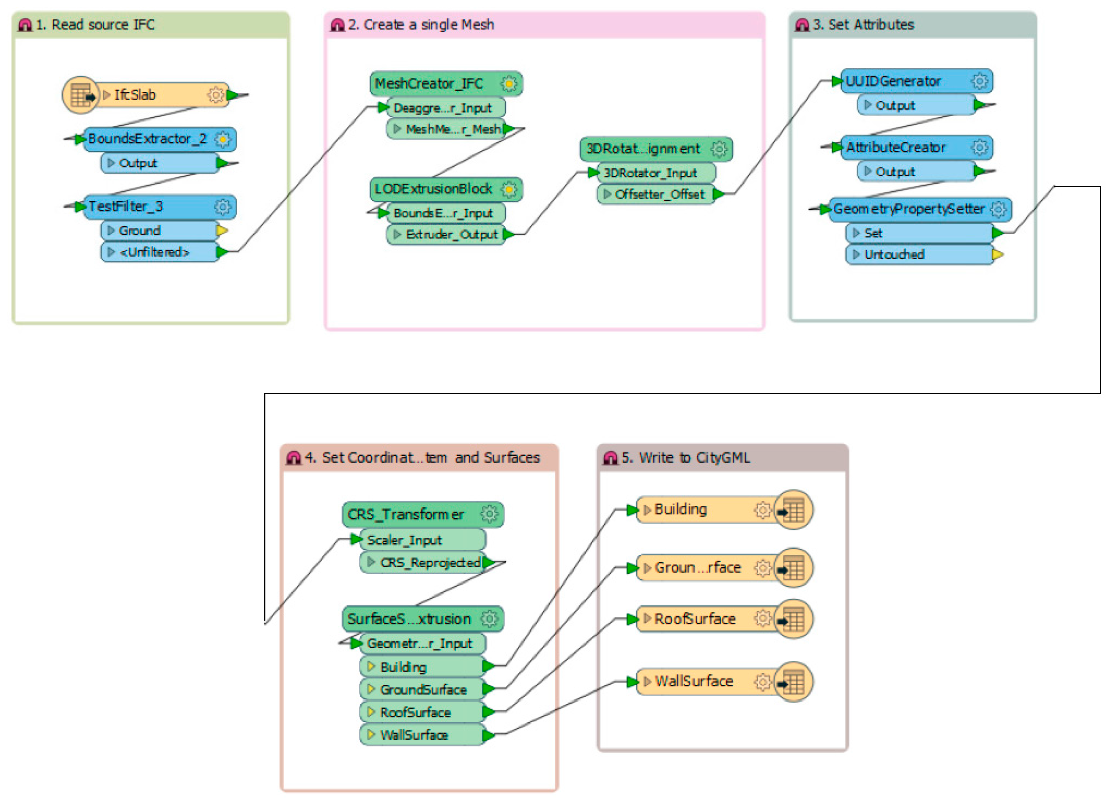
A workflow was designed using FME, as shown in Figure 4. The first step was to read the source. As IFC source, only the IfcSlab was loaded. It was used to create an external envelop of the building in CityGML. By importing the IfcSlab only, it reduced the required processing time to generate the outer envelope of an extrusion block, based on the outermost feature of the building. A BoundExtractor was then used to extract the coordinates of the cuboid bounds of the object, given by _xmin, _xmax, _ymin, _ymax, _zmin and _zmax which covered the six corners. This bound was based on minimum bound to enclose the 3D object in a 3D canvas space. Then, a Testfilter was used to eliminate the unnecessary slab elements from the IFCslab’s feature.
The second step was to create a single mesh. A MeshCreator_IFC custom transformer was created. It automated the process of creating a solid object with surface mesh from the solid read from IFC files. This creates a merged mesh, whereby the model could be enclosed in a single boundary cuboid for further processing in latter stages. Then, a LODExtrusionBlock custom transformer was used to create a solid geometry with a fixed cross-sectional profile based on the IfcSlab, taken from the geometry of the feature generated from the previous transformer. The height of the building has been automatically determined by the entire mesh of the object from the previous transformer. A 3DRotator_Alignment custom transformer was then added. It allowed the user to specify the rotation of the 3D block created and aligns the block to the origin. This would allow for the coordinate to be set accurately in the latter CRS_Transformer.
The third step was to set the attributes of valid geometric traits, for example geometric type, and feature roles. The CityGML writer used these geometric traits to create the correct and valid geometry of the feature according to its schema. The fourth step was to set the coordinate system and surfaces. A CRS_Transformer custom transformer was created. It simplified the process of setting the coordinate system, and reprojected the entire model to the correct coordinates defined. Then, a SurfaceSplitter_3DExtrusion custom transformer was added allowing the different surfaces to be identified before writing to the CityGML. When written in CityGML format, the extruded LOD2 model clearly identified the Ground, Roof and Wall surfaces to form a standardized CityGML model. This workflow could be combined to have several CityGML LOD2 files generated in a single transformation. It could then be loaded to the EDF City Platform and be used to simulate the energy consumption for the individual buildings. EDF City Platform, a City Application and Visualization Interface (CAVI), is a complex system modelling tool developed to help urban planners evaluate the trade-offs in master-planning scenarios, from building to city scale assessments. It evaluates different indicators like energy, emissions, costs, transport, in an integrated way.
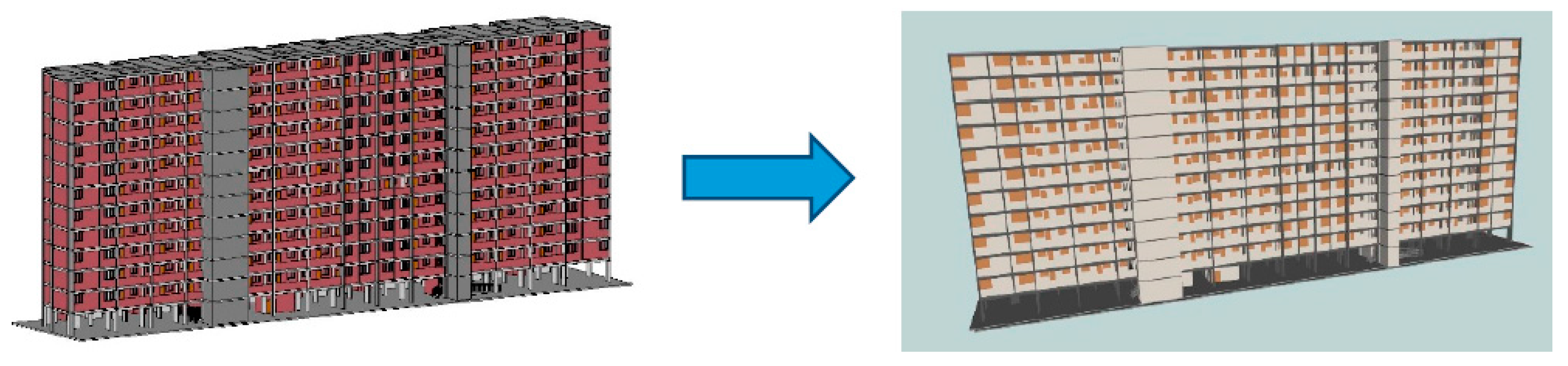
4.2. Main Transformation 2—IFC to CityGML LOD3 (See Figure 5)
Two IFC files have been used to test the CityGML transformation. One IFC was generated from Graphisoft Archicad 20 while another one was generated from Autodesk Revit 2016.
Two excel files have been used in addition to the 2 IFC files in order to provide thermal data for the walls in the CityGML file. The first excel file has been generated from the walls’ schedule from each BIM file.
In Revit, the wall schedule, or any other types of schedule, was generated through the “Schedule/Quantities“ inside the “View” tab and “Create” panel. In the “Schedule/Quantities” window, the category of schedule is chosen, in this case, wall schedule. Then, the needed schedule keys were selected from the element category. The Global Unique Identifier (IfcGUID) and various thermal properties parameters have been selected as key category.
In Archicad, the wall schedule was automatically generated and existing but it can be modified through the scheme setting by adding fields. The GlobalID and several thermal properties fields have been added to the schedule.
The second excel file has been generated from the transformation from the IFC files to a Microsoft Excel format through FME as seen in Figure 6. The wall schedule and the ifc2xls file were then merged in Excel using a VLOOKUP function based on a GlobalID/IfcGUID common key, providing a single xls file containing the wall’s schedule data with the ifc_id identifiers. However, it is also noted that the information must be cleaned up between information generated from Archicad and Revit, for there are slight differences in the attribute naming for the parameters.
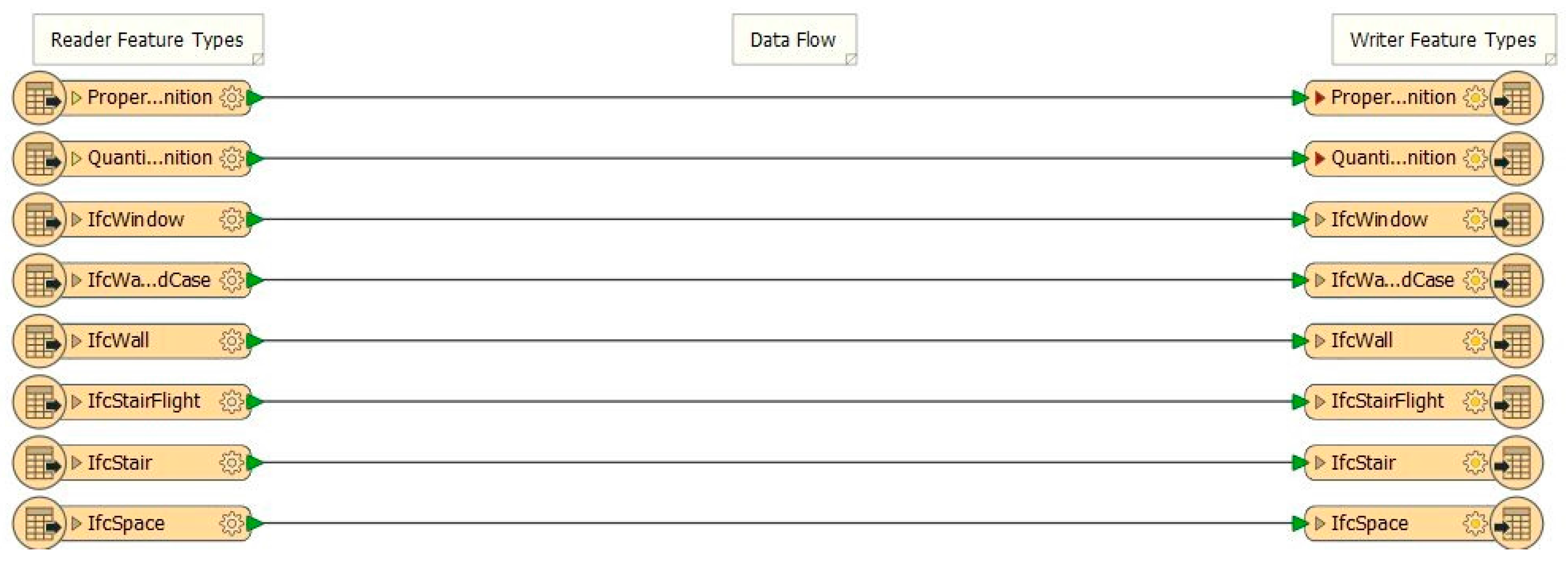
The complete transformation workflow is shown in Figure 7. The transformation process is to encode every feature in the XML schema format according to OGC City Geography Markup Language (CityGML) En-coding Standard (OGC 12-019) [5]. The CityGML schema defines how the different features are grouped together, such as the ID hierarchy structure and the feature roles of each element of the building, based on the level of details of the CityGML model, in this case a LOD3 model.
The workflow transformation described below was adapted from Safe software knowledge center [24]. The first step was to create a simple lod3Solid geometry of the LOD300 IFC model. All Ifc features were loaded except the IfcSpace, QuantitySetDefinition, IfcBuildingStorey and IfcBuildingElementProxy.
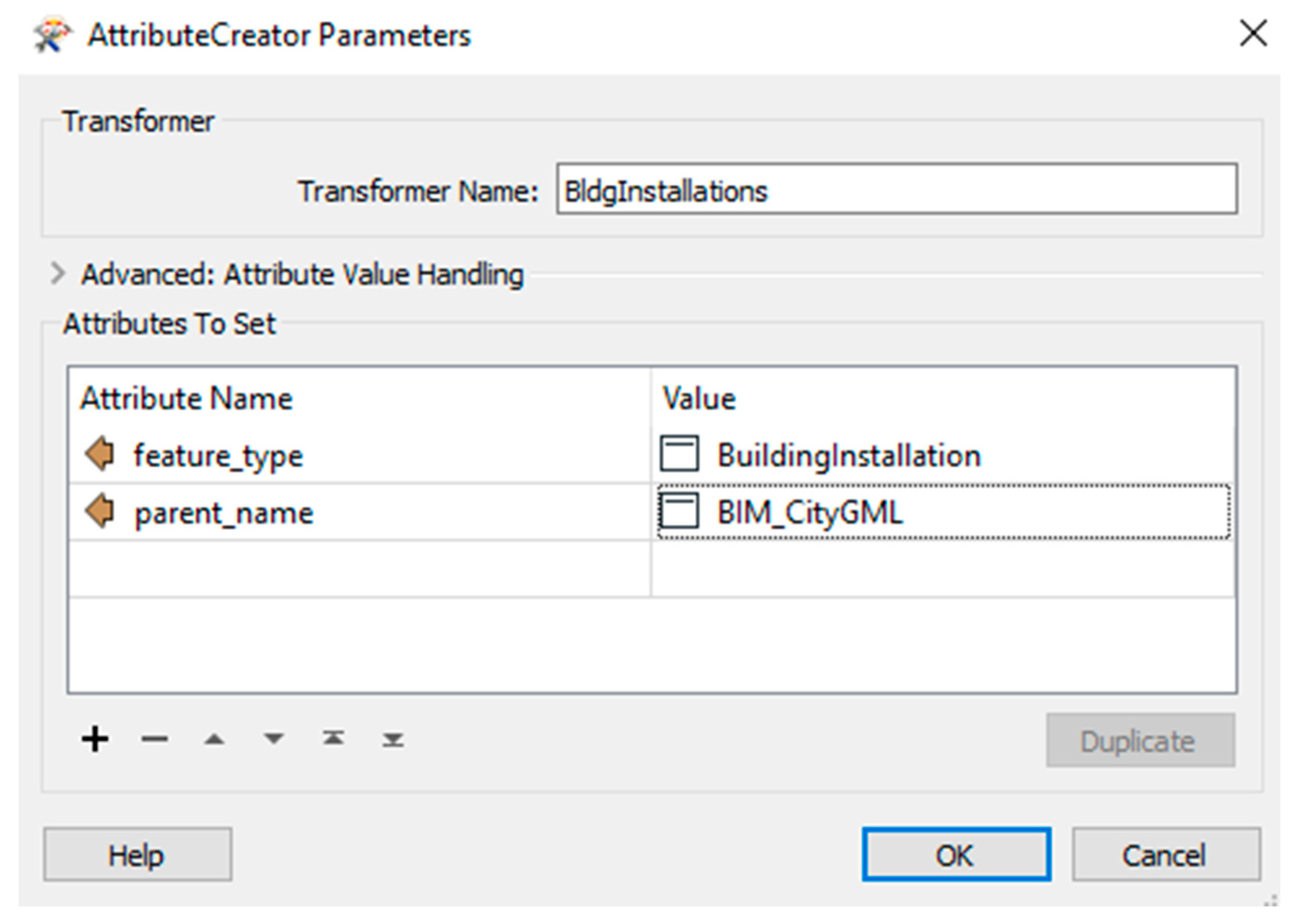
Second was to group CityGML feature types. Before started, a study was done to identify different building elements in the IFC models that had the same or similar representation in the CityGML model. It is common that a CityGML feature type was represented with several building elements in IFC model. If this was the case, both feature types were then merged the same feature types together through an AttributeCreator, as seen in Figure 8. At this stage, each feature obtained new valid gml IDs as the IFC element IDs were no longer valid gml IDs. Each feature also obtained an attribute that could be joined with the gml ID of its parent. The IFC model used coordinate system based on a Google Map address. The correct local reference system, i.e., EPSG:32648, was tagged to each feature by using LocalCoordinateSystemSetter.
Similar to above transformations in previous sections, IFC model was required for mapping to CityGML model, in which all building elements were children of the building feature type in the simplified CityGML model, achieved by multiple joins of cascading gml IDs of parent-child relationship. The building feature type was the result of the IFC LOD300 to CityGML LOD2 transformation.
For building installation, which is considered to be lod3Geometry, it can use an arbitrary GML geometry. Meanwhile, lod3Mulitsurface has been chosen for the building parts. For roofs, walls and floors, by using a CityGMLGeometrySetter, these feature types were restricted to a multisurface geometry, bounded by the building element in CityGML, whereby floor and roof features were found in the IFC Slab building element. To differentiate these features from the wall features in IFC, different attributes were tested, as seen in Figure 9.
For openings, the IFC model has “opening” layer, representing the parent-child relationship of doors and windows to walls. While in CityGML model, doors and windows are represented with the same parent-child relationship, but they are defined as abstract objects, not as actual feature types. The relationship to an abstract object is still maintained by the appropriate setting of citygml_feature_role attribute, which maps them to the correct features.
To preserve the hierarchy, each door and window feature was matched to the ID of the opening, followed by matching to the wall ID, which effectively collapses to the CityGML schema detailing the wall feature encompassing the window and the door.
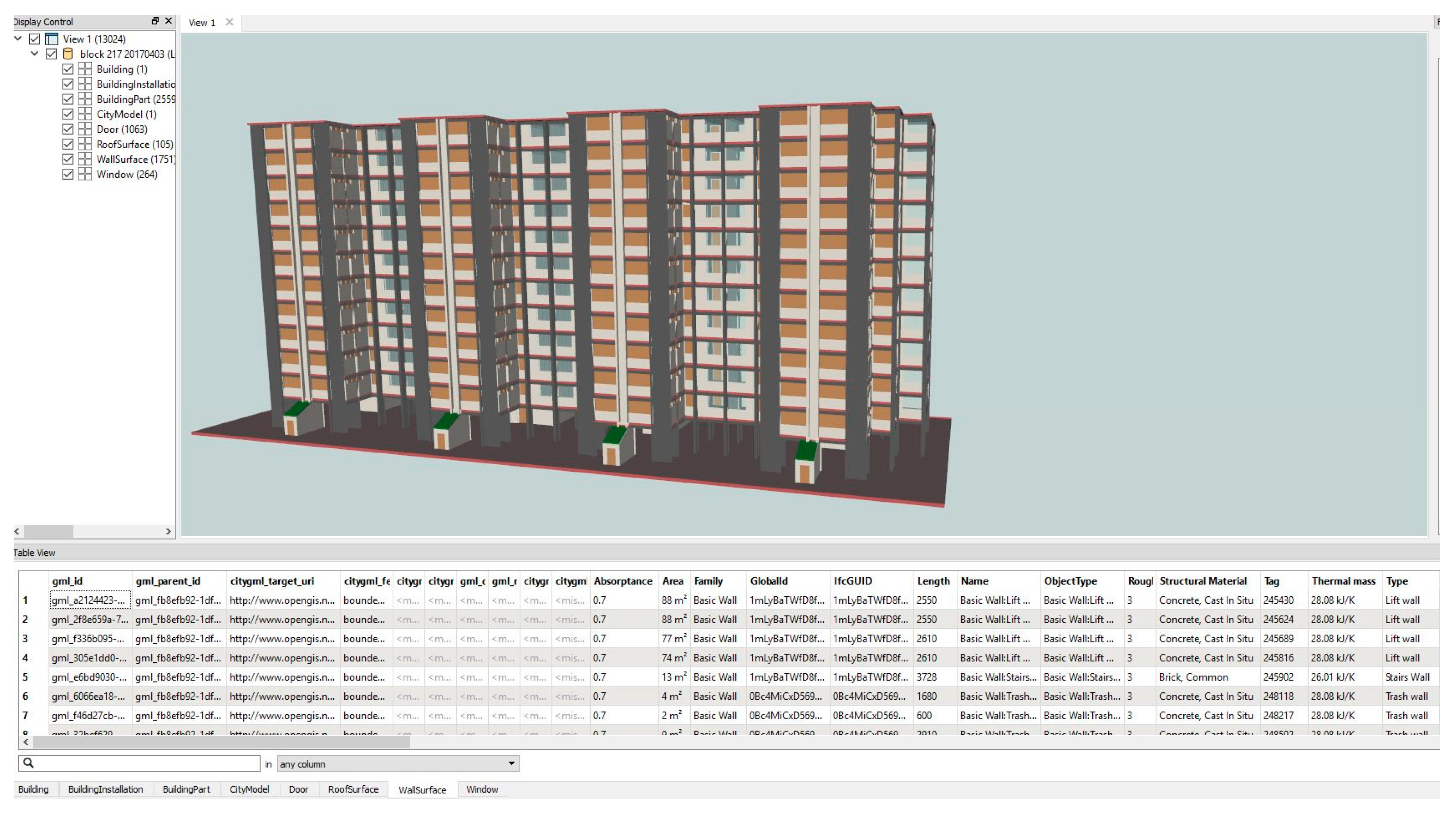
In order to imbue the wall properties with the thermal properties, an additional xls reader was added to provide the dimensions and thermal properties of the wall’s features. The xls reader and the wall appearance feature were merged together based on a common parent attribute ID value. This was a critical step to include additional semantics required in the 3D model defined by the user. The transformation result can be seen in Figure 10.
4.3. Main Transformation 3—IFC to Sketchup (See Figure 11)
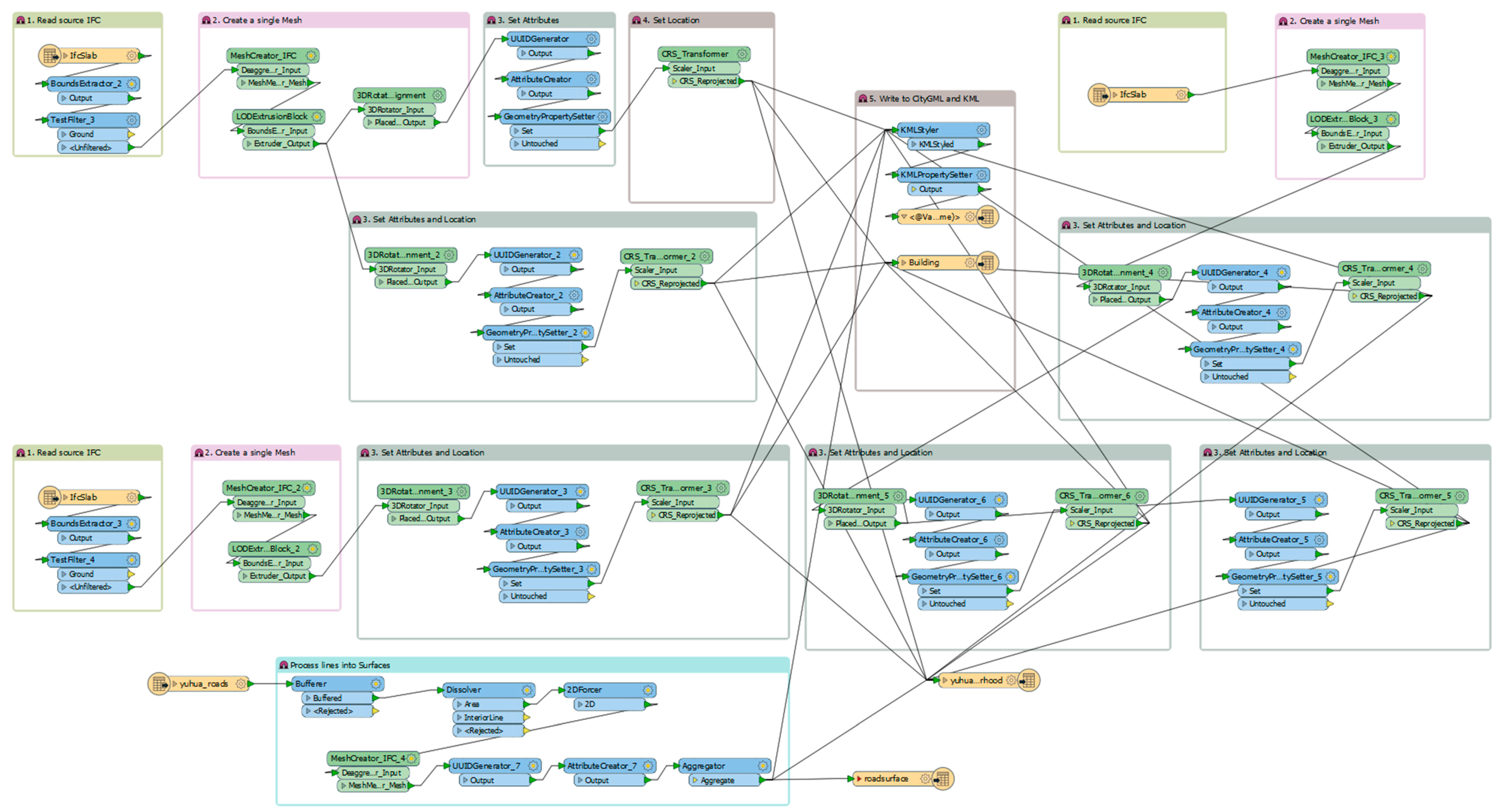
A single IFC building could be easily converted to a Sketchup format using the IfcSlab with a tester to eliminate the unnecessary slab elements (like stairs, roof or ground), then applying a SurfaceFootPrintReplacer and an extruder. The challenge was to combine multiple buildings with road surfaces to form a neighborhood. A workflow has been created to overcome that challenge, see Figure 12.
The workflow is the combination of the extrusion buildings (similar to Figure 4 workflow), together with the roads features. The roads features were based on ESRI Shapefile format, and extracted from OpenStreetMap. They were polylines categorized into major roads, secondary roads, walkways, etc. A conversion of the polylines to surfaces was required to visualize them in CityGML, Sketchup and other formats, as seen in Figure 7.
To create the roads surrounding the buildings of interest, the GIS shapefile was loaded into FME with the polylines. Then, a Bufferer transformer was used to create the boundary around the polylines, which formed the road surfaces. A dissolver was used to combine the different buffers created around the polylines, by eliminating the boundaries. The 2DForcer was then used to replace the buffer area with a surface geometry. The custom MeshCreator_IFC was used to create the surface meshes required to form the surface geometry of the road. Finally, the AttributeCreator was used to define the parameters for CityGML. For roads, we will display as a generic city object, with a LOD2 surface. The neighborhood created from simplifying the IFC and the road surfaces, could be displayed in various applications suitable for further manipulation and web viewing.
5. Discussion
The results presented in this research could help to integrate BIM and CityGML/Sketchup. Throughout the research process, several learning points and challenges were identified.
5.1. File Size
The BIM models have been developed with detailed information on each building component contained within its modeled elements. Despite the model’s complexity, the transformation workflows can handle those models, without any information loss or incorrect geometry. However, as the models are transformed, the file size increased and there were variations of file sizes between BIM models, IFC and CityGML models. The largest increased in file size was observed when generating LOD3 CityGML files as seen in Table 3. Thus, it requires high performance computer to process those complex building models and to render its visualization.
5.2. Embedding of Parameters for CityGML LOD3 Models
5.2.1. BIM Modeling Challenge
It was essential to carefully model both Revit and Archicad models using the same naming for some features to be able to use the same tester in the transformation.
Both Revit and Archicad have for example predetermined standard type of wall already available for selection within their wall tool. Those materials could be duplicated and customized to be identical in both software and specific for the intended use, in this case differentiate internal and external walls.
This common naming has been used to differentiate interior and exterior walls by filtering out internal object by relying on the “external” or “internal” feature name, in order to use the same complex models to generate either LOD2 or LOD3.
5.2.2. Standardization Issues
For the CityGML LOD 3 transformation, a second reader was used to obtain a CityGML feature that contains material data information that could be used for an energy application. Therefore, the conversion could not be standardized and automatized as an external excel file should be added. This excel file was resulting from the export of the wall schedule merged with the ifctoxls FME transformation. Furthermore, Revit and Archicad do not provide the same information in their wall schedules as there is no standard between the two software on this. Indeed, Archicad, in the wall schedule, does only provide the Thermal Transmittance value, but no other thermal properties, while Revit provides values for the Heat Transfer Coefficient (U), Thermal Mass, Thermal Resistance (R) or Absorptance. In consequence, the material data attached to the CityGML feature is not standardized.
5.3. Positioning of 3D Models for CityGML
5.3.1. Geo-Coordinates Positioning for 3D models
BIM/IFC files are traditionally 3D models in a planar surface, and do not contain geographic information. The files are often placed using the Cartesian coordinates system, used often in the computer 3D design tools, whereby the origin of the file is at (0, 0, 0). Geographic Coordinates System (GCS), on the other hand, is used to define the locations on earth, based on a three-dimensional spherical surface. This includes the angular unit of measure, a prime meridian, and the datum based on the spheroid. Although the latitude and longitude used in GCS can locate the point on earth, they are not uniform measure of distances, and only along the equator that the distance represented by one degree of longitude equals that one degree of latitude. Hence, different GCS systems are developed for different regions to account for the distance representation for the longitude and latitude.
To transform the 3D Cartesian model into a 3D GCS based model in CityGML, it is of importance to select carefully the required coordinate systems, as well as the translation process of the coordinates into GCS coordinates. A projected coordinates system is to be selected, in which it converts the locations of the points on a curved surface to locations on a flat plane, which is required in the 3D projection. The selected coordinate system was “EPSG:32648”, with boundaries between 102° E and 108° E, in the northern hemisphere between equator and 84° N, which includes Singapore. This projection allows FME to move the 3D models into the correct location on the map for various tools, which can be verified easily using Google Earth. The generic Mercator system, e.g., WGS84, EPSG:4326, EPSG:3857 was not used as it was not a Cartesian coordinate system, and could not place the objects correctly for the Cartesian SVG space in computer graphics.
5.3.2. 3D Model Rotation and Translation in Space
In 3D graphics, every vertices or points are determined by an (x, y, z) of a plane. The plane of the model can be placed anywhere in space with an offset of w, which the axis is away from the origin (0, 0, 0). Using a 4 × 4 matrix, the transformation of the vertex in space, or 3D object is given by the transformation matrix multiply the vector to give the resultant vertex position [25].
Using FME, the 3DAffiner function helps to transform and translate the object, which is required to place the object in the exact location on the map. An affine transformation preserves the lines or polygon in space, allowing to translate, rotate and scale. The other transformers used in FME is the Scaler, 3DRotator and the Offsetter (translate), which simplifies the process for users.
In FME, if the features are deaggregated, it may cause an error during the translation of the 3D objects. Hence, a mesh merger is often used to group the surfaces together before 3D transformation from the above workflows.
5.3.3. Moving 3D Models to the Correct Location on the Map Using FME
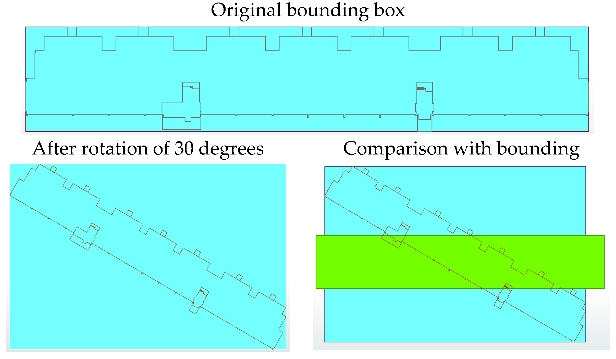
In FME, the IFC files are read with a bounding box determined by the extent of the model. This can be extracted out using the BoundingBoxAccumulator in FME. The 2D bounding box is placed around the footprint of the building, and is always perpendicular to the x and y axis of the drawing canvas.
Referring to Figure 13 below, the extent of the bounding box has changed, due to the rotation of the 3D model. The origin of the bounding box is given at the lower left hand corner of the bounding box, given by the minimum extent of x and y. In addition, the rotation appears to be around the center point of the model, and not about the z-axis, causing a shift in the bounding box. This suggests that the rotation should occur before the translation transformation in FME.
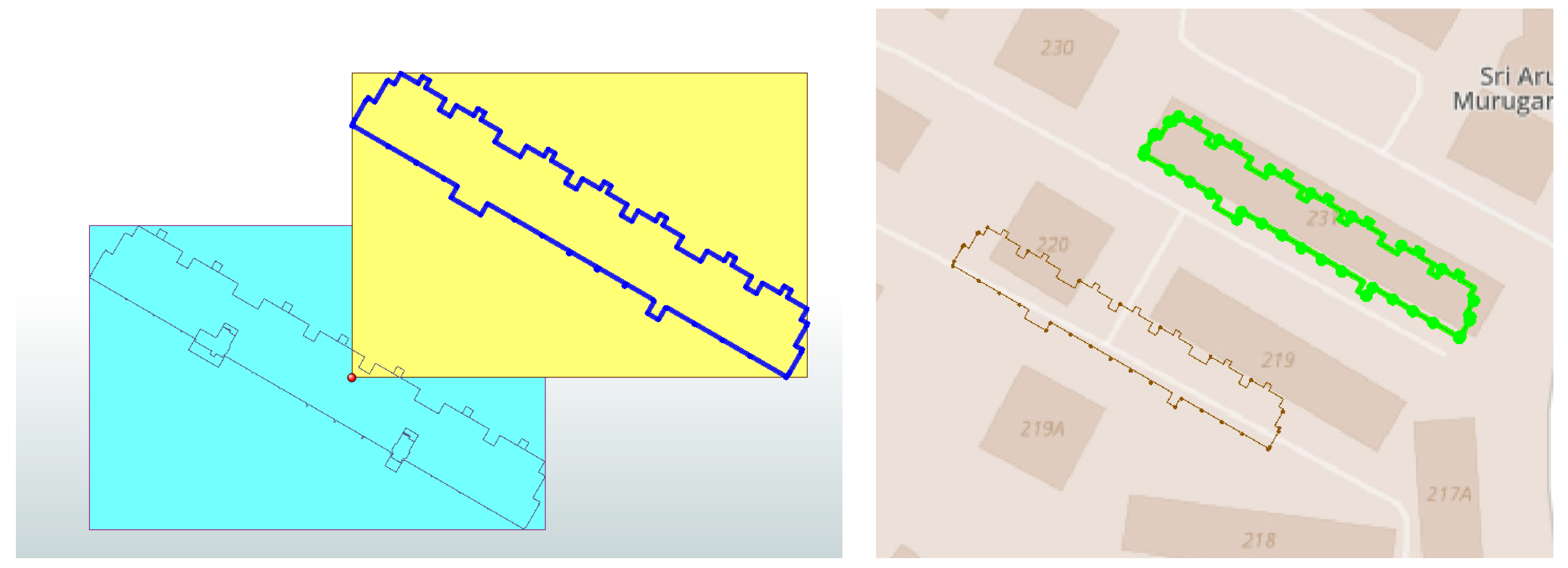
The whole model must be shifted or translated to the origin in the Cartesian coordinate system. Indicated in Figure 14, the model was shifted to the origin (red dot), done after the 3D rotation. If the process is reversed, the model will have bounding boxes not starting from origin. As FME sets the coordinates of the building based on the bounding box origin, it is necessary to perform translation for all models before determining the coordinates and the corresponding coordinate system.
To note, each surface for a deaggregated model is treated as a separate feature, and has its own bounding box and extents. One must be careful about the translation for the model of interest.
6. Conclusions and Future Work
This paper presents a mapping framework between IFC and CityGML/Sketchup. Different level of Details and use cases have also been considered. An Extract, Transform and Load (ETL) software, FME, has been used to generate a transformation schema to achieve a complete and accurate transformation in different LOD.
The research has three objectives. First is a model visualization for web application. To achieve this objective, a simplified model using IFC geometrical information was generated. Second is for the Energy consumption application. Geometry and data information were properly converted, allowing the problem of IFC/CityGML information interoperability to be addressed, as the property information were extracted and transferred to obtain the required information from a use-case perspective. Finally, for the microclimate modeling perspective, a Sketchup file has been generated that could be used by an urban microclimate model, for example STEVE Tool.
Further work could be done to automate the entire conversion and extend the application range, as the study only considered buildings models and road and other kind of special or external features, such as MEP features, site and so on, were not considered.
Acknowledgments
This work is supported by SIT Innovation Grant WBS: R-MNR-E103-A010.
Author Contributions
Steve Kardinal Jusuf is the main Principal Investigator of the project who developed the research topic and methodology; prepared the paper. Benjamin Mousseau is the co-investigator of the project who collaborate with the Principal Investigator developing the research topic. Gaelle Godfroid managed the project, developed the BIM models and together with Jin Hui Vincent Soh worked on the model transformations.
Conflicts of Interest
The authors declare no conflict of interest.
References
- Sewell, P. Semantics of Programming Languages. Available online: https://goo.gl/mTjxjX (accessed on 4 July 2017).
- Cote, P. Activities Bridging the Information Domains of Architecture Engineering Construction and Facilities Management with Geospatial Information Infrastructure. Presented at the National Collegiate FM Technology Conference at the Massachusetts Institute of Technology, Cambridge, MA, USA, 7–10 August 2007; [PowerPoint slides]. Available online: http://web.mit.edu/ncfmtc/pubs/Cote_BridgeInfoDomains.pdf (accessed on 10 August 2016).
- Rouse, M. Definition of Schema. Available online: https://goo.gl/xxtaL9 (accessed on 3 July 2017).
- CityGML Website—What is CityGML? Available online: https://www.citygml.org/about/ (accessed on 25 May 2016).
- El-Mekawy, M.; Östman, A.; Hijazi, I. An Evaluation of IFC-CityGML Unidirectional conversion. Int. J. Adv. Comput. Sci. Appl. 2012, 3, 159–171. [Google Scholar] [CrossRef]
- Gröger, G.; Plümer, L. CityGML—Interoperable semantic 3D city models. ISPRS J. Photogramm. Remote Sens. 2012, 71, 12–33. [Google Scholar]
- Open Geospatial Consortium Inc. OpenGIS City Geography Markup Language (CityGML) Encoding Standard. Available online: https://goo.gl/YqJ8tr (accessed on 3 July 2017).
- El-Mekawy, M. Integrating BIM and GIS for 3D City Modelling—The case of IFC CityGML. Licentiate Thesis, Geoinformatics Division, Department of Urban Planning and Environment, Royal Institute of Technology, Stockholm, Sweden, 2013. [Google Scholar]
- Bahu, J.-M.; Nouvel, R. Development of the CityGML ADE Energy. In Proceedings of the INSPIRE-Geospatial World Forum Conference, Lisbon, Portugal, 25–29 May 2015. [Google Scholar]
- Kolbe, T.H. CityGML—3D Geospatial and Semantic Modelling of Urban Structures. In Proceedings of the GITA/OGC Emerging Technology Summit 4, Washington, DC, USA, 21–23 March 2007. [Google Scholar]
- Van Berlo, L.; de Laat, R. Integration of BIM and GIS: The development of the CityGML GeoBIM extension. In Proceedings of the 5th International 3D GeoInfo Conference, Berlin, Germany, 3–4 November 2010. [Google Scholar]
- Donkers, S. Automatic Generation of CityGML LoD3 Building Models from IFC Models. Master’s Thesis, Department of GIS Technology, TU Delft, Delft, The Netherlands, 2013. [Google Scholar]
- El-Mekawy, M.; Östman, A.; Hijazi, I. A Unified Building Model for 3D Urban GIS. ISPRS Int. J. Geo-Inf. 2012, 1, 120–145. [Google Scholar] [CrossRef]
- Jech, T.J. Lectures in Set Theory; Springer: Berlin, Germany, 1971. [Google Scholar]
- Miguel, M.; Jourdan, J.; Salicki, S. Practical Experiences in the Application of MDA. In Proceedings of the Fifth International Conference on the Unified Modeling Language—The Language and Its Applications, Dresden, Germany, 30 September–4 October 2002. [Google Scholar]
- Noy, N.F.; McGuinness, D.L. Ontology Development 101: A Guide to Creating Your First Ontology. Available online: https://goo.gl/du3Xhr (accessed on 4 July 2017).
- Xun, X.; Lieyun, D.; Hanbin, L.; Ling, M. From building information modeling to city information modeling. J. Inf. Technol. Constr. 2014, 19, 292–307. [Google Scholar]
- Yu, S.-C.; Teo, T.-A. The Generalization of BIM/IFC Model for Multi-Scale 3D GIS/CityGML Models. Available online: http://a-a-r-s.org/acrs/index.php/acrs/acrs-overview/proceedings-1?view=publication&task=show&id=1393 (accessed on 31 May 2016).
- Geiger, A.; Benner, J.; Haefele, K.H. Generalization of 3D IFC Buildings Models. In 3D Geoinformation Science; Benner, J., Haefele, K.H., Eds.; Springer International Publishing: Cham, Switzerland, 2015; pp. 19–35. [Google Scholar]
- Amirebrahimi, S.; Rajabifard, A.; Mendis, P.; Ngo, T. A Data Model for Integrating GIS and BIM for Assessment and 3D Visualization of Flood Damage to Building. Available online: http://ceur-ws.org/Vol-1323/paper27.pdf (accessed on 25 May 2016).
- Karan, E.P.; Irizarry, J.; Haymaker, J. BIM and GIS Integration and Interoperability Based on Semantic Web Technology. J. Comput. Civ. Eng. 2015, 30. [Google Scholar] [CrossRef]
- Kang, T.W.; Hong, C.H. A study on software architecture for effective BIM/GIS-based facility management data integration. Autom. Constr. 2015, 54, 25–38. [Google Scholar] [CrossRef]
- Deng, Y.; Cheng, J.C.P.; Anumba, C. Mapping between BIM and 3D GIS in different level of details using schema mediation and instance comparison. Autom. Constr. 2016, 37, 1–21. [Google Scholar] [CrossRef]
- Safe. BIM to GIS (Advanced)—IFC LOD 200 to LOD 3City GML. Available online: https://goo.gl/nkihFH (accessed on 17 July 2017).
- Opengl-Tutorial. Tutorial 3: Matrices. Available online: https://goo.gl/W1kPEk (accessed on 17 July 2017).
Figure 1.
Methodology diagram.
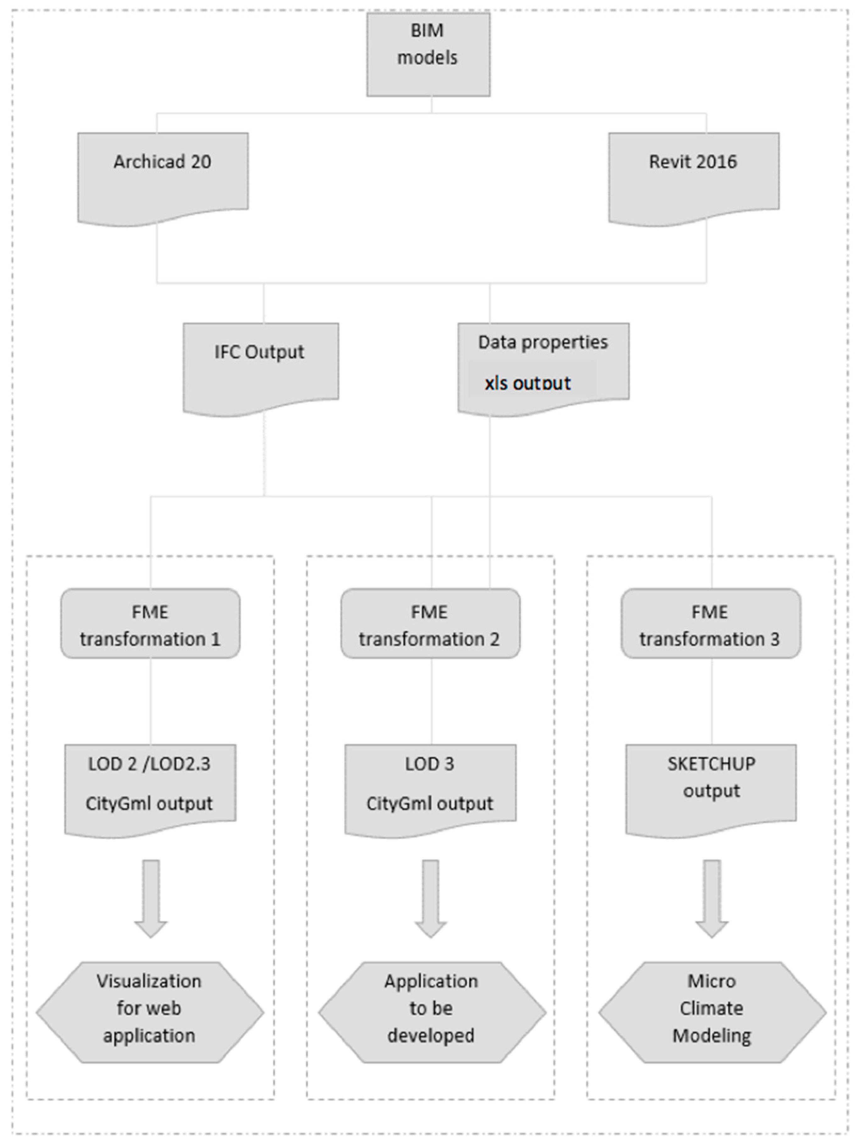
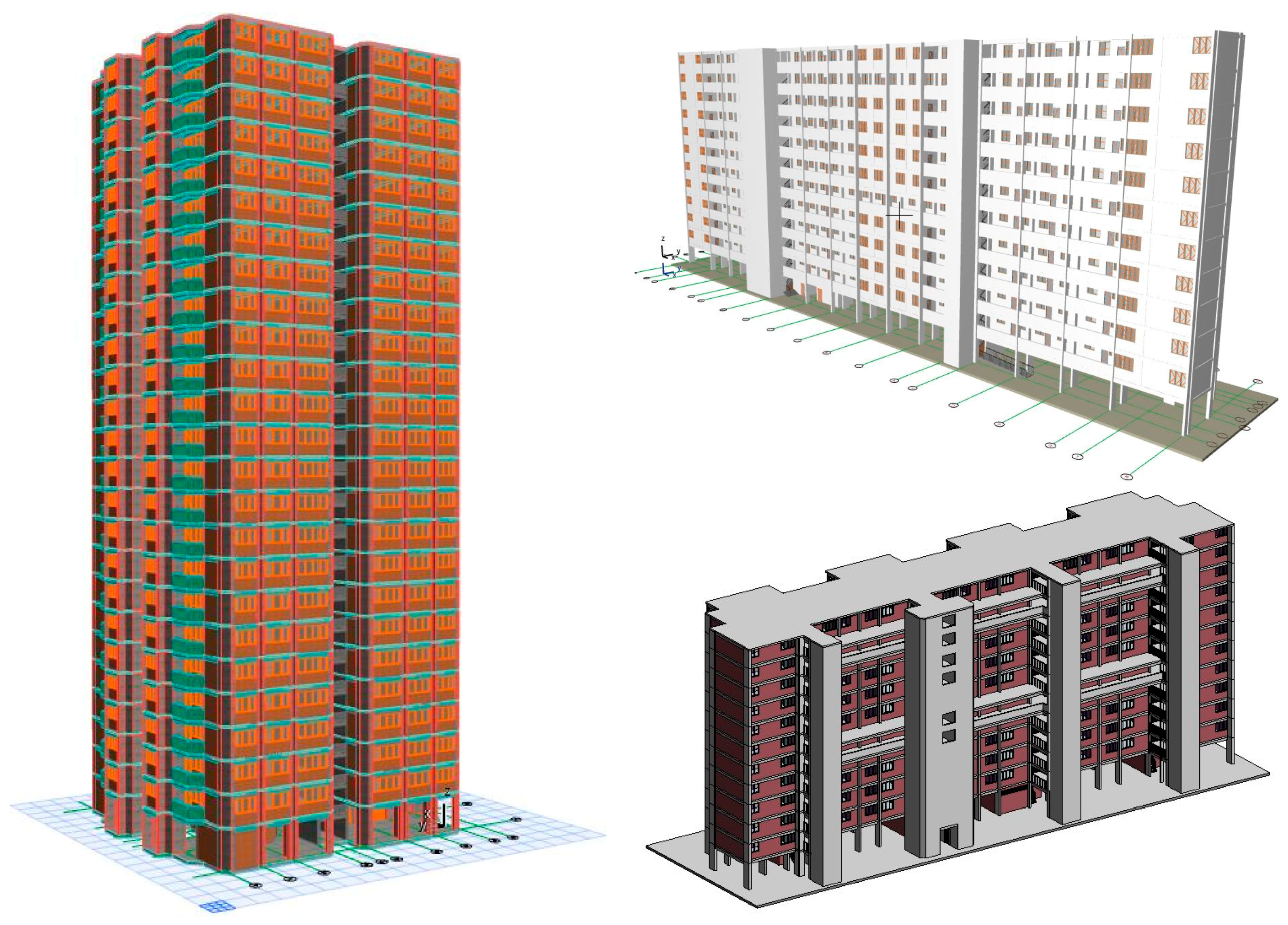
Figure 2.
“Point” block apartment Archicad Model (left), “Slab” block apartment Archicad model (upper right) and “Slab” block apartment Revit Model (lower right).
Figure 2.
“Point” block apartment Archicad Model (left), “Slab” block apartment Archicad model (upper right) and “Slab” block apartment Revit Model (lower right).

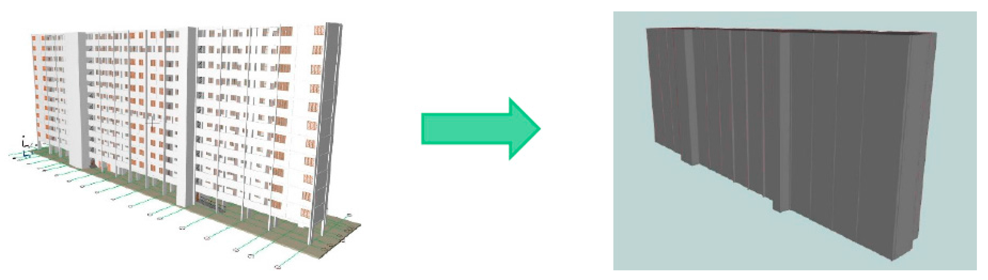
Figure 3.
IFC Archicad model (left) transformed into CityGML LOD2 model (right).

Figure 4.
IFC to CityGML LOD 2 transformation workflow.

Figure 5.
Example of IFC model (left) to CityGML LOD2.3 model (right).

Figure 6.
IFC to Xls workflow (example).

Figure 7.
IFC to CityGML LOD3 workflow transformation.
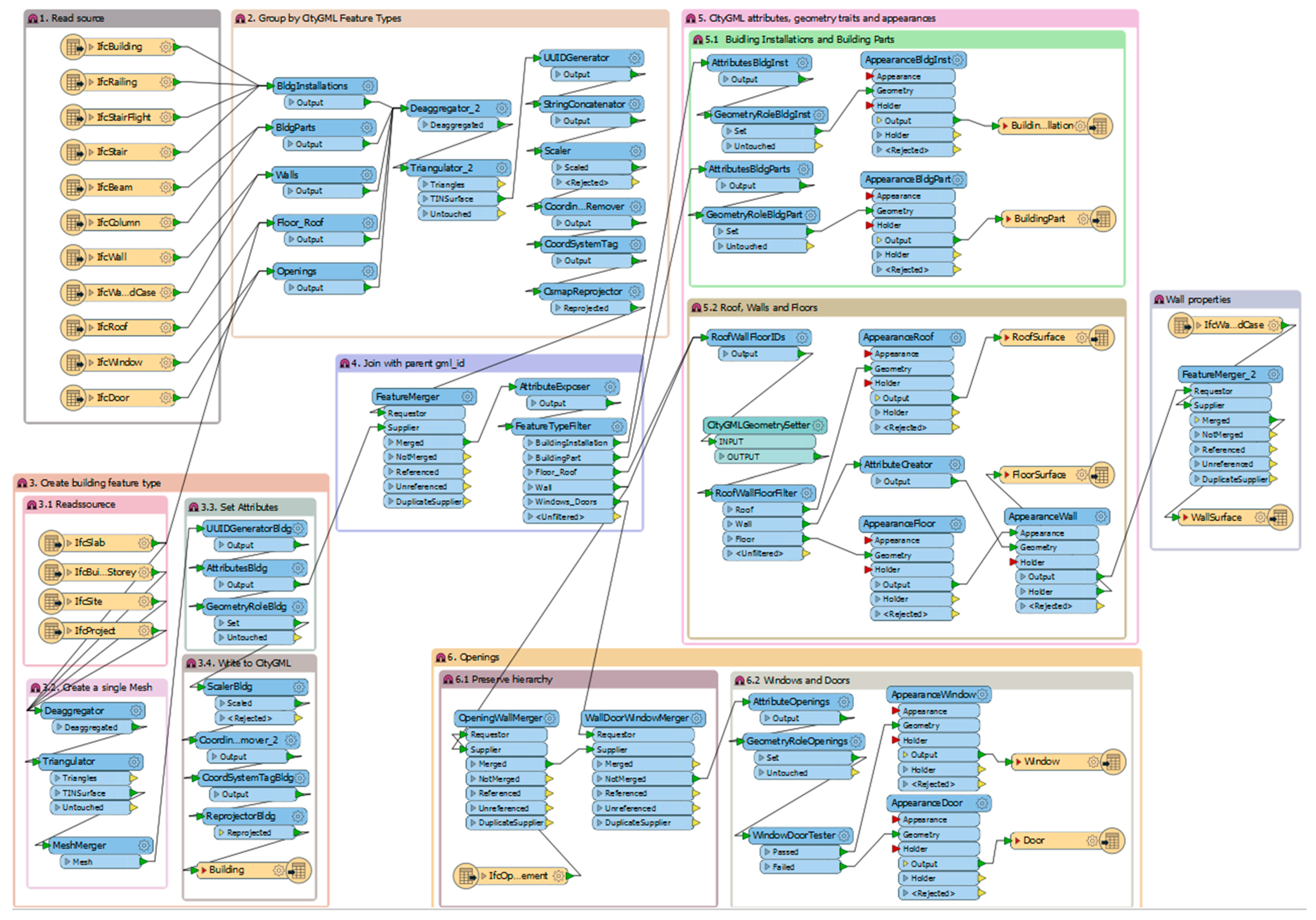
Figure 8.
AttributeCreator Parameter LOD3 BuildingInstallation.

Figure 9.
TestFilter Parameters for CityGML attributes.
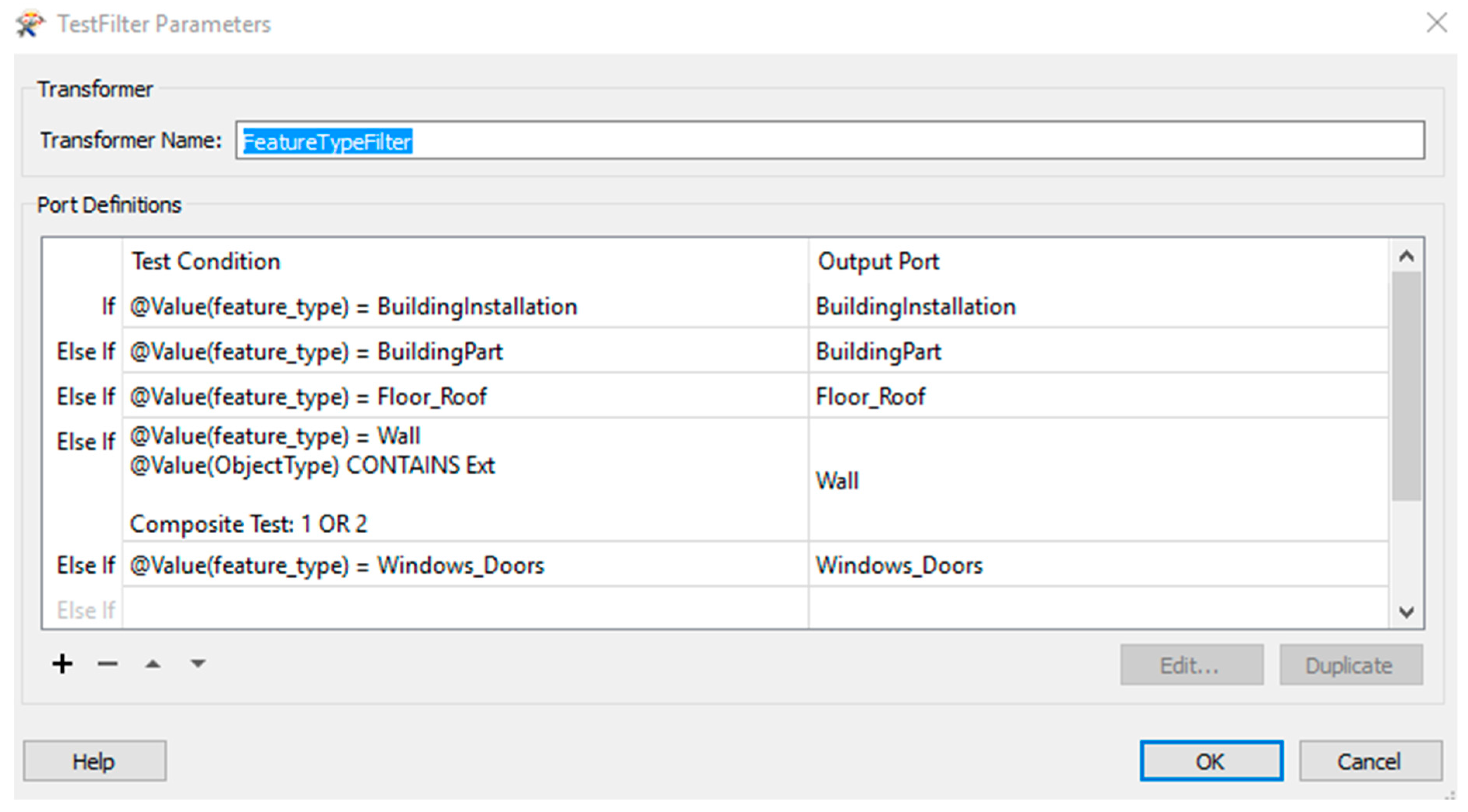
Figure 10.
LOD3 CityGML model.

Figure 11.
IFC Autodesk Revit model (left); Sketchup model (right).
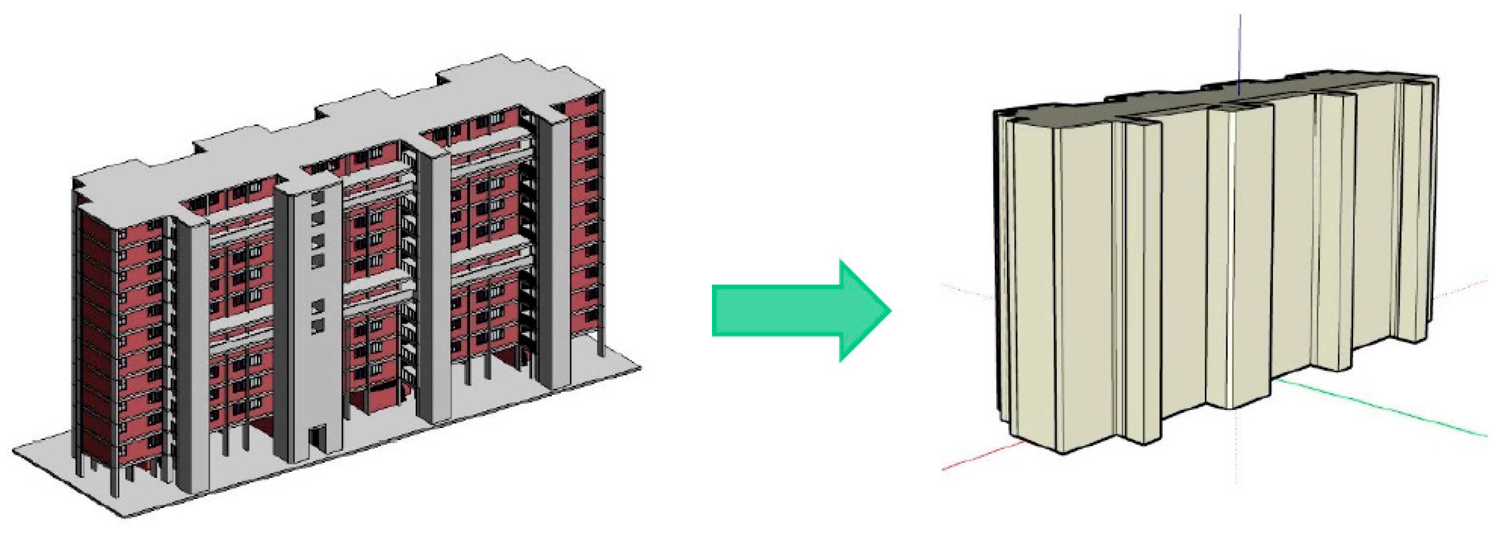
Figure 12.
Workflow of multiple buildings from IFC and Shapefile to CityGML and KML.

Figure 13.
Bounding box of IFC model before and after 3D rotation.

Figure 14.
Bounding box of block 231 after translation.

Table 1.
LOD 0–4 of CityGML with its accuracy requirements [7].
Table 1.
LOD 0–4 of CityGML with its accuracy requirements [7].
| LOD0 | LOD1 | LOD2 | LOD3 | LOD4 | |
|---|---|---|---|---|---|
| Model scale description | regional, landscape | city, region | city districts, projects | architecturel models (outside), landmark | architectural models (interior) |
| Class of accuracy | lowest | low | middle | high | very high |
| Absolute 3D point accuracy (position/height) | lower than LOD1 | 5/5 m | 2/2 m | 0.5/0.5 m | 0.2/0.2 m |
| Generalisation | maximal generalisation (classification of land use) | object blocks as generalized features; >6 × 6 m/3 m | object blocks as generalized features; >4 × 4 m/2 m | object blocks as real features; >2 × 2 m/1 m | constructive elements and openings are represented |
| Building installations | - | - | - | representative exterior effects | real object form |
| Roof form/structure | no | flat | roof type and orientation | real object form | real object form |
| Roof overhanging parts | - | - | n.a. | n.a. | Yes |
| CityFurniture | - | important objects | prototypes | real object form | real object form |
| SolitaryVegetaionObject | - | important objects | prototypes, higher 6 m | prototypes, higher 2 m | prototypes, real object form |
| PlantCover | - | >50 × 50 m | >5 × 5 m | <LOD2 | <LOD2 |
| …to be continued for the other feature |
Table 2.
Summary of literature review.
| No | Author | CityGML and IFC Integration/Conversion method | Deliverable |
|---|---|---|---|
| 1 | Bahu and Nouvel (2015) [9] | Application Domain Extension (ADE) | Focus on Energy domain, i.e., Energy ADE |
| 2 | Kolbe (2007) [10] | Use CityGML model as source for the generation of 3D visualization through potralaying method | Potralaying method on CityGML model |
| 3 | Van Berlo and de Laat (2011) [11] | Unidirectional transformation from IFC to CityGML | CityGML extension for IFC, called GeoBIM extension |
| 4 | El-Mekawy, et al (2012) [13] | Unidirectional transformation from IFC to CityGML | Schema matching of IFC and CityGML model schema, with three matching levels: “full (direct)” match, “partial” match and “no” match |
| 5 | Donkers (2013) [12] | Extraction and mapping of IFC semantics to CityGML semantics, followed by geometric generalization using Boolean and morphological operations | Automatic generation of IFC model from CityGML LOD3 model |
| 6 | El-Mekawy, et al (2012) [13] | Unified Building Model (UBM) through reference ontology, removing relationships between model classes then rebuilt them with Unified Modeling Language (UML) | Unified Building Model (UBM) method |
| 7 | Xun, et al (2014) [17] | City Information Modeling (CIM), comparing and mapping the data schema of IFC and CityGML models | City Information Modeling (CIM) method |
| 8 | Yu and Teo (2014) [18] | Conversion of CityGML model from IFC model through geometric division and geometric information editing | Mthod of geometric divison through node points’ coordinates calculation, editing geometric infomration and attribute conversion |
| 9 | Geiger, et al (2015) [19] | Semantical and geometrical generalization of IFC models | ExtrusionBaseModel |
| 10 | Amirebrahmi, et al (2015) [20] | Conceptual data model using UML class diagaram | UML class diagram on a study analyzing building damages due to flooding |
| 11 | Karan, et al (2015) [21] | Ontology construction, semantic integration through interoperable data formats and standards, and query of heterogeneous information sources. | Semantic web technology method |
| 12 | Karan and Hong (2015) [22] | BIM/GIS-based information Extract, Transform and Load (BG-ETL) architecture | BG-ETL architecture |
| 13 | Deng, et al (2016) [23] | Mapping rules between IFC and CityGML using an instance-based method and designed a reference ontology and CityGML ADE for schema mediation | Mapping rules using instance-based method and reference ontology |
Table 3.
Comparison between file type and file size.
| Models | Revit 2016 File Size | Archicad 20 File Size | IFC File Size | CityGml LOD2 File Size | CityGml LOD3 File Size | Sktechup File Size |
|---|---|---|---|---|---|---|
| Revit_25 storey | NA | 42,961 KB | 31,213 KB | 26,184 KB | 1,587,878 KB | N/A |
| Archicad_13 storey | 45,812 KB | NA | 32,430 KB | 33,590 KB | 305,148 KB | N/A |
| Revit/Archicad_13 storeys | 41,176 KB | 33,660 KB | 28,851 KB (Archicad) 44,117 KB (Revit) | 27,412 KB | 396,457 KB | N/A |
© 2017 by the authors. Licensee MDPI, Basel, Switzerland. This article is an open access article distributed under the terms and conditions of the Creative Commons Attribution (CC BY) license (http://creativecommons.org/licenses/by/4.0/).
Share and Cite
MDPI and ACS Style
Jusuf, S.K.; Mousseau, B.; Godfroid, G.; Soh, J.H.V. Path to an Integrated Modelling between IFC and CityGML for Neighborhood Scale Modelling. Urban Sci. 2017, 1, 25. https://doi.org/10.3390/urbansci1030025
AMA Style
Jusuf SK, Mousseau B, Godfroid G, Soh JHV. Path to an Integrated Modelling between IFC and CityGML for Neighborhood Scale Modelling. Urban Science. 2017; 1(3):25. https://doi.org/10.3390/urbansci1030025
Chicago/Turabian StyleJusuf, Steve Kardinal, Benjamin Mousseau, Gaelle Godfroid, and Jin Hui Vincent Soh. 2017. "Path to an Integrated Modelling between IFC and CityGML for Neighborhood Scale Modelling" Urban Science 1, no. 3: 25. https://doi.org/10.3390/urbansci1030025