
Design of a Pressurized Smokeproof Enclosure: CFD Analysis and Experimental Tests


1
Department of Structural and Geotechnical Engineering, University of Rome “La Sapienza”, Roma I-00100, Italy
2
Italian National Fire Rescue and Service, Roma I-00100, Italy
*
Author to whom correspondence should be addressed.
Safety 2017, 3(2), 13; https://doi.org/10.3390/safety3020013
Submission received: 6 October 2016
/
Revised: 10 March 2017
/
Accepted: 21 March 2017
/
Published: 23 March 2017
(This article belongs to the Special Issue Fire Safety)
Abstract
:Pressure differential systems have the purpose of maintaining tenable conditions in protected spaces for different types of building safe places, like escape routes, firefighting access routes, lobbies, stairwells and refuge areas. The aim of pressure differential systems is to establish airflow paths from protected spaces at high pressure to spaces at lower or ambient pressure, preventing the spread of toxic gas released during a fire. This strategy ought to be supported by a detailed design of the necessary air supply, considering also the cycle of opening and closing doors during the egress phase. The paper deals with the design of a simple pressure differential system intended to be used in a building as a pressurized smokeproof enclosure. Specifically, experimental tests and numerical modelling are conducted with the objective of characterizing the pressure evolution in a small compartment under different conditions and through a cycle of door opening. Experimental tests are conducted in a simple 3-m side cubic enclosure with two doors and no vent openings. While a centrifugal fan blows constant airflow inside the structure, the pressure trend in time is recorded during steady state and transient conditions; additionally, the velocity of the airflow across the doors has been measured by means of an anemometer. Numerical CFD (computational fluid dynamics) simulations are carried out to reproduce the same smokeproof enclosure configuration (both geometrical and boundary conditions) using the fire dynamics simulator (FDS). Furthermore, specific attention is paid to the modelling of the leakage across the doors, directly inserted in the model through a localized HVAC (heating and venting air conditioning) advanced leakage function. Comparisons between experimental tests and numerical simulations are provided. Once the model was correctly calibrated, other geometrical and mechanical configurations have been studied, looking for convenient and efficient positions of the fan in order to fulfill the requirements of the pressure differential, airflow velocity and door handle force. The paper highlights some fundamental aspects on the pressurization and depressurization during steady state and transient phases, trying to identify if there are airflow profiles typical of some geometrical configurations.
1. Introduction
Life safety is the primary goal for fire engineers, and both active and passive fire protection measures can be adopted to pursue the correct design of the fire safety of buildings. According to fire statistics [1], the main threat in the case of fire is human exposure to smoke and toxic gases; therefore, the fire safety design ought to address also smoke management strategies. Smoke effects can be responsible for fatalities and injuries, and both lethal and incapacitation thresholds have been studied by Purser since 1986 [2,3,4]. Smoke management systems are crucial for preventing (or at least limiting) those consequences and in some cases, if required by the importance of the building, must be able to reduce property loss due to smoke and hot gas damages. According to the state of the art in designing smoke control and management systems [5,6], smoke management strategies in case of fire can be implemented using one or more of the following techniques: compartmentation, dilution, air fluxes, buoyancy and pressurization.
This paper deals with the design and characterization of a pressurized smokeproof enclosure. The purpose of a smokeproof enclosure is to prevent the spread of smoke from the compartment of first ignition to other areas likely to be crossed by occupants during the egress phase by disconnecting these two parts of the building through a small enclosure in overpressure.
Generally, these enclosures are fire compartments provided with two or more doors where only one door is released at a time in order to prevent continuous passage and leakage (see Figure 1). These systems are mostly used, for instance, to protect the main vertical means of egress like stairs and fire elevators, or refuge areas, where occupants can wait for help if unable to leave the building independently (hospitals, nursing home, etc.). This kind of system might represent a good alternative to the pressurization of large volumes, such as stairwells, because, due to their limited extension, they do not require the use of such powerful (and expensive) fans.
However, the operating principle of smokeproof enclosures is not easily coupled with occupants’ evacuation. In fact, considering the egress from a fire floor ending with a smokeproof enclosure, the action of opening the entrance door is responsible for an airflow exiting the door that should contrast the entrance of smoke. Meanwhile, the pressure differential inevitably decreases due to the direct contact of the internal and external volumes. Then, the door closes and the mechanical ventilation must be able to restore the initial overpressure conditions quickly before the door will be opened again. If the level of overpressure does not increase in a short time, in case of fire, the smoke might enter the compartment through the first entrance door and exit through the second exit door, reaching exactly the opposite purpose of preventing the entrance of smoke. These uncertainties in the effectiveness of smokeproof enclosures are in agreement with Lay’s work [7] that doubted the correctness of the operating conditions of pressurization systems.
Considering the restoration of the initial overpressure conditions, the velocity of the process depends mainly on the ratio between the volume of the compartment and the dimensions of the door. The smaller is the ratio, the quicker are the transient phases of decreasing and increasing of the overpressure, respectively at the opening and closing of the door. For a larger value of the ratio of the pressurized volume/door area, the dynamics of the system change. In the case of pressurized stairwells for example, depending on the flow of people (usually measured in people/seconds), a minimum pressure differential is likely to be still guaranteed even at the opening of one door. However, restoring the initial pressure differential might be much more difficult and expensive since the volume is much larger than the dimension of the door.
The key of the whole phenomenon is in the power of the fan and its effective airflow. Generally, there are different levels of airflow and velocity available for this use. Automatic control systems are a good solution to adjust the inlet of air (and thus the velocity of the fan) depending on the operating conditions, as is reported in the work of Youa et al. [8]. When useful, overpressure relief is a way to provide high velocities across open doors and a sustainable level of door handle forces when doors are closed.
Apart from life safety of occupants, pressurization is a useful strategy to facilitate the extinguishing and rescue operations of firefighters. The prevision of a space protected from toxic gases improves the working conditions of firefighters: if well designed, pressurized stairwells (and sometimes adjacent lobbies) represent a safe space to enter the building and directly attack the fire floor. In this case, more powerful fans are required to maintain tenable conditions for firefighters, because fire conditions inside the building could be well developed, but not as high as external windows breakage would require. Well-established literature is available for these systems [9,10,11,12].
In the following section, an overview of the current regulations is presented, with some definitions and requirements for key parameters in the pressurization field. The presented work is substantially planned and carried out according to the EN 12101-6, but for completeness, NFPA 92 (National Fire Protection Association) is also outlined. Some regulations are certainly more specific than other ones, but all of them agree on some general aspects:
- −
- Minimum differential pressure is needed to contrast the entrance of smoke, considering that buoyancy and heat transfer effects cause local overpressure (most of the times in the order of 8–10 Pa [10]);
- −
- Maximum differential pressure is linked to the possibility of easily opening the door by people;
- −
- Minimum velocity of airflow across the doors is important for the egress phase; the value must be able to prevent the massive entrance of smoke through open doors;
- −
- Maximum velocity of airflow across the open doors should not exceed upper thresholds because of possible turbulence effects at the interface.
Maximum door handle force must be limited especially for elderly, impaired people and children.
2. Regulations
2.1. Italian Regulations
According to the Italian Technical Regulations for Fire Prevention, recently approved by the Ministerial Decree on 3 August 2015 [13], a smokeproof enclosure is a fire compartment with no (or negligible) probability of fire ignition, due to almost total absence of fire load. The boundary structures of the system must be at least 30 min fire resistant, with automatic door closer systems and doors guaranteeing cold smoke resistance. Generally, smokeproof enclosures are quite small rooms, placed to protect means of egress, i.e., before the entrance of the stairwell and the elevator enclosure or a specific compartment where fire risk is high.
In order to perform adequately, apart from the previous characteristics, one of the following design solution must be chosen by designers to build-up a so-called smokeproof enclosure:
- −
- Direct vent openings (such as vertical or roof windows), always kept opened (total area not less than 1 m2);
- −
- Air chimney ending outside, over the roof (section area not less than 0.1 m2);
- −
- Mechanical ventilation through fans keeping the internal environment in overpressure at least at 30 Pa in emergency conditions (pressurized smokeproof enclosure).
The first two solutions intend to maintain the stratification of smoke that could accidentally enter the enclosure, ensuring fresh air, free of smoke, in the lower zone where people walk and naturally extracting hot toxic gases thanks to the buoyancy effect. Otherwise, the last solution (the only one analyzed in the paper) works preventing the entrance of smoke inside the room through the difference of pressure between the internal pressurized volume and the adjacent compartment.
The choice of the proper solution is left to the practitioners, but most of the times, pressurization is the easiest way, due mostly to geometrical constraints, like the necessity of the protection of interior vertical means of egress. No other requirements are asked except from the minimum level of internal pressure and the fact that people should be able to open the doors easily. For the design of pressurized systems, the Italian Technical Regulations refer practitioners to the use of the European standard EN 12101-6.
2.2. European Regulations
The EN 12101 is the series of European Standards for smoke and heat control systems, and Part 6 contains technical specifications for the design of pressure differential systems [14]. This strategy of fire protection is implemented in categories of systems, with different requirements and design conditions.
Pressurization starts when smoke is detected or a fire alarm is transmitted. Regarding positive pressurization, in addition to the minimum level of pressure within protected spaces, other requirements are specified, such as velocities of the airflow exiting the pressurized space when doors are opened and forces acting on the door handle when doors are closed. Specifications about the position of the air supply points, the presence of natural vents or shafts and the necessity of overpressure relief (compensated systems) are also addressed.
The EN 12101-6 standard refers to different possible configurations of spaces to be pressurized, depending on the desired safety performance level and the geometrical constraints of the building; the practitioner will choose the most convenient solution, considering all of the requirements to fulfill. For non-standard situations, a fire engineered solution is recommended, especially where multiple flow paths are present.
In Table 1, there is a list of the main requirements that a building must satisfy depending on the given system class. The airflow criterion refers to the situation when at least an internal door is opened at a certain story and the external door can be opened or not. When both internal and external doors are closed, the pressure criterion must be satisfied, verifying also the door handle force (generally, an overpressure of 60 Pa must not be exceed).
The idea behind these criteria is that after smoke detection, pressurization starts, and the protected space is kept at a given level of overpressure taking into account the leakage across walls, doors and other boundaries letting air flow by cascade towards the accommodation and from there up to the outside of the building through air release paths. During the egress phase, the airflow exiting the protected space must be able to contrast the entrance of smoke driven by buoyancy forces.
Among all of the classes, it should be noticed that even if the required values at the smoke barriers can be the same (i.e., Class C and Class E), the number of open doors that must be considered during the design phase is different, because the evacuation process is different and so the use of the protected space (see Figure 2). In fact, for Class C, the stairwell is considered to be occupied for the nominal period of evacuation. In this case, some smoke leakage inside the stairwell is tolerated, because the airflow of the pressurization system will clear the stairway from this smoke. When all doors are closed, the pressure should be 50 Pa, whereas when the final external exit is opened, a minimum value of 10 Pa is required. For Class E, instead, people could be inside the building for a greater time after smoke detection due to the phased evacuation strategy: a minimum value of 10 Pa must be guaranteed when the final external door and two internal doors of no more than two adjacent floors (not including the fire floor) are opened. Depending on the number of open doors required for the airflow criterion, the minimum needed air supply changes and, so, the size of the fans.
Acceptance testing:
Generally, the following parameters should be tested:
- −
- Pressure differential;
- −
- Net pressure differential;
- −
- Air velocity;
- −
- Door opening force;
- −
- Activation of system.
The measurements of air velocity through the relevant doors must be taken while all other doors are opened or closed in accordance with the appropriate class of system. At least eight measurements, uniformly distributed over the doorway, need to be taken to establish an accurate air velocity. There are no explicit specifications about the positions of the measurement points, which are left to the designer. However, the mean of these measurements must be calculated. The calibration of all test equipment should guarantee an accuracy of 5%.
2.3. American Regulations
The NFPA 92 [15] is the Standard for Smoke Control Systems, covering both containment and management systems, including stairwell pressurization systems and testing requirements (it replaces NFPA 92A and NFPA 92B).
The general definition of pressurized stairwells is a type of containment smoke control system in which stair shafts are mechanically pressurized, with respect to the fire area, with the outdoor air preventing contamination by smoke. The pressure differences across doors shall permit people to open them easily as defined in NFPA 101 [16], but at the same time, should provide for smoke containment. Other design approaches could be pressurization of elevators, vestibules, refuge areas or zoned smoke control.
Unlike the EN 12101-6, the NFPA 92 contains no specifications about airflow velocity requirements when doors are opened, but an average value of 1 m/s should not be exceeded for not ending with turbulence mixing effects. In Table 2, the dependence of minimum design pressure difference on the ceiling height and the presence of sprinklers is shown (with the sprinkler system, the fire is expected to be controlled below a low level of the rate of heat release, and as a consequence, lower pressure differences are sufficient to prevent the entrance of smoke).
Short-term deviations from the suggested minimum design pressure difference might not have a serious effect on the protection provided by a smoke control system. There is no clear-cut allowable value for this deviation (it depends on many parameters): intermittent deviations up to 50 percent of the suggested design value are considered tolerable in most cases.
Acceptance testing:
According to the NFPA 92, the following parameters should be tested:
- −
- Total volumetric flow rate;
- −
- Airflow velocities and direction;
- −
- Door opening forces;
- −
- Pressure differences;
- −
- Ambient indoor and outdoor temperatures;
- −
- Wind speed and direction.
It is explicitly specified that tests using smoke are not useful to evaluate the quality of pressure smoke control systems. In fact, normally, smoke bombs provide only cold smoke and are not able to simulate the real dangerous conditions typical of a fire (buoyancy forces and stratification would be also questionable).
3. Basic Analytical Design of a Pressurized Smokeproof Enclosure
One of the first tasks in the design stage of a pressurization system involves considerations of the necessary air supply to maintain a specific performance requirement. In the case of a system that injects an air flux inside one enclosure that separates two or more other spaces, a first requirement is to maintain a minimum overpressure inside the enclosure; a second requirement is to obtain a minimum velocity of the air exiting from the enclosure when the door confining the fire floor is opened.
Usually the boundaries of the system may consist of walls, doors and windows: gaps around doors, unintentional cracks in walls and direct openings represent leakage paths. The desired pressure is maintained by a properly-designed and controlled ventilation system to achieve a specific airflow compensation as determined through the leakage area.
The pressure criterion states that the air supply is a function of the pressure differential between the enclosure and the outside, the cross-sectional area of the leakage paths out of the enclosed space and their discharge coefficients. Butcher and Parnell (1979) [17] provide for the simplified pressure system design the relation based on the Bernoulli equation for steady and incompressible flow for standard air density:
where:
Q = KAP1/N
- −
- Q (m3/s) is the air supply into the space;
- −
- A (m2) is the total cross-sectional area of the leakage paths out of the enclosed space;
- −
- P (Pa) is the pressure differential (P = P1 − P2) between the inside and the outside of the enclosure;
- −
- K is the discharge coefficient of the leakage paths of the barrier (= 0.827 for the units selected);
- −
- N is a coefficient, which can vary between one and two (usually set to 2 for doors and 1.6 for windows).
Since the leakage is expected to occur only along the perimeter of the doors, A is analytically calculated by simply multiplying the length of the edges for a discharge surface estimated as 0.0035 m2/m for each enclosure door (usually the discharge surface varies in the range of 0.0017–0.0040 m2/m [17]).
It is worthwhile to note that a relation similar to (1) is included in the EN 12101-6 standard, where it is also recommended for design purposes to apply a safety factor of 1.5 to calculate the air supply requirements. Regarding the leakage across the perimeter of the doors, the EN 12101-6 recommends higher values for the discharge surface: 0.01 or 0.02 m2/m for doors opening respectively inwards or outwards with respect to the pressurized enclosure. However, considering the carefulness given to minimize the gaps through door sealing systems, the set of values recommended in [17] seems to be a reasonable choice.
In this research, only the leakage through the edges of the enclosure doors is considered because the walls, ceiling and pavement of the experimental test rig are made of metal sheets and protected by cover plastic sheets; therefore, it can be assumed that there are no gaps. Applying this relation to the experimental test rig, the 30-Pa pressure differential (minimum level according to the Italian standard requirements) is reached by an airflow of about Q = 0.194 m3/s (698.4 m3/h), which applying a safety coefficient of 1.5 requires an air supply of about 1050 m3/h. On this basis, a commercial fan has been selected (oversized with respect to the nominal calculated airflow) with variable manual speed selection and a maximum capacity of 1630 m3/h to pressurize the enclosure even at higher levels of overpressure.
Since the experimental setup is not equipped with an automatic control system that varies airflow according to the required pressure level, the velocity criterion across opened doors is not directly used for the design, as EN 12101-6 would require.
Velocity across the doors is intensively studied as a result of more advanced design. Other issues, such as velocity profiles and choosing representative measuring points, appear of primary importance to deepen the understanding of the phenomena associated with the depressurization of an enclosed space. These representative quantities are also useful to assess different geometrical configurations of the space itself and could give insight into the choice of the optimal position of the air supply source.
4. Experimental Tests
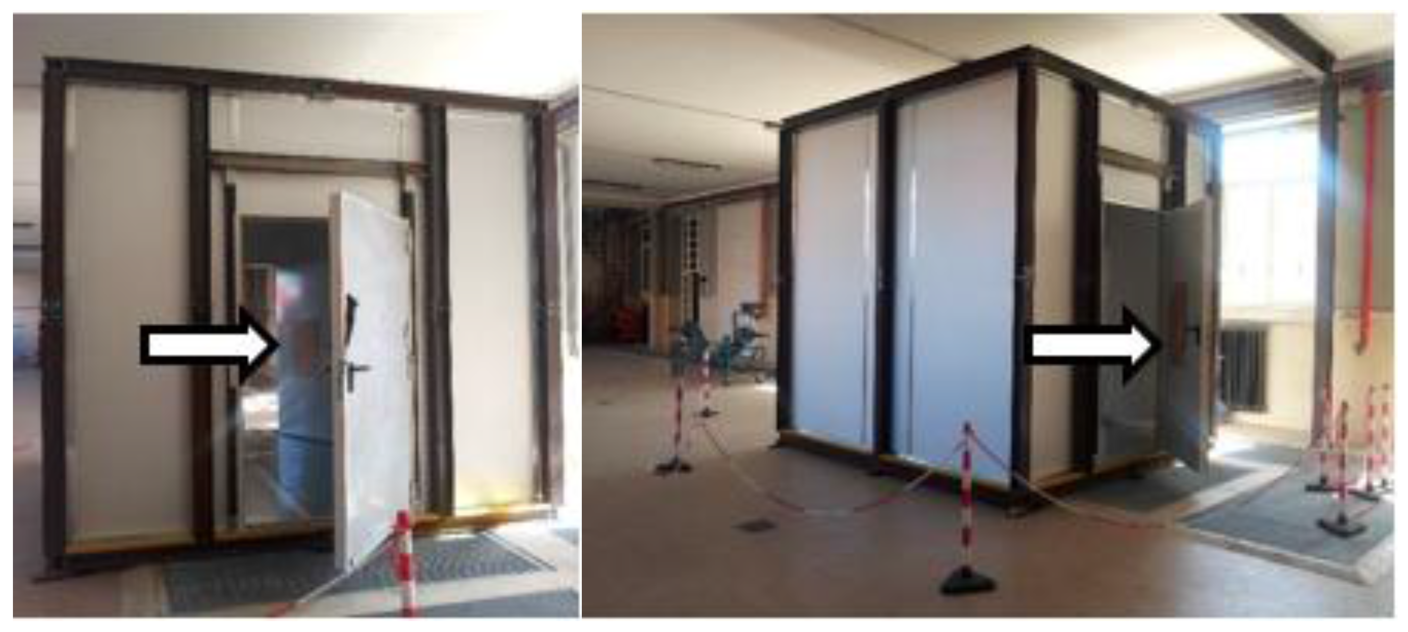
The experimental tests have been carried out in the Hydraulic Laboratory of the Central Directorate for the Prevention and Technical Safety of the Italian National Fire Rescue and Service. The pressurized enclosure test rig is a 3.0-m side cube with two identical single leaf doors. Each door is 1.0 m wide and 2.1 m high, and they are located on the front and on the rear wall enclosure sides. The front door swings inwards with respect to the enclosure in overpressure while the back door is opening outwards, coherently with the direction of the egress. Figure 3 shows the experimental smokeproof enclosure, highlighting the front and back door positions.
The walls and the doors are fire-resistant and ensure structural resistance and no spread of smoke and heat for the 60-min ISO 834 standard curve. The enclosure structure is a steel frame construction with a wooden floor covered by a metal sheet and walls and ceiling composed of assembling self-supporting double skin metal-faced insulating panels. Linear joints and gaps were sealed so that the air leakage is reasonably restricted through the edges of the doors. Inside the compartment, a helicoidal fan is placed at the left wall of the system (at a height of 2.2 m from the floor and a horizontal distance from the front wall of 2.1 m).
Due to geometrical constraints of actual smoke enclosure configurations, it is usually not possible to place the fan in a desired position, not even in a symmetric wall position. Therefore, the fan position has been chosen arbitrary and horizontally asymmetric on the side enclosure wall.
Considering the mechanical properties of the fan, five different levels of velocity can be manually selected for the fan, and the as-built system is able to reach 50 Pa of overpressure with maximum airflow of 1630 m3/h. The choice of the fan has been made according to the analytical design described in the previous section.
A testing campaign has been conducted to get functional information about the fluid dynamics behavior in a controlled environment representing a typical setup adopted in the Italian fire engineering practice (i.e., an enclosure to enter a protected stairwell). Several values of differential pressure up to 50 Pa in the enclosure have been generated varying the working fan velocity. As recommended in the NFPA 92, the tests are carried out without smoke, considering only fresh air. The first part of the experimental campaign consists of studying how the pressure varies in time, taking into account the decrease and increase pressure trend due to the opening and closing of entrance and exit doors. The pressure difference between the enclosure and the outside space is logged with a KIMO C310 data logger. A time step of 1 s is usually employed, unless an oscilloscope Tektronix TDS 210 is used to zoom in on the transitory phenomena of the pressure variation when the doors are opened or closed. Then, velocities across the doors are collected with an anemometer.
Specifically, the experimental apparatus consists of two pressure differential sensors, one anemometer and an oscilloscope. The pressure sensors measure the overpressure between the inside and the outside; they were placed initially at z = 1 m near the right lateral wall enclosure at a distance of 1 m among them (sufficiently far from the local effects of sublayer near-wall, as well as those caused by the air supply by the fan). During the experimental campaign, the position of the sensors was changed in order to verify the coherence of the pressure measurements.
The anemometer, instead, is fixed at different horizontal and vertical positions according to an interesting measurement. The measuring range of the instrument is 0–25 m/s, with a resolution of 0.1 m/s and an accuracy of ±3% for the reading ±0.1 m/s–3 m/s.
Initially the two doors are kept closed, and the fan is activated to reach the desired pressure level inside the enclosure. After the system is stabilized, different sequences are investigated. In the first sequence, only the front door is opened and closed after 30 s, while in the second sequence, the back door is opened and then closed, with the aim of qualitatively investigating whether the exiting airflow was stable and sufficient or not. In the third and last sequence, in order to simulate the egress of an occupant, the front door is opened and closed after 4 s, then the back door is opened after 2 s and closed after another 4 s. This sequence is considered as a reasonable time interval simulating the entering of an occupant inside the enclosure and of course in agreement with the automatic door closer systems commonly available. During each sequence, the fan is always kept running at a high velocity in order to achieve the fastest system response both during opening and closing of the doors. Table 3 contains a concise description of the tests, where D1 is the front door, D2 is the back door, c means that the door is closed, while o indicates an open door. No information about the pressure or the airflow is contained in the table since several series of tests are done by varying the operating velocity of the fan, although most of the tests allow reaching 40–50 Pa inside the enclosure.
To sum up, pressure measurements have been done with closed doors, while velocity (airflow) measurements have been done with open doors.
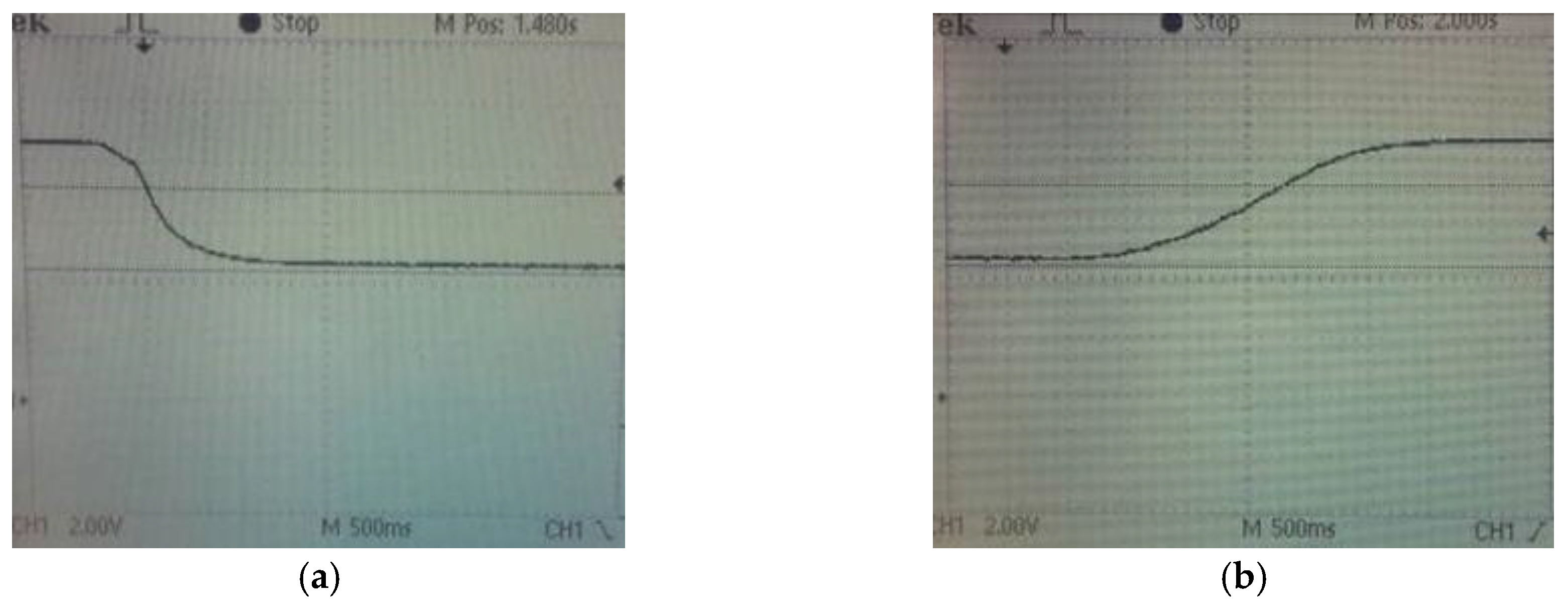
Figure 4 reports typical pressure profiles recorded by the oscilloscope during the transient phases. The oscilloscope is not digital; therefore, the figure is not very visible; however, the length scale of the signals on the screen is 500 ms, and the ordinate value is the pressure (scaled based on the maximum value). The first screenshot (A) displays the logged signal of the pressure decay in one test carried out when the front door is opened while the pressure inside the enclosure is 40 Pa. It takes about 1 s for the pressure to be relaxed (with the fan running). The second screenshot (B) displays the logged signal of the pressure rise in one test carried when the back door is closed and the fan is operating to establish 40 Pa inside the enclosure. In this case, it takes about 2 s to restore the pressurization set value.
For other tests with the fan working at its maximum velocity, the internal overpressure reaches 50 Pa, but the number of seconds to stabilize the system (both opening and closing the doors) does not change. As an example, Figure 5 depicts the pressure variation obtained performing Test 3 described in Table 3. Two lines (“+” and “–”) indicate the two sensors: the trends are essentially the same; only a slight delay can be noticed between them.
It is important to remark that pressurized enclosures are completely different from the pressurized stairwell for their strong sensitivity to the boundary conditions. The ratio of the pressurized volume/dimensions of the door is small, and so, are the decay to zero of the overpressure, and its restoration to the original value. Looking at Figure 5, it is clear that this aspect is positive because in 2 s, the overpressure reaches the maximum value starting from zero, but at the same time, the decay at the opening of the door is almost instantaneous.
Regarding the velocity of the air flux across the doors, large variability is found in the measurements caught by the anemometer. First, due to the lateral position of the fan, the resulting velocities across the doors have strong directional components, sometimes oscillating. Secondly, the distribution of the velocities is widely disperse, with higher values concentrated in the upper part of the door opening, as well as in the lower part very close to the floor, whereas in the central core of opening the air velocity is slower. The highest local values recorded are about 0.7–0.8 m/s, but most of the monitored points do not exceed 0.4 m/s. If the average velocity is compared with the recommendations in EN 12101-6 (0.75 m/s is the chosen threshold, due to the most similar application to the Italian fire engineering practice), the airflow requirement is not fulfilled.
5. CFD Simulations
The same domain is studied by CFD simulations, with the aim of improving the knowledge about velocities and comparing the results of experimental tests. The numerical code used is the fire dynamics simulator (FDS) [18,19] developed by NIST (National Institute of Standard and Technology, Gaithersburg, MD, USA). Version 6.2.0 has been used for this work.
FDS works under the low Mach number approximation, consistent with the typical range of pressure developing during fire conditions. According to this approximation, the total pressure is considered to be composed of a background component p1 plus a perturbation component p2. Most often, p1 is just the hydrostatic pressure, and p2 is the flow-induced spatially-resolved perturbation. The strength of the low Mach approximation is that the solving equations are expressed only in terms of the background pressures, eliminating the need to solve detailed flow equations within the ventilation ducts that do not influence the overall behavior of the phenomena.
For this kind of model, a number of pressure zones need to be specified (compartments within the computational domain with their own background pressure). These zones are connected via leakage and duct paths whose flow rates are tied to the pressure of the adjacent zones, giving good estimations in terms of dynamic pressure inside the domain.
5.1. Description of the Model
The model is built keeping the same geometrical dimensions of the experimental enclosure, as shown in Figure 6. The dimensions of the model are 5 m × 5 m × 5 m in the x, y and z directions. The grid size is cubic shaped and of 5 cm (commented on below), with a total number of 100 cells in the three directions. Boundary conditions for the most external vertical planes are “open” at atmospheric pressure. Measurement points will be explicitly specified before each graph, but are concentrated in the center of the enclosure for the pressure and across the doors for the velocity.
Since the simulations provide the presence of neither the fire source, nor hot smoke, the thermal properties of the materials are not significant for the results; however, the basic parameters are included in the model. Specific heat, conductivity and density are respectively 0.84 kJ/(kg K), 0.48 W/(m K) and 1440 kg/m3 for obstructions (walls, floor and roof level of the enclosure, including the doors).
The doors are modelled as obstructions. In FDS, the action of opening the door becomes simply the removal of the obstruction from the domain. The two zones of pressure (inside the compartment enclosure and external domain) are immediately connected, becoming a single zone, but the time to reach the equilibrium is calibrated through the pressure relaxation time function, using the value obtained by the oscilloscope in the experimental test (Figure 4). The case is the same for the closing of the door: as the obstruction is inserted in the model, FDS reads two different pressure zones instead of one, with the consequence of the instantaneous rise of the internal pressure (in this case, FDS seems to be unable to increase the transitory phase, even changing the value of the pressure relaxation time). Specifically, the pressure relaxation time in FDS is set to 1 s for the case in which the door is opened, while 2 s are chosen for the closing case (although irrelevant because it does not affect the output of the simulations).
Another way of removing the obstruction (partially, dividing the door in more sub-obstructions to be removed one after the other) would not have led to improvement of the results, since the behavior of the model is linked to the “pressure zones” solver. Clearly, although a similar example is contained in the FDS Guide [19], the instantaneous removal of the door-obstruction seems to be quite different from the door swinging open. On the other hand, the accuracy of this feature in terms of pressure is guaranteed through the calibration of the pressure relaxation time based on real data collected with the help of the oscilloscope.
The model of the fan is a simple air supply blowing air at a constant airflow as in the experimental enclosure, considering the nominal value of the airflow. The work in fact does not take into account the hydraulic losses of the fan and does not consider the actual external “pressure versus air flow” output fan curve.
The size of the mesh has been chosen after calibration and sensitivity analysis. Considering that the flow field originates from a 40 cm × 40 cm inlet surface, a 5-cm side cubic mesh seems to be sufficiently fine to correctly predict the air movement in the domain. As the boundary conditions of the pressure are much more complicated than the usual features typical of FDS, the influence of the extension of the surrounding domain is investigated, in order to understand whether the cycle of opening and closing doors changes the results. Looking at the pressure reached inside and the distribution of the velocities exiting the door when opened, extending the limit of the model up to 1 m more than the horizontal boundaries of the enclosure is a good compromise between the quality of the results and the computational effort. In the vertical direction, the domain is extended up to 2 m beyond the roof in order to keep an overall cubic domain with a side of 5 m.
The leakage through the doors is inserted in the model through a localized leakage function. The leakage through the edges of doors is a phenomenon whose order of magnitude is the millimeter. Therefore, indirect modeling through an HVAC function is used to represent airflow through a certain leakage area by explicitly defining the internal and external vents; in this way, FDS identifies leak paths where the air flows reaching a dynamic equilibrium between the zones. Therefore, for each edge, two vents are defined (internal and external, respectively confining the inside and the outside of the enclosure, thus belonging to two different pressure zones) and linked through an HVAC function (TYPE_ID = ‘LEAK’) whose area is defined through the calibration of the numerical results with the trend obtained by experimental tests.
This function is inserted for both the doors through the four boundaries of the obstructions: each door is bounded from thin vents (with a thickness of 5 cm) along the perimeter, and every vent (horizontal or vertical) identifies a leak path. The quantity of airflow lost through these vents depends on the area defined inside each vent, the value chosen so that the internal pressure stabilizes at 50 Pa as in the final series of tests. This is an indirect way to consider the leakage, but is functional for the purposes of this study: as the leakage works only when doors are closed, the interest is maintaining the pressure at the required level, and so, the balance of the airflows (in and out) is the key. Figure 7 depicts the calibration curves of the modelled leakage.
The series of tests considered for the calibration of the model are only those reaching 50 Pa, which are the only ones used for the comparison with the numerical results, as is reported in the next section. The test series reaching 40 Pa was initially used only to run a preliminary set of experimental results; the trends are actually very similar, because the dynamics of the system is quite fast, although the maximum overpressure is different due to the different working velocity of the fan.
Another hypothesis behind this approach is that the leakage is uniformly distributed through the external perimeter of the doors (another assumption could have been to localize all of the leakage in the horizontal lower part of the doors): as already stated before, detailed analysis of the leakage is beyond the scope of this study. In Figure 8, two slices (horizontal, crossing the lowest edge and vertical, crossing the right edge of the front door) of the velocity field are represented, showing also the effect of the localized leakage function.
5.2. Comparison between Numerical and Experimental Results
The fundamental three tests described in Section 4 and Table 3 are studied with FDS. Globally, the results of the numerical simulations seem to closely match the overall phenomenon, from the development of the air patterns inside the enclosure to the maximum overpressure reached and the distribution of velocities across the doors.
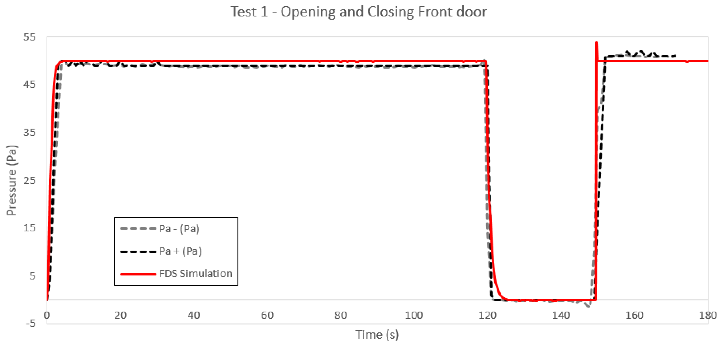
In Figure 9, the trend of the pressure in time is represented both for the numerical simulation and actual data recorded during Test 1. The lines overlap during all phases, apart from the very last 20 s of the test, probably because of a fluctuation in the working of the fan. There are two dashed lines (“+” and “–”) for the experimental trend because there are two pressure differential sensors, but in line with the scalar nature of the pressure, the recorded values are the same.
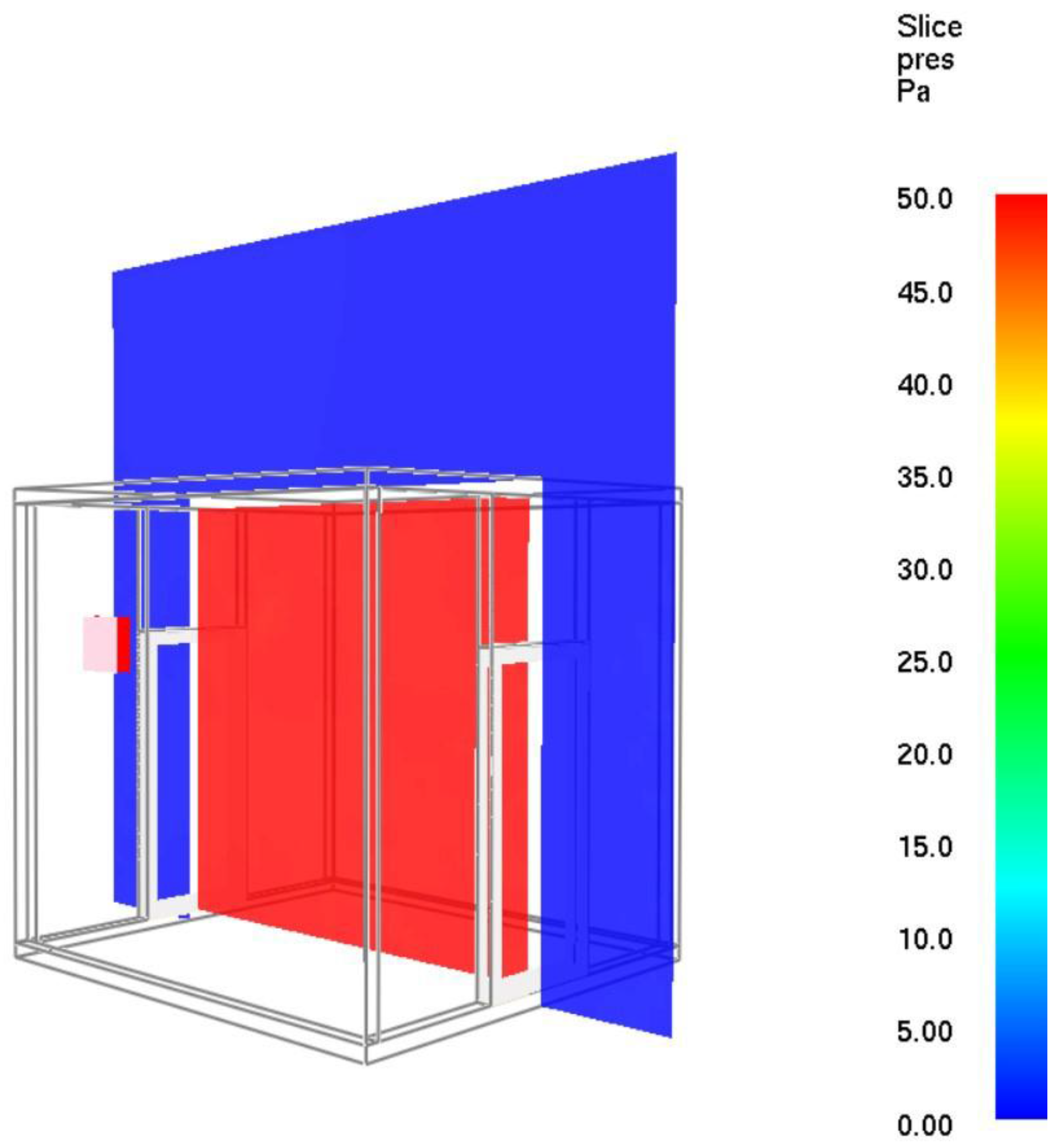
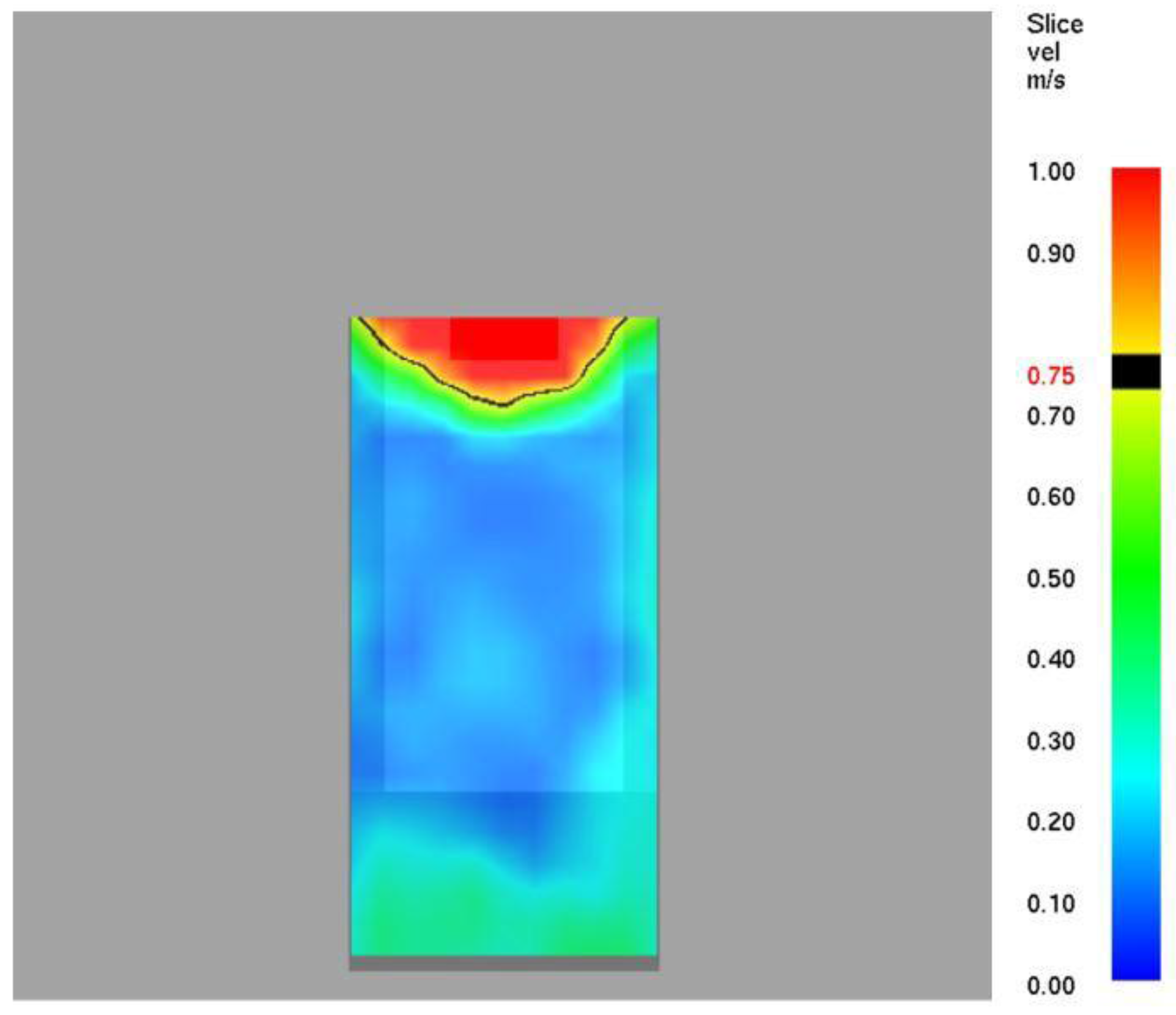
Coherently in Figure 10, the contour of the pressure along a slice of the FDS simulation shows a homogeneous value of the pressure for all of the domain. As previously stated, the homogeneity is due to the pressure zones’ modeling implemented in FDS. The slice is taken with a closed door, after the pressure is stabilized.
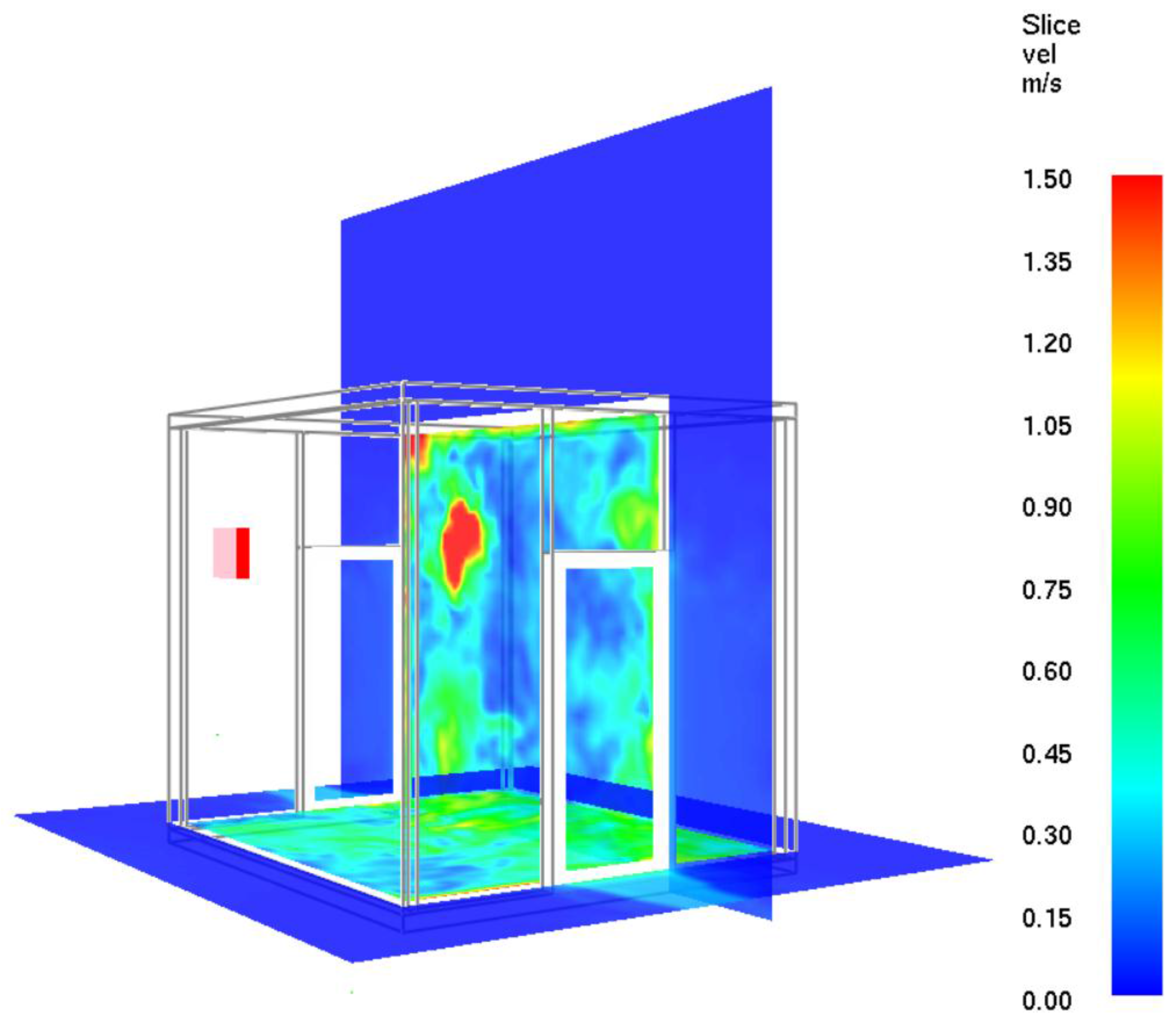
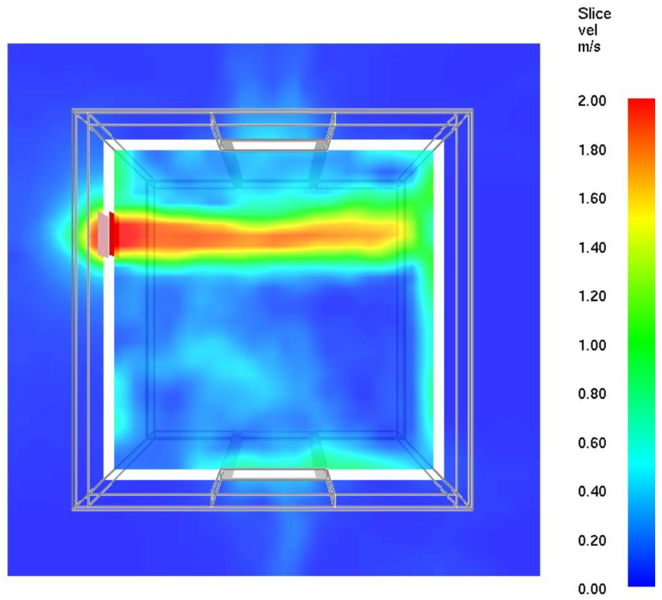
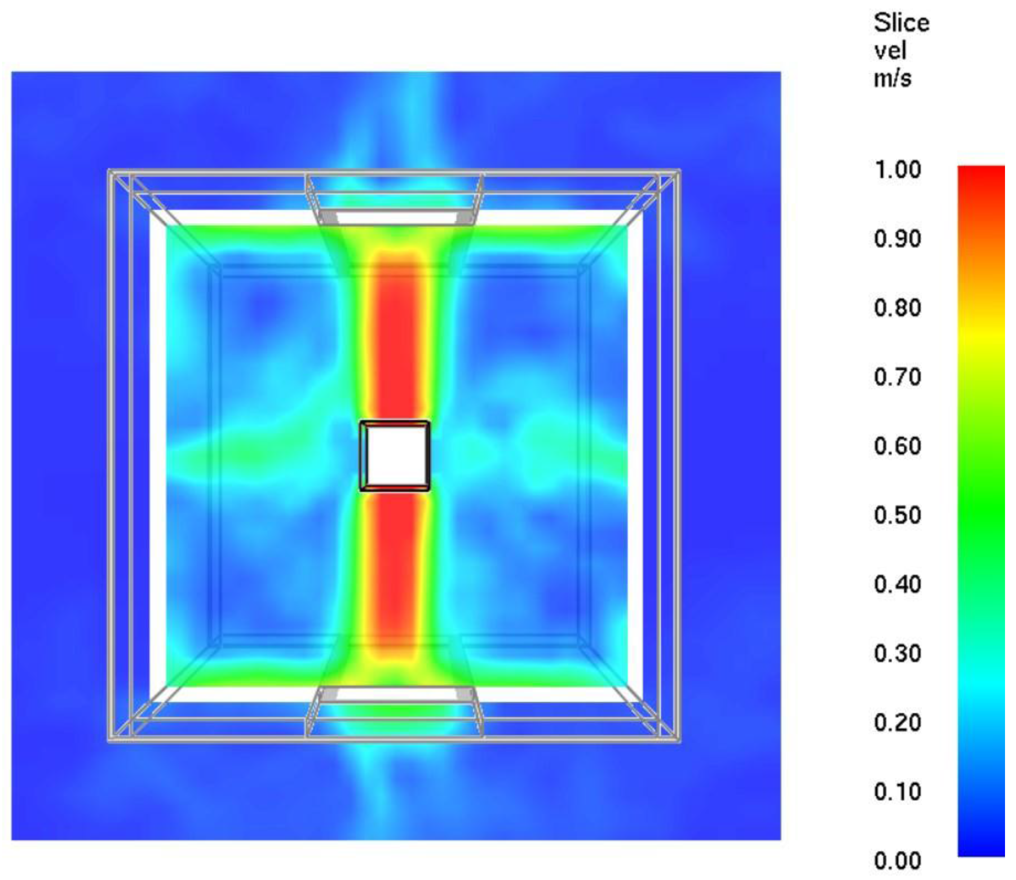
Then, the working of the system from the point of view of the velocity of the air is investigated. Firstly, in Figure 11, an instantaneous screenshot of the velocity field caused by the air supply is shown. The slice cuts the domain at z = 2.2 m (the middle height of the fan): the air is pushed with a maximum velocity of 3 m/s to the opposite wall, where the flow slips along the walls until it reaches the doors (and so, the leak paths). Due to the horizontally-asymmetric position of the fan, higher velocities are concentrated close to the back door, especially in the upper part (at the level of the fan). The awareness of this effect, since the study is intended to assess the operational conditions of the pressurized smokeproof enclosure, leads to paying attention mostly to what happens on the front door, from which the smoke could enter in case of fire.
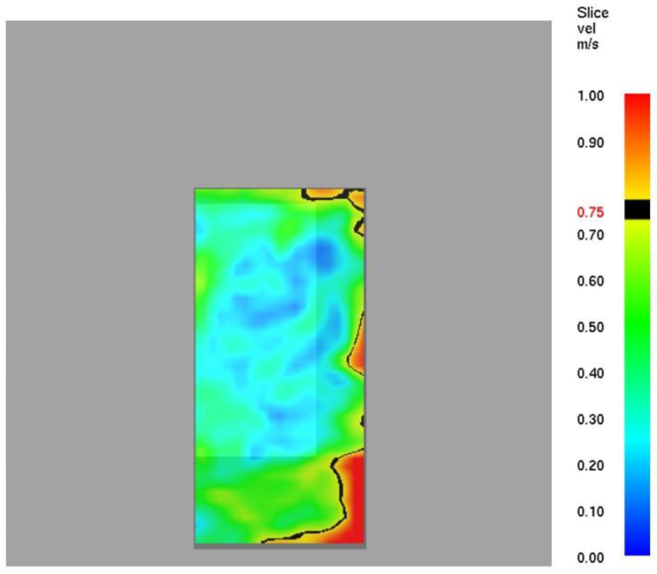
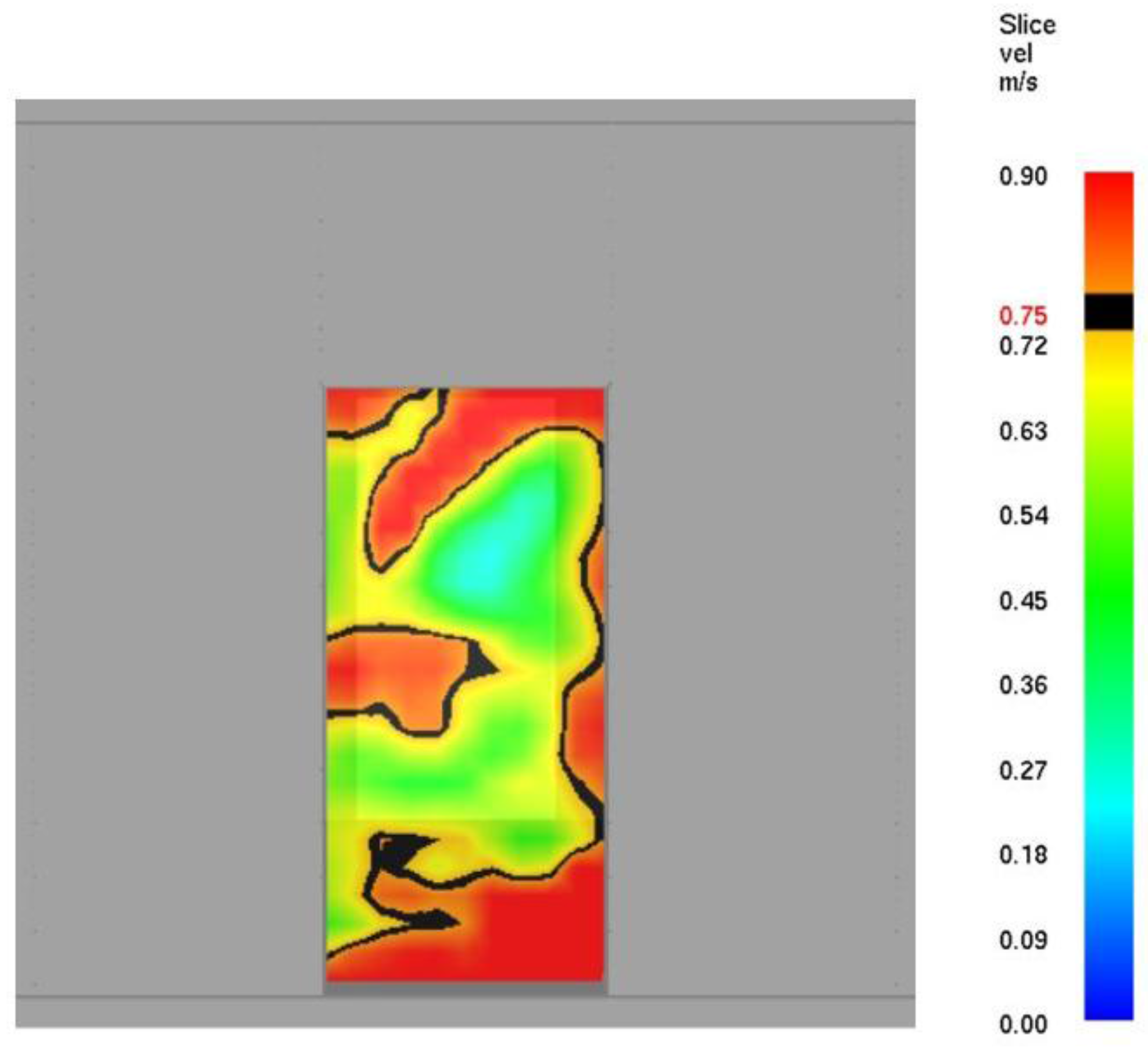
In Section 4, it has been stated that large variability affects the velocity distribution across the front door, with values not satisfying the requirement of EN12101-6. The numerical simulation confirms this assumption. In Figure 12, the velocity slice (located at the cross-section of the front door as viewed by an incoming occupant) shows that velocities are far from being uniform both in the modules and in the directions. Values are low, especially in the center of the door, while a sort of slip along the internal walls makes the air exit mostly from the right side of the door itself.
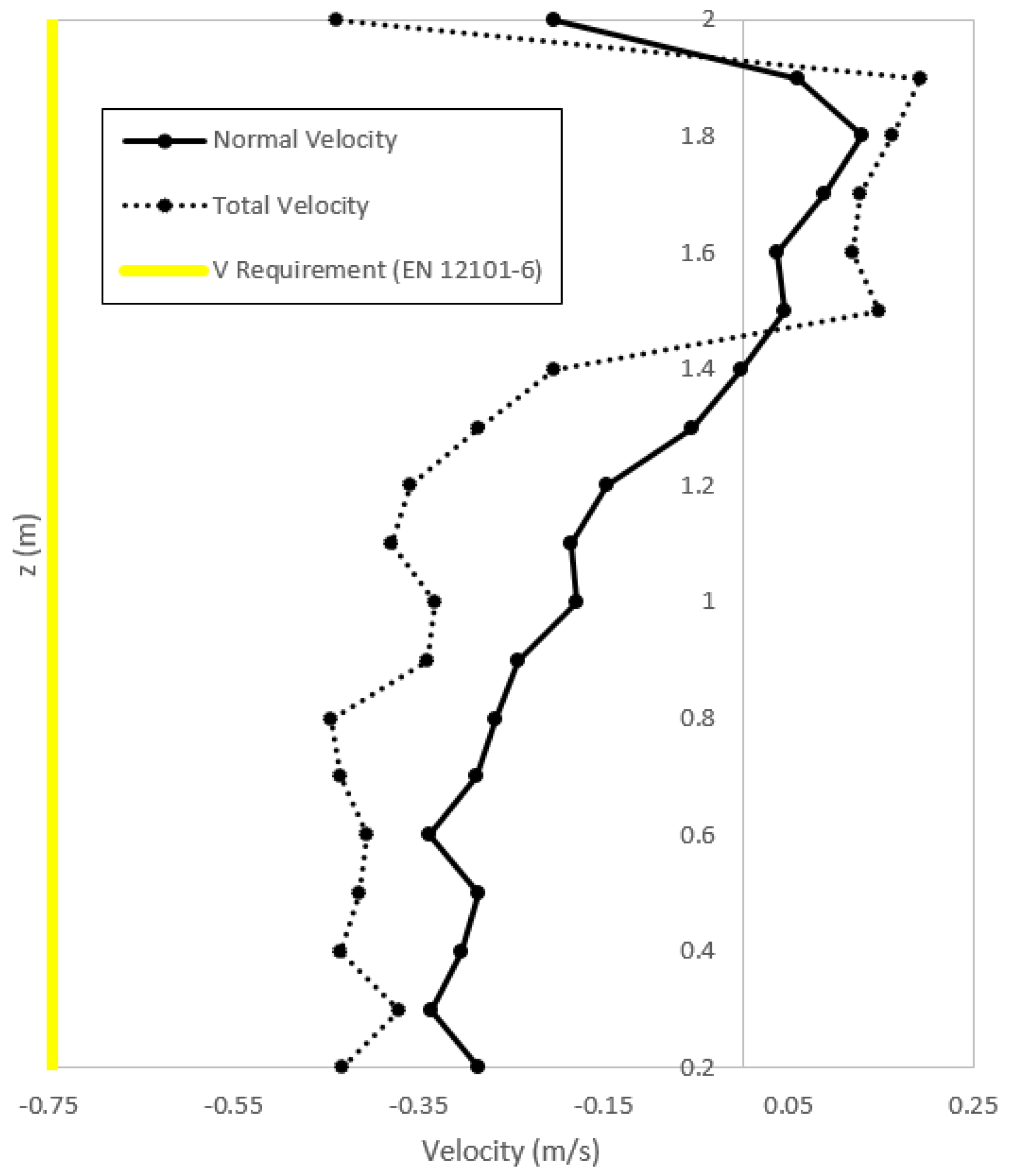
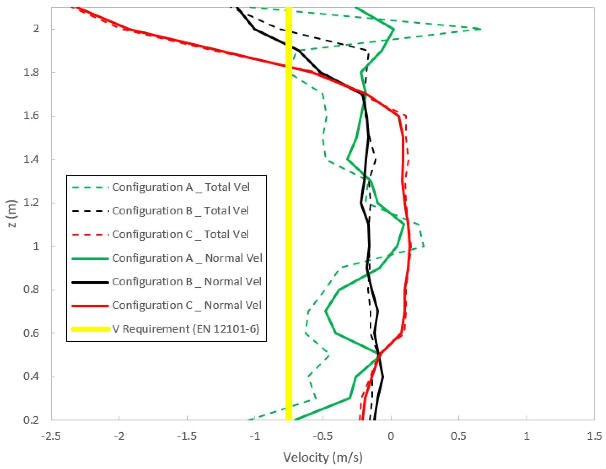
Considering the central axis of the cross-section across the front door, a velocity profile built-up by interpolating FDS punctual numerical measurements is drawn in Figure 13. Only FDS predicted velocities are shown because experimental measurements were too close to the resolution of the anemometer and are not reported. Since the velocities are highly fluctuant as typical of the LES (large eddy simulation) solver and fine mesh, each represented value is obtained by an average of three different close monitored points (at a relative distance of 5 cm in the thickness of the door). As velocity is a vector, according to the axis definition shown in Figure 6, negative and positive values in the profile are meaningful in understanding if the airflow is actually exiting the door or ineffectively recirculating into the enclosure. The continuous line is the normal component of the velocity (labelled “normal velocity”, negative in the outwards direction), while the dotted line is the whole velocity (called “total velocity”, that is the module ||v||, but preserving the sign of the normal component to facilitate the understanding of the direction). The difference between them is a measure of how much of the airflow is directed orthogonally to the door section. In fact, the EN12101-6 does not specify whether the minimum velocity requirement is related to the total or normal component of the velocity, but the normal component should be the most efficient to contrast the entrance of smoke compared to the transversal and the longitudinal components. However, the limit of 0.75 m/s is not reached: higher velocities are concentrated at the boundaries, while between 1.5 m and 1.9 m, there is also an internal circulation of air.
5.3. Considerations
Based on the FDS simulations, the following considerations can be done.
Firstly, as expected, the system does not comply with the EN12101-6 requirements because the velocity of the airflow is not fulfilled. This is not a surprise: the fan has been designed and chosen only considering the pressure criterion. Even if the installed (and thus modelled) fan is oversized in terms of airflow (1630 m3/h instead of 1050 m3/h), the simulation results confirm that this is not enough to assure an acceptable average velocity through open doors.
Secondly, the absence of symmetry in the horizontal position of the fan (the fan position is nearer the back door instead of a more appropriate position closer to the front door) has a significant effect on the distribution of the velocities. Furthermore, since the fan is placed in the left lateral wall of the enclosure, it blows air towards the right wall instead of directly hitting the front door, causing internal circulation of the air and unavoidable loss of the efficiency of the smokeproof enclosure.
Lastly, the fan is not equipped with the control system to adjust the inlet airflow according to the operational conditions. The consequence of the constant air supply is that when doors are closed, it is more than strictly necessary that the airflow reach the minimum design pressure, whereas when one door is opened, the airflow is not enough to guarantee a well-defined level of velocity across the doors.
Following the previous considerations, in the next section, some possible alternative solutions are proposed and studied from the numerical point of view, trying to identify which are the negative aspects of the experimental enclosure that mostly influence the non-uniform distribution of the velocity, that is the position of the fan rather than insufficient airflow when doors are opened.
6. Alternative Configurations
Three alternative basic configurations of a pressurized smokeproof enclosure are studied from the numerical point of view with the purpose of showing the most influential aspects (parameters, values, operational conditions) to be taken into account during the design process of pressurization systems. Some of the following configurations are far from being found in buildings; however, they can represent a benchmark for the selection of convenient solutions.
Configuration A is identical to the basic configuration, but equipped with a fan injecting controlled variable airflow: in FDS, the chosen HVAC model provides a parabolic growth of the airflow in time, fixing the maximum value of the reachable overpressure to 50 Pa and a maximum air supply of 3260 m3/h (exactly double the airflow of the basic case). The value of about 3000 m3/h is typical for Italian commercial pressurization kits of smokeproof pressurized enclosures.
Configuration B instead is an enclosure with the same fan injecting constant airflow (1630 m3/h), but placed so that the air supply is directed frontally towards the doors. The fan is at the same height of the basic configuration, but placed centrally in the enclosure, and the total airflow is split into two halves directed towards the front and the back door. The maximum overpressure is 50 Pa (the total airflow has not changed), but the internal distribution of velocity is different due to the new type of inlet and the more symmetrical configuration.
Finally, Configuration C is intended to provide the same airflow of the basic configuration, but only towards the front door, with the aim of reducing dispersion in inner circulating air and increasing efficiency in the air velocity profile of open doors.
In Figure 14, Figure 15, Figure 16, Figure 17, Figure 18 and Figure 19, slices of relevant fields of velocity are reported for Configurations A, B and C.
In Configuration A, the distribution of velocities when doors are closed (Figure 14) is not regular as in Configurations B and C (Figure 16 and Figure 18), but when the front door is opened (Figure 15), the fan is able to increase its airflow, resulting in a good distribution of velocities across the whole front door. In Configuration B, instead, the highest velocities are localized only in the upper part of the door (Figure 17), but the values are too low: the total airflow is divided between two opposite directions, and this solution appears to be inefficient (the injection of the total airflow towards the front door would have resulted in better distribution of velocities). Configuration C provides higher velocities compared to Configuration B (Figure 19).
In Figure 20 and Figure 21, the velocity profiles for the three configurations show that for Configurations B and C, the normal component of the velocity almost contributes the overall velocity, but the airflow is too low. On the other hand, for Configuration A, there is a waste of efficiency due to the lateral inlet, but the variable airflow compensates this aspect, resulting in higher peripheral velocities; nevertheless, in the center line, the velocities are still not fulfilling the requirement of EN 12101-6. Furthermore, looking at the vertical profile of Configuration C, some effects of internal air circulation appear, with air exiting from the upper part of the opening and air entering the lower part.
7. Conclusions
The paper reports the design and construction of a smokeproof enclosure based on the pressure design criteria. The actual pressurized smokeproof enclosure is studied and characterized through several experimental tests, focusing mainly on the dynamic equilibrium that the system develops once the maximum overpressure is reached. Cycles of opening and closing doors show that, due to its dimensions, the system reacts quickly to changes of the boundary conditions. Specifically, it is highlighted that starting from a level of 50 Pa inside the enclosure, the decay of the overpressure to zero appears instantaneous when the front door is opened, while once the door is closed, the overpressure is restored to its original value in about 2 s. The strength of this kind of pressurized systems is indeed the fast dynamics of the transient phase. Considering the ease of restoring the initial overpressure, the smokeproof enclosure can be defined, in a certain sense, as a “resilient system” during the egress phase and thus during the door opening/closing cycle. Furthermore, its ability to disconnect two different compartments (the hypothetical fire floor compartment and protected stairwell) implies the need for the extremely powerful fan typical of pressurized stairwells.
Regarding the velocities across the front door, the chosen smokeproof enclosure configuration does not meet the requirement of EN 12101-6. This aspect is modelled and investigated by means of a detailed FDS model, also tuned on the basis of experimental data. What emerges is that the position of the fan is not efficient, as well as the nominal value of its airflow. Even if the paper focuses only on small pressurized compartments, it must be highlighted that the difficulty with respect to the velocity requirements can be considered as a problem for all types of pressurized systems, from smokeproof enclosures to stairwells and shafts.
With the help of numerical analysis, alternative configurations are proposed identifying the advantages and disadvantages based on velocity profiles in the center line of the front door and velocity field at relevant sections. The apparent simplicity of the system shows how many difficulties can be encountered to fulfill airflow requirements in open door conditions. The other limitation of the work is the absence of a fire source in both experimental tests and models, with the unavoidable consequence of not considering buoyancy effects typical of hot toxic gases able to modify air flow in the interface layer. Nevertheless, the choice of the authors is in agreement with NFPA 92, which recommends cold tests for the assessment of smokeproof enclosure functionality and operating conditions.
Even though a more detailed HVAC model could have been chosen, considering for example a user-defined fan curve, qualitative results and experimental data seem to be sufficient to highlight how crucial is the design of the air supply fan for this kind of fire safety system.
Acknowledgments
The authors thank the Central Directorate for the Prevention and Technical Safety of the Italian National Fire Rescue and Service for the help in the development of the experimental tests.
Author Contributions
In each section of this paper the authors made equal contributions.
Conflicts of Interest
The authors declare no conflict of interest.
References
- Fire Statistics: Great Britain April 2013 to March 2014, Ref: ISBN 9781409842118. Available online: https://www.gov.uk/government/statistics/firestatistics-great-britain-2013-to-2014 (accessed on 1 September 2016).
- Purser, D.A. The effects of fire products on capability in primates and human fire victims. Fire Saf. Sci. 1986, 1, 1101–1110. [Google Scholar] [CrossRef]
- Purser, D.A. Modelling toxic and physical hazard in fire. Fire Saf. Sci. 1989, 2, 391–400. [Google Scholar] [CrossRef]
- Purser, D.A. Dependence of modelled evacuation times on key parameters and interactions. Fire Saf. Sci. 2008, 9, 353–364. [Google Scholar] [CrossRef]
- Magdanz, C.E.; Klote, J.H. An overview to designing smoke-control systems. ASHRAE J. 2002, 44, 32–41. [Google Scholar]
- Hurley, M.J.; Gottuk, D.T.; Hall, J.R., Jr.; Harada, K.; Kuligowski, E.D.; Puchovsky, M.; Torero, J.L.; Watts, J.M., Jr.; Wieczorek, C.J. (Eds.) SFPE Handbook of Fire Protection Engineering, 5th ed.; Springer: New York, NY, USA, 2015. [Google Scholar]
- Lay, S. Pressurization systems do not work and present a risk to life safety. Case Stud. Fire Saf. 2014, 1, 13–17. [Google Scholar] [CrossRef]
- Youa, W.J.; Kob, G.H.; Ryoua, H.S. A study on the unsteady flow characteristics in a vestibule for an injection and pressurization smoke-control system. Fire Saf. J. 2014, 70, 112–120. [Google Scholar]
- Bellido, C.; Quiroz, A.; Panizo, A.; Torero, J.L. Performance assessment of pressurized stairs in high rise buildings. Fire Technol. 2009, 45, 189–200. [Google Scholar] [CrossRef]
- Klote, J. The ASHRAE design manual for smoke control. Fire Saf. J. 1984, 7, 93–98. [Google Scholar] [CrossRef]
- Tamura, G.T.; Klote, J.H. Experimental fire tower studies on mechanical pressurization to control smoke movement caused by fire pressures, fire safety science. In Proceedings of the Second International Symposium, Siena, Italy, 14–16 June 1989; pp. 761–769. [Google Scholar]
- Hepguzel, B. Numerical and experimental investigation of pressurization system in a high-rise building with stairwell compartmentation. In Proceedings of the 2nd Asia Conference of International Building Performance Simulation Association (Asim 2014), Nagoya, Japan, 28–29 November 2014; pp. 99–106. [Google Scholar]
- Decreto 3 agosto 2015, Approvazione di norme tecniche di prevenzione incendi. Available online: http://www.gazzettaufficiale.it/eli/id/2015/08/20/15A06189/sg (accessed on 1 September 2016).
- British Standards. BS EN 12101-6: Smoke and Heat Control Systems—Specification for Pressure Differential Systems-Kits; British Standards: London, UK, 2005. [Google Scholar]
- NFPA 92: Standard for Control Smoke Systems; National Fire Protection Association: Quincy, MA, USA, 2015.
- NFPA101 Life Safety Code; National Fire Protection Association: Quincy, MA, USA, 2015.
- Butcher, E.G.; Parnell, A.C. Smoke Control in Fire Safety Design; E. and F.N. Spon Ltd.: London, UK, 1979; pp. 107–170. [Google Scholar]
- McGrattan, K.; Hostikka, S.; Floyd, J.E.; Baum, H.R.; Rehm, R.G.; Mell, W.; McDermott, R. Fire Dynamics Simulator (Version 6) Technical Reference Guide, NIST Special Publication 1018-5; National Institute of Standards and Technology: Gaithersburg, MD, USA, 2014. [Google Scholar]
- Mc Grattan, K.B.; Hostikka, S.; Floyd, J.E.; Baum, H.R.; Rehm, R.G.; Mell, W.; McDermott, R. Fire Dynamics Simulator (Version 6) Users Guide, NIST Special Publication 1019-5; National Institute of Standards and Technology: Gaithersburg, MD, USA, 2014. [Google Scholar]
Figure 1.
Pressurized smokeproof enclosure.
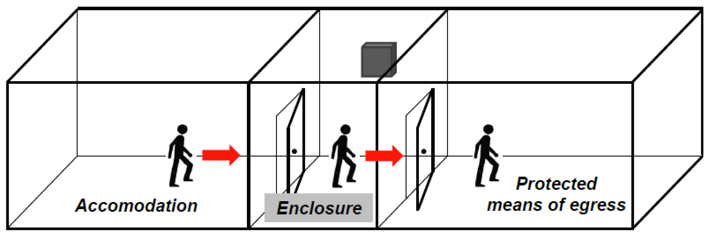
Figure 2.
Comparison between different (a) Class C and (b) Class E from EN12101-6.
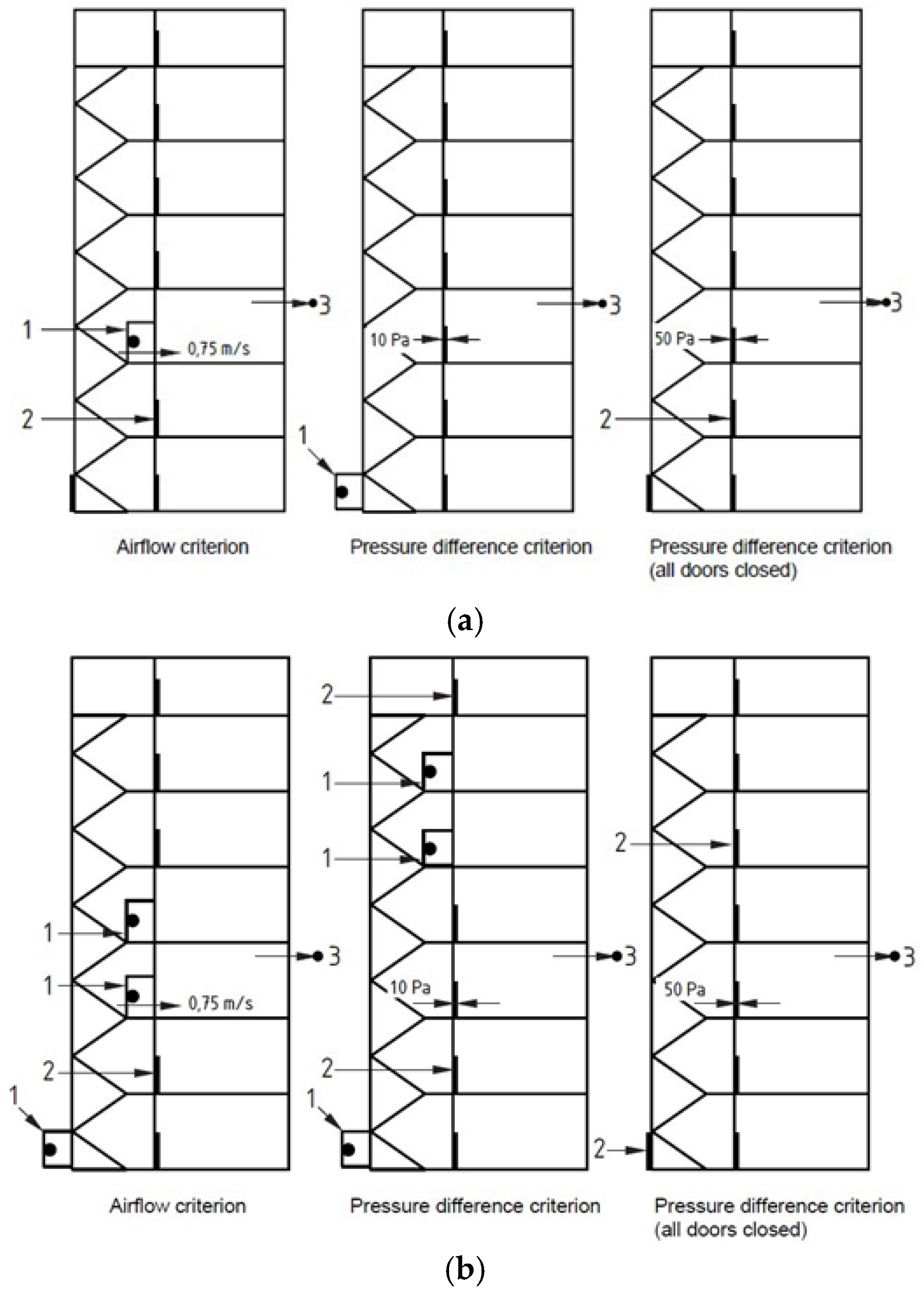
Figure 3.
Experimental smokeproof enclosure (front and back door opening, respectively inwards and outwards).
Figure 3.
Experimental smokeproof enclosure (front and back door opening, respectively inwards and outwards).

Figure 4.
Relaxation pressure time logged during (a) one door opening and (b) closing phase.

Figure 5.
Pressure variation in Test 3.
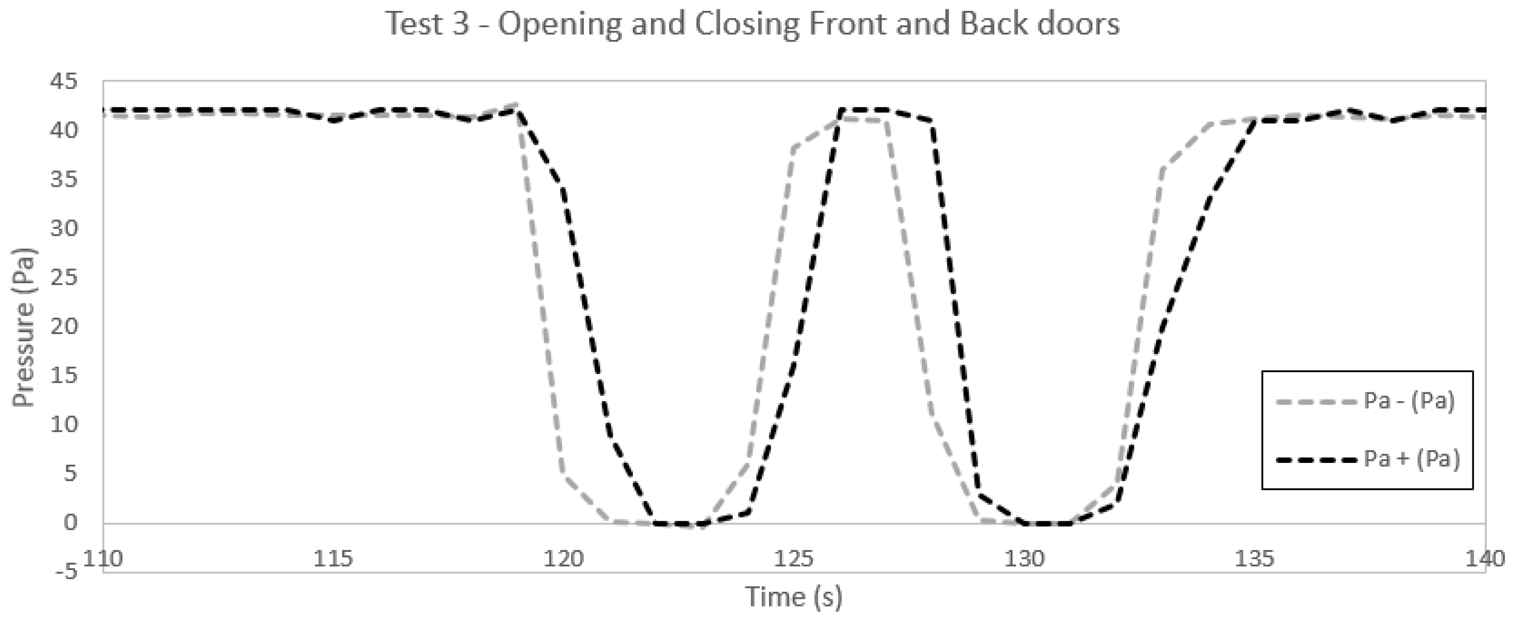
Figure 6.
Screenshot of the FDS model.
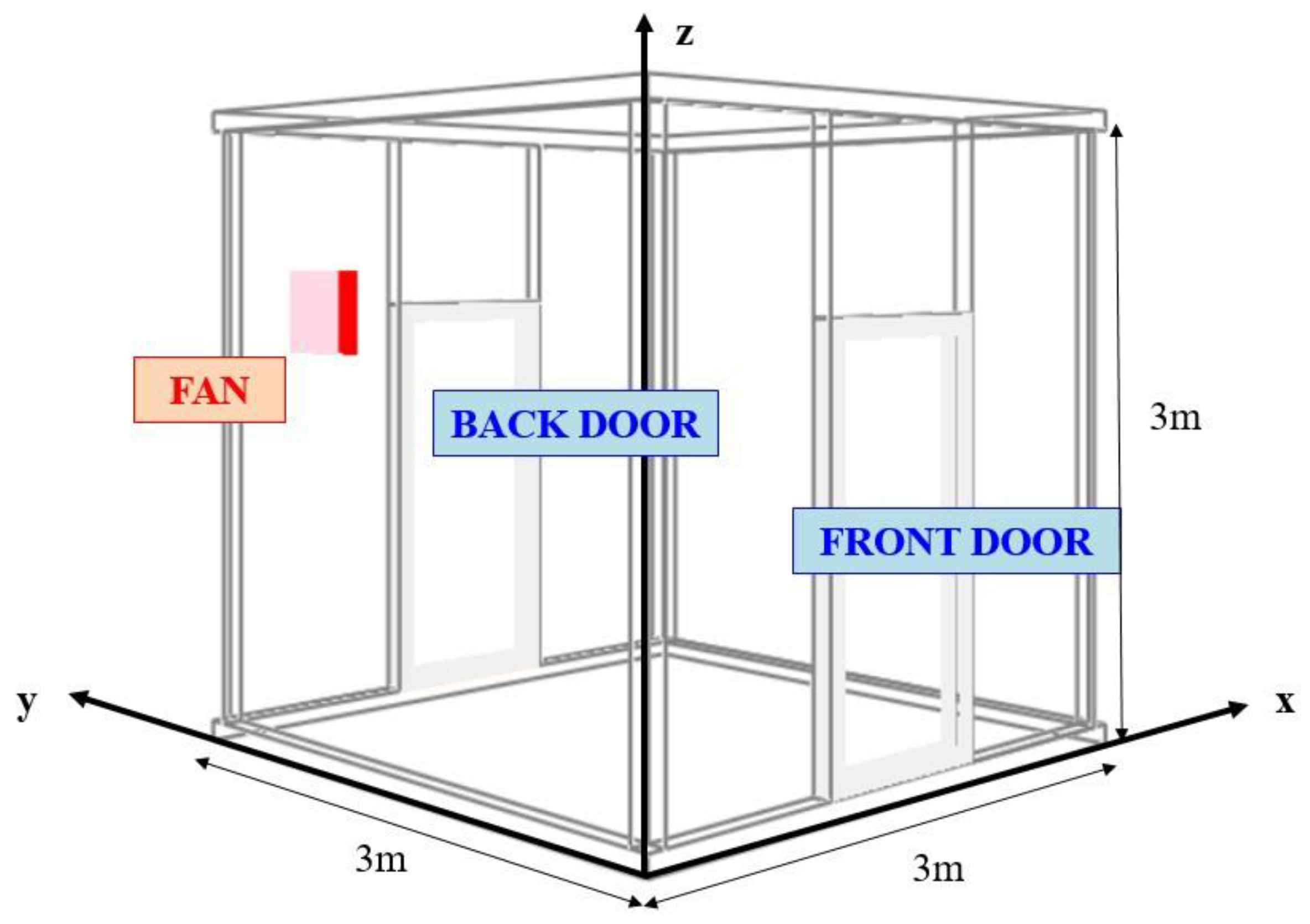
Figure 7.
Calibration of the leakage.
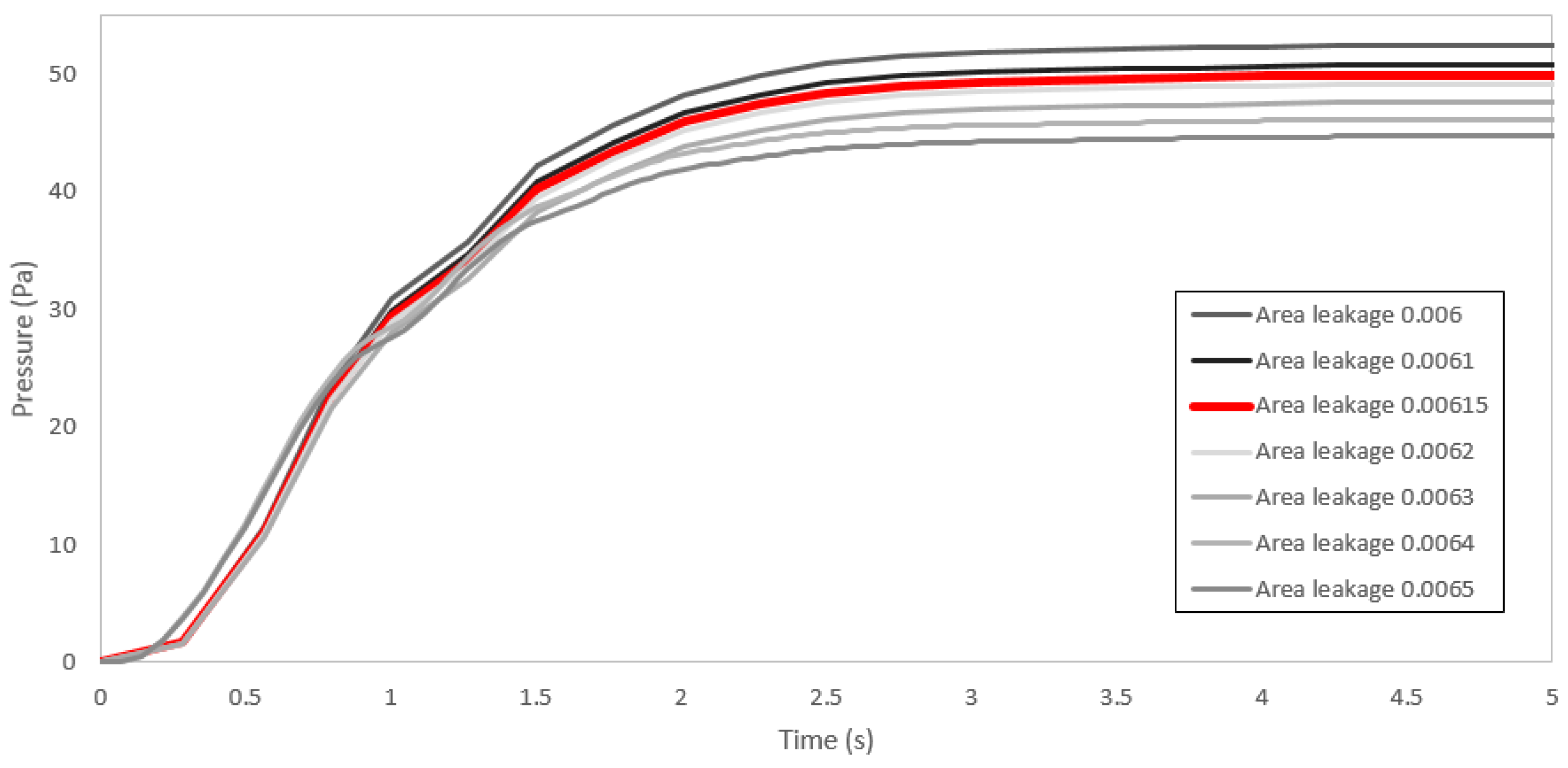
Figure 8.
Vertical and horizontal slices of velocity (“vel”) showing localized leakage through the front door.
Figure 8.
Vertical and horizontal slices of velocity (“vel”) showing localized leakage through the front door.

Figure 9.
Trend of the pressure in time during Test 1.

Figure 10.
Pressure contours in the central vertical plane (closed doors).

Figure 11.
Velocity slice at z = 2.2 m (closed doors).
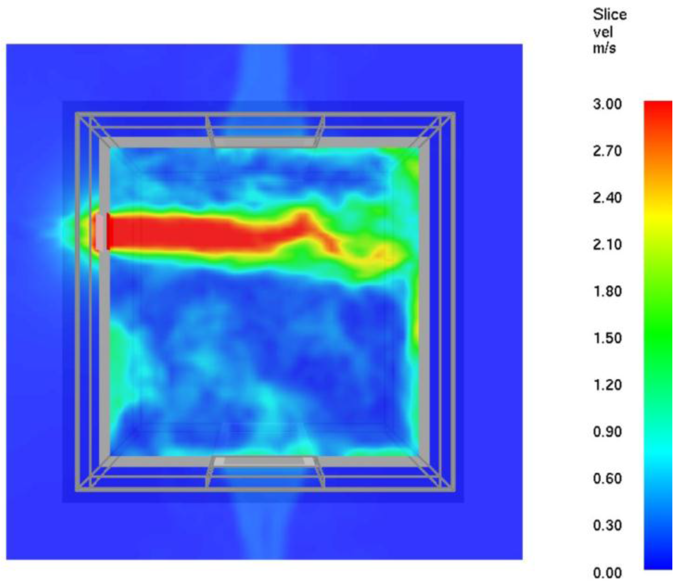
Figure 12.
Velocity slice across the front door at t = 130 s during Test 1 (front door opened).

Figure 13.
Velocity profile in the centerline of the door at t = 145 s during Test 1 (front door opened).
Figure 13.
Velocity profile in the centerline of the door at t = 145 s during Test 1 (front door opened).

Figure 14.
Velocity slice for Configuration A at z = 2.2 m (closed doors).

Figure 15.
Velocity slice at t = 130 s for Configuration A (front door opened).

Figure 16.
Velocity slice for Configuration B at z = 2.2 m (closed doors).

Figure 17.
Velocity slice at t = 130 s for Configuration B (front door opened).

Figure 18.
Velocity slice for Configuration C at z = 2.2 m (closed doors).
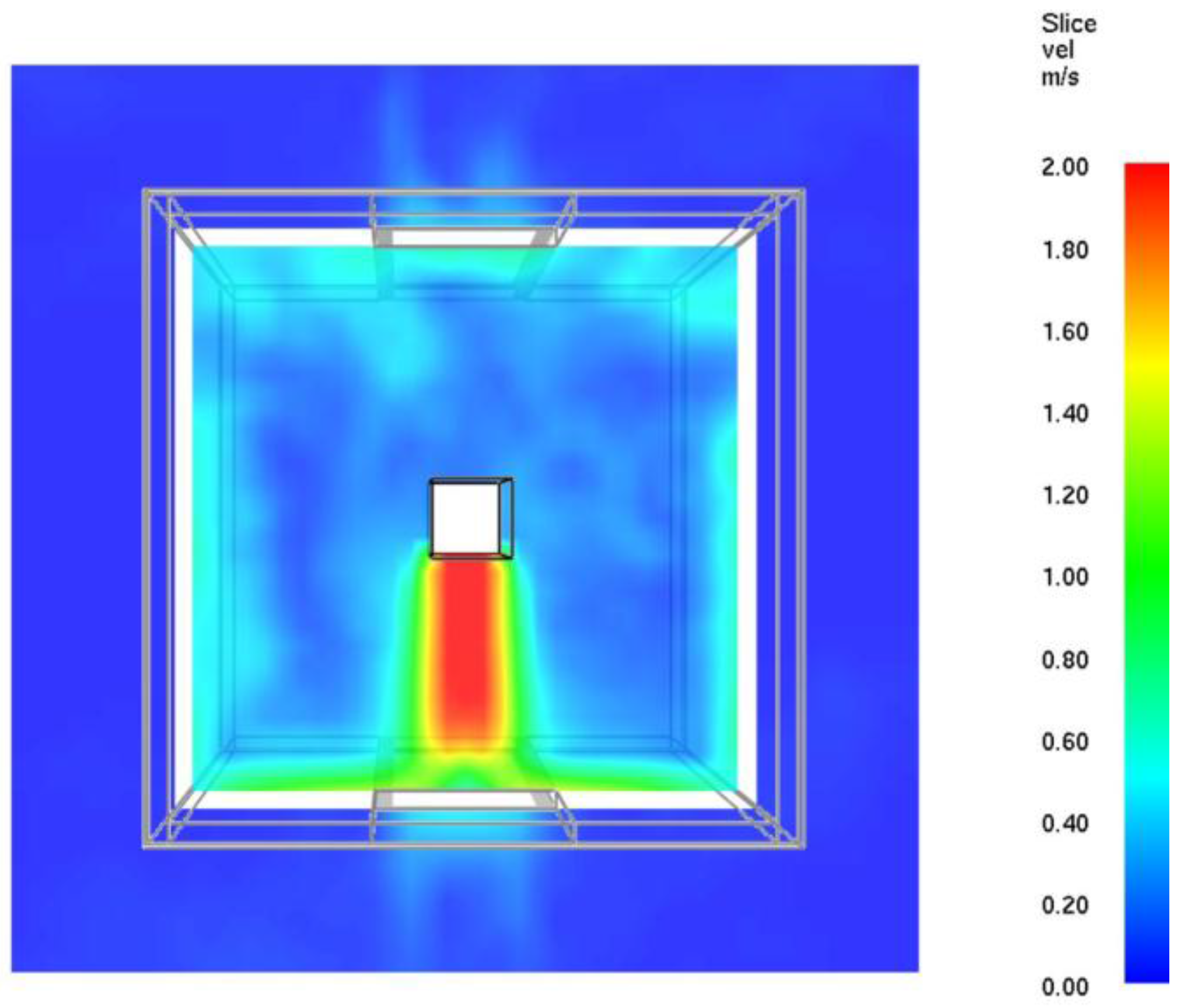
Figure 19.
Velocity slice at t = 130 s for Configuration C (front door opened).

Figure 20.
Velocity profiles in the centerline of the door at t = 125 s (front door opened).
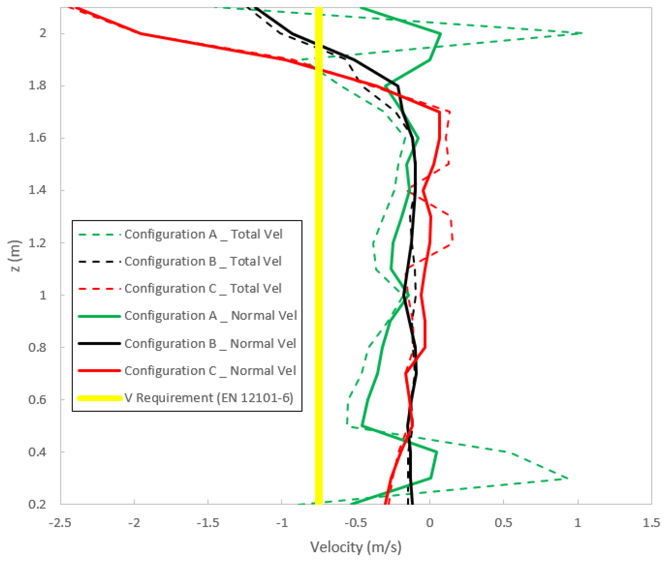
Figure 21.
Velocity profiles in the centerline of the door at t = 145 s (front door opened).


Table 1.
Requirements of class systems (EN12101-6).
| Class System | Strategy | Airflow | Pressure | Door Handle Force |
|---|---|---|---|---|
| A | For means of escape; defend in place | 0.75 m/s | 50 Pa | 100 N |
| B | For means of escape and firefighting | 2 m/s | 50 or 45 Pa | 100 N |
| C | For means of escape by simultaneous evacuation | 0.75 m/s | 50 or 10 Pa | 100 N |
| D | For means of escape; sleeping risk | 0.75 m/s | 50 or 10 Pa | 100 N |
| E | For means of escape by phased evacuation | 0.75 m/s | 50 or 10 Pa | 100 N |
| F | Firefighting and means of escape | 2 or 1 m/s | 50 or 45 Pa | 100 N |
Table 2.
Design pressure difference across smoke barriers (NFPA 92).
| Building Type | Ceiling Height | Design Pressure Difference |
|---|---|---|
| Sprinklered | Any | 12.5 Pa |
| Non-sprinklered | 2.7 m | 25 Pa |
| Non-sprinklered | 4.6 m | 35 Pa |
| Non-sprinklered | 6.4 m | 45 Pa |
Table 3.
Concise description of the tests (D1 is the front door; D2 is the back door; c is closed; o is opened).
Table 3.
Concise description of the tests (D1 is the front door; D2 is the back door; c is closed; o is opened).
| Test Number | t = 0 s | t = 120 s | t = 124 s | t = 126 s | t = 130 s | t = 150 s |
|---|---|---|---|---|---|---|
| Test 1 | D1 = c | D1 = o | - | - | - | D1 = c |
| D2 = c | D2 = c | - | - | - | D2 = c | |
| Test 2 | D1 = c | D1 = c | - | - | - | D1 = c |
| D2 = c | D2 = o | - | - | - | D2 = c | |
| Test 3 | D1 = c | D1 = o | D1 = c | D1 = c | D1 = c | - |
| D2 = c | D2 = c | D2 = c | D2 = o | D2 = c | - |
© 2017 by the authors. Licensee MDPI, Basel, Switzerland. This article is an open access article distributed under the terms and conditions of the Creative Commons Attribution (CC BY) license (http://creativecommons.org/licenses/by/4.0/).
Share and Cite
MDPI and ACS Style
Gai, G.; Cancelliere, P. Design of a Pressurized Smokeproof Enclosure: CFD Analysis and Experimental Tests. Safety 2017, 3, 13. https://doi.org/10.3390/safety3020013
AMA Style
Gai G, Cancelliere P. Design of a Pressurized Smokeproof Enclosure: CFD Analysis and Experimental Tests. Safety. 2017; 3(2):13. https://doi.org/10.3390/safety3020013
Chicago/Turabian StyleGai, Giordana, and Piergiacomo Cancelliere. 2017. "Design of a Pressurized Smokeproof Enclosure: CFD Analysis and Experimental Tests" Safety 3, no. 2: 13. https://doi.org/10.3390/safety3020013
Note that from the first issue of 2016, this journal uses article numbers instead of page numbers. See further details here.