Article

Effects of Vertical Magnetohydrodynamic Flows on Chiral Surface Formation in Magnetoelectrolysis

1
Institute for Materials Research, Tohoku University, Katahira, Aoba-ku, Sendai 980-8577, Japan
2
SAITEC, Kawaguchi, Saitama 333-0844, Japan
3
Polytechnic University, Sumida-ku, Tokyo 130-0026, Japan
*
Author to whom correspondence should be addressed.
Magnetochemistry 2018, 4(3), 40; https://doi.org/10.3390/magnetochemistry4030040
Submission received: 21 August 2018 / Revised: 31 August 2018 / Accepted: 3 September 2018 / Published: 6 September 2018
(This article belongs to the Special Issue Magnetic Fields in Microfluidic Systems)

Abstract

:
Magnetoelectrolysis (electrolysis in magnetic fields) has potential to produce chiral surfaces on metal films. The Lorentz force causes two types of magnetohydrodynamic (MHD) flows; a vertical MHD flow and micro-MHD vortices, and the combination of these MHD flows has been considered to produce chiral surfaces. This paper shows the effects of vertical MHD flow on the chiral surface formation in magnetoelectrodeposition (MED) and magnetoelectrochemical etching (MEE) of copper films. To control the vertical MHD flows the working electrode was embedded in a tube wall with various heights of 2–12 mm, and the vertical MHD flows were expected to penetrate into the tubes with damping. In both MED and MEE experiments, the surface chirality diminished considerably at the wall height of 12 mm. When the penetrating MHD flow could not reach the electrode surface in the sufficiently tall wall, such an MHD flow could not affect the micro-MHD vortices. These results demonstrate that the vertical MHD flow plays a significant role in symmetry breaking of micro-MHD vortices.

Graphical Abstract

1. Introduction

Applications of magnetic fields to electrolysis (magnetoelectrolysis) have led to unique electrochemical techniques with magnetohydrodynamic (MHD) flows [1,2]. The Lorentz force acts not only on main ionic currents but also on local currents around surface fluctuation structures (bumps and pits), resulting in the complicated flow structures around the electrodes [3]. This is quite different from uniform flows produced by mechanical stirrers and rotating disk electrodes. The MHD flows allow control of surface morphology, textures and functionality of films [1,2]. Our particular concern is on the chiral surface formation of metal films by magnetoelectrodeposition (MED) and magnetoelectrochemical etching (MEE) [4]. Such film surfaces exhibited the chiral recognition of glucose [5], tartaric acid [6] and amino acids [7].
When a magnetic field is imposed perpendicularly to a working electrode in MED experiments, two types of MHD flows can be excited around the electrode [3,4], as shown in Figure 1. The first type is a macroscopic MHD flow along the electrode edge, where the ionic currents are not parallel to the magnetic field. Such a flow is termed the vertical MHD flow. On the other hand, the non-equilibrium fluctuation in electrodeposition causes a lot of bumps on the deposit film surfaces as the film grows. The second type is micro-MHD vortices around the local bumps. Both types of MHD flows were visualized in the silver MED experiments using light-reflecting guanine particles as a fluid tracer [8], and the existence of micro-MHD vortices was also confirmed by a lot of circular structures on the MED copper film surfaces [3].
In the electrodeposition, a lot of screw dislocations emerge on the growing surfaces [9]. The center of screw dislocation has a typical chiral structure, which could serve as a chiral catalyst. Usual electrodeposition produces the racemic state of right- and left-handed screw dislocations, resulting in achiral surfaces. In MED experiments, the micro-MHD vortices could affect the formation of screw dislocations on the film surfaces and change the numbers of right- and left-handed ones. However, in the micro-MHD effect, both clockwise and anticlockwise vortices must coexist on the electrode surface such that the adjoining flows never conflict with each other, as shown in Figure 1. Studies of vortices in astrophysical hydrodynamics have suggested symmetry breaking in the micro-MHD vortices. In a model experiment of Jupiter’s Great Red Spot [10,11], a stable vortex forms when the vorticity has the same sign as the surrounding rotating flow, whereas anticyclonic vortices become unstable and short-lived. Considering similar models in MED and MEE, it has been assumed that the vertical MHD flow could break the symmetrical state of micro-MHD vortices and induce the surface chirality [4,12]. In this paper, our attention is focused on the roles of vertical MHD flows in the chiral surface formation. To control the vertical MHD flows we conducted the MED and MEE experiments with a working electrode embedded in a tube wall. Here we show the influence of tube walls on the chiral behaviors of MED and MEE copper films.

2. Results and Discussion

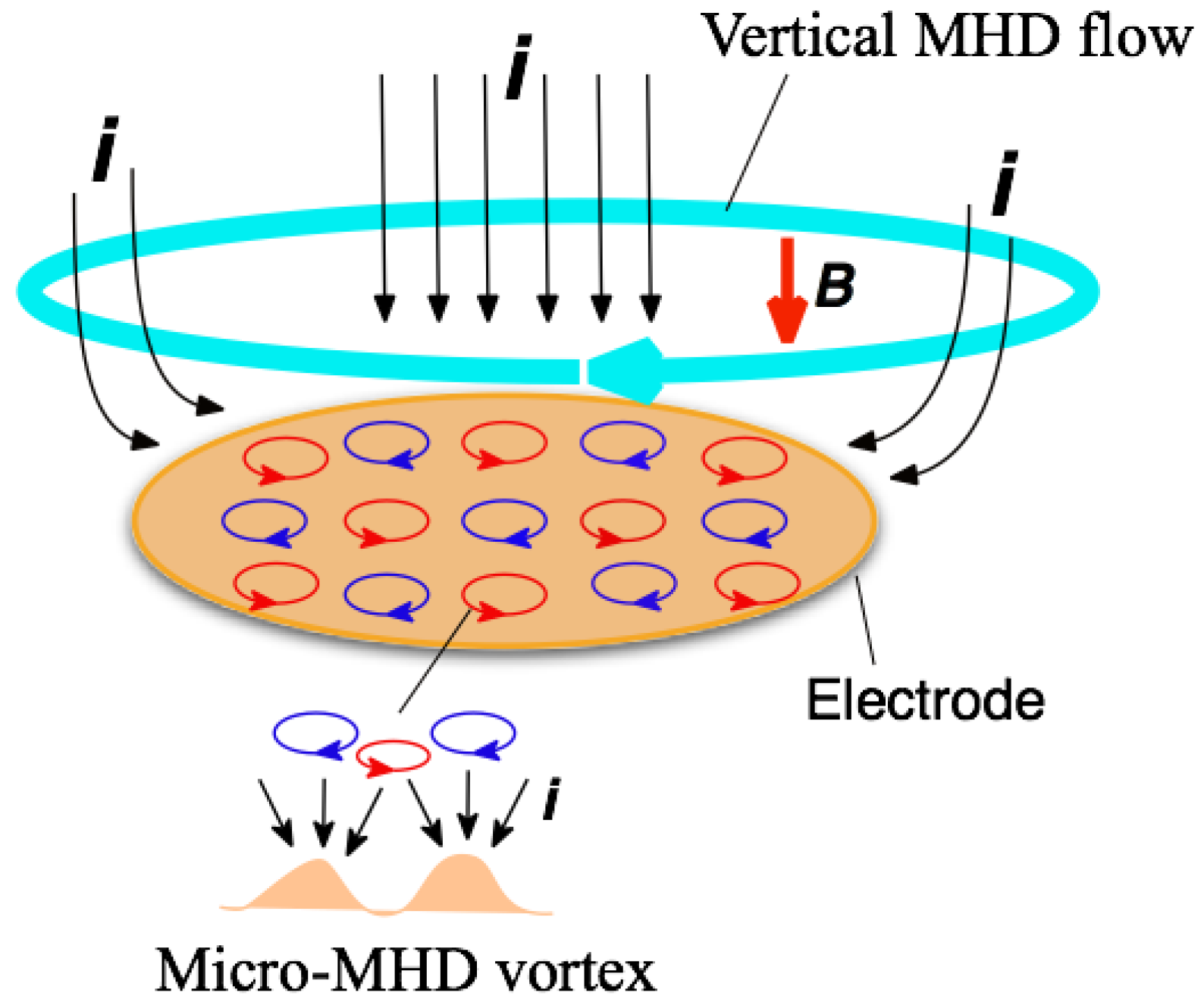
2.1. Effects of Tube Walls on Surface Chirality in MED

The potentiostatic MED of copper films were conducted in a CuSO4 + H2SO4 aqueous solution with the configuration of Figure 2a. The magnetic field of 5 T was imposed perpendicularly to a working electrode surface and parallel (+5 T) or antiparallel (−5 T) to the ionic currents. The working electrode was embedded in a Teflon® tube and the height (h) of tube wall was varied from 2 to 12 mm. In this configuration, the vertical MHD flow is excited around the entrance of tube, and then it penetrates into the inside of tube with damping, as shown in Figure 2b. Thus, the influence of vertical MHD flows on the film surfaces depends on the wall height.
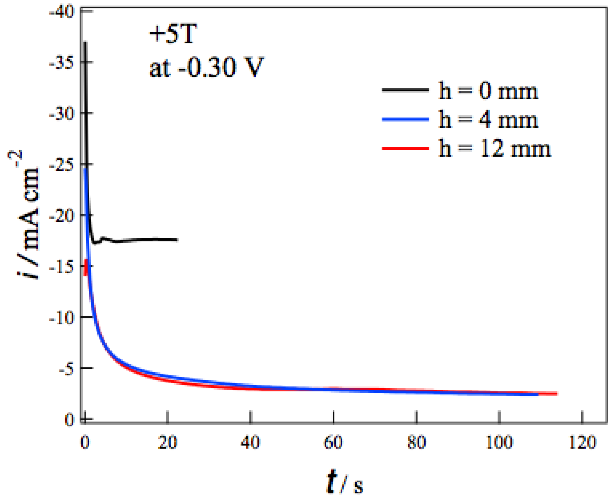
Figure 3 shows the current-time (i-t) curves during the MED at −0.3 V in +5 T without (h = 0 mm) and with the tube wall at h = 4 and 12 mm. In each i-t curve the deposition current decreases promptly at the initial 10 seconds and then reaches constant values. The self-organized state like Figure 1 would be formed in such a steady state [13]. Comparing i-t curves at different h, the tube walls drastically reduce the deposition currents. The tube walls suppress the vertical MHD flow effectively and result in the reduction of the mass-transfer to the electrode surface. It should be noted that the deposition currents at h = 4 mm are almost the same as those at h = 12 mm. This fact suggests that the penetrating vertical MHD flow does not reach the electrode surface even at h = 4 mm. Similar h dependence of i-t curves was observed at deposition potentials from −0.05 to −0.45 V.
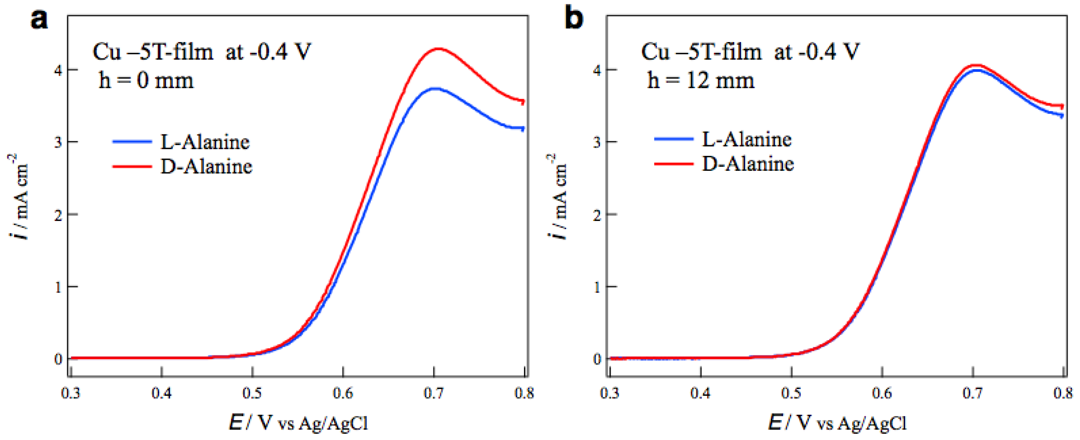
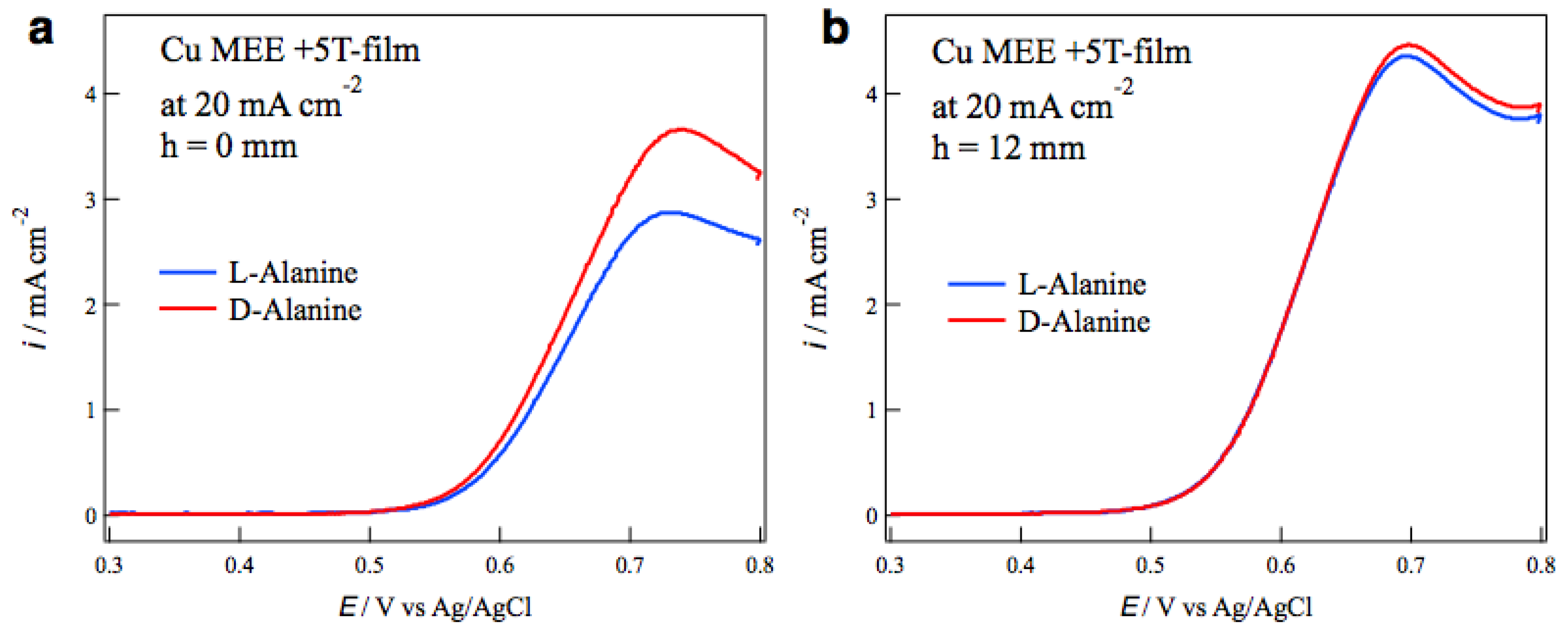
The surface chirality of MED films was examined by the measurements of voltammograms of alanine enantiomers on the MED film electrodes in a NaOH aqueous solution. The most typical result of tube wall effect on the surface chirality is seen in Figure 4. Figure 4a shows the voltammograms of L- and D-alanines on the MED −5T-films prepared at −0.4 V without tube wall. The peaks around 0.7 V correspond to the oxidation currents of alanine molecules [14], and the peak currents show chiral behavior for the enantiomers. The peak current of D-alanine is greater than that of L-alanine, namely this MED film exhibits D-active chirality. Figure 4b shows the voltammograms of alanine on the MED films prepared with tube wall at h = 12 mm in the same MED conditions as those in Figure 4a. The voltammograms are almost coincident between the enantiomers, namely this MED film has an achiral surface.
To evaluate the chirality in voltammograms, an enantiomeric excess (ee) ratio can be defined as
ee = (ipLipD)/(ipL + ipD)
where ipL and ipD represent the peak currents of L- and D-alanines, respectively. The positive sign of ee ratio represents L-activity, and the negative one represents D-activity. 
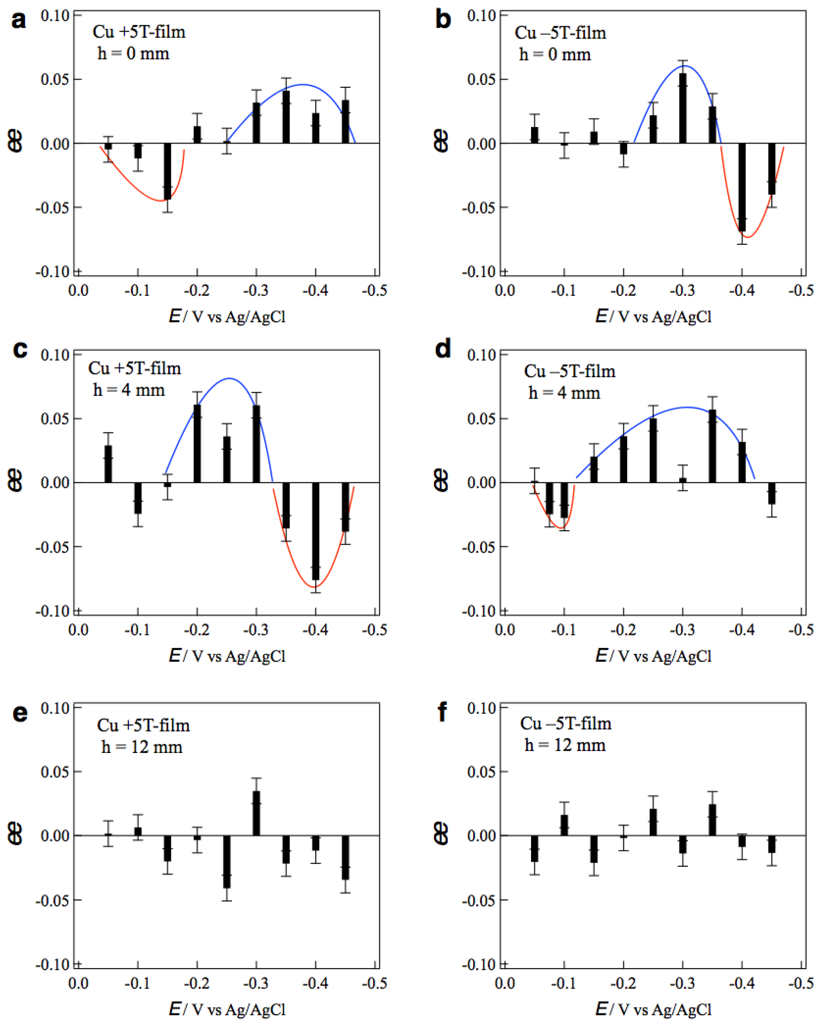
Figure 5a,b show the ee ratio profiles of the +5T-film and −5T-film electrodes, respectively, prepared without tube wall at various deposition potentials. The +5T-film exhibits D-activity in the potentials of 0.0~−0.15 V, and L-activity in the more negative potentials of −0.30~−0.45 V (Figure 5a). On the contrary, the −5T-film exhibits L-activity at −0.25~−0.35 V and D-activity at −0.40~−0.45 V. These results demonstrate that the chiral sign depends on both the deposition potential and the polarity of magnetic field.
The potential dependence of chirality implies that the rate-limiting step is responsible for the chiral sign. The voltammogram of Cu2+ at 5 T showed that the rate-limiting step changes around −0.3 V [15]. The electrode process is a kinetic-controlled at more positive potentials and mass-transfer-controlled at more negative potentials. Such a change in the rate-limiting step corresponds to the change in the chiral signs of MED films. In the mass-transfer-controlled process, the copper ions arriving at the film surface immediately react and deposit there. On the other hand, in the kinetic-controlled process, most copper ions arriving on the film surface cannot deposit instantaneously and diffuse on the surface. The micro-MHD effects on these copper ion behaviors could result in the change in chiral sign. Similar changes in the chiral signs were reported in the galvanostatic MED of Cu [15], where the chiral sign depended on the deposition currents and schematic explanation was described.
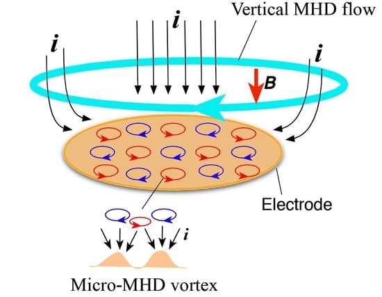
As for the magnetic-field-polarity dependence, the chiral sign is opposite for the reversal of the magnetic field. Such odd magnetic field dependence [16] can be simply understood by considering the direction of vertical MHD flow. As mentioned before, under the vertical MHD flow, the cyclonic micro-MHD vortices become stable, and the anticyclonic ones become unstable [10,11]. The reversal of magnetic field reverses the vertical MHD flow and the stable micro-MHD vortices, as a result, it changes the chiral signs of the MED films.
Figure 5c,d show the ee profiles of the +5T-film and −5T-film electrodes, respectively, prepared with tube wall at h = 4 mm. It is surprising that the ee profile of the +5T-film (Figure 5c) is almost the same as that of the −5T-film without wall (Figure 5b), and the profile of the −5T-film (Figure 5d) is the same as that of the +5T-film without wall (Figure 5a). These facts imply that the direction of vertical MHD flows around the electrode surface at h = 4 mm is opposite to that without wall. 
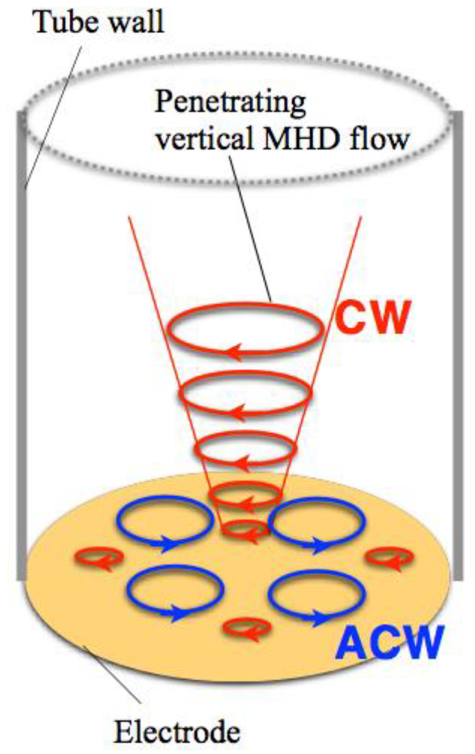
Figure 6 shows a possible scheme for such reversal of vertical MHD flow. The same deposition currents at h = 4 and 12 mm in Figure 3 suggest that the penetrating vertical MHD flow at h = 4 mm does not reach the electrode surface directly. However, when the front of penetrating flow would reach near the electrode surface, the reverse flows could be induced around the penetrating flow such that the adjoining flows never conflict with each other. If the penetrating flow is clockwise (CW), then the anti-clockwise (ACW) flows would be induced. Such induced flows could cause opposite chiral signs. This finding would be useful as a new simple method to control surface chirality.
The effects of tube wall were examined with taller walls. Figure 5e,f show the ee profiles of the +5T-film and −5T-film electrodes, respectively, prepared with the tube wall at h = 12 mm. No clear tendency in chiral signs is seen in both profiles, indicating that surface chirality almost disappeared on both MED films. The penetrating MHD flow could not reach the electrode surface and could not affect the micro-MHD vortices. These results demonstrate that the vertical MHD flow plays the significant role in the chiral surface formation; breaking of the symmetrical state in micro-MHD vortices.

2.2. Effects of Tube Walls on Surface Chirality in MEE

The self-organized MHD vortices like Figure 1 can be also formed in etching processes in magnetic fields, and the chiral surface formation was reported in the MEE processes [17]. The influence of tube wall on the surface chirality was examined in the MEE of copper films. The electrode configuration of MEE was the same as that in MED (Figure 2) except the ionic current direction. The MEE of copper films was conducted galvanostatically in a CuSO4 + H2SO4 aqueous solution in the magnetic fields of ±5 T. The most typical result of tube wall effect is seen in Figure 7. Figure 7a,b show the voltammograms of alanine enantiomers on the MEE +5T-film electrodes prepared without and with tube wall at h = 12 mm, respectively, at the etching current of 20 mA cm−2. While the MEE film without tube wall exhibits D-active behavior clearly, the MEE film with tube wall shows achiral behavior.
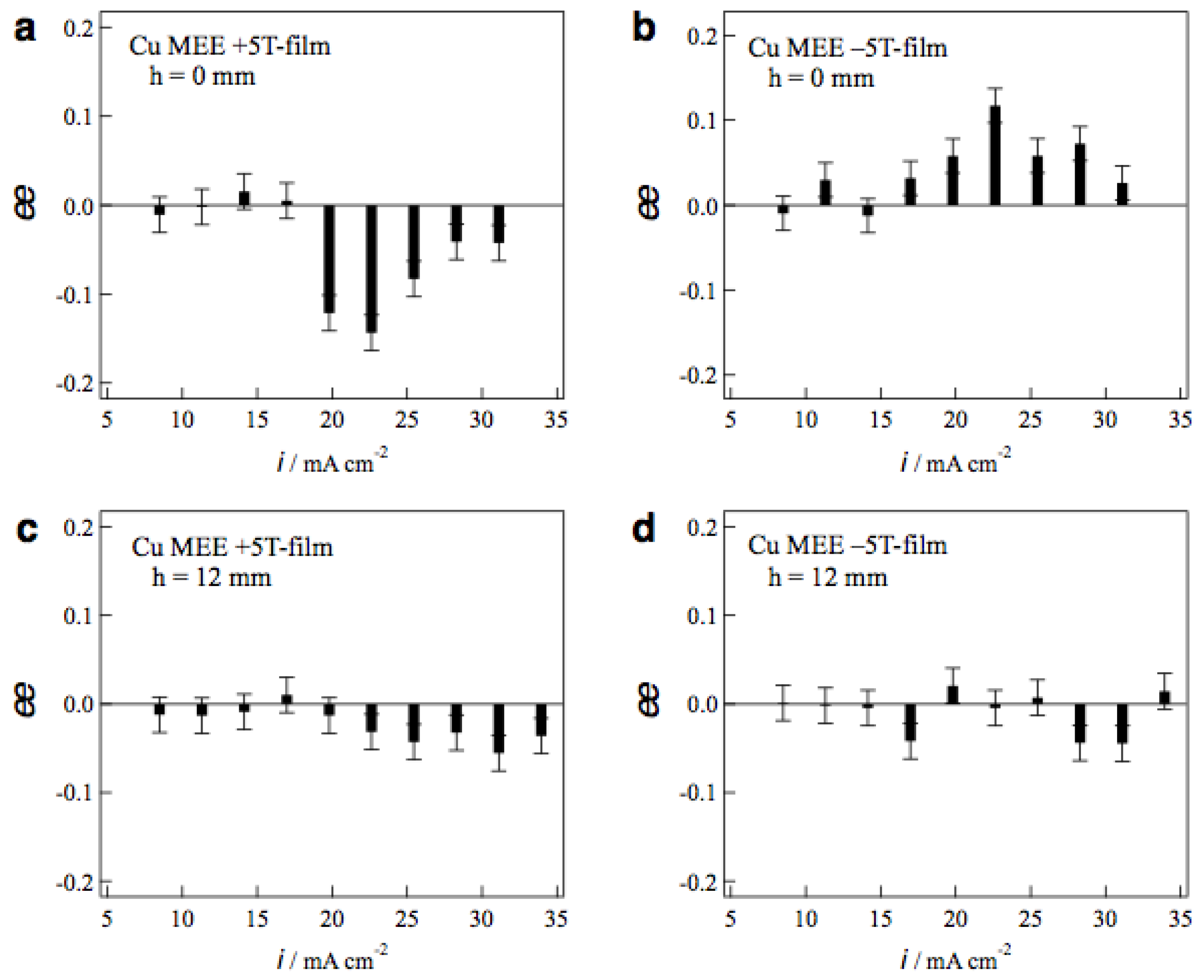
Figure 8a,b show the ee ratio profiles of MEE +5T-film and −5T-film electrodes, respectively, prepared without tube wall at various etching currents. The MEE +5T-film exhibits D-activity in the etching currents of 20−30 mA cm−2, and the −5T-film exhibits the L-activity in the same current region. The chiral signs of MEE films represent clear odd magnetic field dependence. Figure 8c,d shows the ee ratio profiles of MEE +5T-film and −5T-film electrodes, respectively, prepared with tube wall at h = 12 mm. The surface chirality almost disappears at whole etching currents on both films. This means that the penetrating vertical MHD flow does not reach the electrode surface at h = 12 mm and it cannot break the symmetrical self-organized state of micro-MHD vortices.
The large ee ratios (~0.2) were observed occasionally in the MEE experiments with tube wall at h = 2 and 4 mm, however, the reproducibility of such large values was poor. In these conditions, the penetrating vertical MHD flow could reach the electrode surfaces directly and make strong influence on the micro-MHD vortices. However, such strong influence never produces stable self-organized states, resulting in the lack of reproducibility.

3. Materials and Methods

3.1. Electrochemical Procedures

The electrochemical cell used in the MED and MEE experiments consists of a conventional three-electrode system (Figure 2a); a polycrystalline Pt disc working electrode (WE) with a diameter of 3 mm, a Cu plate counter electrode (CE), and an Ag|AgCl|3 M (M = mol dm−3) NaCl reference electrode (RE). In order to control the vertical MHD flow, the working electrode was embedded in a Teflon® tube, whose length was varied from 2 to 12 mm. The electrolytic solution was a 50 mM CuSO4 + 0.5 M H2SO4 aqueous solution. In the MED experiments, Cu films were electrodeposited up to a passing charge of 0.4 C cm−2 (the thickness of ~150 nm) on the working electrode at constant potentials from −0.05 to −0.45 V. In the presence of tube wall, the limiting currents of MED were almost constant at any electrode potential because the tube walls confined the mass-transfer in electrodeposition processes. The galvanostatic conditions with various deposition currents could not be carried out, thereby the potentiostatic conditions had to be employed in the MED experiments.
In the MEE experiments, before the etching process, Cu films were prepared with a thickness of approximately 300 nm on the working electrode by electrodeposition in the CuSO4 + H2SO4 aqueous solution in the absence of magnetic field. The electrochemical etching of Cu films was conducted in the same solution in galvanostatic conditions with various constant currents from 8.0 to 35 mA cm−2. The etching currents drastically change with slight potential changes, thereby the galvanostatic condition was employed in the MEE experiments. The passing charges were 0.80 C cm−2 in the film preparation process and 0.40 C cm−2 in the MEE process, and the MEE film thickness was approximately 150 nm.

3.2. MED and MEE Procedures

The electrochemical cell was placed in the bore of cryocooled superconducting magnet (Sumitomo Heavy Industries Ltd., Tokyo, Japan), and a magnetic field of 5 T was imposed perpendicularly to the working electrode surface, and parallel (+5 T) or antiparallel (−5 T) to the ionic currents. The experimental configuration of both MED and MEE was schematically described in Figure 2, where the ionic current direction was opposite in the case of MEE.

3.3. Estimation of Surface Chirality

To examine the chirality of MED and MEE films, the just-prepared films were employed as electrodes after the pretreatment of a potential sweep from −0.3 to 0.3 V in a 0.1 M NaOH aqueous solution [7], and the voltammogram of L- or D-alanine was measured on such a film electrode. The voltammetric measurements were conducted in a 20 mM L- or D-alanine + 0.1 M NaOH aqueous solution with a potential sweep rate of 10 mV s−1 in the absence of magnetic field. The ee values were estimated from several times experiments at each MED and MEE condition.

4. Conclusions

In the MED and MEE experiments with tube walls, we have demonstrated that the suppression of vertical MHD flows reaching the electrode surfaces diminishes the surface chirality. This result means that the self-organized state consisting of micro-MHD vortices and vertical MHD flow is indispensable for the chiral surface formation and that the vertical MHD flow plays a significant role in symmetry breaking of micro-MHD vortices. The MED and MEE with tube walls could be useful as a simple method for the control of surface chirality.

Author Contributions

I.M. and R.A. conceived and designed the experiments; I.M., R.M. and K.T. performed the experiments; K.T. contributed superconducting magnet tools; I.M. wrote the paper.

Funding

This research was funded by JSPS KAKENHI Grant-in-Aid for Scientific Research (C) No. 16K04913.

Acknowledgments

The authors thank the staff members of High Field Laboratory for Superconducting Materials of IMR Tohoku University for the use of the cryocooled superconducting magnet.

Conflicts of Interest

The authors declare no conflict of interest.

References

  1. Fahidy, T.Z. Magnetoelectrolysis. J. Appl. Electrochem. 1983, 13, 553–563. [Google Scholar] [CrossRef]
  2. Monzon, L.M.A.; Coey, L.M.D. Magnetic Fields in Electrochemistry: The Lorentz Force. Electrochem. Commun. 2014, 42, 38–41. [Google Scholar] [CrossRef]
  3. Aogaki, R. Micro-MHD Effect on Electrodeposition in Vertical Magnetic Field. Magnetohydrodynamics 2003, 4, 453–460. [Google Scholar]
  4. Mogi, I.; Morimoto, R.; Aogaki, R. Surface Chirality Effects Induced by Magnetic Fields. Curr. Opin. Electrochem. 2018, 7, 1–6. [Google Scholar] [CrossRef]
  5. Mogi, I.; Watanabe, K. Chiral Electrode Behavior of Magneto-Electrodeposited Silver Films. ISIJ Int. 2007, 47, 585–587. [Google Scholar] [CrossRef]
  6. Mogi, I.; Watanabe, K. Enantioselective Recognition of Tartaric Acid on Magnetoelectrodeposited Copper Film Electrodes. Chem. Lett. 2012, 41, 1439–1441. [Google Scholar] [CrossRef]
  7. Mogi, I.; Watanabe, K. Chiral Recognition of Amino Acids by Magnetoelectrodeposited Cu Film Electrodes. Int. J. Electrochem. 2011. [Google Scholar] [CrossRef]
  8. Mogi, I.; Iwasaka, K.; Aogaki, R.; Takahashi, K. Visualization of Magnetohydrodynamic Micro-Vortices with Guanine Micro-Cryastals. J. Electrochem. Soc. 2017, 164, H584–H586. [Google Scholar] [CrossRef]
  9. Yanson, Y.I.; Rost, M.J. Structural Accelerating Effect of Chloride on Copper Electrodeposition. Angew. Chem. Int. Ed. 2013, 52, 2454–2458. [Google Scholar] [CrossRef] [PubMed]
  10. Sommeria, J.; Meyers, S.D.; Swinney, H.L. Laboratory Simulation of Jupiter’s Great Red Spot. Nature 1988, 331, 689–693. [Google Scholar] [CrossRef]
  11. Marcus, S.M. Numerical Simulation of Jupiter’s Great Red Spot. Nature 1988, 331, 693–696. [Google Scholar] [CrossRef]
  12. Aogaki, R.; Morimoto, R. Nonequilibrium Fluctuations in Micro-MHD Effects on Electrodeposition. In Heat and Mass Transfer: Modeling and Simulation; Hossain, M., Ed.; InTech: Rijeka, Croatia, 2011; pp. 189–216. ISBN 9789533076041. [Google Scholar]
  13. Mogi, I.; Aogaki, R.; Morimoto, R.; Watanabe, K. Magnetoelectrodeposition for the Chiral Surface Formation of Cu Films. ECS Trans. 2013, 45, 1–8. [Google Scholar] [CrossRef]
  14. Luo, P.; Zhang, F.; Baldwin, R.P. Constant Potential Amperometric Detection of Underivatized Amino Acids and Peptides at A Copper Electrode. Anal. Chem. 1991, 63, 1702–1707. [Google Scholar] [CrossRef]
  15. Mogi, I.; Aogaki, R.; Watanabe, K. Tailoring of Surface Chirality by Micro-Vortices and Specific Adsorption in Magnetoelectrodeposition. Bull. Chem. Soc. Jpn. 2015, 88, 1479–1485. [Google Scholar] [CrossRef] [Green Version]
  16. Rikken, G.L.J.A.; Folling, J.; Wyder, P. Electrical Magnetochiral Anisotropy. Phys. Rev. Lett. 2001, 87, 236602. [Google Scholar] [CrossRef] [PubMed]
  17. Mogi, I.; Aogaki, R.; Watanabe, K. Chiral Surface Formation of Copper Films by Magnetoelectrochemical Etching. Magnetohydrodynamics 2015, 51, 361–368. [Google Scholar]
Figure 1. Schematic of the vertical magnetohydrodynamic (MHD) flow and the micro-MHD vortices around a working electrode in the magnetoelectrodeposition (MED) experiments with the configuration of magnetic field B parallel to ionic currents i.
Magnetochemistry 04 00040 g001
Figure 2. (a) Configuration of the electrochemical cell and a superconducting magnet in the MED experiments. WE; a working electrode, CE; a counter electrode and RE; a reference electrode. (b) Penetration of the vertical MHD flow into a tube around a working electrode.
Magnetochemistry 04 00040 g002
Figure 3. Current-time curves during the MED of copper films at −0.3 V in +5 T without (h = 0 mm) and with tube wall at h = 4 and 12 mm.
Magnetochemistry 04 00040 g003
Figure 4. Voltammograms of alanine enantiomers on the MED −5T-film electrodes prepared at −0.4 V (a) without tube wall and (b) with tube wall at h = 12 mm.
Magnetochemistry 04 00040 g004
Figure 5. Profiles of the ee ratios of the MED 5T-film electrodes vs. the deposition potentials. The MED films were prepared in the conditions of (a) h = 0 mm, +5 T, (b) h = 0 mm, −5 T, (c) h = 4 mm, +5 T, (d) h = 4 mm, −5 T, (e) h = 12 mm, +5 T and (f) h = 12 mm, −5 T. Blue and red curves are a guide for eyes.
Magnetochemistry 04 00040 g005
Figure 6. Schematic of the reversal of vertical MHD flows near the electrode surface in a tube wall.
Magnetochemistry 04 00040 g006
Figure 7. Voltammograms of alanine enantiomers on the magnetoelectrochemical etching (MEE) +5T-film electrodes prepared at 20 mA cm−2 (a) without tube wall and (b) with tube wall at h = 12 mm.
Magnetochemistry 04 00040 g007
Figure 8. Profiles of the ee ratios of the MEE 5T-film electrodes vs. the etching currents. The MEE films were prepared in the conditions of (a) h = 0 mm, +5 T, (b) h = 0 mm, −5 T, (c) h = 12 mm, +5 T and (d) h = 12 mm, −5 T.
Magnetochemistry 04 00040 g008

