Article

Tuning the Structure and Properties of Lanthanoid Coordination Polymers with an Asymmetric Anilato Ligand

by
Patricia Gómez-Claramunt
1,
Samia Benmansour
1,*,
Antonio Hernández-Paredes
1,
Christian Cerezo-Navarrete
1,
Carlos Rodríguez-Fernández
1,
Josep Canet-Ferrer
1,2,
Andrés Cantarero
1 and
Carlos J. Gómez-García
1,*
1
Instituto de Ciencia Molecular (ICMol), Departamento de Química Inorgánica, Universidad de Valencia, C/ Catedrático José Beltrán 2, 46980 Paterna, Spain
2
ICFO-Institut de Ciencies Fotoniques, Barcelona Institute of Science and Technology, 08860 Castelldefels, Spain
*
Authors to whom correspondence should be addressed.
Magnetochemistry 2018, 4(1), 6; https://doi.org/10.3390/magnetochemistry4010006
Submission received: 6 December 2017 / Revised: 21 December 2017 / Accepted: 26 December 2017 / Published: 2 January 2018

Abstract

:
Five new anilato-based, Ln(III)-containing, layered compounds have been prepared with the asymmetric ligand chlorocyananilato (C6O4(CN)Cl)2−; different Ln(III) ions Ce(III), Pr(III), Yb(III), and Dy(III); and the three different solvents H2O, dimethylsolfoxide (DMSO), and dimethylformamide (DMF). Compounds [Ce2(C6O4(CN)Cl)3(DMF)6]·2H2O (1), [Pr2(C6O4(CN)Cl)3(DMF)6] (2), [Pr2(C6O4(CN)Cl)3(DMSO)6] (3), [Yb2(C6O4(CN)Cl)3(DMSO)4]·2H2O (4) and [H3O][Dy(C6O4(CN)Cl)2(H2O)]·4H2O (5) show the important role that the Ln(III) size, as well as the size and shape of the solvent may play in the crystal structure of each compound. Compounds 14 present (6,3)-2D hexagonal lattices, with important differences in the coordination number and geometry of the Ln(III) ion, as well as in the distortion of the hexagonal cavities, depending on the Ln(III) and solvent size. Compound 5 (the only one prepared with water) presents a (4,4)-2D square lattice, where the Dy(III) ions are surrounded by four chelating anilato ligands. Compounds 24 are essentially paramagnetic, confirming the presence of weak (if any) magnetic coupling mediated by the anilato ligands when connecting Ln(III) ions. Compounds 24 showed a red shift and a broadening of the emission band of the ligand. Compound 4 also showed a strong emission band attributed to the Yb(III), suggesting an antenna effect of the ligand. An energy transfer diagram is proposed to explain these luminescent properties.

Graphical Abstract

1. Introduction

The design of crystalline porous coordination polymers, or metal organic frameworks (MOFs) with different cavities sizes and shapes, is one of the hottest topics in Coordination Chemistry [1,2]. The modulation and control of the shape and size of the cavities is a key aspect to designing MOFs with tailored properties, for applications in gas storage and separation [3,4], water adsorption [5], energy storage [6,7], catalysis [8,9], sensors [10,11], biomedicine [12,13], or for combining several properties in the same MOF [14].
In most MOFs, the building blocks used are transition (and group 12) metal atoms or complexes linked by different types of ligands (mainly organic). In recent years, lanthanides have become very popular for preparing MOFs with luminescence properties that can be used as sensors [15,16,17].
Among the different ligands used to construct MOFs, polycarboxylic acids (including aromatic) are the most common, given their high coordination capacity and different coordination modes [14,18,19,20,21]. Other ligands include aromatic amines and quinones, such as the 2,5-dihydroxy-1,4-benzoquinone dianion (C6O4H2)2− = dhbq, and the corresponding 3,6-disubstituted dianions (C6O4X2)2−, with X = Cl, Br, NO2, CN, ... (Figure 1) [22,23]. These derivatives of 2,5-dihydroxy-1,4-benzoquinone (anilato-type ligands) are becoming popular ligands, since they resemble the oxalato ligand (Figure 1), although with some advantages. Their larger size gives rise to larger cavities and channels, and gives the possibility to change the X group (Figure 1). The similarities of oxalato and anilato-type ligands can be clearly seen in the classical chiral [M(L)3]3− monomers [24,25], as well as in the extended 2D and 3D lattices observed for both ligands [22,26,27,28,29,30].
Although anilato-type ligands have been mainly used with transition metal ions [22,23], there are also several examples of anilato-based compounds with lanthanoids (Table 1, Table 2, Table 3 and Table 4). These compounds can be formulated as [Ln2(C6O4X2)3(G)n]·mG, and can be grouped into different series depending on X (the anilato-type ligand) and G (the solvent used).
Thus, for X = H (i.e., with the ligand C6O4H22− = dhbq2−) and G = H2O (Table 1), all the Ln(III) ions form isostructural compounds (phase I) formulated as [Ln2(C6O4H2)3(H2O)6]·18H2O, whose structure consists in a (6,3)-2D honeycomb lattice formed by regular (although not planar) hexagons, and where the Ln(III) ions are nona-coordinated with a tri-capped trigonal prismatic geometry [31,32,33].
When X = Cl (i.e., with the ligand C6O4Cl22− = chloranilato) and G = H2O (Table 2), up to four different phases, formulated as [Ln2(C6O4Cl2)3(H2O)6]·nH2O, could be prepared, depending exclusively on the size of the Ln(III) ion. Phase I, with n = 14, is observed for the larger Ln(III) ions (La, Ce, Pr and Nd). Phase II, with n = 12, is formed by the intermediate lantanoids (Sm, Eu, Gd, Tb, Dy and Ho). Phase III, with n = 10, is only observed for Ln = Er(III). Finally, phase IV, with n = 8, is formed by the smallest lanthanoids (Tm and Yb) [31,32,33]. These four phases show all the same (6,3)-2D topology, but differ in the distortions of the hexagonal cavities and in the orientation of the chloranilato ligands, with respect to the average plane of the cavity that can be “edge-on” (E) or “face-on” (F) when the anilato plane is perpendicular or parallel to the cavity plane, respectively. In phases I and II, there are four “edge-on” and two “face-on” chloranilato ligands (4E-2F, or type a) [31], whereas in phase III the ligands present the orientation 2E-4F, or type b [31]. Phase IV also shows a 4E-2F orientation of the chloranilato ligands, but the cavities are so distorted that they are rectangular. This type of rectangular cavity (called type c by Robson) [31] had only been observed in [Y2(C6O4X2)3(H2O)6]·6H2O (X = Cl and Br) [34], [Pr2(C6O4Cl2)3(EtOH)6]·2EtOH [35] and [Er2(C6O4Br2)3(DMF)6] [36].
For X = Br (i.e., with the ligand C6O4Br22− = bromanilato) and G = H2O (Table 3), only two different phases, formulated as [Ln2(C6O4Br2)3(H2O)6]·nH2O, have been obtained: phase I, with n = 12, was obtained for the larger Ln(III) ions (La to Er); whereas phase II, with n = 8, was obtained for the two smallest ones (Yb and Tm) [33]. Phase I shows a (4E, 2F) disposition (type a) and phase II shows rectangular cavities also with a (4E, 2F) disposition (type c).
The last anilato-type ligand that has been combined with lanthanoids and water is nitranilato (X = NO2). In this ligand, the two NO2 groups are tilted with respect to the anilato plane, giving rise to a large steric effect that precludes the formation of the (6,3)-lattices observed when X = H, Cl and Br. Thus, for nitranilato, all the attempts to obtain the 2D lattice led to a series of nitranilato-bridged dimers, formulated as [Ln2(C6O4(NO2)2)3(H2O)10]·6H2O (Ln(III) = Sm, Eu, Gd, Tb, Dy, Ho and Er) (Table 4) [33,37]. The Ho(III) derivative of this series shows luminescence, due to the nitroanilato ligand, being superimposed with a weaker emission from the lanthanide ion [37]. Attempts to combine larger or smaller Ln(III) ions with nitranilato have been unsuccessful to date.
Besides water, other solvents, such as ethanol (EtOH), dimethylsolfoxide (DMSO), and dimethylformamide (DMF), have been used to prepare these Ln(III)-compounds with anilato-type ligands. Interestingly, the ability of these solvents to coordinate the Ln(III) ions, has led to different phases and structures where the solvents are coordinated to the Ln(III) ions, replacing the three coordinated water molecules present in all the aqueous phases presented in Table 1, Table 2 and Table 3.
The very few examples reported, to date, with solvents other than water include [Pr2(C6O4Cl2)3(EtOH)6]·2EtOH [35], [Er2(C6O4Br2)3(DMSO)4]·2DMSO·2H2O [36], [Er2(C6O4Br2)3(DMF)6] [36], and the very recently reported series formulated as [Ln2(C6O4Br2)3(DMSO)n]·2DMSO·mH2O, with n = 6 and m = 0 when Ln = La-Gd, and n = 4 and m = 2 when Ln = Tb-Yb [38]. These three compounds present the same (6,3)-2D topology, but the cavities are rectangular (in the EtOH and DMF cases) or have a very distorted hexagonal shape (in the DMSO compound), suggesting that the solvent plays an important role in the final structure. Thus, the change of water in compound [Er2(C6O4Br2)3(H2O)6]·12H2O to other coordinating solvents, such as DMSO, and DMF, leads to changes in the coordination number and geometry of the metal (nine for H2O and DMF vs. eight for DMSO), in the size and distortions of the cavities (hexagonal for H2O, distorted hexagonal for DMSO, and rectangular for DMF), in the content of the cavities (12 H2O molecules, two DMSO and two H2O molecules, or nothing), and even in the interlayer separation [36].
Very recently, Mercuri et al. [39] reported the series of complexes A3[MIII(C6O4(CN)Cl)3], with A = NBu4+ and PPh4+ and MIII = Fe, Cr, and Al. Although these monomeric complexes contain d- and p-block metals, they also contain the asymmetric 2-chloro-5-cyano-3,6-dihydroxybenzoquinone (chlorocyananilato) ligand (C6O4(CN)Cl2−) [40]. Interestingly, this ligand shows luminescent properties in solid state [40] and in solution [39], as well as in the two Al(III) complexes.
Given these above-mentioned results: (i) the luminescence of the nitranilato derivative with Ho(III) [37], (ii) the intrinsic luminescence of the chlorocyananilato ligand [39,40], (iii) the luminescence shown by many Ln(III) ions, (iv) the above-mentioned ability of anilato ligands to form 2D lattices with all the Ln(III) ions [31,33,36] (Table 1, Table 2 and Table 3), and (v) the capacity shown by some coordinating solvents to modify these 2D lattices [35,36], we have initiated a detailed study to prepare and characterize the complete series of compounds with Ln(III) ions and the ligand chlorocyananilato. Furthermore, we have decided to use different solvents as H2O, DMF, and DMSO, since these solvents have a high ability to coordinate to the Ln(III) ions [41], and are therefore expected to modulate not only the luminescent properties, but also the structure of the resulting compounds, as has been very recently demonstrated by some of us [36]. Here, we present the first results obtained by combining the chlorocyananilato ligand, (C6O4(CN)Cl)2− with different Ln(III) ions as Ce(III), Pr(III), Dy(III), and Yb(III), as well as with different solvents as H2O, DMF, and DMSO. Thus, we have synthesized and characterized five compounds, formulated as [Ce2(C6O4(CN)Cl)3(DMF)6]·2H2O (1), [Pr2(C6O4(CN)Cl)3(DMF)6] (2), [Pr2(C6O4(CN)Cl)3(DMSO)6] (3), [Yb2(C6O4(CN)Cl)3(DMSO)4]·2H2O (4) and [H3O][Dy(C6O4(CN)Cl)2(H2O)]·4H2O (5). These five compounds represent the first obtained using Ln(III) and the chlorocyananilato ligand. Further work to complete the series with all the Ln(III) ions and all the solvents is underway.

2. Results and Discussion

2.1. Syntheses of the Complexes

These five compounds were synthesized by carefully layering solutions containing the Ln(III) ion, dissolved in methanol (for 14) or in H2O (for 5) and the asymmetric chlorocyananilato ligand (as its monopotassium, dipotassium, or tetraphenylphosphonium salts), dissolved in the corresponding solvent: DMF (for 1 and 2), DMSO (for 3 and 4) or H2O (for 5). As expected, given the great ability of these solvents to coordinate Ln(III) ions [41], the solvents appear coordinated to the Ln(III) ion in the final compounds. The slow diffusion of the reagents allowed the synthesis of good quality single crystals for the determination of the X-ray structure in all cases.

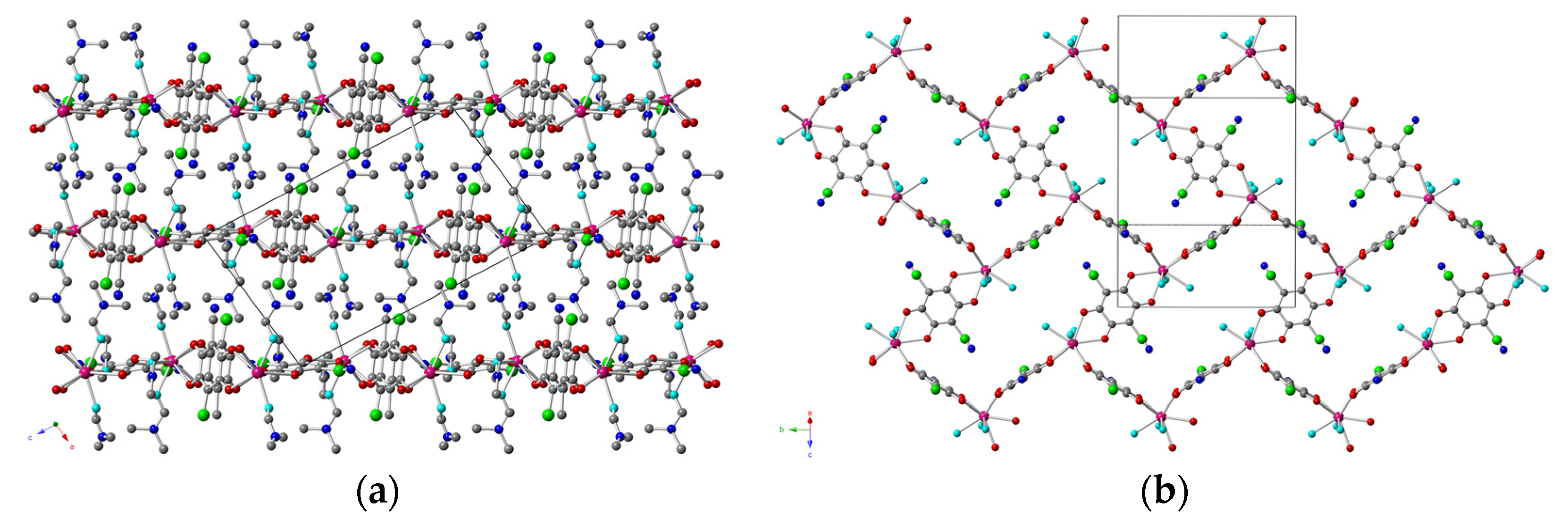
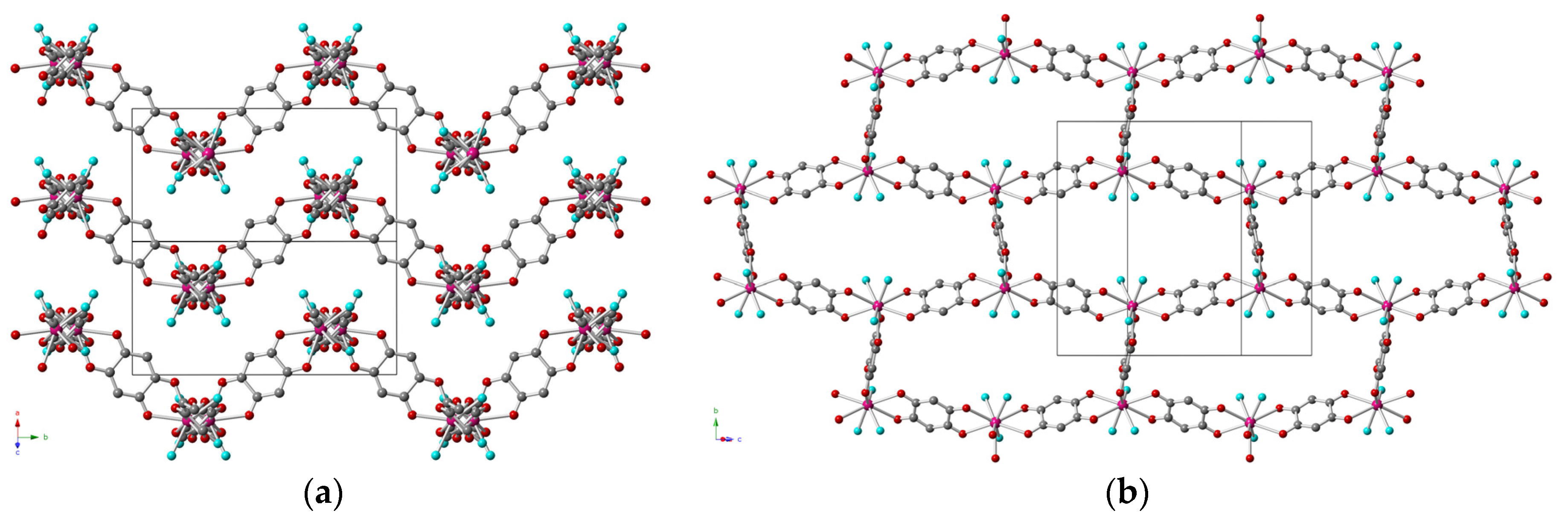
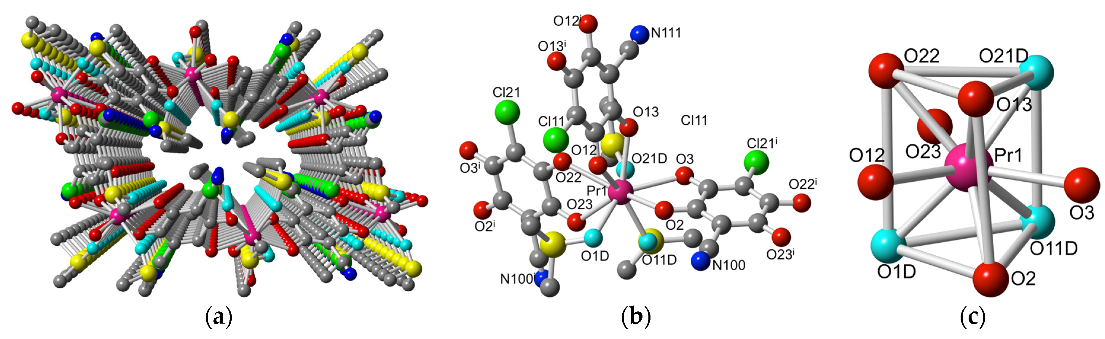
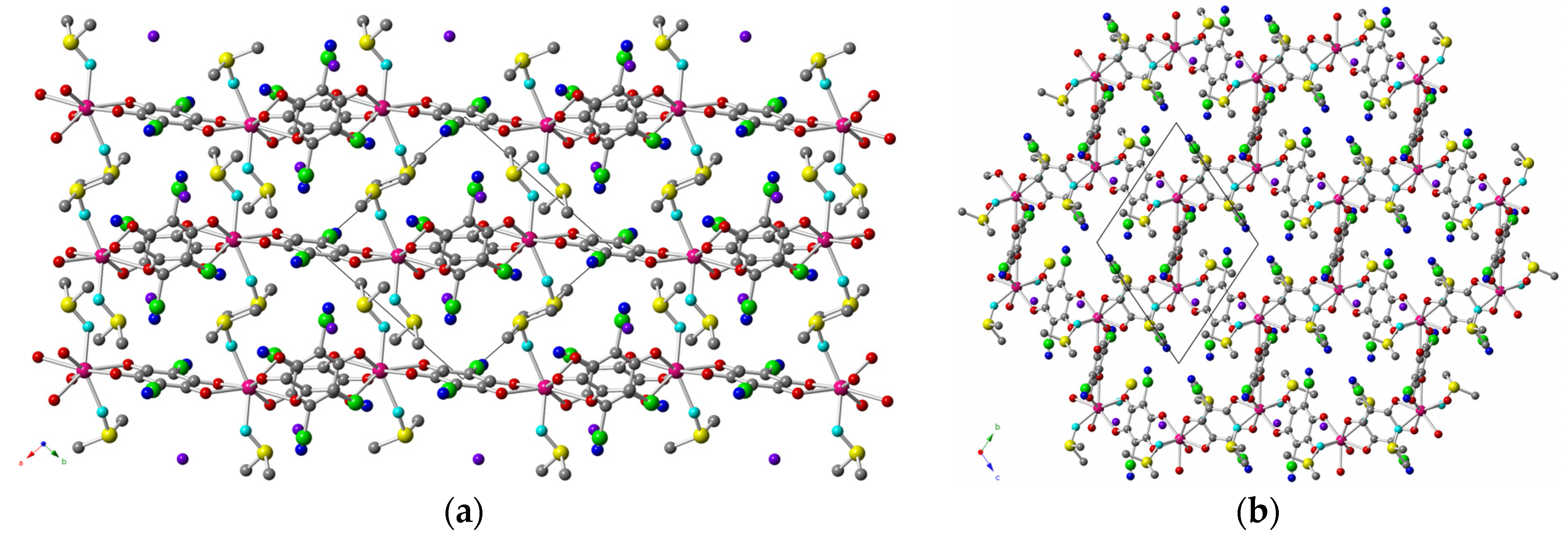
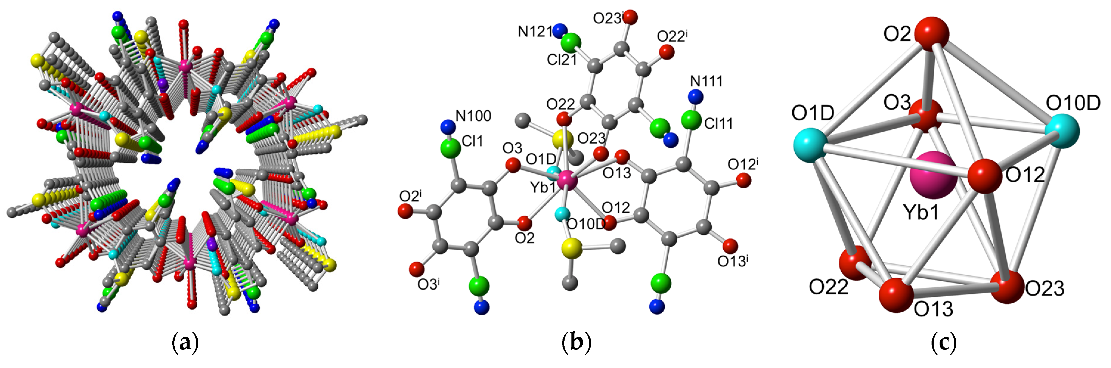
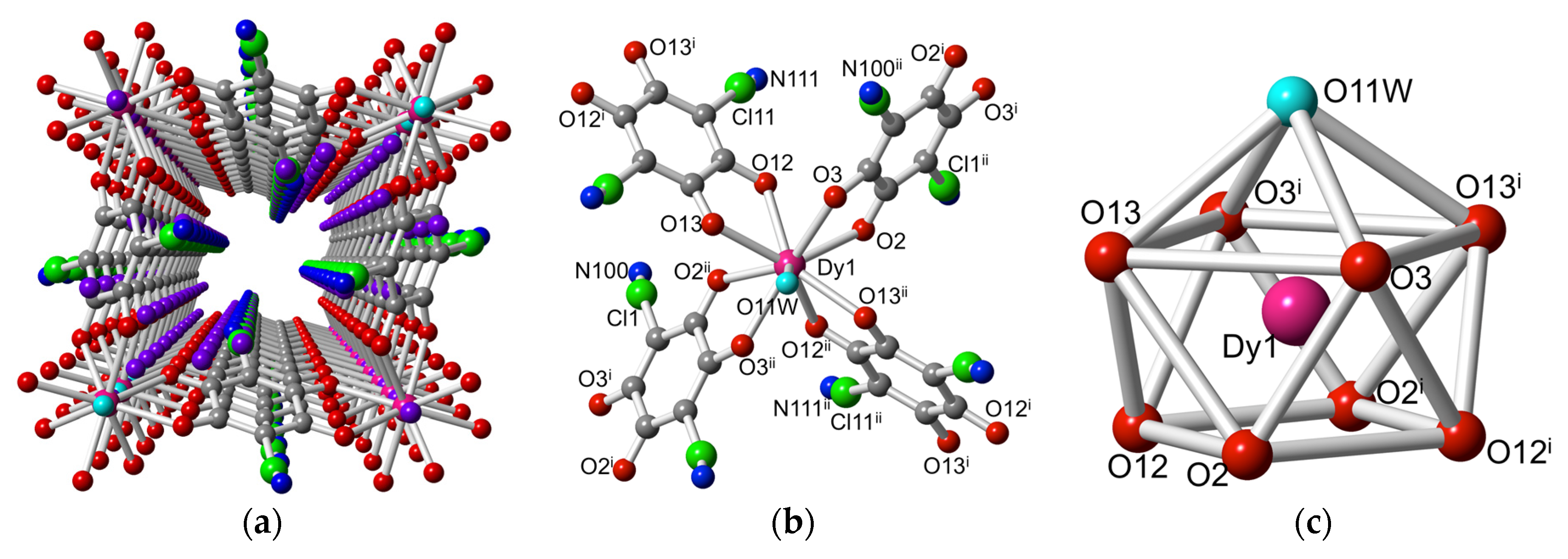
2.2. Description of the Structures

Structure of [Ce2(C6O4(CN)Cl)3(DMF)6]·2H2O (1). Compound 1 crystallizes in the monoclinic C2/c space group (Table 5). The asymmetric unit contains one Ce(III) ion, three-halves chlorocyananilato ligands, three coordinated DMF molecules, and two crystallization water molecules with occupancy factor of one-half, giving rise to the general formula [Ce2(C6O4(CN)Cl)3(DMF)6]·2H2O. The presence of an inversion centre in the centre of the three anilato rings generated a disorder between the Cl and CN groups of the ligands, which appeared disordered with one-half occupancies each.
The structure of compound 1 consists of corrugated hexagonal layers parallel to the ab plane (Figure 2a), with a honeycomb (6,3)-topology (Figure 2b), where each Ce(III) ion is connected to three other Ce(III) ions through anilato ligands, forming six-membered rings. The layers are packed in an eclipsed way, giving rise to hexagonal channels along the [101] direction (Figure 3a). The hexagonal cavities of these layers show a chair conformation, and are almost regular, as shown by the three similar diagonal Ce-Ce distances (16.11, 16.48 and 16.52 Å). The crystallization water molecules and the coordinated DMF molecules occupy the inter-laminar space in the cavities formed by the zigzag layers (Figure 2a).
The Ce(III) ion is surrounded by three chelating anilato ligands and three oxygen atoms of three DMF molecules (Figure 3b), with the coordination geometry of a distorted tri-capped trigonal prism (Figure 3c). The DMF molecules occupy one of the triangular faces of the trigonal prism, whereas the three chelating anilato ligands connect one position of the other triangular face with one equatorial position (Figure 3c). This particular disposition of the coordinated DMF molecules and anilato ligands is identical to that found in the series of compounds [Ln2(dhbq)3(H2O)6]·18H2O prepared with dhbq2− (X = H) and Ln(III) ions (Table 1), which also generated a honeycomb (6,3) structure with very similar regular and nonplanar hexagonal cavities.
Structure of [Pr2(C6O4(CN)Cl)3(DMF)6] (2). Compound 2 crystallizes in the monoclinic P21/n space group (Table 5). The asymmetric unit contains one Pr(III) ion, one-and-a-half chlorocyananilato ligands, and three coordinated DMF molecules, giving rise to the general formula [Pr2(C6O4(CN)Cl)3(DMF)6]. One anilato ligand has an inversion centre in the centre of the anilato ring, generating a disorder between the Cl and CN groups. The other anilato ligand did not contain any symmetry element, but it also showed a positional disorder of the Cl and CN group.
The structure of compound 2 also shows layers (Figure 4a) with a (6,3) topology, where each Pr(III) ion is connected to three other Pr(III) ions through anilato ligands, forming six-membered rings. The difference between compounds 1 and 2 is that in compound 2, the layers are almost planar, and the six-membered rings are so distorted that they appear as rectangles (Figure 4b). These rectangles are disposed in rows along the b direction, in such a way that the rectangles of consecutive rows are orthogonal, giving rise to a spike-like layer (Figure 4b). These layers are packed in an eclipsed way, generating rectangular channels along the a direction (Figure 5a).
The Pr(III) ion is surrounded by three chelating anilato ligands and three oxygen atoms of three DMF molecules (Figure 5b), with a coordination geometry of a slightly distorted, mono-capped square antiprism (Figure 5c). The DMF molecules occupy three positions of the capped square. One chelating anilato ligand occupies the remaining position in this square face and the capping position, while the two other anilato ligands occupy consecutive positions in the basal square. (Figure 5c). This particular disposition of the coordinated DMF molecules and the anilato ligands in the coordination polyhedron is responsible for the spatial orientation of the anilato bridges, and, therefore, for the shape of the rectangular cavity, and for the 4E-2F disposition shown by the bridges (Figure 4b).
If we compare the structures of compounds 1 and 2, we can see that the only difference between both compounds is the Ce(III) ion in compound 1 and the Pr(III) ion in compound 2. Even if both ions are similar in size, we can see that a small change in the size of the Ln(III) ion plays a key role in determining the shape and size of the cavities in the (6,3)-2D lattices in the compounds’ structures. Thus, in compound 1, the larger Ce(III) ion gives rise to a distorted tri-capped trigonal prismatic geometry, where the three coordinated DMF molecules are located in one of the triangular faces, leading to corrugated hexagonal layers with regular hexagonal cavities with a chair conformation. In contrast, the slightly smaller size of Pr(III) in compound 2 gives rise to a distorted mono-capped square antiprism that leads to a different spatial orientation of the DMF molecules and the anilato bridges and, accordingly, to a different cavity shape (rectangular instead of hexagonal, Figure 2b and Figure 4b), with a 4E-2F orientation of the anilato bridges in the cavities of compound 2.
Structure of [Pr2(C6O4(CN)Cl)3(DMSO)6] (3). Compound 3 crystallizes in the monoclinic P21/n space group (Table 5). The asymmetric unit contains one Pr(III) ion, one-and-a-half chlorocyananilato ligands, and three coordinated DMSO molecules, giving rise to the general formula [Pr2(C6O4(CN)Cl)3(DMSO)6]. As observed in compound 2, one anilato ligand has an inversion centre in the centre of the anilato ring, generating a disorder between the Cl and CN groups. The other anilato ligand does not contain any symmetry element, but it also shows a positional disorder of the Cl and CN group.
The structure of compound 3 shows corrugated layers (Figure 6a), with a (6,3) topology similar to those observed in compound 1, where each Pr(III) ion is connected to three other Pr(III) ions through anilato ligands, forming six-membered rings. The two main differences between compound 3 and compound 1 are: (i) in compound 3, the hexagonal rings are very distorted (Figure 6b), as shown by the three very different Pr-Pr diagonal distances (11.03, 19.34 and 20.58 Å); and (ii) the oscillation of two consecutive layers in compound 3 is parallel (valley to valley and peak to peak), precluding the formation of square interlayer cavities. In compound 1, consecutive layers oscillate in opposite phases (valley to peak and peak to valley, Figure 2a). The layers are also packed in an eclipsed way, generating very distorted hexagonal channels along the a direction (Figure 7a).
The Pr(III) ion is surrounded by three chelating anilato ligands and three oxygen atoms of three DMSO molecules (Figure 7b), with a coordination geometry of a distorted tri-capped trigonal prism (Figure 7c). The DMSO molecules occupy two positions of one triangular face and one position of another face, whereas the three anilato ligands connect a triangular position with an equatorial one (Figure 7c). This particular disposition of the coordinated DMSO molecules and the anilato ligands is responsible for the spatial orientation of the anilato bridges, and for the large distortion of the hexagonal cavity, which shows a 2E-4F disposition of the bridging anilato ligands (Figure 6b).
Compounds 2 and 3 have the same Pr(III) ion and chlorocyananilato ligand and only differ in the solvent molecule used (DMF in compound 2 and DMSO in compound 3). Although the coordination number is the same, the change from DMF to DMSO produces a change in the coordination geometry (from distorted mono-capped square antiprism in compound 2 to distorted tri-capped triangular prism in compound 3). This change has to be attributed to the larger steric effect produced by DMSO compared to that produced by DMF. In the DMSO molecule, the two bulky methyl groups are closer to the coordinating O atom than in DMF, since in DMSO the groups are separated by only a S atom, whereas in DMF they are separated by a two-atoms chain (-C-N-). This shorter distance in DMSO generates a larger solid angle, and therefore, a larger steric effect. The change in the coordination geometry gives rise to a different orientation of the bridging anilato ligand, and, accordingly, to a different distortion of the cavities, and a different distortion of the orientation of these cavities in the (6,3)-lattice: spike-like in compound 2 and brick-wall-like in compound 3 (Figure 4b and Figure 6b).
Structure of [Yb2(C6O4(CN)Cl)3(DMSO)4]·2H2O (4). Compound 4 crystallizes in the triclinic P-1 space group (Table 5). The asymmetric unit contains one Yb(III) ion, three-halves chlorocyananilato ligands, two coordinated DMSO molecules and one crystallization water molecule, giving rise to the general formula [Yb2(C6O4(CN)Cl)3(DMSO)4]·2H2O. The three anilato ligands have inversion centres in the centre of the ring, generating a disorder between the Cl and CN groups.
The structure of compound 4 shows almost planar layers (Figure 8a), similar to those observed in compound 2, but very different to the corrugated layers observed in compounds 1 and 3. The layers of compound 4 have the same (6,3) topology, where each Yb(III) ion is connected to three other Yb(III) ions through anilato ligands, forming six-membered rings. The hexagonal cavities are also very distorted (Figure 8b), as shown by the three different Yb-Yb diagonal distances (12.21, 15.06, and 21.46 Å). The layers are also packed in an eclipsed way, generating very distorted hexagonal channels along the a direction (Figure 9a).
In contrast to compounds 13 (where the coordination number was nine), in compound 4 the coordination number of the Yb(III) ion is eight. The Yb(III) ion is surrounded by three chelating anilato ligands and two oxygen atoms of two DMSO molecules (Figure 9b), with a coordination geometry of a distorted triangular dodecahedron (Figure 9c). The DMSO molecules occupy two non-consecutive positions of the polyhedron. The reduced coordination number and the disposition of the coordinated DMSO molecules gives rise to a particular spatial orientation of the anilato bridges, and to a large distortion of the hexagonal cavity, which shows a 2E-4F disposition of the bridging anilato ligands (Figure 8b).
If we compare compounds 3 and 4, we can see that both compounds have DMSO as solvent, and only differ in the size of the Ln(III) cation. The smaller size of Yb(III) only allows the coordination of two DMSO molecules in compound 4, in contrast to compound 3, which has three coordinated DMSO molecules. This difference in the coordination number (nine in compound 3 vs. eight in compound 4) leads to a change of the coordination geometry and of the distortions of the hexagonal layers, while keeping the same (6,3) topology.
Structure of [H3O][Dy(C6O4(CN)Cl)2(H2O)]·4H2O (5). Compound 5 crystallizes in the monoclinic P2/n space group (Table 5). The asymmetric unit contains half Dy(III) ion located on a two-fold axis, two-halves chlorocyananilato ligands, half-coordinated H2O molecule located on a two fold axis, two crystallization water molecules and half H3O+ cation, giving rise to the general formula [H3O][Dy(C6O4(CN)Cl)2(H2O)]·4H2O. The two chlorocyananilato ligands have inversion centres in the centre of the ring, generating a disorder between the Cl and CN groups.
The structure of compound 5 shows slightly corrugated layers (Figure 10a) parallel to the ac plane, with a (4,4)-2D square topology, where each Dy(III) ion is connected to four other Dy(III) ions through anilato ligands, forming four-membered rings (Figure 10b). These square cavities are quite regular (Figure 10b), as shown by the two close Dy-Dy diagonal distances (11.92 and 12.23 Å) and the almost orthogonal Dy-Dy-Dy angles inside the square (86.46° and 89.22°). The layers are also packed in an eclipsed way, generating square channels along the b direction (Figure 11a). The coordination water molecules fill the large inter-layer space (Figure 10a).
The Dy(III) ion is surrounded by four chelating anilato ligands and a coordinated water molecule (Figure 11b), with a coordination geometry of a regular mono-capped square antiprism (Figure 11c). The water molecule occupies the capped position and the anilato ligands connect one position of the upper square with one of the bottom one. This special disposition of the anilato ligands around the Dy(III) ions generates the (4,4)-2D square lattice observed in compound 5.
Compound 5 is completely different from compounds 14, since it shows a (4,4)-2D square lattice, in contrast to the (6,3)-2D lattice shown by compounds 14. This different connectivity of compound 5 is due to the presence of four chlorocyananilato chelating ligands surrounding the Dy(III) ions and the coordinated water molecule, instead of the three chelating anilato ligands and three water molecules observed when Dy(III) is combined with other anilato-type ligands, such as C6O4X22− with X = H, Cl, or Br [33]. This different behaviour of the anilato ligands with X = H, Cl, or Br and the chlorocyananilato ligand (X = CN/Cl) may be due to the lower electron density in the aromatic ring (and in the oxygen atoms) of the chlorocyananilato ligand, since the CN group is a strong π-acceptor group that withdraws electron density of the anilato ring. Since the oxygen atoms of the anilato ligands bear a lower electron density, the Dy(III) ions require more anilato ligands to satisfy their electron deficiency.
Interestingly, there are only four compounds or series where a metal ion is surrounded by four anilato ligands: (i) [Th(C6O4Cl2)2(H2O)2]·4H2O [31]; (ii) (H3O)[Y(C6O4Cl2)2]·8CH3OH [31]; (iii) (NEt4)2[SnIVCaII(C6O4Cl2)4] and (NEt4)2[SnIVCaII(C6O4Cl2)4]·G, with G = (CS2)2, (CH3CN)2(H2O)0.5 or (CH3COCH3)2(H2O)2 [26]; and (iv) A4[Zr(C6O4X2)4]·G [42,43], with A/X/G = K/H/9H2O, K/H/-, K/Cl/6H2O, (C3H10N3)2K2/H/4H2O, (CH6N3)4/Cl/5.85H2O, (CH6N3)4/H/1.5H2O, and (C3H6N3)4/Cl/H2O. Among these compounds, only the Sn(IV)Ca(II) derivatives show a 2D structure similar to the one observed in compound 5. All the other examples present diamond-like structures (in the Th and Y derivatives) [31], or discrete [Zr(C6O4X2)4]4− units connected by the different cations to generate porous 3D structures [42,43]. Compound 5 is, therefore, the first anilato-based, 2D, square lattice containing a lanthanide ion as well as the first homometallic one.

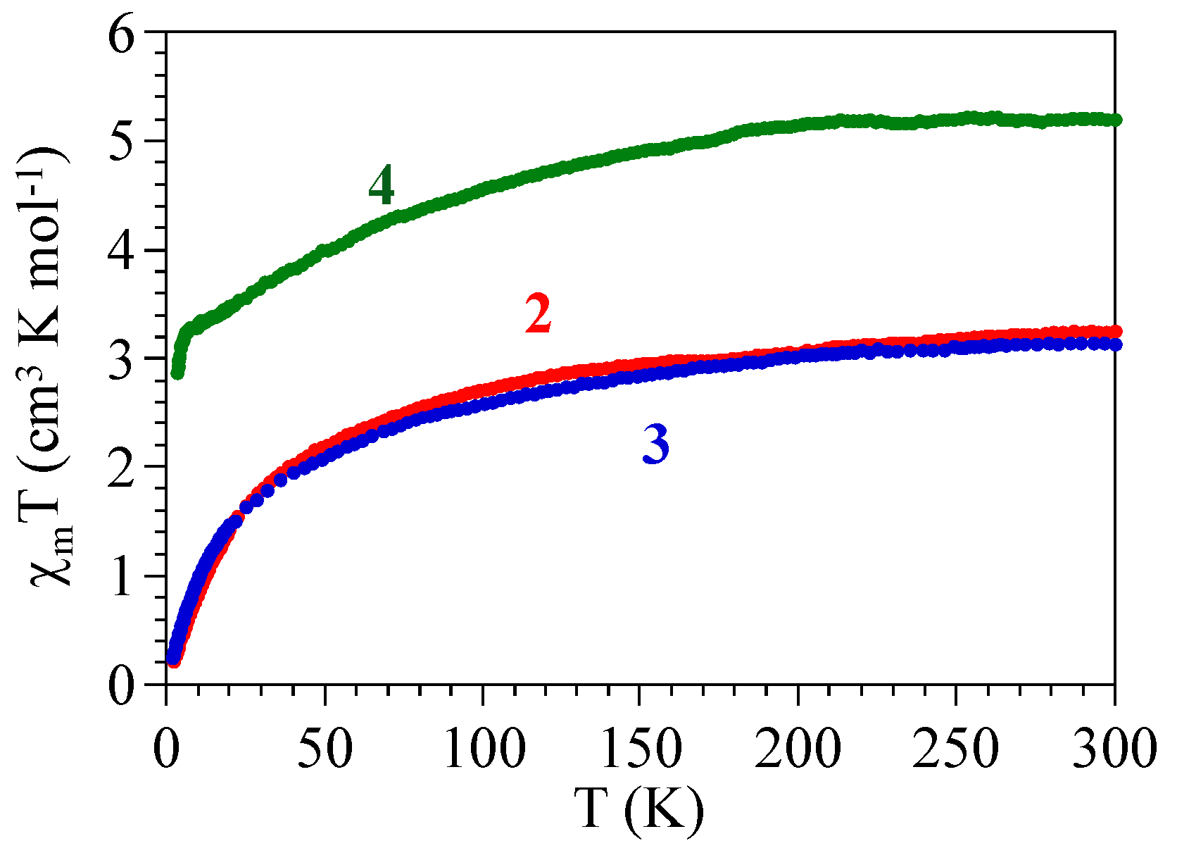
2.3. Magnetic Properties

The magnetic properties of compounds 24 show the expected behaviours for isolated or quasi-isolated Pr(III) (in compounds 2 and 3) or Yb(III) (in compound 4) ions. Thus, the product of the magnetic susceptibility times the temperature (χmT) per formula (i.e., per two Ln(III) ions) is ca. 3.15, 3.25, and 5.20 cm3 K mol−1 for compounds 2, 3 and 4, respectively, close to the expected values for the corresponding isolated Ln(III) ions (3.20 cm3 K mol−1 with g = 4/5 for compounds 2 and 3, or 5.14 cm3 K mol−1 with g = 8/7 for compound 4, Figure 12). When the samples are cooled, χmT shows a progressive decrease in the three compounds, reaching values of ca. 0.2, 0.2 and 2.8 cm3 K mol−1 at 2 K for 24, respectively.
The observed χmT values at room temperature are close to those calculated for 3H4 (in compounds 2 and 3) or 2F7/2 ground multiplets (in compound 4) [44]. The decrease observed in the three compounds can be attributed to the progressive depopulation of the higher energy Stark levels that arise from the splitting of the 3H4 and 2F7/2 ground levels, due to the ligand field. This decrease may also include a very weak antiferromagnetic Ln-Ln coupling through the chlorocyananilato bridge.
The observed behaviour indicates that compounds 24 are essentially paramagnetic and, therefore, also indicates that the chlorocyananilato bridge gives rise to very weak (if any) magnetic coupling, in agreement with the observed behaviour when the anilato-type ligands connect transition metals [27,29,30] or Ln(III) ions [33,36,37].

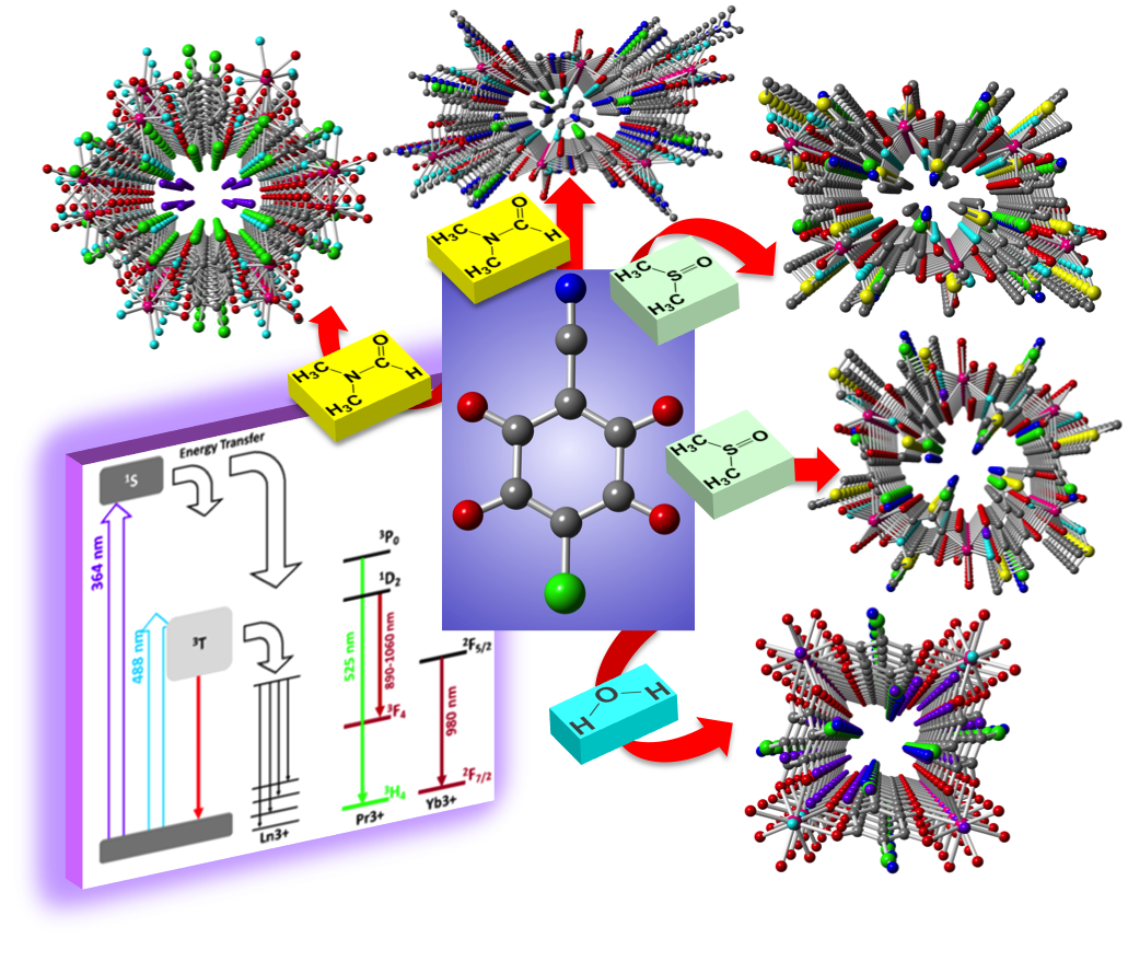
2.4. Luminescent Properties

In compounds 24, the energy transfer is activated via the 2-chloro-5-cyano-3,6-dihydroxybenzoquinone ligand. Therefore, the contribution of the ligand to the light emissions must be taken into account, since, in certain situations, such emissions could be as intense as the lanthanide contribution. In solution the luminescence of the chlorocyananilato ligand shows a broad emission band centred at ca. 550 nm, with a full width at half-maximum (FWHM) of ca. 90 nm, corresponding to a 3T → 0S transition. This transition can be excited with light by direct population of the 1S state, using short wavelengths (UV excitation) [39]. However, the optical properties of the chromophores may vary after crystallization [37] and, therefore, the measurements in solution may not be representative of our compounds. Accordingly, we have measured, as a reference, the chlorocyananilato ligand as its potassium salt K2(C6O4(CN)Cl), in the same conditions as for the crystals of compounds 24. These measurements show very similar spectra for the potassium salt and for compounds 24 when using UV light (364 nm), see Figure 13. These spectra consist of a broad band centred at ca. 675 nm, with a FWHM of about 120 nm. We can, therefore, point out a notable red shift and broadening of the band in solid state, with respect to the emission found in solution [39].
The emission spectra of compounds 2 and 4 were measured under UV (364 nm) and visible excitation (488 nm), obtaining similar results. Exciting with UV light, we can identify two different kinds of bands in both compounds, labelled in Figure 14a as PS and PL, respectively. The main difference is the presence of a third peak at the near-infrared in compound 4, labelled as PYb. This peak is the well-known signature of the Yb(III) ion, and it corresponds to the transition 2F5/22F7/2 [45]. Since 2F5/2 is the only excited state of the Yb(III), no more peaks can be ascribed to this ion. The peak PS corresponded to the substrate background (SiO2), as we concluded by measuring in a clear area without crystals. This peak avoids the distinction of the ligand emission that could be related to PL. To shed light on this, we can compare peak PS with the results obtained under visible light excitation (488 nm) in Figure 14b. In this figure, the spectra are normalized to the PL peak. This way, we see that PS can not be observed when exciting with visible light. Moreover, we show that there is not a great difference in the emission of both samples, except by PYb. The point is that the substrate is transparent in the visible light, and then it does not show luminescence when excited at 488 nm. After removing the contribution of the substrate, PL perfectly fits with the chlorocyananilato ligand salt emission in terms of emission energy and broadening (see Figure 13). As a result, we can conclude that in compound 2 the luminescence comes from the ligand, without clear insights of the Pr(III) ion contribution.
With these results, we can tentatively propose the energy transfer diagram depicted in Figure 15 to discuss about the sensitization mechanism. As proposed in this diagram, the dynamics for each compound under UV and visible excitation are associated to the same energy transfer pathways. The only difference is that the UV light (364 nm) excites the compound to the 1S level of the ligand. At this point, an important part of this energy would be transferred to the 3T state. Under visible light excitation (488 nm) the light absorption is considerable lower, and then higher excitation powers are required. As an advantage, the 3T state is directly excited, leading to similar results, but avoiding the substrate background. As occurs in solid-state systems, the excitation of 3T is quickly thermalized at the bottom of the band. Since transitions from 3T → 0S usually require long lifetimes, the energy accumulated at the bottom of the band can be transferred to lower energy levels (i.e., the Ln(III) ions can be sensitized). In the case of compound 4, this mechanism is clearly favoured by thermalization, because 2F5/2 is located at an energy level slightly lower than that of the 3T band. Indeed, PL almost overlaps with PYb in the emission spectra. In contrast, in the case of compound 2, a poor or negligible sensitization is expected. The reasons are: (i) the most active optical transitions of Pr(III) ions arise from 3P0 which, as it is located at higher energy, is not exposed to sensitization and (ii) the closest energy level (1D2) is located at the high-energy side of 3T and hence, the energy reaching 3T is quickly thermalized, reducing sensitization probability [46]. It is also worth noting that even existing certain energy transfer to 1D2, the oscillator strength of the transition 1D23H4 is very weak and, furthermore, it is in competition with a parallel deactivation channel in the infra-red spectrum (1D23F4) (see Figure 15).
Finally, compound 3 does not show any significant emission when excited at 488 nm, and the luminescence signal is very weak when excited at 364 nm. Indeed, the luminescence emission coming from this compound is comparable to the luminescence emission coming from the substrate, except for a weak contribution appearing as a shoulder at ca. 680 nm that may correspond to the emission of the ligand itself (Figure 16).

3. Experimental Section

3.1. Starting Materials

The Ln(III) nitrates Ce(NO3)3·6H2O, Pr(NO3)3·6H2O and Dy(NO3)3·xH2O, as well as all the solvents used in this work, are commercially available and were used as received. The chlorocyananilato ligand in the form of K2[C6O4(CN)Cl], KH[C6O4(CN)Cl] or [Ph4P]2[C6O4(CN)Cl]·2H2O was prepared following the literature [39].

3.2. Synthesis of [Ce2(C6O4Cl(CN))3(DMF)6]·2H2O (1)

Compound 1 was obtained as single crystals by carefully layering, at room temperature, a solution of Ce(NO3)3·6H2O (8.68 mg, 0.02 mmol) in 5 mL of methanol, on top of a solution of KH[C6O4(CN)Cl] (4.75 mg, 0.02 mmol) in 5 mL of dimethylformamide (DMF). The tube was sealed and allowed to stand for about ten days to obtain red block crystals. Suitable crystals for X-ray diffraction were filtered and air-dried.

3.3. Synthesis of [Pr2(C6O4(CN)Cl)3(DMF)6] (2)

Compound 2 was obtained as single crystals by carefully layering, at room temperature, a solution of Pr(NO3)3·6H2O (4.35 mg, 0.01 mmol) in 2.5 mL of methanol, on top of a solution of K2[C6O4(CN)Cl] (4.14 mg, 0.015 mmol) in 2.5 mL of DMF. The tube was sealed and left to stand at room temperature for about two weeks to obtain red prismatic crystals. Suitable crystals for X-ray diffraction were filtered and air dried.

3.4. Synthesis of [Pr2(C6O4(CN)Cl)3(DMSO)6] (3)

Compound 3 was obtained as single crystals by carefully layering, at room temperature, a solution of Pr(NO3)3·6H2O (4.35 mg, 0.01 mmol) in 2.5 mL of methanol, on top of a solution of K2[C6O4(CN)Cl] (4.14 mg, 0.015 mmol) in 2.5 mL of DMSO. The tube was sealed and left to stand at room temperature for about ten days to obtain red prismatic crystals. Suitable crystals for X-ray diffraction were filtered and air dried.

3.5. Synthesis of [Yb2(C6O4(CN)Cl)3(DMSO)4]·2H2O (4)

Compound 4 was obtained as single crystals by carefully layering, at room temperature, a solution of Yb(NO3)3·5H2O (4.5 mg, 0.01 mmol) in 2.5 mL of methanol, on top of a solution of K2[C6O4(CN)Cl] (4.14 mg, 0.015 mmol) in 2.5 mL of DMSO. The tube was sealed and left to stand at room temperature for about ten days to obtain red prismatic crystals. Suitable crystals for X-ray diffraction were filtered and air dried.

3.6. Synthesis of (H3O)[Dy(C6O4Cl(CN))2(H2O) ]·4H2O (5)

Compound 5 was obtained as single crystals by carefully layering, at room temperature, a solution of [Ph4P]2[C6O4(CN)Cl]·2H2O (9.2 mg, 0.01 mmol) in 2.5 mL of methanol, on top of a solution of Dy(NO3)3·xH2O (3.48 mg, ca. 0.01 mmol) in 2.5 mL of water. The tube was sealed and left to stand at room temperature for about ten days to obtain pink plate-like crystals. Suitable crystals for X-ray diffraction were filtered and air dried.

3.7. Magnetic Measurements

Magnetic susceptibility measurements were carried out in the temperature range 2–300 K, with an applied magnetic field of 0.5 T on polycrystalline samples of compounds 24 with a Quantum Design MPMS-XL-5 SQUID susceptometer (San Diego, CA, USA). For compounds 1 and 5 only a small amount of single crystals could be obtained, not enough to perform magnetic measurements. The susceptibility data were corrected for the sample holders previously measured, using the same conditions and for the diamagnetic contributions of the salt as deduced by using Pascal’s constant tables [47].

3.8. Luminesce Measurements

Isolated crystals were located in a SiO2 substrate. Then, luminescence measurements were carried out, holding the substrate in a positioning stage with micrometer resolution and exciting the sample with two Ar lasers, respectively operating at 488 nm (visible) and 364 nm (ultraviolet) in continuous wave. Both lasers were aligned on the same optical path, so they could be consecutively used at the same measuring point. The excitation was focused using a large focal length microscope objective, driving to a spot size of few micrometers. A beam splitter was employed to collect the luminescence using the same objective (back-scattering configuration). The collected light was dispersed by a 1 m focal length spectrograph, and detected with a silicon detector. It is worth noting that we have not found significant differences when comparing the emission from different crystals of the same compound, only variations in the light intensity that we can attribute to the geometry and orientation of a given crystal. Luminescence measurements of samples of compounds 1 and 5, as well as of other compounds with this ligand and different Ln(III) ions, are in progress and will be reported elsewhere.

3.9. Crystallographic Data Collection and Refinement

Suitable single crystals of compounds 15 were mounted on a glass fibre, using a viscous hydrocarbon oil, and then transferred directly to the cold nitrogen stream for data collection. X-ray data were collected at 120 K on a Supernova Agilent Technologies diffractometer equipped with a graphite-monochromated Enhance (Mo) X-ray Source (λ = 0.71073 Å). The program CrysAlisPro, Agilent Technologies Ltd., was used for unit cell determinations and data reduction. Empirical absorption correction was performed using spherical harmonics, implemented in the SCALE3 ABSPACK scaling algorithm. Crystal structures were solved with direct methods with the SIR97 program [48], and refined against all F2 values with the SHELXL-2014 program [49], using the WinGX graphical user interface [50]. All non-hydrogen atoms were refined anisotropically, and hydrogen atoms were placed in calculated positions and refined isotropically with a riding model. Data collection and refinement parameters are given in Table 5.
CCDC-1588403, 1529644, 1529642, 1529643 and 1588404 contain the supplementary crystallographic data for compounds 15, respectively. These data can be obtained free of charge from The Cambridge Crystallographic Data Centre at www.ccdc.cam.ac.uk/data_request/cif.

4. Conclusions

The combination of the Ln(III) ions Ce(III), Pr(III), Yb(III) and Dy(III) with the anilato-type ligand chlorocyananilato, using different coordinating solvents as H2O, DMSO and DMF, has resulted in the formation of five new compounds, formulated as [Ce2(C6O4(CN)Cl)3(DMF)6]·2H2O (1), [Pr2(C6O4(CN)Cl)3(DMF)6] (2), [Pr2(C6O4(CN)Cl)3(DMSO)6] (3), [Yb2(C6O4(CN)Cl)3(DMSO)4]·2H2O (4) and [H3O][Dy(C6O4(CN)Cl)2(H2O)]·4H2O (5). Compounds 14 show honeycomb (6,3)-2D lattices with different distortions of the hexagonal cavities. In contrast, compound 5 shows a square (4,4)-2D lattice only previously observed in one anilato-based compound.
These compounds show the important role played by the size of the Ln(III) ion, as well as the size and shape of the coordinating solvent molecules, in determining the structure of the compounds. For example, compounds 1 and 2, prepared with the same solvent (DMF) but with different metal ions (Ce and Pr), show the important role of a small variation of the Ln(III) size: the larger Ce(III) ion allows a coordination number of nine, with a distorted tri-capped trigonal prismatic geometry that led to corrugated hexagonal layers with regular hexagonal cavities, whereas the slightly smaller Pr(III) ion gives rise to a distorted mono-capped square antiprism coordination geometry that generates rectangular cavities. The key role of the solvent is shown with compounds 2 and 3, which have the same metal, Pr(III), and ligand, and only differ in the solvent molecule used (DMF in compound 2 and DMSO in compound 3). Here, the coordination number was nine in both compounds, but the change of DMF by DMSO produced a change in the coordination geometry (mono-capped square antiprism in compound 2 and tri-capped triangular prism in compound 3). This change in geometry is attributed to the larger steric effect produced by DMSO compared to that of DMF, giving rise to a different orientation of the bridging anilato ligand and, accordingly, to a different distortion of the cavities and of their orientation in the layer. A further confirmation of the role of the size of the Ln(III) ion was provided by compounds 3 and 4, which were prepared with the same solvent (DMSO) but with different metal ions, Pr (compound 3) and Yb (compound 4). The smaller Yb(III) ion has a coordination number of eight, whereas the larger Pr(III) ion has a coordination number of nine. Although both compounds also present the same (6,3)-2D topology, the change in the coordination number leads to changes in the coordination geometry and in the distortions of the hexagonal cavities.
Compound 5, the only one prepared with water as solvent, is different to all the others, since the Ln(III) ion is surrounded by four anilato ligands (instead of three). This different coordination (and stoichiometry) generates a unique (4,4)-2D square lattice in compound 5, with water molecules in the inter-layer space.
The magnetic properties of the compounds confirm the weak (if any) magnetic coupling produced by the anilato type ligands when connecting Ln(III) ions, in agreement with all the previous studies of anilato-bridged Ln(III) compounds.
The luminescent properties of the chlorocyananilato ligand and of compounds 24, show a red shift and a broadening of the typical emission band of the ligand when combined with Ln(III). Additionally, compound 4 shows a strong emission band at ca. 980 nm, corresponding to the Yb(III) ions as expected from the proposed energy transfer diagram. Compound 3 showed only a weak band, similar to the ligand emission.
The synthesis of the complete Ln(III) series with this ligand and different coordinating solvents as formamide and dimethylacetamide, in addition to the already-used H2O, DMF, and DMSO is under investigation.

Acknowledgments

We thank the Generalitat Valenciana (project PrometeoII/2014/076) and the Spanish MINECO (project CTQ2017-87201-P) for financial support.

Author Contributions

S.B. designed the synthesis, performed the X-ray structural analysis and supervised all the experiments. P.G.C., C.C.N. and A.H.P. performed the synthesis of the ligand and of the compounds. J.C., C.R.-F. and A.C. performed the luminescence measurements. C.J.G.G. performed the magnetic measurements and supervised all the experiments. All the authors contributed to the writing of the manuscript.

Conflicts of Interest

The authors declare no conflict of interest.

References

  1. Zhou, H.C.; Long, J.R.; Yaghi, O.M. Introduction to metal-organic frameworks. Chem. Rev. 2012, 112, 673–674. [Google Scholar] [CrossRef] [PubMed]
  2. Furukawa, H.; Cordova, K.E.; O’Keeffe, M.; Yaghi, O.M. The chemistry and applications of metal-organic frameworks. Science 2013, 341, 1230444. [Google Scholar] [CrossRef] [PubMed]
  3. Barea, E.; Montoro, C.; Navarro, J.A. Toxic gas removal-metal-organic frameworks for the capture and degradation of toxic gases and vapours. Chem. Soc. Rev. 2014, 43, 5419–5430. [Google Scholar] [CrossRef] [PubMed]
  4. Schoedel, A.; Ji, Z.; Yaghi, O.M. The role of metal-organic frameworks in a carbon-neutral energy cycle. Nat. Energy 2016, 1, 16034. [Google Scholar] [CrossRef]
  5. Canivet, J.; Fateeva, A.; Guo, Y.; Coasne, B.; Farrusseng, D. Water adsorption in MOFs: Fundamentals and applications. Chem. Soc. Rev. 2014, 43, 5594–5617. [Google Scholar] [CrossRef] [PubMed]
  6. Wang, L.; Han, Y.; Feng, X.; Zhou, J.; Qi, P. Metal–organic frameworks for energy storage: Batteries and supercapacitors. Coord. Chem. Rev. 2016, 307, 361–381. [Google Scholar] [CrossRef]
  7. Bai, S.; Liu, X.; Zhu, K.; Wu, S.; Zhou, H. Metal–organic framework-based separator for lithium–sulfur batteries. Nat. Energy 2016, 1, 16094. [Google Scholar] [CrossRef]
  8. Nandasiri, M.I.; Jambovane, S.R.; McGrail, B.P.; Schaef, H.T.; Nune, S.K. Adsorption, separation, and catalytic properties of densified metal-organic frameworks. Coord. Chem. Rev. 2016, 311, 38–52. [Google Scholar] [CrossRef]
  9. Huang, Y.B.; Liang, J.; Wang, X.S.; Cao, R. Multifunctional metal-organic framework catalysts: Synergistic catalysis and tandem reactions. Chem. Soc. Rev. 2017, 46, 126–157. [Google Scholar] [CrossRef] [PubMed]
  10. Kreno, L.E.; Leong, K.; Farha, O.K.; Allendorf, M.; Van Duyne, R.P.; Hupp, J.T. Metal-organic framework materials as chemical sensors. Chem. Rev. 2012, 112, 1105–1125. [Google Scholar] [CrossRef] [PubMed]
  11. Campbell, M.G.; Dinca, M. Metal-Organic Frameworks as Active Materials in Electronic Sensor Devices. Sensors 2017, 17, 1108. [Google Scholar] [CrossRef] [PubMed]
  12. Horcajada, P.; Gref, R.; Baati, T.; Allan, P.K.; Maurin, G.; Couvreur, P.; Ferey, G.; Morris, R.E.; Serre, C. Metal-organic frameworks in biomedicine. Chem. Rev. 2012, 112, 1232–1268. [Google Scholar] [CrossRef] [PubMed]
  13. Wu, M.X.; Yang, Y.W. Metal-Organic Framework (MOF)-Based Drug/Cargo Delivery and Cancer Therapy. Adv. Mater. 2017, 29, 1606134. [Google Scholar] [CrossRef] [PubMed]
  14. Li, B.; Wen, H.M.; Cui, Y.; Zhou, W.; Qian, G.; Chen, B. Emerging Multifunctional Metal-Organic Framework Materials. Adv. Mater. 2016, 28, 8819–8860. [Google Scholar] [CrossRef] [PubMed]
  15. Fordham, S.; Wang, X.; Bosch, M.; Zhou, H. Lanthanide Metal-Organic Frameworks: Syntheses, Properties, and Potential Applications. In Structure and Bonding; Springer: Berlin, Germany, 2015; Volume 163, pp. 1–27. [Google Scholar]
  16. Wang, C.; Liu, X.; Keser Demir, N.; Chen, J.P.; Li, K. Applications of water stable metal-organic frameworks. Chem. Soc. Rev. 2016, 45, 5107–5134. [Google Scholar] [CrossRef] [PubMed]
  17. Liu, X.; Fu, W.; Bouwman, E. One-step growth of lanthanoid metal-organic framework (MOF) films under solvothermal conditions for temperature sensing. Chem. Commun. (Camb.) 2016, 52, 6926–6929. [Google Scholar] [CrossRef] [PubMed]
  18. Zhang, W.; Zhang, W.; Wang, R.; Ren, C.; Li, Q.; Fan, Y.; Liu, B.; Liu, P.; Wang, Y. Effect of Coordinated Solvent Molecules on Metal Coordination Sphere and Solvent-Induced Transformations. Cryst. Growth Des. 2017, 17, 517–526. [Google Scholar] [CrossRef]
  19. Li, X.; Sun, X.; Li, X.; Fu, Z.; Su, Y.; Xu, G. Porous Cadmium(II) Anionic Metal-Organic Frameworks Based on Aromatic Tricarboxylate Ligands: Encapsulation of Protonated Flexible Bis(2-methylimidazolyl) Ligands and Proton Conductivity. Cryst. Growth Des. 2015, 15, 4543–4548. [Google Scholar] [CrossRef]
  20. Sun, L.; Qi, Y.; Che, Y.; Batten, S.R.; Zheng, J. Three Unprecedented Entangled Metal-Organic Frameworks: Self-Penetration and Hydrothermal in Situ Ligand Formation. Cryst. Growth Des. 2009, 9, 2995–2998. [Google Scholar] [CrossRef]
  21. Zhao, D.; Timmons, D.J.; Yuan, D.; Zhou, H.C. Tuning the topology and functionality of metal-organic frameworks by ligand design. Acc. Chem. Res. 2011, 44, 123–133. [Google Scholar] [CrossRef] [PubMed]
  22. Kitagawa, S.; Kawata, S. Coordination compounds of 1,4-dihydroxybenzoquinone and its homologues. Structures and properties. Coord. Chem. Rev. 2002, 224, 11–34. [Google Scholar] [CrossRef]
  23. Mercuri, M.L.; Congiu, F.; Concas, G.; Sahadevan, S.A. Recent Advances on Anilato-Based Molecular Materials with Magnetic and/or Conducting Properties. Magnetochemistry 2017, 3, 17. [Google Scholar] [CrossRef]
  24. Atzori, M.; Artizzu, F.; Sessini, E.; Marchio, L.; Loche, D.; Serpe, A.; Deplano, P.; Concas, G.; Pop, F.; Avarvari, N.; et al. Halogen-bonding in a new family of tris(haloanilato)metallate(III) magnetic molecular building blocks. Dalton Trans. 2014, 43, 7006–7019. [Google Scholar] [CrossRef] [PubMed]
  25. Benmansour, S.; Gómez-Claramunt, P.; Vallés-García, C.; Mínguez Espallargas, G.; Gómez García, C.J. Key Role of the Cation in the Crystallization of Chiral Tris(Anilato)Metalate Magnetic Anions. Cryst. Growth Des. 2016, 16, 518–526. [Google Scholar] [CrossRef]
  26. Abrahams, B.F.; Grannas, M.J.; Hudson, T.A.; Hughes, S.A.; Pranoto, N.H.; Robson, R. Synthesis, structure and host-guest properties of (Et4N)2[SnIVCaII(chloranilate)4], a new type of robust microporous coordination polymer with a 2D square grid structure. Dalton Trans. 2011, 40, 12242–12247. [Google Scholar] [CrossRef] [PubMed]
  27. Atzori, M.; Benmansour, S.; Mínguez Espallargas, G.; Clemente-León, M.; Abhervé, A.; Gómez-Claramunt, P.; Coronado, E.; Artizzu, F.; Sessini, E.; Deplano, P.; et al. A Family of Layered Chiral Porous Magnets Exhibiting Tunable Ordering Temperatures. Inorg. Chem. 2013, 52, 10031–10040. [Google Scholar] [CrossRef] [PubMed]
  28. Benmansour, S.; Vallés-García, C.; Gómez-Claramunt, P.; Mínguez Espallargas, G.; Gómez-García, C.J. 2D and 3D Anilato-Based Heterometallic M(I)M(III) Lattices: The Missing Link. Inorg. Chem. 2015, 54, 5410–5418. [Google Scholar] [CrossRef] [PubMed]
  29. Benmansour, S.; Gómez-García, C.J. A Heterobimetallic Anionic 3,6-Connected 2D Coordination Polymer Based on Nitranilate as Ligand. Polymers 2016, 8, 89. [Google Scholar] [CrossRef]
  30. Benmansour, S.; Abhervé, A.; Gómez-Claramunt, P.; Vallés-García, C.; Gómez-García, C.J. Nanosheets of Two-Dimensional Magnetic and Conducting Fe(II)/Fe(III) Mixed-Valence Metal–Organic Frameworks. ACS Appl. Mater. Interfaces 2017, 9, 26210–26218. [Google Scholar] [CrossRef] [PubMed]
  31. Abrahams, B.F.; Coleiro, J.; Ha, K.; Hoskins, B.F.; Orchard, S.D.; Robson, R. Dihydroxybenzoquinone and chloranilic acid derivatives of rare earth metals. J. Chem. Soc. Dalton Trans. 2002, 1586–1594. [Google Scholar] [CrossRef]
  32. Abrahams, B.F.; Coleiro, J.; Hoskins, B.F.; Robson, R. Gas hydrate-like pentagonal dodecahedral M2(H2O)18 cages (M = lanthanide or Y) in 2,5-dihydroxybenzoquinone-derived coordination polymers. Chem. Commun. 1996, 603–604. [Google Scholar] [CrossRef]
  33. López-Martínez, G. Multifunctionality in Molecular Materials Based on Anilato-Type Ligands. Ph.D. Thesis, University of Valencia, Valencia, Spain, June 2017. [Google Scholar]
  34. Christian, R. Complexes with substituted 2,5-dihydroxy-p-benzoquinones: The inclusion compounds [Y(H2O)3]2 (C6Cl2O4)3·6.6H2O and [Y(H2O)3]2 (C6Br2O4)3·6H2O. Mater. Res. Bull. 1987, 22, 1483–1491. [Google Scholar]
  35. Riley, P.E.; Haddad, S.F.; Raymond, K.N. Preparation of praseodymium(III) chloranilate and the crystal structures of Pr2(C6Cl2O4)3·8C2H5OH and Na3[C6H2O(OH)(SO3)2] H2O. Inorg. Chem. 1983, 22, 3090–3096. [Google Scholar] [CrossRef]
  36. Benmansour, S.; Pérez-Herráez, I.; López-Martínez, G.; Gómez García, C.J. Solvent-modulated structures in anilato-based 2D coordination polymers. Polyhedron 2017, 135, 17–25. [Google Scholar] [CrossRef]
  37. Benmansour, S.; López-Martínez, G.; Canet-Ferrer, J.; Gómez-García, C.J. A Family of Lanthanoid Dimers with Nitroanilato Bridges. Magnetochemistry 2016, 2, 32. [Google Scholar] [CrossRef]
  38. Benmansour, S.; Hernández-Paredes, A.; Gómez-García, C.J. Size-dependence of the structure in a series of lanthanoid-anilato 2D lattices. J. Coord. Chem. 2018, in press. [Google Scholar] [CrossRef]
  39. Atzori, M.; Artizzu, F.; Marchio, L.; Loche, D.; Caneschi, A.; Serpe, A.; Delano, P.; Avarvari, N.; Mercuri, M.L. Switching-on luminescence in anilate-based molecular materials. Dalton Trans. 2015, 44, 15786–15802. [Google Scholar] [CrossRef] [PubMed] [Green Version]
  40. Rehwoldt, R.E.; Chasen, B.; Li, J. 2-Chloro-5-Cyano-3,6-Dihydroxybenzoquinone, a New Analytical Reagent for the Spectrophotometric Determination of Calcium(II). Anal. Chem. 1966, 38, 1018–1019. [Google Scholar] [CrossRef]
  41. Diaz-Torres, R.; Alvarez, S. Coordinating ability of anions and solvents towards transition metals and lanthanides. Dalton Trans. 2011, 40, 10742–10750. [Google Scholar] [CrossRef] [PubMed]
  42. Imaz, I.; Mouchaham, G.; Roques, N.; Brandès, S.; Sutter, J. Tetradihydrobenzoquinonate and Tetrachloranilate Zr(IV) Complexes: Single-Crystal-to-Single-Crystal Phase Transition and Open-Framework Behavior for K4Zr(DBQ)4. Inorg. Chem. 2013, 52, 11237–11243. [Google Scholar] [CrossRef] [PubMed]
  43. Mouchaham, G.; Roques, N.; Duhayon, C.; Imaz, I.; Sutter, J. Extended H-bond networks based on guanidinium H-donors and [Zr(A)4]4− H-acceptor units: Modulation of the assemblage and guest accessible volume by chemical design (A = oxalate, dihydrobenzoquinonate, chloranilate). New J. Chem. 2013, 37, 3476–3487. [Google Scholar] [CrossRef]
  44. Sorace, L.; Gatteschi, D. Electronic Structure and Magnetic Properties of Lanthanide Molecular Complexes. In Lanthanides and Actinides in Molecular Magnetism; Layfield, R.A., Murugesu, M., Eds.; Wiley-VCH: Weinheim, Germany, 2015; Volume 1, pp. 1–25. [Google Scholar]
  45. Sontakke, A.D.; Ueda, J.; Katayama, Y.; Zhuang, Y.; Dorenbos, P. Role of electron transfer in Ce3+ sensitized Yb3+ luminescence in borate glass. J. Appl. Phys. 2015, 117, 013105. [Google Scholar] [CrossRef] [Green Version]
  46. Kristianpoller, N.; Shmilevich, A.; Weiss, D.; Chen, R.; Khaidukov, N. Luminescence of LiKYF5:Pr3 crystals. Radiat. Meas. 2001, 33, 637–640. [Google Scholar] [CrossRef]
  47. Bain, G.A.; Berry, J.F. Diamagnetic corrections and Pascal’s constants. J. Chem. Educ. 2008, 85, 532–536. [Google Scholar] [CrossRef]
  48. Altomare, A.; Burla, M.C.; Camalli, M.; Cascarano, G.L.; Giacovazzo, C.; Guagliardi, A.; Moliterni, A.G.G.; Polidori, G.; Spagna, R. SIR97: A new tool for crystal structure determination and refinement. J. Appl. Crystallogr. 1999, 32, 115–119. [Google Scholar] [CrossRef]
  49. Sheldrick, G.M. Crystal structure refinement with SHELXL. Acta Crystallogr. C 2015, 71, 3–8. [Google Scholar] [CrossRef] [PubMed]
  50. Farrugia, L.J. WinGX and ORTEP for Windows: An update. J. Appl. Crystallogr. 2012, 45, 849–854. [Google Scholar] [CrossRef]
Figure 1. (a) The ligand dhbq2− and the 3,6-disubstituted anilato derivative dianions (C6O4X2)2− showing the typical bis-bidentate coordination mode displayed by oxalato (b).
Magnetochemistry 04 00006 g001
Figure 2. (a) Side view of the corrugated layers in compound 1. Only the oxygen atoms of the dimethylformamide (DMF) molecules are shown and the H atoms have been omitted for clarity. (b) Projection of the hexagonal layer in the ab plane. Colour code: Ce = pink, Cl = green, C = grey, O = red, N = dark blue, ODMF = light blue and Owater = purple.
Magnetochemistry 04 00006 g002
Figure 3. (a) Perspective view of one hexagonal channel along the [101] direction in compound 1. Only the oxygen atoms of the DMF molecules are shown, and the N atoms of the CN groups and the H atoms have been omitted for clarity. (b) Coordination environment of the Ce atom in compound 1, with the labelling scheme of the main atoms and the disorder in the Cl/CN positions. (c) Coordination geometry of the Ce atom in compound 1. Colour code: Ce = pink, Cl = green, C = grey, O = red, N = dark blue, ODMF = light blue and Owater = purple. Due to the Cl/CN disorder, the Cl atoms represent 50% Cl and 50% C of the CN group.
Magnetochemistry 04 00006 g003
Figure 4. (a) Side view of the layers in compound 2. (b) View of one rectangular layer in compound 2. Only the oxygen atoms of the DMF molecules are shown. H atoms have been omitted for clarity. Colour code: Pr = pink, Cl = green, C = grey, O = red, N = dark blue and ODMF = light blue.
Magnetochemistry 04 00006 g004
Figure 5. (a) Perspective view of a rectangular channel along the a direction in compound 2. (b) Coordination environment of the Pr atom in compound 2, with the labelling scheme of the main atoms and the disorder in the Cl/CN positions. (c) Coordination geometry of the Pr atom in 2. Colour code: Pr = pink, Cl = green, C = grey, O = red, N = dark blue and ODMF = light blue.
Magnetochemistry 04 00006 g005
Figure 6. (a) Side view of the corrugated layers in compound 3. (b) View of the distorted hexagonal cavities in compound 3, in the direction perpendicular to the layer. The Cl and CN groups of the anilato ligands have been omitted, and only the O atom of the dimethylsolfoxide (DMSO) molecules is displayed for clarity. Colour code: Pr = pink, C = grey, O = red, ODMSO = light blue.
Magnetochemistry 04 00006 g006
Figure 7. (a) Perspective view of a distorted hexagonal channel along the a direction in 3. (b) Coordination environment of the Pr atom in compound 3 with the labelling scheme of the main atoms. Only one of the two possible positions of the Cl and CN groups is displayed. (c) Coordination geometry of the Pr atom in compound 3. Colour code: Pr = pink, Cl = green, C = grey, O = red, N = dark blue, ODMSO = light blue, S = yellow.
Magnetochemistry 04 00006 g007
Figure 8. (a) Side view of the layers in compound 4. (b) View of the distorted hexagonal cavities in compound 4 along the a direction. Colour code: Yb = pink, Cl = green, C = grey, O = red, N = dark blue, ODMSO = light blue, S = yellow.
Magnetochemistry 04 00006 g008
Figure 9. (a) Perspective view of a distorted hexagonal channel along the a direction in compound 4. (b) Coordination environment of the Yb atom in compound 4 with the labelling scheme of the main atoms. (c) Coordination geometry of the Yb atom in compound 4. Colour code: Yb = pink, Cl = green, C = grey, O = red, N = dark blue, ODMSO = light blue, S = yellow.
Magnetochemistry 04 00006 g009
Figure 10. (a) Side view of the layers in compound 5. (b) View of the (4,4)-2D square lattice in compound 5 along the b direction. Colour code: Dy = pink, Cl = green, C = grey, O = red, N = dark blue, O (coordinated water) = light blue, O (crystallization water) = purple.
Magnetochemistry 04 00006 g010
Figure 11. (a) Perspective view of a square channel along the a direction in compound 5. (b) Coordination environment of the Dy atom in compound 5 with the labelling scheme of the main atoms. (c) Coordination geometry of the Dy atom in 5. Colour code: Dy = pink, Cl = green, C = grey, O = red, N = dark blue, O (coordinated water) = light blue, O (crystallization water) = purple.
Magnetochemistry 04 00006 g011
Figure 12. Thermal variation of the χmT product for compounds 24.
Magnetochemistry 04 00006 g012
Figure 13. Emission spectra of the salt K2[C6O4(CN)Cl] in solid state under UV excitation (364 nm, blue dots) and under visible excitation (488 nm, purple dots).
Magnetochemistry 04 00006 g013
Figure 14. (a) Emission spectra of compounds 2 (in blue) and 4 (in red). Excited at 488 nm wavelength, the spectra are normalized to the PL band. (b) Emission spectra of the same crystals excited at 364 nm. In this case normalization is referred to the maximum of the spectrum.
Magnetochemistry 04 00006 g014
Figure 15. Diagram for the main pathways available for energy transfer and sensitization in compounds 2 and 4.
Magnetochemistry 04 00006 g015
Figure 16. Luminescence spectrum of compound 3 (in blue) with 364 nm excitation, compared with the substrate signal (in black).
Magnetochemistry 04 00006 g016
Table 1. The series [Ln2(L)3(H2O)6]·18H2O with L = dhbq2− = (C6O4H2)2−.
Ln(III)CompoundPhaseCavityRef.
La[La2(dhbq)3(H2O)6]·18H2OIhex-regular[31]
Ce[Ce2(dhbq)3(H2O)6]·18H2OIhex-regular[31]
Pr[Pr2(dhbq)3(H2O)6]·18H2OIhex-regular[33]
Nd[Nd2(dhbq)3(H2O)6]·18H2OIhex-regular[33]
Sm[Sm2(dhbq)3(H2O)6]·18H2OIhex-regular[33]
Eu[Eu2(dhbq)3(H2O)6]·18H2OIhex-regular[33]
Gd[Gd2(dhbq)3(H2O)6]·18H2OIhex-regular[31]
Tb[Tb2(dhbq)3(H2O)6]·18H2OIhex-regular[33]
Dy[Dy2(dhbq)3(H2O)6]·18H2OIhex-regular[33]
Ho[Ho2(dhbq)3(H2O)6]·18H2OIhex-regular[33]
Er[Er2(dhbq)3(H2O)6]·18H2OIhex-regular[33]
Tm[Tm2(dhbq)3(H2O)6]·18H2OIhex-regular[33]
Yb[Yb2(dhbq)3(H2O)6]·18H2OIhex-regular[31]
Table 2. The series [Ln2(L)3(H2O)6]·nH2O with L = (C6O4Cl2)2− = CA.
Ln(III)CompoundPhaseCavityRef.
La[La2(CA)3(H2O)6]·14H2O aIhex-4E-2F[31]
Ce[Ce2(CA)3(H2O)6]·14H2O bIhex-4E-2F[31]
Pr[Pr2(CA)3(H2O)6]·14H2OIhex-4E-2F[31]
Nd[Nd2(CA)3(H2O)6]·14H2O cIhex-4E-2F[31]
Sm[Sm2(CA)3(H2O)6]·12H2OIIhex-4E-2F[33]
Eu[Eu2(CA)3(H2O)6]·12H2OIIhex-4E-2F[31]
Gd[Gd2(CA)3(H2O)6]·12H2O dIIhex-4E-2F[31]
Tb[Tb2(CA)3(H2O)6]·12H2OIIhex-4E-2F[31]
Dy[Dy2(CA)3(H2O)6]·12H2OIIhex-4E-2F[33]
Ho[Ho2(CA)3(H2O)6]·12H2OIIhex-4E-2F[33]
Er[Er2(CA)3(H2O)6]·10H2OIIIhex-2E-4F[33]
Tm[Tm2(CA)3(H2O)6]·8H2OIVrect-4E-2F[33]
Yb[Yb2(CA)3(H2O)6]·8H2OeIVrect-4E-2F[31]
a This compound was reported with n = 7 and we have obtained it with n = 14; b This compound was reported with n ≈ 12 and we have obtained it with n = 14; c only unit cell parameters reported; d This compound was reported with n ≈ 10 and we have obtained it with n = 12; e This compound was reported with n ≈ 6 and we have obtained it with n = 8.
Table 3. The series [Ln2(L)3(H2O)6]·nH2O with L = (C6O4Br2)2− = BA.
Ln(III)D = H2O/G = H2OPhaseCavityRef.
La[La2(BA)3(H2O)6]·12H2OIhex-4E-2F[33]
Ce[Ce2(BA)3(H2O)6]·12H2OIhex-4E-2F[33]
Pr[Pr2(BA)3(H2O)6]·12H2OIhex-4E-2F[33]
Nd[Nd2(BA)3(H2O)6]·12H2OIhex-4E-2F[33]
Sm[Sm2(BA)3(H2O)6]·12H2OIhex-4E-2F[33]
Eu[Eu2(BA)3(H2O)6]·12H2OIhex-4E-2F[33]
Gd[Gd2(BA)3(H2O)6]·12H2OIhex-4E-2F[33]
Tb[Tb2(BA)3(H2O)6]·12H2OIhex-4E-2F[33]
Dy[Dy2(BA)3(H2O)6]·12H2OIhex-4E-2F[33]
Ho[Ho2(BA)3(H2O)6]·12H2OIhex-4E-2F[33]
Er[Er2(BA)3(H2O)6]·12H2OIhex-4E-2F[36]
Tm[Tm2(BA)3(H2O)6]·8H2OIIrect-4E-2F[33]
Yb[Yb2(BA)3(H2O)6]·8H2OIIrect-4E-2F[33]
Table 4. The series [Ln2(L)3(H2O)10]·6H2O with L = (C6O4(NO2)2)2− = NA.
Ln(III)D = H2O/G = H2OPhaseRef.
Sm[Sm2(NA)3(H2O)10]·6H2Odimer[37]
Eu[Eu2(NA)3(H2O)10]·6H2Odimer[33]
Gd[Gd2(NA)3(H2O)10]·6H2Odimer[37]
Tb[Tb2(NA)3(H2O)10]·6H2Odimer[37]
Dy[Dy2(NA)3(H2O)10]·6H2Odimer[37]
Ho[Ho2(NA)3(H2O)10]·6H2Odimer[37]
Er[Er2(NA)3(H2O)10]·6H2Odimer[37]
Table 5. Crystal data and structure refinement of compounds [Ce2(C6O4(CN)Cl)3(DMF)6]·2H2O (1), [Pr2(C6O4(CN)Cl)3(DMF)6] (2), [Pr2(C6O4(CN)Cl)3(DMSO)6] (3), [Yb2(C6O4(CN)Cl)3(DMSO)4]·2H2O (4) and [H3O][Dy(C6O4(CN)Cl)2(H2O)]·4H2O (5).
Compound12345
FormulaC39H46Cl3
N9O20Ce2
C39H42Cl3
N9O18Pr2
C33H36Cl3
N3O18S6Pr2
C29H28Cl3
N3O18S4Yb2
C14H13Cl2N2
O14Dy
F. Wt.1347.421312.981343.211287.24666.66
Space group (#)C2/c (15)P21/n (14)P21/n (14)P-1 (2)P2/n (13)
Crystal systemMonoclinicMonoclinicMonoclinicTriclinicMonoclinic
a (Å)13.8141(3)10.6585(10)9.6262(3)9.935411.9237(4)
b (Å)23.3672(4)13.7163(10)16.3853(4)10.619514.0496(8)
c (Å)17.9855(4)18.3196(14)15.3240(4)10.775212.2263(5)
α (°)909090112.01090
β (°)98.983(2)98.86391.76593.13590.254(4)
γ (°)90909095.1990
V/Å35734.5(2)2646.3(4)2415.88(11)1044.39(7)2048.17(16)
Z42211
T (K) 120120120120120
ρcalc/g cm−31.6381.6331.7972.0211.189
μ/mm−11.9212.0452.4884.9162.009
F(000)279612801256606700
R(int)0.03140.08980.11800.05940.0623
θ range (deg)3.31–25.082.81–25.142.76–25.073.05–25.033.33–25.05
Total reflections19,38035,85838,30010,44814,772
Unique reflections50714705427831803604
Data with I > 2σ (I)44503541315432073264
Nvar342327311289186
R1 a on I > 2σ (I)0.05990.04420.06060.03940.0839
wR2 b (all)0.17730.11390.14970.10100.2384
GOF c on F21.0891.0521.0671.0711.113
Δρmax (eÅ−3)1.8101,6161.4191.7754.534
Δρmin (eÅ−3)−1.980−0,865−1.004−1.100−1.419
a R1 = Σ ||Fo| − |Fc||/Σ |Fo|. b wR2 = [Σw(Fo2Fc2)2w(Fo2)2]1/2. c GOF = [Σ [w(Fo2Fc2)2/(Nobs − Nvar)]1/2.

