
A Magnet Splicing Method for Constructing a Three-Dimensional Self-Decoupled Magnetic Tactile Sensor


1
The State Key Laboratory of Fluid Power and Mechatronic Systems, College of Mechanical Engineering, Zhejiang University, Hangzhou 310027, China
2
The Key Laboratory of 3D Printing Process and Equipment of Zhejiang Province, College of Mechanical Engineering, Zhejiang University, Hangzhou 310027, China
3
Zhejiang University-University of Illinois at Urbana-Champaign Institute, Haining 314400, China
4
Center for X-Mechanics, Department of Engineering Mechanics, Zhejiang University, Hangzhou 310027, China
*
Authors to whom correspondence should be addressed.
Magnetochemistry 2024, 10(1), 6; https://doi.org/10.3390/magnetochemistry10010006
Submission received: 26 December 2023
/
Revised: 17 January 2024
/
Accepted: 19 January 2024
/
Published: 21 January 2024
(This article belongs to the Special Issue Functional Magnetic Materials: From Design to Application)
Abstract
:Tactile sensory organs for three-dimensional (3D) force perception are essential for most living organisms and enable them to perform complex and sophisticated tasks to survive and evolve. Magnetic-based tactile sensors have been developed rapidly in recent years due to the exploitability of 3D force decoupling. Here, a method of magnet splicing is introduced, which can be applied to a magnetic tactile sensor to realize 3D self-decoupling of magnets’ displacements. This method enables the magnets to produce a completely consistent magnetic field distribution as the ideal magnetization model within a certain working range, eliminating the compensation and correction of the 3D magnetic flux density signal. This method carves out a new way for the practical application of 3D decoupling theory, showcasing the great potential in the fields of magnetic sensors and magnetic actuators.
1. Introduction
As the largest tactile sensing organ, the skin is an indispensable part of human interaction with the external environment, enabling us to perceive and understand a lot of complex information about the world, helping us to perform delicate operations and maintain body balance. The design and fabrication of artificial skin with the same ability as human skin is of great significance, which can not only improve the interaction, adaptability, and intelligence of robots [1,2,3] but also play a major role in medical fields such as health monitoring [4,5] and artificial prosthetics [6,7]. However, under the auspices of multiple mechanoreceptors [8,9], human skin has powerful sensory performances, such as high-precision perception, high-speed response, and adaptability to 3D forces, which have been great challenges for scientists and engineers. With continuous developments in materials, fabrication techniques, and algorithms, many tactile sensors based on a variety of different transduction principles have been developed, such as piezoresistive [10,11], piezoelectric [12,13], capacitive [14,15], triboelectric [16,17], optical [18,19], and magnetoelectric principles [20,21,22]. Most of these studies have made significant progress in high-precision sensing and rapid response. However, few of them were capable of perceiving 3D forces like human skin.
In this regard, magnetic-based tactile sensors present an outstanding advantage. The vector signal based on magnetic fields gives them the ability to carry more information about external forces. Many magnetic tactile sensors have been proposed for multi-dimensional force perception based on data fitting and machine learning [23,24,25]. However, compared with these methods, the magnetic tactile sensor with force decoupling eliminates the tedious calibration process and the computing power consumption of machine learning, being not bothered by the shifts of the magnet’s initial positions, which is very conducive to mass production and application. Moreover, the emerging magnetic materials and manufacturing methods [26,27,28,29] deliver the opportunity for new possibilities for complex designs of magnetic components [30]. In our previous work [31], we proposed an ideal multi-period centripetal magnetization model, based on which we have made a breakthrough in 3D force decoupling perception using a convenient folding method to prepare the centripetally magnetized magnetic film. However, some factors, such as creases, made it difficult to achieve high-precision decoupling when the magnetic film was close to the Hall sensor.
In order to further expand the application method and scope of our 3D decoupling theory, here, we report a new magnet splicing method, which can be applied to the magnetic tactile sensor to realize the 3D force decoupling perception at a closer distance between the magnetic film and the Hall sensor based on the decoupling theory. Benefiting from a more similar magnetization arrangement, this method will produce a more consistent magnetic field distribution with the ideal magnetization model, eliminating the compensation and correction of magnetic flux density.
2. Materials and Methods
2.1. Structure and Mechanism
The basic structure of the tactile sensor is similar to the sandwich-like, multi-layered structure of human skin. As shown in Figure 1, the top layer is magnetic films (thickness 1 mm), which are spliced of multiple flexible magnets composed of NdFeB micromagnets and elastomer matrix. The middle layer is a silicone elastomer (thickness 7 mm) made of Ecoflex 00-30 and silicone oil (PMX-200; viscosity 5 cs). The bottom layer is a 3D Hall sensor (MLX90393, Melexis, Belgium; thickness 1 mm) and its printed circuit board (PCB). The magnetic films are embedded in the upper surface of the silicone elastomer, while the Hall sensor and associated electronic components (capacitors and resistors welded to the data transmission and power supply circuits of the Hall sensor, ensuring the stable operation of the sensor) are embedded in the lower surface of the silicone elastomer, while the upper surface of the PCB board is flush with the lower surface of the elastomer, and the initial distance between the lower surface of the magnets and the upper surface of the sensor is 5 mm. The 3D magnetic flux density generated at the Hall sensor position will vary when external forces displace the magnetic films. By analyzing the change in three-dimensional magnetic flux density, the corresponding relationship between magnetic signal and external force can be obtained, and force perception can be realized.
In the earlier research, we developed an ideal centripetal magnetization method for magnetic film, as shown in Figure 2, enabling self-decoupling of three-axis displacement of the magnetic film. The red dotted box indicates a complete magnetization period, within which all the directions of magnetization in the magnets (i.e., the directions of the S pole to the N pole) are pointed from four sides to the center, so we call it centripetal magnetization, whose magnetization arrangement can be expressed as
where k = 2π/λ is the wavenumber, and m0 is the maximum magnitude of each component.
The triaxial magnetic flux density produced by this magnetization arrangement below the magnetic film can be calculated as follows:
where , and d is the thickness of the magnetic film.
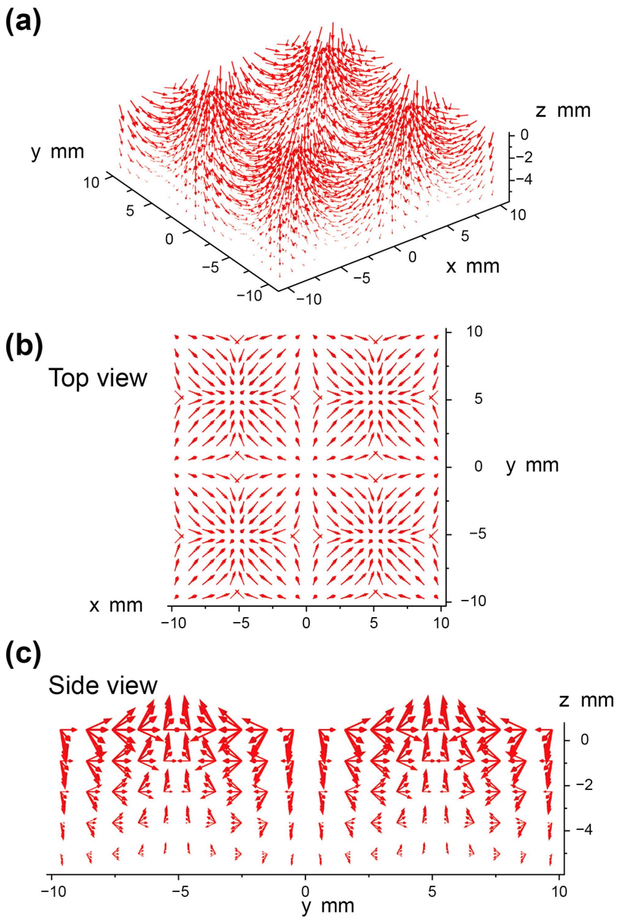
Figure 3a shows the 3D spatial distribution of the magnetic flux density vectors below the magnetic film, which is calculated by Equation (2). The magnetic flux density vectors present a saddle-shaped distribution with four peaks, whose top view and side view are shown in Figure 3b,c, respectively. In order to show a clearer distribution, the arrows’ lengths in the figure are treated with logarithmic calculations.
According to the magnetic field distribution formula (Equation (2)), we can have
This expression can be further expanded as
Simplifying the above expression, we obtain
Further simplification yields
By squaring both sides of the equation, we arrive at
which can be written as
At the same time, we can obtain
According to Equation (8), the equation can be expressed as
In order to eliminate the radical sign to simplify the equation, we can obtain
In the same way, we can obtain
In summary, we will obtain the relationship between the position (x, y, z) below the magnetic film and the triaxial magnetic flux density (Bx, By, Bz):
Equation (13) is the key to the achievement of 3D self-decoupling, where the three-axis coordinates of the magnetic film can be independently calculated according to the three-axis magnetic flux density. In order to facilitate calculation, we introduced three decoupling parameters (Rx, Ry, and Sz) that are linearly related to the displacements to calculate the triaxial displacement of the magnetic film, respectively:
where
Through this method, we can calculate the triaxial displacement of the ideally periodic centripetally magnetized film with infinite size (in x-y plane) according to the magnetic flux densities measured by the Hall sensor, demonstrating that the magnetic film has the ability to decouple triaxial displacement.
For isotropic materials, normal stress and shear stress are independent of each other, so the displacement in each direction can be directly linked to the force. Our magnetic tactile sensor senses the magnitude of the force indirectly by measuring the deformation of the elastomer substrate through the triaxial displacement of the magnetic film. Therefore, the mechanical properties and elastic response (force–displacement relationship) of the elastomer substrate still need to be measured after determining the magnetic–displacement relationship of the sensor. The applied force and the corresponding displacement of the elastic material are linearly correlated according to Hooke’s law. The external force F, with components , , and , can be calculated as
where S is the contact area, and γx, γy, ε, G, E, and h are the shear strain in the x direction, the shear strain in the y direction, normal strain, shear modulus, elastic modulus, and thickness of the elastomer substrate, respectively. For the isotropic silicone elastomer, , where v is the Poisson’s ratio of the material. According to Equation (14), and by introducing six compensation coefficients, we can obtain
where a1, a2, and a3 are compensation coefficients for elastic modulus and shear modulus, respectively, because the shear modulus and elastic modulus are affected by the combination of magnetic films, silicon elastomer, and adhesive. Meanwhile, there may be manufacturing defects in them. b1, b2, and b3 are used to compensate for the calibration deviation under different installation conditions. These compensation coefficients can be determined by force–displacement calibration.
However, even if the infinite period and size of this magnetic film can be avoided by reducing the operating range, its complex magnetization arrangement (the superposition of two orthometric sinusoids) prevents actual manufacturing. In this work, we achieved the fitting of this magnetization mode by splicing small magnets with distinct magnetization directions so that the prepared magnetic film will generate a 3D magnetic field distribution consistent with the ideal magnetization in a certain range.
2.2. Materials and Fabrication
The combination of SE 1700 base (DOWSIL, 11.71 wt%), SE 1700 catalyst (DOWSIL, 1.17 wt%), Ecoflex 00-30 Part B (Shanghai Zhixin Corp., Shanghai, China, 21.78 wt%), fumed silica nanoparticles (Aladdin Biochemistry Technology Corp., Shanghai, China, 2.72 wt%), and NdFeB microparticles (Jianghuai Ciye Corp., Huai’an, China, 62.62 wt%) made up the films’ magnetic materials. SE 1700 base and Ecoflex 00-30 Part B were mixed in a 1:2 volume ratio to achieve the suitable mechanical properties of the magnetic materials. The fumed silica nanoparticles were added to adjust the rheological properties of the materials. These components were thoroughly mixed by a planetary mixer (AR-100, THINKY Corp., Tokyo, Japan) at 2000 rpm for 2 min and then defoamed at 2000 rpm for 2 min. The fully mixed viscous magnetic paste was scraped into the mold (laser-cut aluminum sheet, thickness 1 mm) through a scraper blade, as shown in Figure 4a. After the magnetic paste had completely filled the cavities of the mold, the excess magnetic paste was removed, and then the aluminum sheet with magnetic paste was placed in the oven together and heated at 120 °C for 1.5 h (Figure 4b). The cured magnetic films were magnetized in a high-intensity magnetic field (4.0 T) generated by a high-current electromagnetic coil (JH12160). As shown in Figure 4c, the magnetic films and the aluminum sheet were vertically placed in the middle of the coil so that the magnetic films were parallel to the magnetizing magnetic field (Bm) to obtain the magnetization direction along the film’s plane, ensuring they had exactly the same magnetization strength and direction.
Through the above preparation method, three kinds of small magnetic films with the same magnetization intensity but different sizes were prepared, whose sizes are 3.3 mm 3.3 mm, 3.3 mm 1.7 mm, and 3.3 mm 0.85 mm, respectively. They were spliced together, as shown in Figure 5, where the largest square magnetic films were surrounded by the narrow magnetic films in a special orientation to simulate the magnetization superposition of two orthometric sinusoids. The part in the red dotted box at the center is a complete period of centripetal magnetization, which was surrounded by four half periods and four quarter periods to extend the applicable working range (x: −2 to 2 mm, y: −2 to 2 mm, z: 0–2 mm). The sizes of these small magnetic films were determined according to the consistency of the overall magnetic moments between the spliced magnetic film and the ideal magnetic film in half a period.
These magnetic films are bonded to the polyimide tape piece by piece to prevent misalignment caused by their mutual repulsion or attraction and finally spliced into a complete film, as shown in Figure 5. The spliced film was then placed at the bottom of a 3D-printed mold, which was filled with a kind of elastomer matrix that made the magnetic film embedded in the sensor’s elastomer substrate. The elastomer matrix was made from a 2:1 mass ratio of Ecoflex 00-30 and silicone oil, which was used to make the cured elastomer have a smaller elastic modulus, thus giving the sensor a relatively higher force-sensing sensitivity. They were stirred only through a glass rod and defoamed in a vacuum chamber, avoiding the delamination caused by the centrifuge. After being poured into the mold, they were placed together in a vacuum chamber to be defoamed for 5 min, followed by curing at 50 °C for 2 h. The Hall sensor was embedded in the elastomer substrate in the same way, after which the encapsulated magnetic films were bonded onto the elastomer substrate with silicone glue (DL-1020, 0.2~0.3 mL, evenly coating the contact surface). The tactile sensor was fabricated after the glue was completely cured at room temperature for 24 h.
3. Results and Discussion
3.1. Simulation and Verification of the Spliced Magnetic Film
The simulation of the magnetic flux density under the spliced magnetic film was carried out in COMSOL Multiphysics to verify the feasibility of the magnet splicing method, and all the relevant parameters of the simulation are listed in Table 1. According to the simulation result, the magnetic flux density distribution under the splicing magnetic film (Figure 6a–c) is consistent with that of the ideal magnetic film calculated through Equation (2) (Figure 6d–f). This result shows that it is practical to simulate the magnetic field generated by the ideal magnetization arrangement through the method of splicing magnets in a certain range.
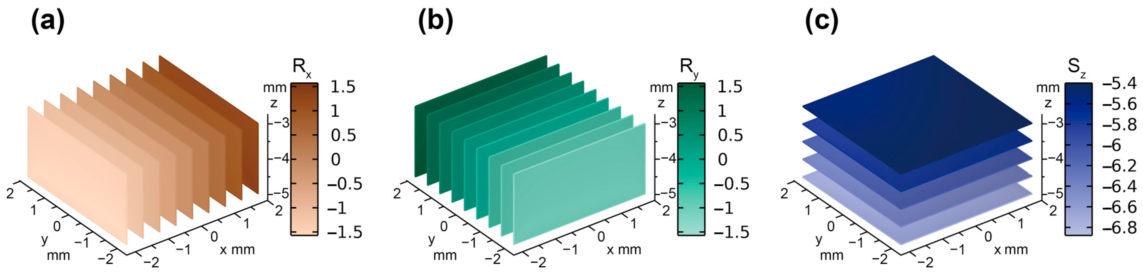
Based on the 3D magnetic flux density distribution of the spliced magnetic film obtained by the simulation, the distribution of decoupling parameters in the simulation could be calculated by Equation (15), as shown in Figure 7. The gradation of colors in the figure indicates the magnitude of the decoupling parameter values. As shown in Figure 7a, the uniformity of color in the y-z plane indicates that the decoupling parameter Rx is independent of the displacements in the y- and z-directions but only related to the displacement in the x-direction. Similar conclusions can be drawn for the decoupling parameters Ry (Figure 7b) and Sz (Figure 7c), which show that the spliced magnetic film has great decoupling performance.
3.2. Decoupling Performance in Experiment
The 3D magnetic field distribution below the spliced magnetic film could be accurately measured by fixing it on a 3D mobile platform (PMS-3, PowerScin, Shanghai, China) and driving it to perform three-axis displacements above the Hall sensor. The magnetic field data were recorded with a step length of 0.5 mm, according to which the distribution of decoupling parameters (Rx, Ry, and Sz) in 3D space can be calculated in the practical experiment, as shown in Figure 8.
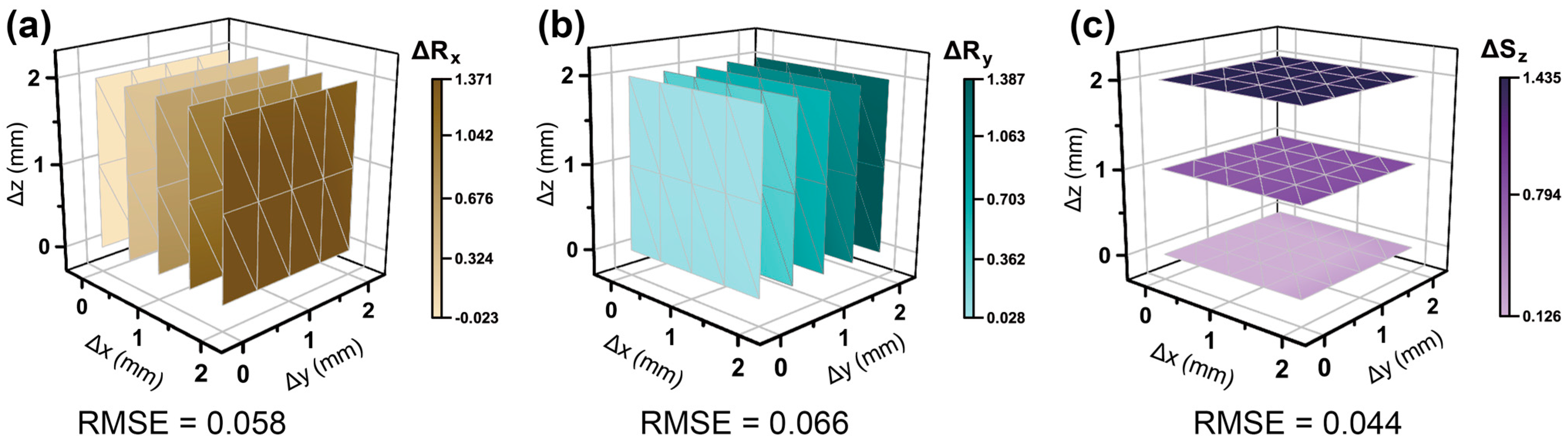
∆Rx is independently related to the displacement in the x-direction; that is, it changes with the displacement in the x-direction but remains constant when the displacement in the y- or z-direction changes (Figure 8a). ∆Ry (Figure 8b) and ∆Sz (Figure 8c) are also independently related to the displacement in the y-direction and the displacement in the z-direction, respectively, and remain constant as the displacements in the other two directions vary. For isotropic materials, the stresses in the three directions are independent of each other, so the displacement in any single direction can be directly linked to the force in that direction. Therefore, the relationships between the decoupling parameters and the external forces applied to the tactile sensor can be obtained directly from their relationships to the 3D displacements, which are much easier to clearly present. Moreover, in the process of splicing, part of the magnetic films is prone to position deviation, resulting in errors in the spatial distribution of decoupling parameters. The average root-mean-square errors (RMSEs) of ∆Rx, ∆Ry, and ∆Sz are 0.058, 0.066, and 0.044, respectively, indicating that the magnetic tactile sensor with the spliced film has good 3D decoupling performance over the shown operating range. In addition, the displacement resolution of the sensor can be obtained here: 0.015 mm in both shear and normal directions, which is mainly limited by the resolution of the 3D Hall sensor to perceive the magnetic flux density. Therefore, the improved performance of 3D Hall sensors will lead to enhanced force sensing performance of our sensors.
Compared with the decoupling parameter distribution results obtained by the simulation of the splicing model in Figure 7, the decoupling parameters obtained in the practical experiment also have good uniformity in their respective planes, as shown in Figure 8. Moreover, the values of the experimental decoupling parameters are more than 90 percent consistent with the simulation results. It can be said that the fabricated magnetic film matched the results expected from the simulation well. These results show that the decoupling performance of the spliced magnetic film verified by the simulation and experimental results is reliable, and the manufacturing error caused by the actual preparation of the magnetic film by the splicing method is in an acceptable range, which proves that the method has practical application value.
3.3. Force Sensing Experiment of the Tactile Sensor
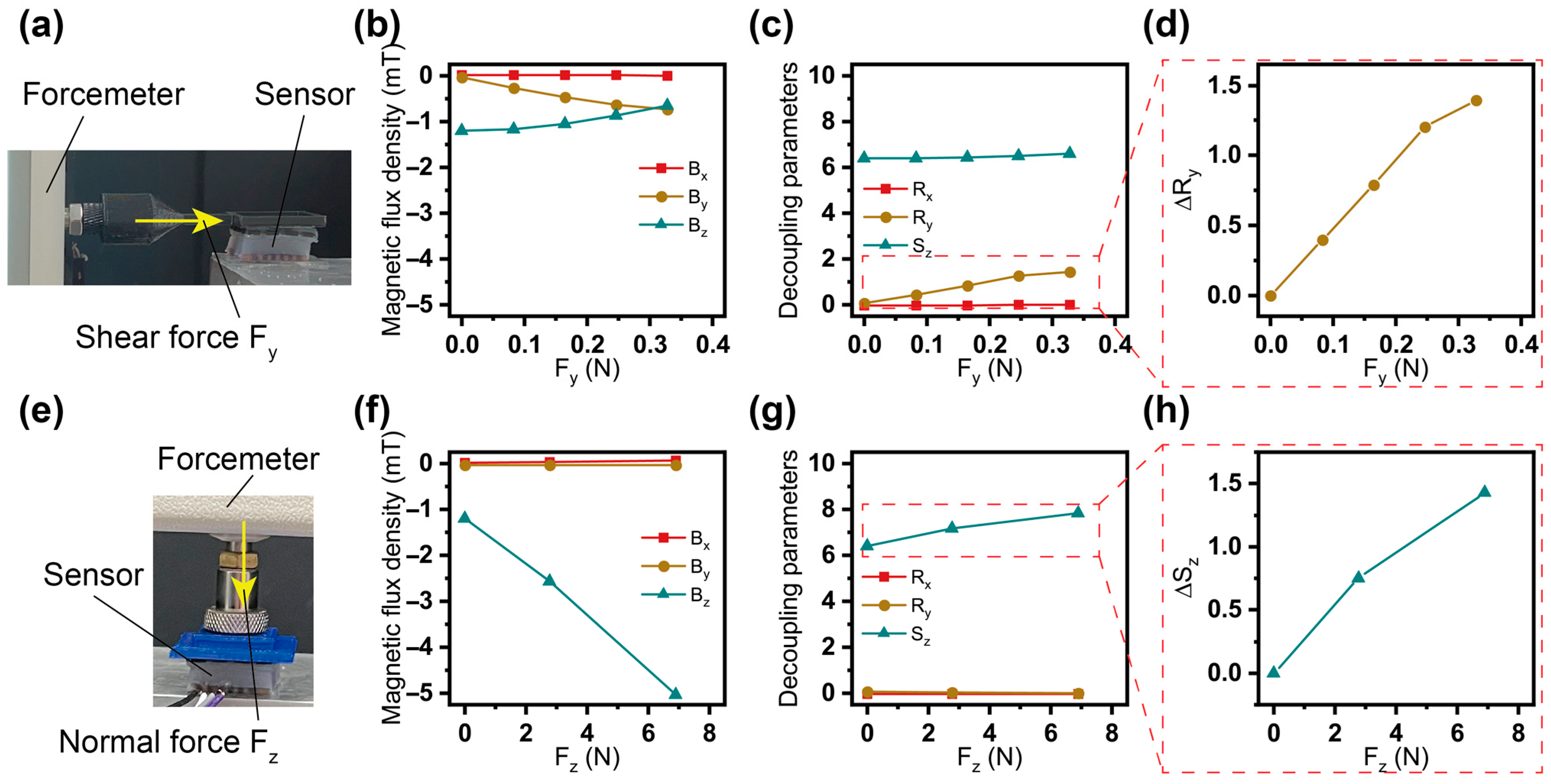
As shown in Figure 9a,e, the external forces were applied to the sensor through the forcemeter (Zhiqu, DS2-5N and 100N) fixed to the 3D mobile platform with a step size of 0.5 mm in the shear direction and 1 mm in the normal direction. In the process of applying force, according to the 3D magnetic flux density signals (Figure 9b,f) measured by the Hall sensor, the variations of the decoupling parameters (Figure 9c,g) could be calculated through Equation (15). It can be seen that when the shear force (or normal force) was applied, only the corresponding decoupling parameter Ry (or Sz) changed, while the other decoupling parameters remained constant. The readings of the forcemeters could be recorded to obtain the perception curves of the sensor to shear forces (Figure 9d) and normal forces (Figure 9h). Combined with the distribution of decoupling parameters in 3D space and the force perception curves of the tactile sensor, any force with an arbitrary direction and magnitude within the working range could be accurately sensed.
It is clear that this method also has obvious drawbacks; that is, the manufacturing process is quite cumbersome and inevitably produces manufacturing errors. At the same time, in the process of the force sensing experiment, the spliced magnetic films fixed together only by the cured Ecoflex 00-30 may shift their relative positions from the initial state when subjected to external normal forces and shear forces, thus changing the magnetic field distribution and bringing about errors. In addition, the bending of the magnetic film when the force is too large will also make the magnetic field distribution become different, resulting in a certain error. However, the results of the experiment show that the effects of these errors are not unacceptable. And most significantly, different from the method of folding the magnetic film in our previous work, the splicing method can make the magnetic film produce a more consistent flux density distribution in the 3D space with the ideal model so that the 3D self-decoupling can be realized in a close distance without any compensation and correction coefficient.
4. Conclusions
A magnet splicing method to simulate the special 3D magnetic field generated by a magnetic film with ideal centripetal magnetization was proposed, which could be used to realize the 3D force decoupling perception of the magnetic tactile sensor. The preparation methods of related materials and devices were explained in detail, and the feasibility and effectiveness of this splicing method have been fully verified by the simulation and experiment.
Considering future applications, greater optimization and improvement of the production process and design methodology are required to address the problems of manufacturing errors and binding tightness between the magnetic film and the elastomer. In addition, service life is also critical for sensor applications. Our sensors do not have any embedded wiring, so they have extremely high physical robustness and a long mechanical service life. However, high temperature, strong magnetic field, large mechanical stress, and oxidation will aggravate the demagnetization phenomenon of magnetic films, which should be avoided in the applications of magnetic-based sensors. For our sensor, the magnetic particles wrapped in the flexible matrix are difficult to oxidize, while the mechanical stress is also low due to the flat magnetic film and small external forces. Therefore, as long as strong magnetic and high-temperature environments are avoided, the service life of our sensor under normal use will essentially not be affected by the demagnetization phenomenon and is sufficient for applications.
In conclusion, the magnet splicing method proposed in this paper can make the practical magnetic film more similar to the proposed ideal model so that the tactile sensor with this magnetic film has excellent decoupling performance. This method carves out a new way for the practical application of 3D decoupling theory. Furthermore, realizing complex magnetization arrangements by splicing magnets also has great potential in the fields of magnetic sensors and magnetic actuators.
Author Contributions
Conceptualization, H.D. and C.Z.; Methodology, all authors; Software, H.D.; Validation, H.D., C.M. and Z.W.; Formal Analysis, all authors; Investigation, H.D.; Resources, P.Z.; Data Curation, H.D., C.M. and Z.W.; Writing—Original Draft Preparation, H.D.; Writing—Review and Editing, H.D., C.Z. and P.Z.; Supervision, C.Z.; Project Administration, P.Z. All authors have read and agreed to the published version of the manuscript.
Funding
This work was supported in part by the National Natural Science Foundation of China under Grant No. 52205424; in part by the National Key R&D Program of China under Grant No. 2022YFC2401903; in part by the “Pioneer” and “Leading Goose” R&D Program of Zhejiang Province under Grant No. 2022C01069; and in part by Zhejiang Provincial Natural Science Foundation of China under Grant No. LY23A020001.
Institutional Review Board Statement
Not applicable.
Informed Consent Statement
Not applicable.
Data Availability Statement
The data used to support the findings of this study are available from the corresponding author upon request.
Acknowledgments
The authors would like to thank Zhejiang University-University of Illinois at the Urbana-Champaign Institute in Haining for offering us the opportunity to cooperate.
Conflicts of Interest
The authors declare no conflicts of interest.
References
- Xie, Z.; Yuan, F.; Liu, J.; Tian, L.; Chen, B.; Fu, Z.; Mao, S.; Jin, T.; Wang, Y.; He, X.; et al. Octopus-inspired sensorized soft arm for environmental interaction. Sci. Robot. 2023, 8, eadh7852. [Google Scholar] [CrossRef] [PubMed]
- Yan, Y.; Hu, Z.; Yang, Z.; Yuan, W.; Song, C.; Pan, J.; Shen, Y. Soft magnetic skin for super-resolution tactile sensing with force self-decoupling. Sci. Robot. 2021, 6, eabc8801. [Google Scholar] [CrossRef] [PubMed]
- Liu, W.; Duo, Y.; Liu, J.; Yuan, F.; Li, L.; Li, L.; Wang, G.; Chen, B.; Wang, S.; Yang, H.; et al. Touchless interactive teaching of soft robots through flexible bimodal sensory interfaces. Nat. Commun. 2022, 13, 5030. [Google Scholar] [CrossRef] [PubMed]
- Li, J.; Jia, H.; Zhou, J.; Huang, X.; Xu, L.; Jia, S.; Gao, Z.; Yao, K.; Li, D.; Zhang, B.; et al. Thin, soft, wearable system for continuous wireless monitoring of artery blood pressure. Nat. Commun. 2023, 14, 5009. [Google Scholar] [CrossRef] [PubMed]
- Gao, J.; Fan, Y.; Zhang, Q.; Luo, L.; Hu, X.; Li, Y.; Song, J.; Jiang, H.; Gao, X.; Zheng, L.; et al. Ultra-Robust and Extensible Fibrous Mechanical Sensors for Wearable Smart Healthcare. Adv. Mater. 2022, 34, 2107511. [Google Scholar] [CrossRef] [PubMed]
- Tee, B.C.; Chortos, A.; Berndt, A.; Nguyen, A.K.; Tom, A.; McGuire, A.; Lin, Z.C.; Tien, K.; Bae, W.G.; Wang, H.; et al. A skin-inspired organic digital mechanoreceptor. Science 2015, 350, 313–316. [Google Scholar] [CrossRef]
- Wu, Y.; Liu, Y.; Zhou, Y.; Man, Q.; Hu, C.; Asghar, W.; Li, F.; Yu, Z.; Shang, J.; Liu, G.; et al. A skin-inspired tactile sensor for smart prosthetics. Sci. Robot. 2018, 3, eaat0429. [Google Scholar] [CrossRef]
- Johnson, K.O. The roles and functions of cutaneous mechanoreceptors. Curr. Opin. Neurobiol. 2001, 11, 455–461. [Google Scholar] [CrossRef]
- Abraira, V.E.; Ginty, D.D. The Sensory Neurons of Touch. Neuron 2013, 79, 618–639. [Google Scholar] [CrossRef]
- Wang, S.; Deng, W.; Yang, T.; Ao, Y.; Zhang, H.; Tian, G.; Deng, L.; Huang, H.; Huang, J.; Lan, B.; et al. Bioinspired MXene-Based Piezoresistive Sensor with Two-stage Enhancement for Motion Capture. Adv. Funct. Mater. 2023, 33, 2214503. [Google Scholar] [CrossRef]
- Sun, X.; Sun, J.; Li, T.; Zheng, S.; Wang, C.; Tan, W.; Zhang, J.; Liu, C.; Ma, T.; Qi, Z.; et al. Flexible Tactile Electronic Skin Sensor with 3D Force Detection Based on Porous CNTs/PDMS Nanocomposites. Nano-Micro Lett. 2019, 11, 57. [Google Scholar] [CrossRef] [PubMed]
- Zhang, J.; Yao, H.; Mo, J.; Chen, S.; Xie, Y.; Ma, S.; Chen, R.; Luo, T.; Ling, W.; Qin, L.; et al. Finger-inspired rigid-soft hybrid tactile sensor with superior sensitivity at high frequency. Nat. Commun. 2022, 13, 5076. [Google Scholar] [CrossRef] [PubMed]
- Zhou, P.; Zheng, Z.; Wang, B.; Guo, Y. Self-powered flexible piezoelectric sensors based on self-assembled 10 nm BaTiO3; nanocubes on glass fiber fabric. Nano Energy 2022, 99, 107400. [Google Scholar] [CrossRef]
- Bai, N.; Xue, Y.; Chen, S.; Shi, L.; Shi, J.; Zhang, Y.; Hou, X.; Cheng, Y.; Huang, K.; Wang, W.; et al. A robotic sensory system with high spatiotemporal resolution for texture recognition. Nat. Commun. 2023, 14, 7121. [Google Scholar] [CrossRef] [PubMed]
- Fu, C.; Tang, W.; Miao, Y.; Xu, A.; Nilghaz, A.; Xu, W.; Dong, K.; Su, B.; Xia, Z. Large-scalable fabrication of liquid metal-based double helix core-spun yarns for capacitive sensing, energy harvesting, and thermal management. Nano Energy 2023, 106, 108078. [Google Scholar] [CrossRef]
- Hou, X.; Zhang, L.; Su, Y.; Gao, G.; Liu, Y.; Na, Z.; Xu, Q.; Ding, T.; Xiao, L.; Li, L.; et al. A space crawling robotic bio-paw (SCRBP) enabled by triboelectric sensors for surface identification. Nano Energy 2023, 105, 108013. [Google Scholar] [CrossRef]
- Qu, X.; Liu, Z.; Tan, P.; Wang, C.; Liu, Y.; Feng, H.; Luo, D.; Li, Z.; Wang, Z.L. Artificial tactile perception smart finger for material identification based on triboelectric sensing. Sci. Adv. 2022, 8, eabq2521. [Google Scholar] [CrossRef]
- Wei, R.; He, J.; Ge, S.; Liu, H.; Ma, X.; Tao, J.; Cui, X.; Mo, X.; Li, Z.; Wang, C.; et al. Self-Powered All-Optical Tactile Sensing Platform for User-Interactive Interface. Adv. Mater. Technol. 2023, 8, 2200757. [Google Scholar] [CrossRef]
- Sferrazza, C.; D’Andrea, R. Sim-to-Real for High-Resolution Optical Tactile Sensing: From Images to Three-Dimensional Contact Force Distributions. Soft Robot. 2022, 9, 926–937. [Google Scholar] [CrossRef]
- Zhang, X.; Ai, J.; Ma, Z.; Du, Z.; Chen, D.; Zou, R.; Su, B. Magnetoelectric soft composites with a self-powered tactile sensing capacity. Nano Energy 2020, 69, 104391. [Google Scholar] [CrossRef]
- Ma, Z.; Ai, J.; Zhang, X.; Du, Z.; Wu, Z.; Wang, K.; Chen, D.; Su, B. Merkel’s Disks Bioinspired Self-Powered Flexible Magnetoelectric Sensors Toward the Robotic Arm’s Tactile Perceptual Functioning and Smart Learning. Adv. Intell. Syst. 2020, 2, 1900140. [Google Scholar] [CrossRef]
- Li, D.; Zhou, J.; Yao, K.; Liu, S.; He, J.; Su, J.; Qu, Q.; Gao, Y.; Song, Z.; Yiu, C.; et al. Touch IoT enabled by wireless self-sensing and haptic-reproducing electronic skin. Sci. Adv. 2022, 8, eade2450. [Google Scholar] [CrossRef] [PubMed]
- Le Signor, T.; Dupre, N.; Close, G.F. A Gradiometric Magnetic Force Sensor Immune to Stray Magnetic Fields for Robotic Hands and Grippers. IEEE Robot. Autom. Let. 2022, 7, 3070–3076. [Google Scholar] [CrossRef]
- Wang, H.; de Boer, G.; Kow, J.; Alazmani, A.; Ghajari, M.; Hewson, R.; Culmer, P. Design Methodology for Magnetic Field-Based Soft Tri-Axis Tactile Sensors. Sensors 2016, 16, 1356. [Google Scholar] [CrossRef] [PubMed]
- Hu, X.; Zhu, H.; Chen, R.; Hu, S.; Jia, Z.; Yu, H.; Qu, S. Design of 3D Magnetic Tactile Sensors with High Sensing Accuracy Guided by the Theoretical Model. Adv. Intell. Syst. 2023, 5, 2200291. [Google Scholar] [CrossRef]
- Zhang, C.; Li, X.; Jiang, L.; Tang, D.; Xu, H.; Zhao, P.; Fu, J.; Zhou, Q.; Chen, Y. 3D Printing of Functional Magnetic Materials: From Design to Applications. Adv. Funct. Mater. 2021, 31, 2102777. [Google Scholar] [CrossRef]
- Hu, Z.; Zhang, C.; Sun, H.; Dai, H.; Tang, D.; Hu, H.; Li, T.; Fu, J.; Zhao, P. A microstructure enhancement method for hard magnetic particle chains based on magnetic field oscillation sieve. Mater. Des. 2024, 237, 112588. [Google Scholar] [CrossRef]
- Hu, Z.; Zhang, C.; Sun, H.; Ma, X.; Zhao, P. Length manipulation of hard magnetic particle chains under rotating magnetic fields. Sens. Actuators A Phys. 2023, 361, 114562. [Google Scholar] [CrossRef]
- Kim, Y.; Yuk, H.; Zhao, R.; Chester, S.A.; Zhao, X. Printing ferromagnetic domains for untethered fast-transforming soft materials. Nature 2018, 558, 274–279. [Google Scholar] [CrossRef]
- Lin, D.; Yang, F.; Gong, D.; Li, R. Bio-inspired magnetic-driven folded diaphragm for biomimetic robot. Nat. Commun. 2023, 14, 163. [Google Scholar] [CrossRef]
- Dai, H.; Zhang, C.; Pan, C.; Hu, H.; Ji, K.; Sun, H.; Lyu, C.; Tang, D.; Li, T.; Fu, J.; et al. Split-Type Magnetic Soft Tactile Sensor with 3D Force Decoupling. Adv. Mater. 2023, 2310145. [Google Scholar] [CrossRef] [PubMed]
Figure 1.
Structure illustration of the magnetic tactile sensor.

Figure 2.
Ideal centripetal magnetization method.

Figure 3.
Diagram of the 3D configuration of magnetic flux density vectors below the magnetic film with the ideal centripetal magnetization. (a) Magnetic flux density vectors between the Hall sensor and the magnetic film (the arrows’ lengths are calculated logarithmically). (b) Top view of the magnetic flux density vector distribution (the arrows’ lengths are calculated logarithmically). (c) Side view of the magnetic flux density vector distribution (the arrows’ lengths are calculated logarithmically).

Figure 4.
Preparation method of magnetic films. (a) Scrape the magnetic paste into the mold through a scraper blade. (b) Cure the formed magnetic paste at 120 °C. (c) Magnetize the cured films in a magnetizing coil.
Figure 4.
Preparation method of magnetic films. (a) Scrape the magnetic paste into the mold through a scraper blade. (b) Cure the formed magnetic paste at 120 °C. (c) Magnetize the cured films in a magnetizing coil.

Figure 5.
Schematic diagram of spliced magnetic films. (The top view of the sensor).

Figure 6.
Comparison of the magnetic flux density distribution obtained from the simulation of the splicing model and the calculation of the ideal model. (a) Bx, (b) By, and (c) Bz obtained by the simulation of the splicing model. (d) Bx, (e) By, and (f) Bz obtained by the calculation of the ideal model.

Figure 7.
The decoupling parameter distribution obtained by the simulation of the splicing model. (a) The simulation distribution of Rx under the splicing model. (b) The simulation distribution of Ry under the splicing model. (c) The simulation distribution of Sz under the splicing model.
Figure 7.
The decoupling parameter distribution obtained by the simulation of the splicing model. (a) The simulation distribution of Rx under the splicing model. (b) The simulation distribution of Ry under the splicing model. (c) The simulation distribution of Sz under the splicing model.

Figure 8.
Spatial distribution of decoupling parameters. (a) Decoupling parameter ∆Rx under the triaxial displacement of the spliced magnetic film. (b) Decoupling parameter ∆Ry under the triaxial displacement of the spliced magnetic film. (c) Decoupling parameter ∆Sz under the triaxial displacement of the spliced magnetic film.

Figure 9.
Force sensing experiment of the tactile sensor. (a) Illustration of applying shear forces. (b) Three-dimensional magnetic flux density signals during the application of shear forces. (c) Changes in decoupling parameters during the application of shear forces. (d) Relationships between the shear force and decoupling parameter ∆Ry (or ∆Rx) of the sensor. (e) Illustration of applying normal forces. (f) Three-dimensional magnetic flux density signals during the application of normal forces. (g) Changes in decoupling parameters during the application of normal forces. (h) Relationships between the normal force and decoupling parameter ∆Sz of the sensor.


Table 1.
Parameters of magnetism for magnetic films and the range of study in simulation and calculation.
Table 1.
Parameters of magnetism for magnetic films and the range of study in simulation and calculation.
| Parameter | Splicing Model | Ideal Model |
|---|---|---|
| Remanence () | 0.12 (T) | 0.12 (T) |
| Wavelength () | 10 (mm) | 10 (mm) |
| Film size | 20 × 20 (mm) | Infinite |
| Thickness (d) | 1 (mm) | 1 (mm) |
| Range of study | x: −2~2, y: −2~2, z: −5~−3 (mm) | x: −2~2, y: −2~2, z: −5~−3 (mm) |
Disclaimer/Publisher’s Note: The statements, opinions and data contained in all publications are solely those of the individual author(s) and contributor(s) and not of MDPI and/or the editor(s). MDPI and/or the editor(s) disclaim responsibility for any injury to people or property resulting from any ideas, methods, instructions or products referred to in the content. |
© 2024 by the authors. Licensee MDPI, Basel, Switzerland. This article is an open access article distributed under the terms and conditions of the Creative Commons Attribution (CC BY) license (https://creativecommons.org/licenses/by/4.0/).
Share and Cite
MDPI and ACS Style
Dai, H.; Wu, Z.; Meng, C.; Zhang, C.; Zhao, P. A Magnet Splicing Method for Constructing a Three-Dimensional Self-Decoupled Magnetic Tactile Sensor. Magnetochemistry 2024, 10, 6. https://doi.org/10.3390/magnetochemistry10010006
AMA Style
Dai H, Wu Z, Meng C, Zhang C, Zhao P. A Magnet Splicing Method for Constructing a Three-Dimensional Self-Decoupled Magnetic Tactile Sensor. Magnetochemistry. 2024; 10(1):6. https://doi.org/10.3390/magnetochemistry10010006
Chicago/Turabian StyleDai, Huangzhe, Zheyan Wu, Chenxian Meng, Chengqian Zhang, and Peng Zhao. 2024. "A Magnet Splicing Method for Constructing a Three-Dimensional Self-Decoupled Magnetic Tactile Sensor" Magnetochemistry 10, no. 1: 6. https://doi.org/10.3390/magnetochemistry10010006
Note that from the first issue of 2016, this journal uses article numbers instead of page numbers. See further details here.