Article

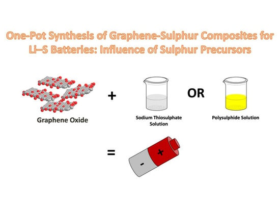
One-Pot Synthesis of Graphene-Sulfur Composites for Li-S Batteries: Influence of Sulfur Precursors

1
Division of Chemistry and Biological Chemistry, School of Physical and Mathematical Sciences, Nanyang Technological University, Singapore 637371, Singapore
2
Institute for Complex Materials, Leibniz Institute for Solid State and Materials Research (IFW), 01069 Dresden, Germany
3
Department of Chemistry, Universidad Nacional de Río Cuarto-CONICET, X5804ZAB Río Cuarto, Argentina
*
Authors to whom correspondence should be addressed.
Submission received: 30 November 2017 / Revised: 19 December 2017 / Accepted: 20 December 2017 / Published: 27 December 2017
(This article belongs to the Special Issue Functional Nanoporous Carbon-Based Materials)

Abstract

:
Lithium-sulfur (Li-S) batteries are postulated as next-generation electrochemical energy storage devices due to their increased storage capabilities. However, challenges persist from the polysulfide-shuttle effect at the cathode. Soluble sulfur-based species in the cathode cross over to the lithium anode through the separator leading to fading capacity with cycling. This has spurred continuous effort by the scientific community to develop novel cathodes where sulfur species can affix better. A conductive nanostructured graphene network is a suitable candidate that can serve as a scaffold for holding sulfur nanoparticles. Here, a one-pot synthesis of chemically reduced graphene oxide networks prepared from easily accessible graphene oxide is demonstrated. The solution-based method simply allows for impregnation of the graphene oxide network with sulfur nanoparticles through a careful manipulation of pH of the chemical environment. Two routes were chosen for the precipitation of such sulfur nanoparticles: firstly, the dissolution of sulfur in sodium hydroxide into polysulfides followed by acidification and secondly, the acidification of sodium thiosulfate from alkaline media into sulfur nanoparticles. Both graphene oxide materials from the two routes were treated with sodium borohydride to achieve conductive graphene. The second route, with the sulfur nanoparticles derived from the acidification of sodium thiosulfate with chemically reduced graphene oxide, demonstrated favorable electrochemical behavior, showing promise as electrode material for Li-S batteries.

Graphical Abstract

1. Introduction

In today’s world, there is a dearth in capacity to store renewable energy in the form of electricity [1,2]. Electrochemical energy storage systems serve to fulfil the shortcomings, having been used in hybrid vehicles, as backup energy storage as well as small mobile devices [3]. The bulk of the focus in commercial utilization for urban mobility devices has been on lithium-ion battery technology [4]. This application has greatly revolutionized people’s lifestyles, ranging from personal transport and their daily choices of how they use household goods, to small personal electronics [5]. However, new innovations are dearly needed for a paradigm change in energy storage due to these ever increasing demands.
Lithium ion technologies have been reliant on the usage of intercalation chemistry in metal oxides such as LiCoO2, Li (Ni, Mn, Co.) O2 and LiFePO4 [6], where capacities are typically less than 300 mAh·g−1. This capacity is insufficient to meet the specific energy requirements for electric vehicles and backup electrochemical storage devices for off-grid solutions and decentralized systems [1,2], to cope with the fluctuations of electricity from renewable sources [7].
Lithium-sulfur (Li-S) batteries are a plausible answer to the shortcomings in the energy equation [8]. A pure sulfur cathode offers a theoretical specific capacity of 1672 mAh·g−1 [9,10]. The combination of lithium and sulfur has a high theoretical energy capacity of 2600 Wh/kg [10,11], on the basis of the complete reaction of sulfur with lithium to form lithium sulfide (Li2S), a value that is up to five times higher than current lithium-ion batteries [12]. Notably, sulfur as a natural resource is cheap, environmentally friendly and abundant [13,14], itself being a by-product from fossil oil refinement, where it is typically produced in large quantities [15]. When the first discharge of Li-S batteries take place, elemental solid sulfur cathodes solubilize to intermediate polysulfide species such as (Li2S8, Li2S6 and Li2S4) and then becomes solid Li2S2 and Li2S. During the next charging cycle, these two species of Li2S2 and Li2S are converted back to S through soluble polysulfide intermediates again [9,10,11,14,16].
The main challenge with the Li-S system is that the dissolution to soluble polysulfides leads to the polysulfide shuttle effect. Namely, in the commonly used organic ether-based electrolyte, these polysulfide species continuously diffuse between both electrodes through the membrane separator. This leads to the deposition of S, Li2S2 and Li2S on the lithium anode, resulting in low Coulombic efficiency and rapid capacity fade in Li-S batteries and thus short lifetime [8,12]. Furthermore, the insulating sulfur requires intimate contact with the scaffold to guarantee an effective electron transport [17,18]. Most advocates of Li-S batteries are proponents of using sulfur nanoparticles to coat a conductive scaffold. Numerous carbon materials have been raised as possible candidates, such carbon nanospheres [19] and carbon from biological sources such as lignin [20]. Recent interests have been directed to nanostructured graphene materials due to their large surface area, availability of chemical groups that serve as anchors and high conductivity [17,18,21]. The possibility of manufacturing graphene in large quantities through its oxidized analogue of graphene oxide also presents itself as one of the most favorable candidates for commercialization [22,23]. Graphene oxide is also porous due to the highly oxidative preparation conditions [24] as well as the layered nature of the material that allows the trapping of sulfur nanoparticles [25].
In contemporary literature, several reports have used graphene oxide as a carbon scaffold to be impregnated with sulfur nanoparticles [17,18,21]. One of the first reports is by Nazar and co-workers, who utilized graphene oxide to wrap sulfur nanoparticles for the Li-S batteries in a one-pot synthesis [17]. However, the above report only makes use of the weak reducing power of polysulfide to restore conductivity in graphene oxide. In another work, with the utilization of solution environments, the ionic strength was carefully manipulated to allow the graphene oxide to wrap pre-synthesized sulfur nanoparticles to reduce the amount of dissolved polysulfide from escaping [21]. Mildly oxidized graphene oxide has also been used to endow oxygenated groups onto graphene that better anchor sulfur nanoparticles, while still maintaining its highly conductive nature [18]. This feature has been made possible with the separate synthesis of the nanoparticles and introduction of surfactants. To date, there has been no report of a one-pot synthesis of chemically reduced graphene oxide embedded with sulfur nanoparticles, with careful consideration of the solution environments and simultaneous purposeful chemical reduction step to allow a facile synthesis procedure to produce such nanocomposites with a coating of sulfur nanoparticles.
Here, we explore the one-pot synthesis of graphene-sulfur composites that allows a facile formation of sulfur nanoparticles trapped in the reduced graphene oxide nanostructure to be used towards Li-S batteries. Two routes of impregnating sulfur into the nanoarchitectonics of graphene are undertaken: (i) The dissolution of sulfur in sodium hydroxide [26,27,28] followed by acidification [17] and (ii) The acidification of sodium thiosulfate from alkaline environments [18,19], in order to introduce sulfur into the graphene network. In the present work, we study the one-pot synthesis, characterization and evaluation of materials from these two routes. The abovementioned variations have been the predominant methods for the synthesis of carbon-sulfur composite for Li-S batteries. However, there have been no comparative studies of these methods of synthesis for Li-S battery cathodes. We demonstrated the possibility of synthesizing reduced graphene oxide, which is impregnated with sulfur nanoparticles in a one-pot strategy and investigated the influence of the sulfur precursors for the construction of such nanocomposites.

2. Results and Discussion

A one-pot synthesis of graphene-sulfur composite was undertaken by a solution-based method. At first, graphene oxide is synthesized by a modified Hummer’s method to achieve few-layer graphene oxide sheets [29]. Two pathways were identified for the synthesis of graphene-sulfur composites. In the first pathway, sulfur is dissolved in sodium hydroxide solution [17,26,27,28] to form a polysulfide solution, before the addition of graphene oxide and eventual reduction with NaBH4 followed by acidification to form the material, and was labelled as GS1 (illustrated in Scheme 1A). For the second pathway, we conceptualized the reduction of graphene oxide in sodium hydroxide with NaBH4 before the sulfur precipitation from sodium thiosulfate [19], and will be henceforth referred to as GS2, by altering the alkaline environment to an acidic environment, impregnating sulfur into the graphene nanostructure (Scheme 1B). These two methods both involve the graphene oxide being subjected to reduction in sodium borohydride to achieve conductive few-layer sheets of chemically reduced graphene oxide [30,31,32]. As the final step, a work-up reaction with HCl was done to remove the remaining reactants of sulfur precursors and sodium borohydride, which also serves to increase the ionic strength of the environment, so that the graphene sheets can wrap around the sulfur nanoparticles [21]. Four different synthesized graphitic samples were examined. Namely, they are graphene oxide (GO), chemically reduced graphene oxide (CRGO) obtained using sodium borohydride, graphene-sulfur composite 1 (GS1) and graphene-sulfur composite 2 (GS2). GO and CRGO were used as control experiments to contrast the physical and chemical changes in compositions of the materials. Both the graphene-sulfur composites (GS1, GS2) were analyzed with carrier gas hot extraction method to quantify the sulfur content. The raw sulfur content was found to be 85.9 wt % for GS1 and 84.1 wt % for GS2 for the carbonaceous graphene scaffolds. For coating of the material into cathodes as coin-cell batteries, additives of carbon black and binder were introduced.
The cycling performance of the graphene-sulfur composite GS1, synthesized by the polysulfide route, is illustrated in Figure 1A. The current rate (C rate) was calculated based on the theoretical specific capacity of sulfur, where a 1 C rate corresponded to a current density of 1672 mA·g−1. During the first discharge, it demonstrates a capacity of 810 mAh·g−1. There was a loss of charge capacity in the third cycle to 141 mAh·g−1 and the Coulombic efficiency of the battery drops to 66% at the fourth cycle. Although the Coulombic efficiency fluctuates significantly, it reaches stability from 10th cycle onwards. It was noted that the GS1 material shows poor retention of the charge. The discharge capacity drops to 78 mAh·g−1 after cycling to the fourth cycle where the capacity of GS1 remains relatively constant at ~100 mAh·g−1. This observation is attributed to the polysulfide shuttle effect leading to the rapid loss of active material and thus specific capacity [11]. The rapid dissolution of the sulfur has led to rapid capacity loss within the first 4 charging/discharging cycles. Due to the relative ease of converse dissolution of sulfur particles fabricated from such a synthetic route, they easily transform into polysulfides and escape into the organic solvent [33,34]. Formation of polysulfides from the dissolution of sulfur in sodium hydroxide followed by acidification to form graphene-sulfur composites may not be a suitable route for synthesis of composites for use in Li-S batteries due to low Coulombic efficiency and rapid capacity fading. The unsuitability was also reflected in the morphology as large particles of sulfur are found on the surface of the graphene oxide scaffold (Refer to Figure 2C). These large sulfur particles lead to the incomplete lithiation during charge/discharge, due to inaccessibility to the inner core of the sulfur particle, culminating it to considerably fall short of its theoretical capacity [35]. The large exposed surfaces of the sulfur particles, also makes the dissolution easier, leading to polysulfide shuttle effect [18].
The cycling performance of graphene composite GS2, prepared by the thiosulfate route, was evaluated at current rate of C/10 and is shown in Figure 1B. During the 1st charge/discharge cycle, the Li-S battery shows a high discharge capacity of 1200 mAh·g−1, which is considerably higher that what was observed for GS1. Moreover, the initial capacity loss is to a markedly lesser extent as compared to GS1. At the fourth cycle, the battery shows a discharging capacity of 849 mAh·g−1, a value that is significantly higher than the 78 mAh·g−1 as examined in GS1. After the 4th cycle, the electrochemistry and in-turn the specific capacity is rather stable as illustrated in Figure 1C. Particularly, the sulfur-dissolution to polysulfide plateau during discharge (at ~2.35 V) as well as during charging at ~2.21 V. This is due to the polysulfide dissolution being considerably reduced during the initial 4 cycles. Upon prolonged cycling to the 50th cycle, the GS2-based Li-S battery still shows a capacity of 765 mAh·g−1. The battery also demonstrated high Coulombic efficiency of ~95% throughout the cycles, while retaining high capacity at the 50th cycle, in contrast to the battery with GS1-based electrode. Thus, the high specific capacity as well as the high Coulombic efficiency of 95% and the ability for the retention of the capacity demonstrates that this battery shows promise as an electrochemical storage device.
Polarization between charge and discharge cycles was derived at 50% depth of discharge for 10th, 20th, 30th, 40th and 50th cycles (Supporting information: Table S1) and an average polarization ΔE = 0.212 V was obtained (Figure 1D). In comparison to conventional Li-S batteries, where ΔE values of 0.25–0.3 V have been reported [9,14], a lower average polarization for GS2-based battery is a sign of faster reaction kinetics [9]. With the polarization of the GS2-based Li-S cell being shifted to lower potentials, it also demonstrates the conductive contact of the carbon scaffold with the sulfur particles [14].
To achieve better understanding between the electrochemical performance and the composite structure, the material was further characterized by scanning electron microscopy, X-ray powder diffraction and Raman spectroscopy. Furthermore, the cells were electrochemically evaluated by using long-term charging/discharging profiles and the practical use of such Li-S battery was simulated by alteration of the charging/discharging current at high current densities.
Figure 2A shows the secondary electron (SE) image of graphene oxide from scanning electron microscopy (SEM) and is indicative that the graphene oxide has been subjected to the aggressive oxidation of the graphite in acidic media by potassium permanganate [36]. The sheets of graphene oxide have been extensively damaged, leading the edges to be folded and parts of them appear to be crumpled. As such, the graphene oxide has increased interlayer spacing which enables it to be used for the next stage for exfoliation under ultrasonic excitation and later chemical reduction by sodium borohydride. As displayed in the SE image in Figure 2B, smaller particles of reduced graphene oxide are formed as is expected after ultrasonication and reduction of graphene oxide upon treatment with sodium borohydride [32]. The sheets of reduced graphene oxide are crumpled and have randomly stacked after drying during sample preparation for SEM. The polysulfide route afforded reduced graphene oxide-sulfur composite 1 (GS1) that contains large sulfur particles in Figure 2C. On the other hand, reduced graphene oxide impregnated with sulfur from the sodium thiosulfate precursor (GS2) is shown in Figure 2D. Elemental mapping was carried out using Scanning Electron Microscope coupled to Elemental Dispersive X-ray Spectroscopy (SEM-EDXS). In the control experiment, where no sulfur was introduced into the chemically reduced graphene oxide (CRGO) in Figure 2E, small amount of sulfur was found in the SEM-EDXS. Elemental mapping using SEM-EDXS was also done on GS2 and given therein in Figure 2F, shows the uniform coating of sulfur on the crumpled graphene sheets (GS2). A strong charging effect was also observed due to the presence of sulfur is observed, demonstrating the successful coating of sulfur on the reduced graphene oxide sheets. This is of particular advantage for electrode preparation as well as during cell cycling for lithiation, where the crumpled sheets serve as a scaffold to envelope the coated sulfur layer. The sulfur content corresponds well with the carrier gas hot extraction method, where a sulfur content of 84 wt % was found. It is noted that this is a significantly high loading as compared to what has been reported in literature [18].
X-ray photoelectron spectroscopy (XPS) is a useful technique to evaluate the surface elemental composition and chemical states of the material. During preliminary investigation, survey XPS were obtained that give a ready overview of the present elements. The spectra markedly indicate the decreasing oxygen content of the graphitic materials from GO (37 at. %) to CRGO (16 at. %) and GS2 (16 at. %). For a detailed investigation, high-resolution spectra of the C 1s band region of the three carbon materials (GO, CRGO and GS2) were taken and are shown in Figure 3. Four individual Gaussian curves are fitted into each spectrum, which originate from the presence of the sp2 carbon bonds, hydroxyl, carbonyl and carboxylic acid groups respectively [30,37]. Figure 3A depicts the high resolution C 1s spectra for graphite oxide (GO). In addition to the carbon functionality of the sp2 C=C species at 284.5 eV, the strong peaks of the oxygenated carbon functionalities of C–OH at 286.5 eV, C=O at 288.4 eV and C–OOH at 291.4 eV are indicative that the strong oxidizing condition of potassium permanganate in acidic conditions has introduced oxygen moieties into the graphene layers (Supporting information: Table S2) [29]. There is a significant decrease of the C–OH peak area, where a reduction of the C–OH constituent from 38 at. % in GO in Figure 3A to 20 at. % in CRGO at signal position of 285.7 eV is noticed, as represented in Figure 3B. Upon introduction of NaBH4 as the reducing agent, significant removal of oxygenated groups occurs, suggesting a restoration of the sp2 backbone in chemically reduced graphene oxide [30,31]. The large decrease of the C–OH peak area is also indicative of the successful reduction of the graphene oxide scaffold.
As depicted in Figure 3C, the C–OH species peak constitutes 19 area % of the overall surface group composition. The GS2 composite demonstrated the highest amount of reduction as it has been treated with both NaBH4 and sodium thiosulfate, which is also a chemical reductant [38,39]. The overall reduction in oxygen content in the high-resolution O 1s spectra band also corroborates a similar trend as the survey scan, where the oxygen content decreases from 38 at. % in GO to 16 and 16 at. % in CRGO and GS2, respectively (Supporting information: Table S3). High resolution S 2p spectra was also measured for the three carbon materials, GO, CRGO and GS2. Notably, sulfur moieties are found in all three samples. While sulfonated groups are present in GO due to the oxidizing conditions in sulfuric acid [11] and sulfur moieties are lowest in CRGO, sulfur species of the terminal/bridging kind [40] (typical for elemental sulfur) are found as the most abundant group in GS2 (Supporting information: Table S4 and Figure S1). This observation confirms the successful introduction of elemental sulfur into the reduced graphene oxide network.
X-ray diffraction studies were carried out to investigate the chemical transformations of these materials and the influence on the structure of individual components. The XRD patterns of graphite, graphene oxide (GO) and chemically reduced graphene oxide (CRGO) are compiled in Figure 4A. For graphite, a sharp reflection is found at 26.7° which conforms to the 002 reflection of graphitic carbon [17]. Upon oxidation to graphene oxide, this reflection disappears and a very broad reflection at 9.7° emerges. This behavior is due to changes of the interlayer spacing of the graphite upon extensive oxidation of the graphite lattice in acidic media with potassium permanganate [41]. Upon chemical reduction, this reflection disappeared and the reflection at 22.9° appears which is indicative of the successful chemical reduction and removal of oxygenated groups, with some reorganization of a few-layer sheets of graphene [31]. XRD data for the graphene-sulfur composite GS2 was analyzed through the Rietveld method using α-sulfur with space group Fddd [42] as shown in Figure 4B (RBragg = 6.12). Since the exact structure model for CRGO is not available, a Le Bail-like treatment of a hexagonal P63/mmc graphitic phase was added to the refinement (Figure 4B). The details of the Rietveld analysis and the refined lattice parameters for both phases are given in the supplementary information (Table S5). In order to have a deeper understanding of the defects that were introduced during the course of chemical functionalization, a Raman spectroscopy study was undertaken.
Raman spectroscopy is useful for measuring the density of defects present in the carbon materials: the D band at about 1350 cm−1 originates from structural disorder and sp3-like defects in the backbone, and the G band at about 1580 cm−1 originates from sp2-hybridised carbon vibrations [30,32]. An analysis of the ratio of the intensities of the D band to the G band (ID/IG) can be used to examine the extent of defects in graphene after reduction [30]. The Raman spectra for graphite, GO, CRGO, GS2 and elemental sulfur (S) are displayed in Figure 5A. An estimation of the crystallite size (La) is derived from the following equation:
L a = ( 2.4 × 10 10 ) × λ 4 × I G I D
based on the ratio of the intensity of the G band (IG), intensity of D (ID) band and wavelength of the laser ( λ ) [43]. Graphitic crystallite sizes are 3.4, 16.6, 19.5 and 22.1 nm for graphite, GO, CRGO and GS2, respectively. This observation is a clear evidence for the disorder introduced into the graphitic parent material due to chemical treatments. Graphite has a layered sp2-hybridised structure leading to a low ID/IG ratio of 0.17, which fits to the reported value in literature [36]. Upon extensive oxidation of graphite, the GO shows an ID/IG ratio of 0.86, which is a result of defects due to oxidation and incorporation of oxygenated groups such as hydroxyl, epoxyl, carbonyl and carboxylic groups [32]. Upon ultrasonication and chemical reduction of GO, the CRGO shows an increased ID/IG ratio of 1.01. This increase in the ratio is indicative of the reduced sp2 lattice size of graphenes after reduction as reported previously [32]. Although the reduction of graphene oxide results in recovery of the graphene backbone, however, it is concentrated to small graphitic regions. For the chemical reduction with sodium borohydride, a decrease in the size of the sp2 domains and, simultaneously, an increase of their quantity all over the material has been proposed which results in an enhanced electrical conductivity [32]. This behavior eventually leads to a larger ID/IG ratio. Further increase in the ID/IG ratio was observed for GS2, due to a higher amount of the sulfur heteroatoms introduced into the graphitic sheets, leading to an increase in the ID/IG ratio to 1.15 [41]. The characteristic Raman spectra of the sulfur was observed in GS2 composite, bearing the specific Raman characteristic signals from the elemental sulfur [19,44] as observed in Figure 5B and further supports the XRD data (Figure 4A). Typically, the intense fingerprint signals are at 151, 216 and 410 cm−1, corresponding to the signals of elemental sulfur [44]. Band broadening was also noted in the D band in Figure 5A due to possibly underlying signals at 1437 and 1477 cm−1, as found in other sulfur infused carbon networks [45,46]. These signals are attributed to the disorder induced by sulfur heteroatom substitution and symmetry breaking defects in the sp2 carbon graphene planes with different surrounding chemical environments [47,48]. The fingerprint sulfur signals and the band broadening event in the D band are indicators that sulfur has been successfully integrated into the graphene structure.
In Figure 6A, the cyclic voltammograms of the cathode material are shown with a potential window of 1.8 ≤ U ≤ 2.6 V at a scan rate of 0.2 mV·s−1. Two separate cathodic signals were observed at 2.28 and 2.04 V. The signal at 2.28 V corresponds to the reduction of sulfur to higher order polysulfides (Li2Sx, 4 ≤ x ≤ 8), while the signal at 2.04 V corresponds to the reduction of these polysulfides to lower-ordered ones (Li2Sx, 2 ≤ x ≤ 4) [11,18]. In the anodic electrochemical oxidation, two separated anodic signals were observed at 2.34 and 2.42 V. These two signals correspond to the oxidation of lithium sulfides into sulfur and polysulfides, respectively [11,18]. The sulfur electrochemistry from the second to third cycle shows good cycling reversibility, with the peak current and the integrated area of the cathodic/anodic signals being almost equivalent.
The specific capacity of the Li-S battery using the GS2 nanocomposite was examined at different charging rates. In Figure 6B, the 10th cycle of all charging/discharging curves are displayed in order to illustrate the capability to be used at low and high current densities at different charging and discharging rates. The discharging curves exhibit sequential steps. This is due to the 1st step (~2.3 V) according to the conversion of sulfur to long chain polysulfides (Li2Sx, 4 ≤ x ≤ 8) and the subsequent step (~2.1 V) to cut long chain polysulfides into shorter chains (Li2Sx, 2 ≤ x ≤ 4) [10]. It should be noted that the rate of charging process controls the battery capacity performance fundamentally [18]. Four individual batteries were tested with different charge rates: C/10, C/5, C/2 and C. At a discharging rate of C/10, the specific capacity reaches 805 mAh·g−1 at the 10th cycle. Similarly, progressing to higher discharging rates of C/5, C/2 and C, the specific capacities decrease to 660, 541 and 257 mAh·g−1 at the 10th cycle, respectively. The decrease in capacities is reasoned in overpotentials due to the chemical composition of the electrodes and the resistance of the double layer during the high charging rates [49].
We evaluated the capacity of the Li-S battery with the GS2 composite for long-term charging/discharging at a relatively high rate of C/2 and its corresponding efficiency and is shown in Figure 6C. In the initial first cycle, the battery achieves a capacity of 819 mAh·g−1. Towards the 10th cycle, the capacity of the battery reaches 541 mAh·g−1. From that point on, the battery shows high stability with a Coulombic efficiency of ~96% per cycle, which remains at 504 mAh·g−1 at the 100th cycle. As observed in Figure 6C, after the 30th cycle, the charge and discharge capacities slightly increase with prolonged cycling, while the Coulombic efficiency remains relatively constant until the 100th cycle.
To demonstrate the application of such a battery, we evaluated such a Li-S battery performance at different charging rates and its corresponding efficiency, and the data are displayed in Figure 6D. In the first cycle, the battery shows a capacity of 975 mAh·g−1 at a current rate of C/10. Subsequently, the current rate is changed to C/5 in the 9th cycle, where a capacity of 719 mAh·g−1 is observed. The current rate is again increased to C/2 in the 20th cycle, where the capacity reaches 578 mAh·g−1. At the end of the charge/discharge cycling at the 35th cycle, the Coulombic efficiency remains at ~92%. A high current of 1.0 C is then imposed, where a steady capacity of 278 mAh·g−1 is maintained from the 37th to the 79th cycle. Meanwhile, the Coulombic efficiency is maintained at ~93%. The current rate is decreased back to C/10, where a capacity of 675 mAh·g−1 is reached at the 81st cycle. Despite the long-term charging/discharging curve, an efficiency of ~78% is still observed at the end of the 84th cycle.
Effect of cycling rates are additionally presented in Figure 6D. There is a clear difference between charging and discharging capacities during the initial C/10 rate. Apart from the expected decrease in capacity as the cycle rate is increased, the difference between the charge and discharge capacities reduce as rate is increased. This behavior is suggestive that chemistry is kinetically controlled, especially the polysulfide shuttling [50]. Higher C rates reduce the time for side reactions, in particular polysulfide formation and dissolution during charging and discharging, thereby allowing for a higher Coulombic efficiency. Another aspect, which should be noted, is that when the C rate is changed, it takes a few cycles for the kinetics to stabilize. This behavior is clearly visible when the C rate changes from C/2 to C at the 35th cycle. In this case, the discharge capacity is stable after 1–2 cycles, whereas the charge capacity stabilized only after 5–6 cycles. It may be understood that the kinetics of polysulfide dissolution and shuttle effect during charging are slower as compared to that during discharging. Therefore, it takes some more time before the equilibrium is reached [35,51]. Thus, tests regarding the rate capability may also shed light on the intrinsic chemistry of the cell, particularly in the case of Li-S batteries.
A one-pot synthesis of graphene oxide using sodium thiosulfate as the sulfur precursor (GS2) is superior to the case of graphene oxide prepared using the sulfur precursor originating from the dissolution of sulfur in sodium hydroxide (GS1). Different mechanisms to the formation of sulfur have occurred in the respective polysulfide (GS1) and thiosulfate (GS2) routes during impregnation of the reduced graphene oxide framework. This is due to the contrasting intermediates that are formed through polysulfides [52,53] and thiosulfates [52,54]. In GS1, the gradual acidification of polysulfides lead to the formation of long-chained polysulfanes, which decompose readily in the excess alkaline surrounding environment to form sulfur [52]. The polysulfanes are hydrophobic, and this precipitates to the formation and agglomeration of sulfur in an aqueous environment as they decompose. However, on the other hand, the thiosulfate route leads to the formation of polysulfane sulfonates, which are amphiphilic [52,54], culminating in possibly greater interactions with the reduced graphene oxide. In addition, residual oxygenated groups, such as hydroxyl and carboxylic moieties on the reduced graphene oxide in GS2, can serve as anchor points that interact with the sulfonate groups [55,56]. These interactions are much weaker in polysulfides, due to the lower electronegativity of sulfur [57]. Consequently, the greater interactions lead to the uniformed coating of GS2, unlike the large particles observed in GS1, as depicted in Figure 2. As a result, GS2 demonstrated superior charge/discharge capabilities with uniform electrochemical access to the coated sulfur material on graphene oxide. Due considerations, such as the coarsening effect of sulfur leading to larger particles [58], the interactions of sulfur-containing intermediates with the media [59,60,61,62] and interactions with the scaffold should be considered, allowing us to design a better scaffold for the cathode in lithium-sulfur batteries.
It is elucidated that the polysulfide shuttle effect has led to the overall deterioration of capacity and loss in Coulombic efficiency, along similar lines to what has been reported earlier [11]. GS2, studied in this work are more efficient than GS1 towards entrapping the polysulfides in the graphene scaffold. However, it is clear that the there is a significant effect of synthesis route on the nature of the material and cell performance, as GS2 performs considerably better than GS1. GS2 shows promise to be further developed as a stable electrode material for Li-S batteries, where alternative approach for inhibiting the polysulfide shuttle effect have proved to be quite successful, such as functional separators [11]. New alterations to the current synthesis method or to the graphene template itself, such as the introduction of doping agents, may serve to reduce such effect in loss of electrochemical performance [10].

3. Materials and Methods

3.1. Materials

Sulfuric acid (95–98%), hydrochloric acid (37%), N-methyl-2-pyrrolidone (NMP, 99 wt %), 1,3-dioxolane (DOL, 99.8 wt %), 1,2-dimethoxyethane (DME, 99.5 wt %), sodium nitrate, elemental sulfur and sodium thiosulfate were purchased from Sigma-Aldrich (Darmstadt, Germany). Hydrogen peroxide (30%), sodium hydroxide pellets, LiNO3 and sodium borohydride were purchased from Merck (Darmstadt, Germany). Graphite (KS6L; AE-102 L) and Super P carbon (SPC) were purchased from TIMCAL (Bodio, Switzerland). Polyvinylidene difluoride (PVDF, Solef 21216) was purchased from Solvay (Bruxelles, Belgium). Potassium permanganate was purchased from J.T. Baker (Schwerte, Germany). Lithium bis (trifluoromethylsulfonyl) imide salt (LiN·(CF3SO2)2, LiTFSI) was purchased from BASF (Independence, OH, USA). Milli-Q water (resistivity: 18.2 MΩ cm at 25 °C) was used throughout the experiments. All chemicals were used as received except LiTFSI and LiNO3, which were dried at 100 °C under vacuum prior to use.

3.2. Synthesis of Graphene Oxide (GO)

Graphene oxide was prepared using a modified Hummer’s method. In a typical synthetic procedure, graphite (1.5 g) was stirred with sulfuric acid (69.0 mL, 95–98%) for 20 min at 0 °C prior to the addition of NaNO3 (1.5 g) in portions. The mixture was left to stir for 1 h. KMnO4 (9 g) was then added in portions at 0 °C. The mixture was subsequently heated to 35 °C for 1 h. Water (120 mL) was then added into the mixture, which was heated afterwards to 90 °C. The temperature was maintained at 90 °C for 30 min. Additional water (300 mL) was added into the mixture. This was followed by a slow addition of H2O2 (30%, ca. 30 mL). The solid was subsequently centrifuged and washed with a copious amount of water until a neutral pH was obtained. The materials were kept in the oven at 60 °C for five days prior to usage.

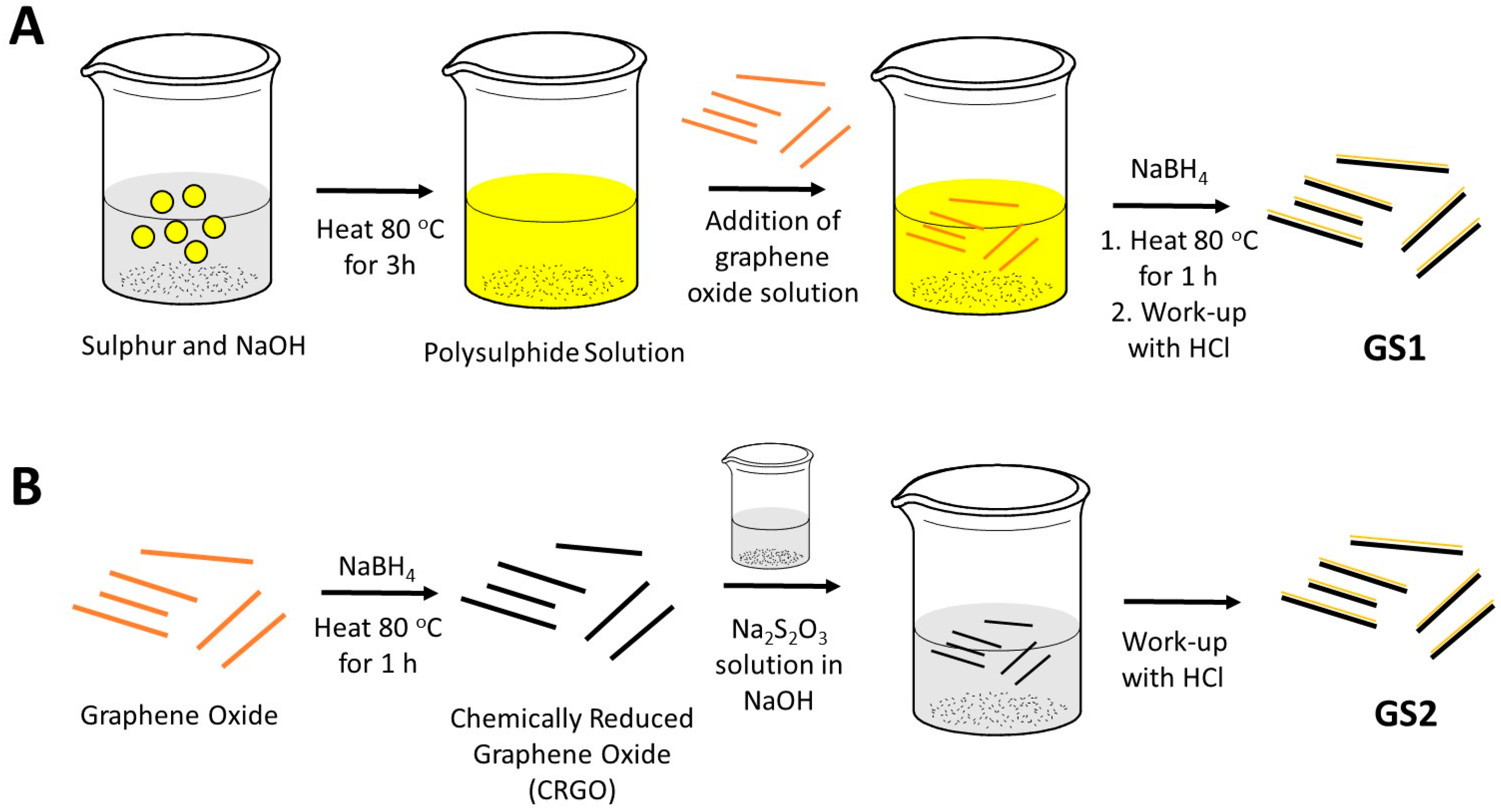
3.3. Synthesis of Graphene-Sulfur Composite by Dissolution of Sulfur in Sodium Hydroxide (GS1)

Graphene oxide (0.1 g) was sonicated for 1 h in 20 mL of deionized water. Subsequently, NaOH (0.8 g) was dissolved in the graphene oxide solution by sonicating for another 1 h. Separately, in another round bottomed flask, sulfur (1.5 g) was suspended in 1 M NaOH (100 mL) by sonication for 1 h. The solutions were mixed and heated at 80 °C for 3 h, where the sulfur dissolved to form a dark yellow solution in the presence of graphene oxide. To reduce the graphene oxide, a solution of NaBH4 (1.6 g) dissolved in 1 M NaOH (5 mL) was used. The NaBH4 solution was added dropwise to the graphene oxide-sulfur mixture and heated at 80 °C for 1 h. 7 wt % HCl (70 mL) was then added to terminate the reaction and to allow the formation of sulfur under vigorous stirring. Additionally, the solution was heated and stirred at 80 °C for 1 h and afterwards it was allowed to cool with stirring for 1 h. The product was washed with H2O and centrifuged until a neutral pH of the liquid phase was reached. The resulting material was dried overnight at 60 °C.

3.4. Synthesis of Graphene-Sulfur Composite by A Sodium Thiosulfate Route (GS2)

Graphene oxide (0.1 g) was sonicated for 1 h in deionized water (20 mL) to form a solution of graphene oxide. Subsequently, NaOH (4 g) was added to the graphene oxide solution which was sonicated for another 1 h. To reduce the graphene oxide, a solution of NaBH4 (1.6 g) dissolved in 1 M NaOH (5 mL) was used. The NaBH4 solution was added dropwise to the graphene oxide mixture and heated at 80 °C with stirring for 1 h. The sulfur precursor Na2S2O3 (2.25 g) was then added and stirred for 1 h, while the heat bath was maintained at 80 °C. 7 wt % HCl (70 mL) was then added to terminate the reaction and to allow the formation of sulfur under vigorous stirring. The solution was heated at 80 °C for 2 h with stirring. The solution was then allowed to cool down with stirring for 1 h. The product was washed with water and centrifuged until a neutral supernatant was reached. The residue was dried overnight in an oven at 60 °C.

3.5. Composite Cathodes Fabrication

The composite cathodes were prepared by shaker-milling the graphene-sulfur composite, Super P carbon and PVDF-HFP with an 80:10:10 wt % in NMP. The obtained viscous slurry was coated onto an aluminum foil current collector by the doctor blade method and dried at 60 °C for 20 h in an oven under air. From the coated foil electrodes were cut as circular disks of 12 mm. Sulfur content of the electrode is at 1.43 mg cm−2 for GS1 and 0.92 mg cm−2 for GS2 respectively.

3.6. Preparation of Li-S Cells

CR2025-type stainless steel coin cells were assembled in an Ar-filled glove box. The electrolyte solution was 20 µL of 1 M LiTFSI salt in a mixed solvent of 1,3-dioxolane and 1,2-dimethoxyethane (1:1 by volume), with 0.25 M LiNO3 as additive. LiNO3 was added to ensure the protection of the lithium anode from possible electrolyte depletion. Lithium metal foil (Chempur, Karlsruhe, Germany, diameter 13 mm, thickness 250 μm) was used as anode material and reference electrode. A commercial microporous polypropylene separator (Celgard 2500, Celgard LLC, Charlotte, NC, USA, diameter 16 mm) was used as pristine separator. The separator was placed between the graphene-sulfur composite cathode and the lithium anode.

3.7. Electrochemical Measurements

The cells were cycled at room temperature using a BaSyTec cell test system (Basytec GmbH, Asselfingen, Germany) in a potential window of 1.8–2.6 V at various cycling rates (0.1–1 C), based on the mass and theoretical capacity of sulfur (1 C = 1672 mA g−1). Cyclic voltammetry (CV) tests were performed using a VMP3 potentiostat (Bio-logic). The cyclic voltammograms were recorded at a scan rate of 0.1 mV s−1 with a potential range of 1.8–2.6 V.

3.8. Characterization

SEM images were taken with a Zeiss LEO Gemini 1530 microscope (Oberkochen, Germany) at 15–20 kV acceleration voltage. EDXS measurements were taken on the SEM with a Bruker XFlash detector (Bruker Nano GmbH, Berlin). XRD was performed on a STOE Stadi P diffractometer (Darmstadt, Germany) with Cu Kα1 radiation (1.5406 Å) in transmission geometry as flat samples. The device is equipped with a curved monochromator crystal and a 6°-position sensitive linear wire detector. XRD data were recorded in the range of 5° ≤ 2θ ≤ 60° with a time per step of 150 s. Rietveld analysis [63] was performed using the program Fullprof implemented into WinPlotR (Grenoble, France) [64]. XPS experiments were performed on a Physical Electronics PHI 5600 CI (Chanhassen, MN, USA) with monochromated Al Kα radiation (1486.7 eV) at 350 W in an energy range of 0–1200 eV. The spectrometer is equipped with a hemispherical analyzer allowing high sensitivity and high resolution experiments. Energy scale and binding energy were calibrated with Cu and Au foils at the binding energies of Cu 2p3/2 (932.67 eV) and Au 4f7/2 (84.00 eV), respectively. Base pressure was realized at 2 × 10⁻¹⁰ mbar. The survey spectra (wide scans) were collected with a pass energy of 90 eV and a step size of 0.4 eV. High-resolution spectra (narrow scans) were taken with a pass energy of 29 eV and a step size of 0.1 eV. Additional charging during irradiation was neutralized by a low energy electron flood gun with a sample current of ca. 0.5 µA at the sample surface and 5 eV excitation energy (18/5 spectrometer setting) for GO. For all experiments powder samples were used as received. Elemental concentrations were calculated from the survey and high resolution spectra by use of relative element sensitivity factors. Fits were performed with the PHI Multipak software package applying a Shirley background algorithm. Raman spectra of the graphene and graphene/sulfur composites were recorded at a laser power of 8 mW and an excitation wavelength of 532 nm (DXR Smart Raman, Thermo Scientific, Madison, WI, USA). All samples were energy-shifted to 284.4 eV for carbon C 1 s. Sulfur content was analyzed using the Horiba EMIA-820V (Kyoto, Japan) carbon-sulfur analyzer, where the sample was combusted in oxygen and the SO2 content was detected with oxygen carrier gas.

4. Conclusions

In conclusion, the one-pot synthesis allows for a facile preparation of graphene-sulfur composites for Li-S batteries. The profound influence of the sulfur precursor on the resulting composite material has been investigated by two separate routes. The composite produced by the first method (GS1) with the dissolution of sulfur in sodium hydroxide before acidification, by a polysulfide route, forms sulfur particles that show enhanced polysulfide shuttle effect, with rapid loss of capacity and low Coulombic efficiency. The second method (GS2) where sulfur is derived from the acidification of sodium thiosulfate proves to be the better candidate for the insertion of sulfur into the graphene oxide network. With this composite, we have thus demonstrated a Li-S battery that offers a high capacity as well as high Coulombic efficiency and is prepared by a one-pot synthesis for simultaneous reduction of the carbon framework with manipulation of chemical environments and precipitation of sulfur into the scaffold. We believe that new strategies developed here towards entrapment of sulfur within the reduced graphene oxide carbon scaffold, lay a new cornerstone for developing the graphene-sulfur nanomaterial into a fully-fledged material for Li-S batteries, paving the way for commercial, cost-efficient large-scale synthesis of the material to be used in electrochemical energy storage devices.

Supplementary Materials

The following are available online at https://www.mdpi.com/2311-5629/4/1/2/s1. Table S1. Polarisation voltages of charge and discharge curves at rate of C/10. Table S2. Fitting results for carbon species contribution of C 1s high-resolution XPS; Table S3. Element concentrations from the high-resolution XPS; Table S4. Sulfur species determination from S 2p high resolution XPS for the sulfur-doped samples; Figure S1 High resolution S 2p XPS with sulfur species fitting of the composite materials. A GO. B CRGO. C GS2. Table S5. Details of the Rietveld analysis of the graphene-sulfur composite GS2.

Acknowledgments

James Guo Sheng Moo is grateful to the German Federal Ministry of Education and Research (BMBF) Green Talent Award for funding the research stay and for some financial support through the Excellent Battery-WING center “Batteries-Mobility in Saxony (Grant No. 03X4637C). The authors would like to thank Heike Bußkamp for the Carrier Gas Hot Extraction measurements. Technical assistance from Steffi Kaschube, Ronny Buckan and Andrea Voss is gratefully acknowledged.

Author Contributions

James Guo Sheng Moo and Lars Giebeler conceived and designed the experiments; James Guo Sheng Moo performed the experiments; James Guo Sheng Moo, Ahmad Omar and Lars Giebeler analyzed the data; Ahmad Omar performed the XRD; Tony Jaumann and Juan Balach aided the electrochemical characterizations; Steffen Oswald and Lars Giebeler measured and analyzed XPS data; Sebastian Maletti carried out the SEM of the graphitic and composite materials. James Guo Sheng Moo, Ahmad Omar and Lars Giebeler wrote the paper.

Conflicts of Interest

The authors declare no conflict of interest.

References

  1. Tarascon, J.M.; Armand, M. Issues and challenges facing rechargeable lithium batteries. Nature 2001, 414, 359–367. [Google Scholar] [CrossRef] [PubMed]
  2. Girishkumar, G.; McCloskey, B.; Luntz, A.C.; Swanson, S.; Wilcke, W. Lithium-Air Battery: Promise and Challenges. J. Phys. Chem. Lett. 2010, 1, 2193–2203. [Google Scholar] [CrossRef]
  3. Guo, Y.-G.; Hu, J.-S.; Wan, L.-J. Nanostructured materials for electrochemical energy conversion and storage devices. Adv. Mater. 2008, 20, 2878–2887. [Google Scholar] [CrossRef]
  4. Yoo, H.D.; Markevich, E.; Salitra, G.; Sharon, D.; Aurbach, D. On the challenge of developing advanced technologies for electrochemical energy storage and conversion. Mater. Today 2014, 17, 110–121. [Google Scholar] [CrossRef]
  5. Larcher, D.; Tarascon, J.M. Towards greener and more sustainable batteries for electrical energy storage. Nat. Chem. 2015, 7, 19–29. [Google Scholar] [CrossRef] [PubMed]
  6. Wutthiprom, J.; Phattharasupakun, N.; Sawangphruk, M. Turning Carbon Black to Hollow Carbon Nanospheres for Enhancing Charge Storage Capacities of LiMn2O4, LiCoO2, LiNiMnCoO2, and LiFePO4 Lithium-Ion Batteries. ACS Omega 2017, 2, 3730–3738. [Google Scholar] [CrossRef]
  7. Luo, X.; Wang, J.; Dooner, M.; Clarke, J. Overview of current development in electrical energy storage technologies and the application potential in power system operation. Appl. Energy 2015, 137, 511–536. [Google Scholar] [CrossRef]
  8. Pang, Q.; Liang, X.; Kwok, C.Y.; Nazar, L.F. Advances in lithium-sulfur batteries based on multifunctional cathodes and electrolytes. Nat. Energy 2016, 1, 16132. [Google Scholar] [CrossRef]
  9. Balach, J.; Jaumann, T.; Klose, M.; Oswald, S.; Eckert, J.; Giebeler, L. Improved cycling stability of lithium-sulfur batteries using a polypropylene-supported nitrogen-doped mesoporous carbon hybrid separator as polysulfide adsorbent. J. Power Sources 2016, 303, 317–324. [Google Scholar] [CrossRef]
  10. Balach, J.; Jaumann, T.; Klose, M.; Oswald, S.; Eckert, J.; Giebeler, L. Mesoporous carbon interlayers with tailored pore volume as polysulfide reservoir for high-energy lithium-sulfur batteries. J. Phys. Chem. C 2015, 119, 4580–4587. [Google Scholar] [CrossRef]
  11. Balach, J.; Jaumann, T.; Klose, M.; Oswald, S.; Eckert, J.; Giebeler, L. Functional mesoporous carbon-coated separator for long-life, high-energy lithium-sulfur batteries. Adv. Funct. Mater. 2015, 25, 5285–5291. [Google Scholar] [CrossRef]
  12. Wild, M.; O’Neill, L.; Zhang, T.; Purkayastha, R.; Minton, G.; Marinescu, M.; Offer, G.J. Lithium sulfur batteries, a mechanistic review. Energy Environ. Sci. 2015, 8, 3477–3494. [Google Scholar] [CrossRef]
  13. Brun, N.; Sakaushi, K.; Eckert, J.; Titirici, M.M. Carbohydrate-derived nanoarchitectures: On a synergistic effect toward an improved performance in lithium-sulfur batteries. ACS Sustain. Chem. Eng. 2014, 2, 126–129. [Google Scholar] [CrossRef]
  14. Stoeck, U.; Balach, J.; Klose, M.; Wadewitz, D.; Ahrens, E.; Eckert, J.; Giebeler, L. Reconfiguration of lithium sulfur batteries: “Enhancement of Li-S cell performance by employing a highly porous conductive separator coating”. J. Power Sources 2016, 309, 76–81. [Google Scholar] [CrossRef]
  15. Xi, K.; Cao, S.; Peng, X.; Ducati, C.; Vasant Kumar, R.; Cheetham, A.K. Carbon with hierarchical pores from carbonized metal-organic frameworks for lithium sulfur batteries. Chem. Commun. 2013, 49, 2192–2194. [Google Scholar] [CrossRef] [PubMed]
  16. Balach, J.; Singh, H.K.; Gomoll, S.; Jaumann, T.; Klose, M.; Oswald, S.; Richter, M.; Eckert, J.; Giebeler, L. Synergistically Enhanced Polysulfide Chemisorption Using a Flexible Hybrid Separator with N and S Dual-Doped Mesoporous Carbon Coating for Advanced Lithium-Sulfur Batteries. ACS Appl. Mater. Interfaces 2016, 8, 14586–14595. [Google Scholar] [CrossRef] [PubMed]
  17. Evers, S.; Nazar, L.F. Graphene-enveloped sulfur in a one pot reaction: A cathode with good coulombic efficiency and high practical sulfur content. Chem. Commun. 2012, 48, 1233–1235. [Google Scholar] [CrossRef] [PubMed]
  18. Wang, H.; Yang, Y.; Liang, Y.; Robinson, J.T.; Li, Y.; Jackson, A.; Cui, Y.; Dai, H. Graphene-wrapped sulfur particles as a rechargeable lithium-sulfur battery cathode material with high capacity and cycling stability. Nano Lett. 2011, 11, 2644–2647. [Google Scholar] [CrossRef] [PubMed]
  19. Choudhury, S.; Zeiger, M.; Massuti-Ballester, P.; Fleischmann, S.; Formanek, P.; Borchardt, L.; Presser, V. Carbon onion-sulfur hybrid cathodes for lithium-sulfur batteries. Sustain. Energy Fuels 2017, 1, 84–94. [Google Scholar] [CrossRef]
  20. Klose, M.; Reinhold, R.; Logsch, F.; Wolke, F.; Linnemann, J.; Stoeck, U.; Oswald, S.; Uhlemann, M.; Balach, J.; Markowski, J.; et al. Softwood lignin as a sustainable feedstock for porous carbons as active material for supercapacitors using an ionic liquid electrolyte. ACS Sustain. Chem. Eng. 2017, 5, 4094–4102. [Google Scholar] [CrossRef]
  21. Rong, J.; Ge, M.; Fang, X.; Zhou, C. Solution Ionic Strength Engineering As a Generic Strategy to Coat Graphene Oxide (GO) on Various Functional Particles and Its Application in High-Performance Lithium-Sulfur (Li-S) Batteries. Nano Lett. 2014, 14, 473–479. [Google Scholar] [CrossRef] [PubMed]
  22. Dreyer, D.R.; Park, S.; Bielawski, C.W.; Ruoff, R.S. The chemistry of graphene oxide. Chem. Soc. Rev. 2010, 39, 228–240. [Google Scholar] [CrossRef] [PubMed]
  23. Pumera, M. Electrochemistry of graphene, graphene oxide and other graphenoids: Review. Electrochem. Commun. 2013, 36, 14–18. [Google Scholar] [CrossRef]
  24. Kang, J.H.; Kim, T.; Choi, J.; Park, J.; Kim, Y.S.; Chang, M.S.; Jung, H.; Park, K.T.; Yang, S.J.; Park, C.R. Hidden second oxidation step of Hummers method. Chem. Mater. 2016, 28, 756–764. [Google Scholar] [CrossRef]
  25. Eng, A.Y.S.; Chua, C.K.; Pumera, M. Intrinsic electrochemical performance and precise control of surface porosity of graphene-modified electrodes using the drop-casting technique. Electrochem. Commun. 2015, 59, 86–90. [Google Scholar] [CrossRef]
  26. Khan, S.A. UV-ATR spectroscopy study of the speciation in aqueous polysulfide electrolyte solutions. Int. J. Electrochem. Sci. 2012, 7, 561–568. [Google Scholar]
  27. Tartar, H.V.; Draves, C.Z. Reaction of sulfur with alkali and alkaline earth hydroxides in aqueous solutions. J. Am. Chem. Soc. 1924, 46, 574–581. [Google Scholar] [CrossRef]
  28. Giggenbach, W.F. Equilibriums involving polysulfide ions in aqueous sulfide solutions up to 240.deg. Inorg. Chem. 1974, 13, 1724–1730. [Google Scholar] [CrossRef]
  29. Chua, C.K.; Sofer, Z.; Pumera, M. Graphene sheet orientation of parent material exhibits dramatic influence on graphene properties. Chem. Asian J. 2012, 7, 2367–2372. [Google Scholar] [CrossRef] [PubMed]
  30. Chua, C.K.; Pumera, M. Reduction of graphene oxide with substituted borohydrides. J. Mater. Chem. A 2013, 1, 1892–1898. [Google Scholar] [CrossRef]
  31. Shin, H.-J.; Kim, K.K.; Benayad, A.; Yoon, S.-M.; Park, H.K.; Jung, I.-S.; Jin, M.H.; Jeong, H.-K.; Kim, J.M.; Choi, J.-Y.; et al. Efficient reduction of graphite oxide by sodium borohydride and its effect on electrical conductance. Adv. Funct. Mater. 2009, 19, 1987–1992. [Google Scholar] [CrossRef]
  32. Tan, S.M.; Ambrosi, A.; Chua, C.K.; Pumera, M. Electron transfer properties of chemically reduced graphene materials with different oxygen contents. J. Mater. Chem. A 2014, 2, 10668–10675. [Google Scholar] [CrossRef]
  33. Shen, C.; Xie, J.; Zhang, M.; Zheng, J.P.; Hendrickson, M.; Plichta, E.J. Communication—Effect of lithium polysulfide solubility on capacity of lithium-sulfur cells. J. Electrochem. Soc. 2017, 164, A1220–A1222. [Google Scholar] [CrossRef]
  34. Conder, J.; Bouchet, R.; Trabesinger, S.; Marino, C.; Gubler, L.; Villevieille, C. Direct observation of lithium polysulfides in lithium-sulfur batteries using operando X-ray diffraction. Nat. Energy 2017, 2, 17069. [Google Scholar] [CrossRef]
  35. Yan, J.; Liu, X.; Li, B. Capacity fade analysis of sulfur cathodes in lithium–sulfur batteries. Adv. Sci. 2016, 3, 1600101. [Google Scholar] [CrossRef] [PubMed]
  36. Chua, C.K.; Sofer, Z.; Pumera, M. Graphite oxides: Effects of permanganate and chlorate oxidants on the oxygen composition. Chem. Eur. J. 2012, 18, 13453–13459. [Google Scholar] [CrossRef] [PubMed]
  37. Haubner, K.; Murawski, J.; Olk, P.; Eng, L.M.; Ziegler, C.; Adolphi, B.; Jaehne, E. The route to functional graphene oxide. ChemPhysChem 2010, 11, 2131–2139. [Google Scholar] [CrossRef] [PubMed]
  38. Thakur, S.; Das, G.; Raul, P.K.; Karak, N. Green One-Step Approach to Prepare Sulfur/Reduced Graphene Oxide Nanohybrid for Effective Mercury Ions Removal. J. Phys. Chem. C 2013, 117, 7636–7642. [Google Scholar] [CrossRef]
  39. Chen, W.; Yan, L.; Bangal, P.R. Chemical Reduction of graphene Oxide to Graphene by Sulfur-Containing Compounds. J. Phys. Chem. C 2010, 114, 19885–19890. [Google Scholar] [CrossRef]
  40. Liang, X.; Hart, C.; Pang, Q.; Garsuch, A.; Weiss, T.; Nazar, L.F. A highly efficient polysulfide mediator for lithium-sulfur batteries. Nat. Commun. 2015, 6, 5682. [Google Scholar] [CrossRef] [PubMed]
  41. Poh, H.L.; Sanek, F.; Ambrosi, A.; Zhao, G.; Sofer, Z.; Pumera, M. Graphenes prepared by Staudenmaier, Hofmann and Hummers methods with consequent thermal exfoliation exhibit very different electrochemical properties. Nanoscale 2012, 4, 3515–3522. [Google Scholar] [CrossRef] [PubMed]
  42. Warren, B.E.; Burwell, J.T. The structure of rhombic sulfur. J. Chem. Phys. 1935, 3, 6–8. [Google Scholar] [CrossRef]
  43. Cançado, L.G.; Takai, K.; Enoki, T.; Endo, M.; Kim, Y.A.; Mizusaki, H.; Jorio, A.; Coelho, L.N.; Magalhães-Paniago, R.; Pimenta, M.A. General equation for the determination of the crystallite size la of nanographite by raman spectroscopy. Appl. Phys. Lett. 2006, 88, 163106. [Google Scholar] [CrossRef]
  44. Li, G.; Sun, J.; Hou, W.; Jiang, S.; Huang, Y.; Geng, J. Three-dimensional porous carbon composites containing high sulfur nanoparticle content for high-performance lithium–sulfur batteries. Nat. Commun. 2016, 7, 10601. [Google Scholar] [CrossRef] [PubMed]
  45. Balakumar, K.; Kalaiselvi, N. High sulfur loaded carbon aerogel cathode for lithium-sulfur batteries. RSC Adv. 2015, 5, 34008–34018. [Google Scholar] [CrossRef]
  46. Wu, M.; Wang, J.; Wu, Z.; Xin, H.L.; Wang, D. Synergistic enhancement of nitrogen and sulfur co-doped graphene with carbon nanosphere insertion for the electrocatalytic oxygen reduction reaction. J. Mater. Chem. A 2015, 3, 7727–7731. [Google Scholar] [CrossRef]
  47. Struzzi, C.; Sezen, H.; Amati, M.; Gregoratti, L.; Reckinger, N.; Colomer, J.F.; Snyders, R.; Bittencourt, C.; Scardamaglia, M. Fluorine and sulfur simultaneously co-doped suspended graphene. Appl. Surf. Sci. 2017, 422, 104–110. [Google Scholar] [CrossRef]
  48. Luo, Z.; Cong, C.; Zhang, J.; Xiong, Q.; Yu, T. The origin of sub-bands in the Raman D-band of graphene. Carbon 2012, 50, 4252–4258. [Google Scholar] [CrossRef]
  49. Liu, C.; Neale, Z.G.; Cao, G. Understanding electrochemical potentials of cathode materials in rechargeable batteries. Mater. Today 2016, 19, 109–123. [Google Scholar] [CrossRef]
  50. Jeong, T.-G.; Choi, D.S.; Song, H.; Choi, J.; Park, S.-A.; Oh, S.H.; Kim, H.; Jung, Y.; Kim, Y.-T. Heterogeneous Catalysis for Lithium-Sulfur Batteries: Enhanced Rate Performance by Promoting Polysulfide Fragmentations. ACS Energy Lett. 2017, 2, 327–333. [Google Scholar] [CrossRef]
  51. Poux, T.; Novák, P.; Trabesinger, S. Pitfalls in Li-S Rate-Capability Evaluation. J. Electrochem. Soc. 2016, 163, A1139–A1145. [Google Scholar] [CrossRef]
  52. Wiberg, E.; Wiberg, N.; Holleman, A.F. Inorganic Chemistry; Academic Press: London, UK, 2001. [Google Scholar]
  53. Steudel, R. Mechanism for the formation of elemental sulfur from aqueous sulfide in chemical and microbiological desulfurization processes. Ind. Eng. Chem. Res. 1996, 35, 1417–1423. [Google Scholar] [CrossRef]
  54. Davis, R.E. Displacement reactions at the sulfur atom. I. An interpretation of the decomposition of acidified thiosulfate. J. Am. Chem. Soc. 1958, 80, 3565–3569. [Google Scholar] [CrossRef]
  55. Kumar, R.; Mamlouk, M.; Scott, K. Sulfonated polyether ether ketone-sulfonated graphene oxide composite membranes for polymer electrolyte fuel cells. RSC Adv. 2014, 4, 617–623. [Google Scholar] [CrossRef]
  56. Pandey, R.P.; Thakur, A.K.; Shahi, V.K. Sulfonated Polyimide/Acid-Functionalized Graphene Oxide Composite Polymer Electrolyte Membranes With Improved Proton Conductivity And Water-Retention Properties. ACS Appl. Mater. Interfaces 2014, 6, 16993–17002. [Google Scholar] [CrossRef] [PubMed]
  57. Biswal, H.S. Hydrogen bonds involving sulfur: New insights from ab initio calculations and gas phase laser spectroscopy. In Noncovalent Forces; Scheiner, S., Ed.; Springer International Publishing: Cham, Switzerland, 2015; pp. 15–45. [Google Scholar]
  58. Garcia, A.A.; Druschel, G.K. Elemental sulfur coarsening kinetics. Geochem. Trans. 2014, 15, 11. [Google Scholar] [CrossRef] [PubMed] [Green Version]
  59. Massalimov, I.A.; Khusainov, A.N.; Zainitdinova, R.M.; Musavirova, L.R.; Zaripova, L.R.; Mustafin, A.G. Chemical precipitation of sulfur nanoparticles from aqueous solutions. Russ. J. Appl. Chem. 2014, 87, 700–708. [Google Scholar] [CrossRef]
  60. Massalimov, I.A.; Shainurova, A.R.; Khusainov, A.N.; Mustafin, A.G. Production of sulfur nanoparticles from aqueous solution of potassium polysulfide. Russ. J. Appl. Chem. 2012, 85, 1832–1837. [Google Scholar] [CrossRef]
  61. Chaudhuri, R.G.; Paria, S. Growth kinetics of sulfur nanoparticles in aqueous surfactant solutions. J. Colloid Interface Sci. 2011, 354, 563–569. [Google Scholar] [CrossRef] [PubMed]
  62. Chaudhuri, R.G.; Paria, S. Synthesis of sulfur nanoparticles in aqueous surfactant solutions. J. Colloid Interface Sci. 2010, 343, 439–446. [Google Scholar] [CrossRef] [PubMed]
  63. Rietveld, H.M. A profile refinement method for nuclear and magnetic structures. J. Appl. Crystallogr. 1969, 2, 65–71. [Google Scholar] [CrossRef]
  64. Roisnel, T.; Rodriguez-Carvajal, J. WinPlotR: A Windows tool for powder diffraction pattern analysis. Mater. Sci. Forum 2001, 378–381, 118–123. [Google Scholar] [CrossRef]
Scheme 1. (A) Synthesis of graphene-sulfur composite (GS1) by one-pot synthesis via the polysulfide route; (B) Synthesis of graphene-sulfur composite (GS2) by one-pot synthesis via sodium thiosulfate route.
Carbon 04 00002 sch001
Figure 1. Electrochemical characterization of graphene-sulfur composites. (A) Cycling performance of graphene-sulfur composite GS1; (B) Cycling performance of graphene-sulfur composite GS2; (C) Charge/discharge curve of first 10 cycles of graphene-sulfur composite GS2; (D) Charge/discharge curve of 10, 20, 30, 40 and 50th cycles of graphene-sulfur composite GS2. All cycles were performed at a rate of C/10 (1C = 1672 mA·g−1).
Carbon 04 00002 g001
Figure 2. Scanning electron micrographs (SEM) of the morphology of different graphene-containing samples. (A) Graphene oxide; (B) chemically reduced graphene oxide (CRGO); (C) graphene-sulfur composite (GS1); (D) graphene-oxide composite 2 (GS2); (E) (i) Corresponding SEM of CRGO (ii) SEM-EDXS mapping for sulfur (S-K line) of CRGO; (F) (i) Corresponding SEM of GS2 (ii) SEM-EDXS (Elemental Dispersive X-ray Spectroscopy) mapping for sulfur distribution (S-K line) of GS2.
Carbon 04 00002 g002
Figure 3. X-ray photoelectron high-resolution spectra of the C 1s band region in: (A) graphene oxide (GO); (B) chemically reduced graphene oxide (CRGO); (C) graphene-sulfur composite 2 (GS2).
Carbon 04 00002 g003
Figure 4. X-ray diffraction of the materials used for fabrication of the cathode in Li-S battery. (A) Graphite, GO and CRGO; (B) Rietveld analysis of the GS2 composite with α-sulfur (Fddd) along with the hexagonal P63/mmc graphitic phase.
Carbon 04 00002 g004
Figure 5. (A) Raman spectra of the sulfur band in the materials; (B) Raman spectra of the D and G band region of the carbon stretching mode.
Carbon 04 00002 g005
Figure 6. Electrochemical characterizations of graphene-sulfur composite (GS2) as Li-S cathode materials. (A) Cyclic voltammetry of first three cycles of the graphene-sulfur composite (GS2) at 0.2 mV·s−1 in a potential window from 1.8 to 2.6 V vs. Li/Li+; (B) Charge/discharge curve of graphene-sulfur composite GS2 at the various charge rates at the 10th cycle; (C) Long-term cycling performance of graphene-sulfur composite GS2 at rate of C/2; (D) Specific capacity at different current rates of the graphene-sulfur composite GS2.
Carbon 04 00002 g006

