Extraction Centrifuges—Intensified Equipment Facilitating Modular and Flexible Plant Concepts

1
Life Sciences and Engineering, Bingen University of Applied Sciences, Berlinstr. 109, 55411 Bingen am Rhein, Germany
2
Lonza AG, Central R&D LSI, Rottenstr. 6, 3930 Visp, Switzerland
3
Laboratory of Thermal Process Engineering, Institute of Chemical Engineering, Ulm University, Albert-Einstein-Allee 47, 89081 Ulm, Germany
*
Author to whom correspondence should be addressed.
ChemEngineering 2019, 3(1), 17; https://doi.org/10.3390/chemengineering3010017
Submission received: 13 December 2018
/
Revised: 21 January 2019
/
Accepted: 30 January 2019
/
Published: 11 February 2019
(This article belongs to the Special Issue Progress in Thermal Process Engineering)
Abstract
:In recent years, modularization of chemical production plants has become a widely discussed trend to overcome some of key issues the chemical industry struggles with. High volatility in raw material and customer markets, shorter product life cycles, cost pressure and increasing competition are just a few of them. Modularization of chemical production offers the opportunity to deal with these issues. The unit operations, which are capable to be applied in modular plant concepts, are subject of on-going research. On the reaction side, tubular continuous flow reactors are typical assets and methods for design and operation are available on a high technical level. Separation units on the downstream side are not yet developed to technical maturity. This paper focuses on extraction centrifuges, which are promising devices due to their large range of application, small volumes, high separation efficiency and excellent scalability. Industrial examples show the performance of extraction centrifuges in multi-purpose large-scale production facilities and prove that these units are predestined for application in modular plants.
1. Introduction
Rising competition, increasing market volatilities, shorter product life-cycles, rising environmental burdens, fluctuating energy costs, higher demands from customers and the trend towards more complex production processes are some of the major challenges the chemical industry is currently facing, especially in western countries with high wages. However, these unfavorable conditions are the main drivers for continuous improvements within the chemical industry. Stakeholders try to reduce costs and develop market-ready innovations. The capability to further develop new and innovative product ideas into a profitable business is just as important for Lchemical companies to stay in business as is having flexible and efficient production facilities in place. Great progress has been achieved in the past years regarding more energy efficient unit operations. The increased efficiency is in many cases related to process intensification and process integration, for example reactive distillation [1] or divided-wall-columns [2,3,4], and hybrid processes, such as membrane distillation. Another, yet younger, trend is the effort to design chemical production facilities in a way that they are cheaper and more flexible compared to traditional plant concepts [5,6]. The modular and standardized nature of these plants helps to tackle the problems of shorter product life cycles and increasing market volatility since they can easily be adapted to strongly varying product volumes by simple numbering up and numbering down, respectively. The usage of standardized modules aims to reduce development times and allow a faster market entry, which is always a crucial point in the chemical industry. Reducing the time-to-market is also the central idea of the 50%-idea, the F3-Factory consortium the INVITE and ENPRO program [7]. Often modular production concepts are implemented in standard 20’-containers, since they can be easily transported and shipped by trucks or on container vessels. Some companies have developed their own container-housed plant concepts, such as Evonik [8] or Bayer BTS [9]. Typical features of these plants are continuous production concepts using mili-sized tubular flow reactors and a corresponding downstream process. Continuous micro- and mili-reactors are developed to maturity and find numerous applications in the chemical industry [10,11,12]. However, the separation units in the downstream of the reactor are still not appropriately developed for these applications. On the one side, they should be capable to handle rather large flows produced already in millimeter diameter reactors of hundreds of kilograms per hour, on the other side they should be small enough to fit into the limited space of typical containers. Regarding thermal separations like distillation, the height of the apparatus is mainly determined by the complexity of the separation task and the efficiency of the column internals. Due to the separation task the height of this equipment cannot be reduced in a way that it fits into the container. Therefore, ongoing research activities try to adapt the size of the separation equipment to micro or the mili-scale and try to handle large outlet flows of reactors by numbering up [13,14,15]. Unfortunately, the separation efficiency of mili-scale separation devices is not yet sufficient and still subject to further investigations. Moreover, this equipment is very sensitive against particle contamination as it is likely to occur in outlet streams of reactors. A good overview of modular separation units in terms of distillation, absorption, adsorption, extraction, and membranes is provided in [16]. Membrane solvent extraction may become an industrial standard as it has the potential to overcome the challenges mentioned above [17]. The utilization of devices that combine reaction with imminent separation can also be understood as a step towards process intensification. The combination of reactors with membrane separation is an alternative approach with growing fields of application. However, one issue that needs to be overcome for wider application is the limited stability of polymer membranes in the presence of organic solvents [17].
A more promising approach for modular separation equipment is the application of intensified unit operations with considerable higher separation capacity per volume. Rotating apparatuses, such as rotating packed bed distillation, are operated under high gravity fields (HighG) and show considerably higher separation efficiencies compared to standard distillation devices. Due to greatly improved mass and heat transfer and due to their efficiency, size and flexibility rotating apparatuses are well suited for an application in modular production environments [18,19]. Another well-established HighG-technology is the rotating extractive centrifuge, which is often used for liquid-liquid extractions and is operated with g-forces between 200 and 2000. In contrast to rotating packed bed distillations, the extractive centrifuges are commercially available on a high level of maturity and ready for use in chemical industry.
2. Extraction Centrifuges
2.1. Theory of Operation
The theory of operation of extraction centrifuges is explained by means of centrifuges of the U.S. manufacturer CINC (Cinc industries, Carson City, Nevada, US). This is due to several reasons: These centrifuges are widely spread in the chemical industry and applied at Lonza AG in Switzerland as well. The models range from laboratory scale to technical scale and are summarized in Table 1. Additionally, CINC centrifuges are subject of reliable scientific studies investigating the characteristics such as liquid hold-up, residence time distribution, phase behavior, or drop size distributions [20,21]. Therefore, the data basis for these apparatuses can be considered as sufficient for industrial applications. Another important supplier is Rousselet Robatel (Anonay, France), offering a great variety of different models shown in Table 2.
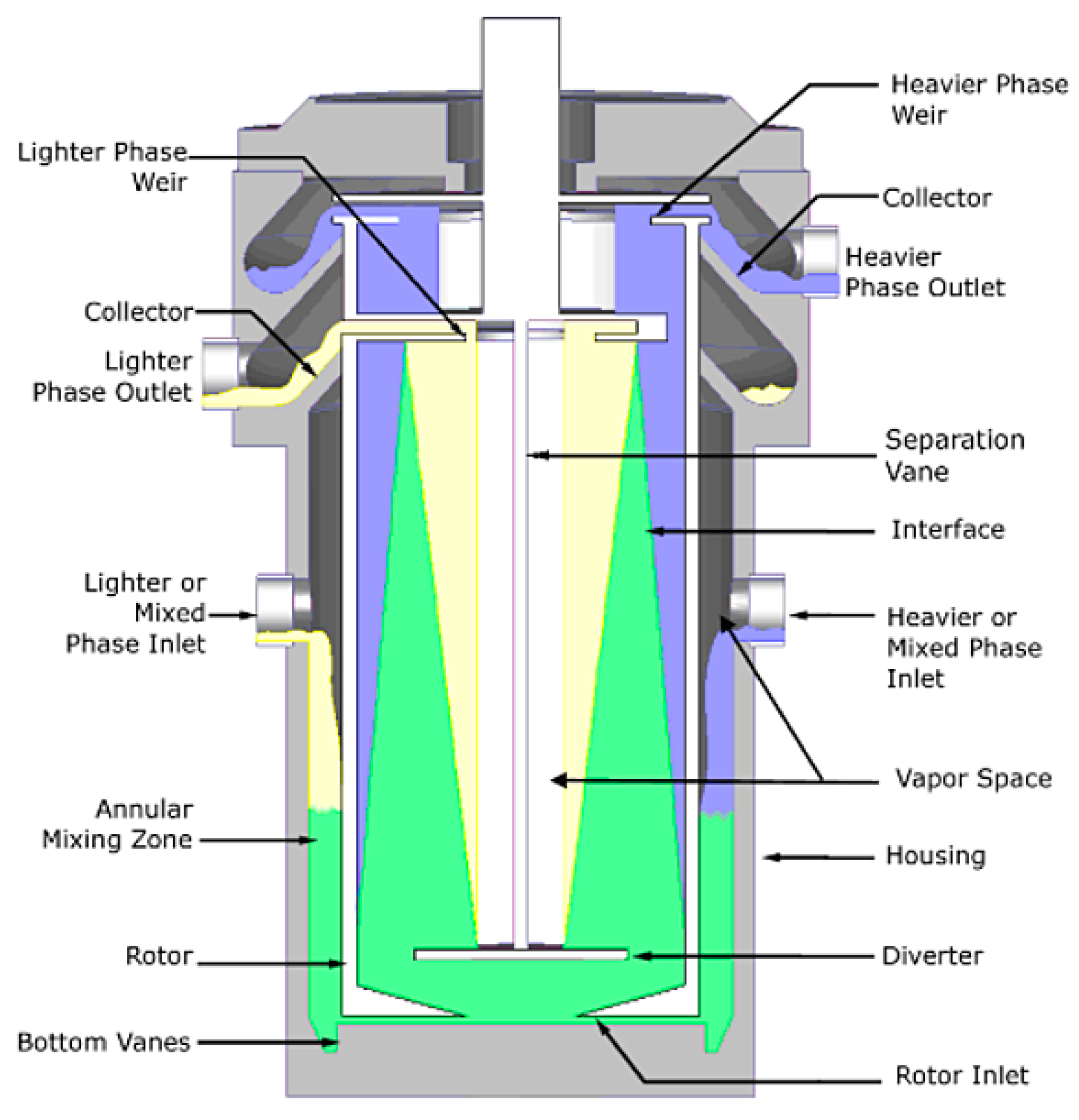
Figure 1 shows a schematic sketch of an extraction centrifuge. The device is axially symmetrical constructed. The housing of the centrifuge is acting as a stator while in the inner part a rotor is spinning. In the gap between rotor and stator, extremely high shear forces effect a very good mixing of the phases, which are introduced either separately (light and heavy phase) or already pre-mixed through one or both inlets. The figure illustrates the mixed fluid in green, the lighter phase fluid in yellow, and the heavier phase fluid in blue. The fluids enter the apparatus through an inlet or hole at the bottom of the rotor. A diverter plate or disk directs the fluid to the inside of the rotor sleeve. Inside the rotor the mixed fluid is forced upward where outlets are located. On the way from the bottom to the top of the rotor the light phase (lower density) is accumulated at the center of the rotor whereas the heavy phase (high density) is accumulated closer to the rotor wall. Each fluid is collected in its own collector ring and then leaves the separator through the heavy and light phase outlets [22]. A similar setup is available within so-called Podbielniaks, which are extraction centrifuges with a horizontal rotation axis.
2.2. Fields of Application
Extractive centrifuges can be applied as devices for liquid-liquid extraction, liquid-liquid separation or even reactions [22,24,25,26,27]. Performing not only extractions but also chemical reactions in extractive centrifuges gained more importance in the recent years. The focus is on biphasic reactions, such as alkylation of p-methoxyphenol with allylbromides or the aldol reaction between methyl isobutyl ketone and benzaldehyde [27]. The extractive centrifuge works as a reaction and separation unit at the same time.
Due to high rotational speeds and g-forces at the wall of the rotor, reaching 1600, the turbulence in the annular mixing zone is extremely high resulting in an excellent mass transfer. Therefore, in the case of extraction, the centrifuge can be considered to represent one theoretical stage or, in other words, showing a separation efficiency of almost one. Due to the high-energy input the volume of extractive centrifuges is significantly smaller compared to other extraction devices (see also Table 1). Compared to standard extraction equipment, such as a mixer-settler, that also reaches comparable separation efficiencies, the centrifuges have severe disadvantages in both the CAPEX and the OPEX. Therefore, extractive centrifuges are typically applied to demanding systems in cases when the application of standard equipment is not feasible, for example systems where short residence times are necessary, systems with poor mass transfer, or systems with difficult phase separation behavior [25]. Another reason for application of extraction centrifuges is their very small footprint combined with an excellent throughput per volume ratio. The centrifuges can be operated as single units or in series, in a co- or counter-current mode.
CINC developed a mixing time extension feature which allows long mixing times up to 5 min for mass transfer reduced systems (example metal extractions).
Due to this feature all parameters:
a. mixing intensity via RPM
b. g-force via RPM
c. phase ratio via flow rates
d. mixing time via size of mixing room and flow rate can be adjusted.
3. Smart Multi-Purpose Production Facilities
Lonza has not yet started a dedicated program to develop container-based modular plants. This is mainly due to the fact that the company has powerful and very flexible multi-purpose plants available on different production sites all over the world. A major characteristic of these plants is that they are used to produce a wide range of different products based on different chemical processes but assess the same equipment (e.g., stirred reactors, distillation columns, extraction assets etc.) which is installed in the plants. Production takes place in campaigns lasting 2–6 months and yielding 10–1000 tons of respective products. This operation mode obviously causes several changeovers throughout the course of a year. In these changeover periods the entire process has to be adapted to a new product which typically means that the unit operations, pumps, tanks etc. has to be re-connected to a new order which is demanded by the specific process. On the one hand the implementation of different processes using the same units demands high flexibility of both, assets and the staff operating the plant. Therefore, the installed equipment is rather general (meaning it can be operated in a wide range of possible conditions) than specifically designed and optimized for of a particular product.
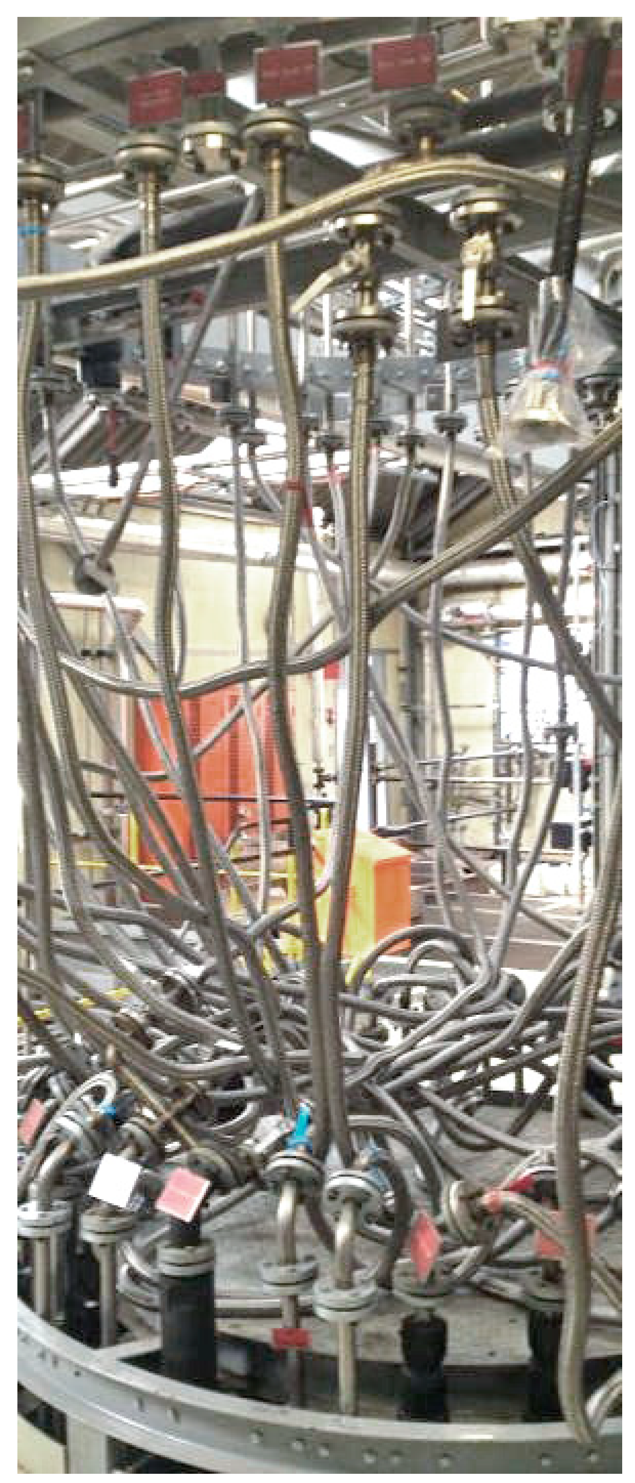
On the other hand, these changeover periods have to be as short as possible in order to maximize the plant utilization. In other words, bringing the equipment to a new order, due to process demands, has to be as fast as possible. For instance, a tank, which is connected to a distillation column in one process is part of an extraction column or used as a simple storage device in another process. Obviously, fixed piping between the equipment hampers quick changeovers. Lonza overcame this challenge by the application of coupling stations. Fixed pipes from the entire plant equipment meet at coupling stations and can be interconnected by flexible hoses according to the demand of the process in almost any desired way (Figure 2). Hence, the order of equipment can be adapted very fast [28]. Subsequent to re-connection, a test run using water ensures that the desired connection is operating in the desired way. The concept of flexible coupling is not really new; examples are shown earlier in [29]. However, it seems that the application of this concept goes further at Lonza, compared to peer companies. The consistent application of coupling stations results in changeover times between two production campaigns of one–two weeks. Within this period all plant adaptions, cleaning procedures, and test runs are conducted. As already mentioned, well-trained and well-educated staff is absolutely mandatory to carry out these highly complex procedures within the short changeover periods.
The coupling stations support the overall flexibility of the production facility but not the flexibility of the single unit operations. Consequently, Lonza has successfully launched a project to resolve this issue. To meet unknown demands of the future, each unit operation should dispose as much functionality as possible. Taking a stirred tank reactor as an example, the functionality and, therefore, flexibility can be increased by equipping this unit with heating and cooling capabilities, a vacuum pump for operations under reduced pressures, a distillation unit or a liquid-liquid phase separation system to run also extractions. However, not all of the additional features are necessary for each process and, as a result, the utilization time is very low. To increase the utilization times of the additional functionalities Lonza chose an approach in which not each reactor is fully equipped but the functionalities are placed on mobile racks that can be coupled with the reactors if necessary. Hence, the number of additional functionalities, and, therefore, the necessary investment could be considerably reduced. The additional modules are flexible and standardized which means that every module consists of a transportable rack, a process control unit, and standard connectors for utilities, electricity and Ethernet. After the connection to the reactor, the equipment automatically communicates with the process control system and can be directly used (plug and produce). Currently, phase separation modules, heating- and cooling-modules, and decanter-modules are available. This concept ensures the flexibility of the plant, reduces changeover periods between production campaigns as well as CAPEX and maintenance costs [11].
Obviously there is a demand, not only at Lonza, for flexible and efficient unit operations that can be adapted to different processes in a fast way. Extractive centrifuges fulfill this demand to a large extend.
4. Extractive Centrifuges at Lonza
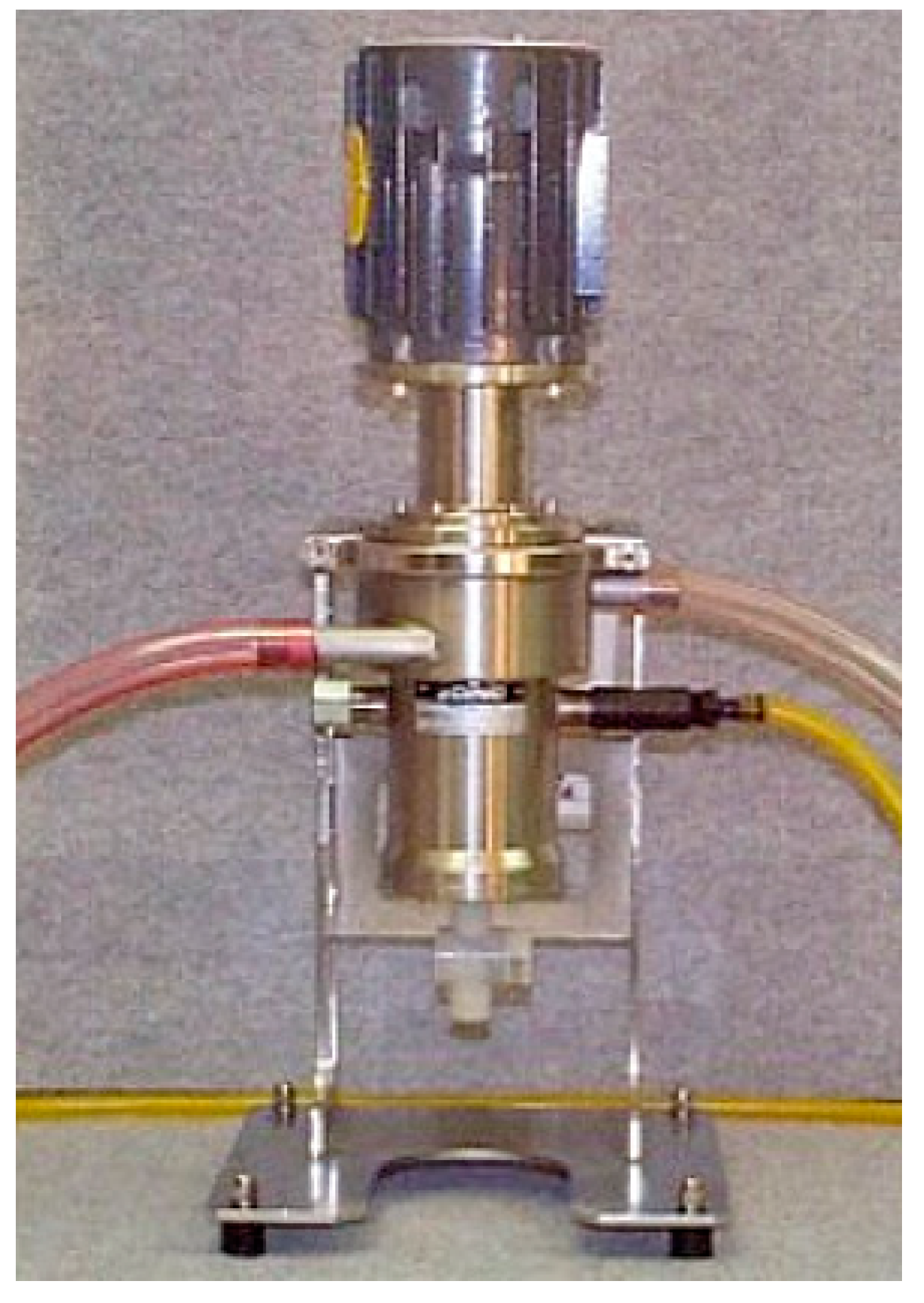
Lonza operates a laboratory CINC extractive centrifuge for proof of concept purposes. The model CS-50 is constructed from stainless steel 1.4571. It can be operated in a temperature range between −30 °C and +100 °C with a maximum rotation speed of 6000 rpm a maximum flow rate of 2 L/min, and possess a flexible weir adjustment.
In the plants, Lonza uses the CINC model CS-250, also constructed from stainless steel 1.4571. The maximum rotational speed is 3450 rpm with a maximum flow rate of 114 L/min.
4.1. Feasibility Studies and Scale-Up
Feasibility studies on a lab scale are mandatory to prove the general applicability of extractive centrifuges. This is given if one or more of the following statements are valid [24,30]:
- Poor Phase separation
- Tendency to form emulsions
- High-energy input necessary
- Low number of theoretical stages necessary (<5) and low construction height obligatory
High-energy input in this context is typically necessary for systems with large density differences and high interfacial tensions at the same time. Table 3 provides an overview of important parameters. Another reason to use extractive centrifuges is their availability in a multi-purpose plant or the absence of alternatives. If additional chemical reactions have to occur within the extractive centrifuge, it must be assured that the reaction kinetics fit to the relatively short residence times of the centrifuges and that neither strong exothermic nor strong endothermic behavior occurs since heat exchange is limited.
Feasibility studies at Lonza are carried out in the CS-50 device (Figure 3). In a first step the liquid-liquid-equilibrium (LLE) and the phase separation is tested in simple experiments. The solvent is added to the original solution and subsequently shaken for 30 s in order to adjust the phase equilibrium. The resulting mixture is then centrifuged in a regular laboratory centrifuge with 2000 U/min and checked if the two phases separate sufficiently. The solvent addition is carried out stepwise (e.g., 5 wt % steps) in order to find an optimum (minimal solvent/feed ratio). This stepwise experimental approach can be skipped in cases when reliable thermodynamic data is available for the considered system allowing the calculation of the LLE and, therefore, the necessary amount of solvent. In the second step, the weir size is calculated for the considered case. The weir is adjustable in all CINC centrifuges and regulates the phase separation. Its size only depends on the density difference between the light and the heavy phase and can be calculated using tables provided by the vendor. For the experiments with the CS-50 device the rotational speed is another adjustable parameter. It is chosen in a way that under given conditions (feed stream and weir size) the outlets of the centrifuge consist of pure light and heavy phase, respectively. In this context, it is absolutely necessary to ensure a sufficient venting of the outlet lines. It has to be avoided that gas blankets occur inside the centrifuge or in the outlet lines close to the unit, since in this case the release of the two phases might collapse. This is on a laboratory scale typically done by ensuring that the outlet lines are never fully filled with liquid: the unit can “breathe”. If solid particles are present in the solution (e.g., due to contamination or chemical reaction), long-time experiments might be necessary to ensure that the particles do not sediment and grow on the rotor, which again will yield in a collapse of the phase separation. Process size units are equipped with a CIP (clean in place) system to remove sedimented particles.
After proving feasibility, meaning that the desired mass transfer is reached, the phase separation works and the device can be operated on a long-term, application on technical scale can be considered.
4.2. Application in Production Facilities
This chapter provides some examples to illustrate the variety of potential applications of extractive centrifuges within production process. Lonza uses the CINC model CS-250 in production whose throughput per hour of 480 L is already sufficient for many of Lonza´s processes. It is the smallest production size centrifuge in the CINC program and with a footprint of approximately 1 m2 and a weight of 400 kg relatively easy to handle. This type of centrifuge is typically used in multi-purpose plants for different processes. To connect the device with the process, no fixed piping is necessary. Flexible hoses are sufficient. Lonza typically feeds the device from two feed tanks, one for the organic and one for the aqueous phase, respectively, using feasible pumps and send the process outlets (light and heavy phases) to tanks which are placed beneath the centrifuge, hence no additional pumps are necessary for that transfer. The centrifuge can also be connected directly to the unit operations prior and subsequent to the device. This operation mode reduces the need of auxiliary tanks. However, it is more prone for process disturbances which frequently occur in multi-purpose productions. The application of feed and product tanks absorbs disturbances and allows a smooth and controlled operation of the centrifuge. Lonza has a well-established risk analysis method in order to minimize operational and process safety issues. Extraction centrifuges can easily be integrated in this procedure.
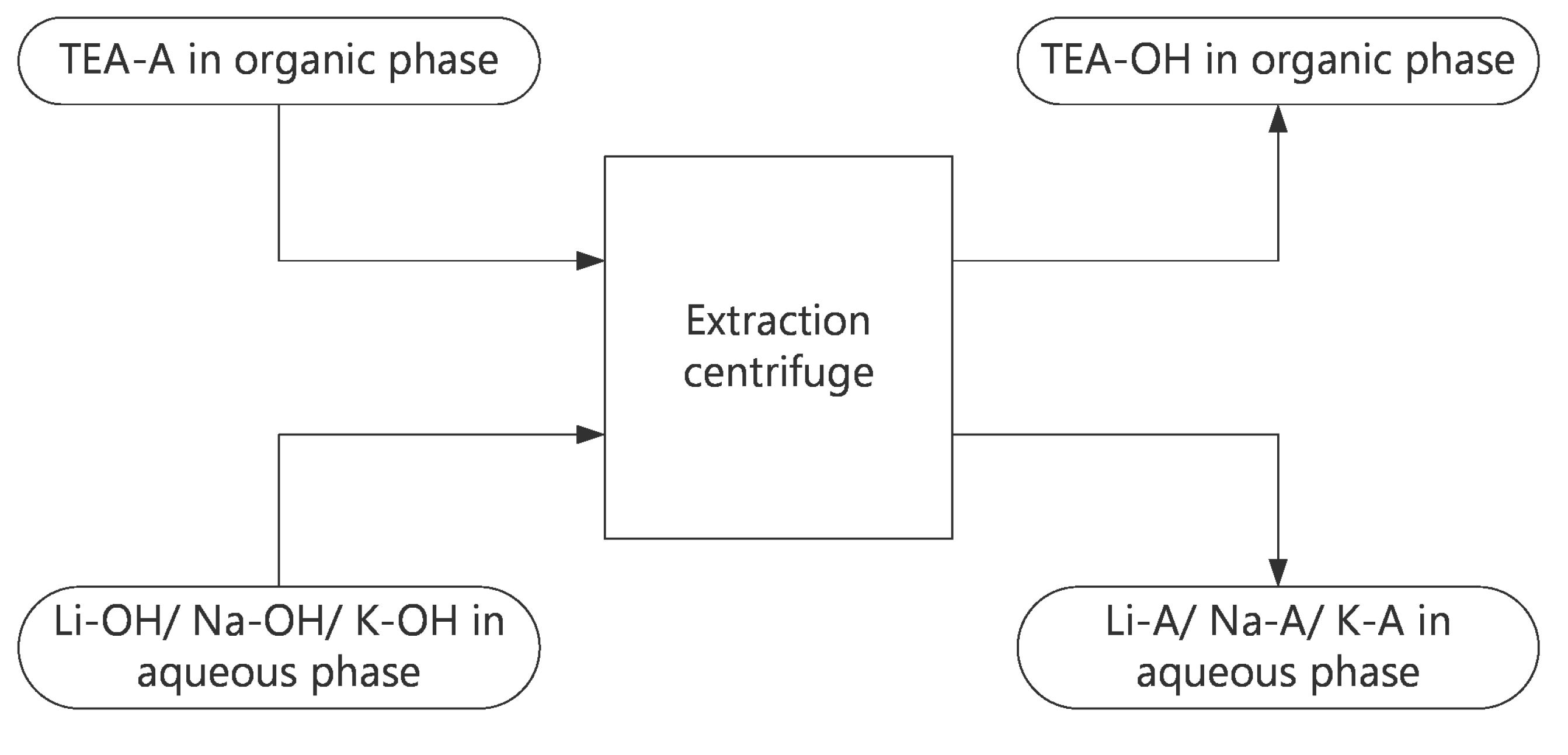
The process considered here produces mainly a lithium-based salt, which could be used as a stabilizing compound in electrolytes of lithium ionic battery cells. These cells are the key elements of automotive batteries. A further application of the lithium-based salt is as an antistatic agent in touch screens. By very small adaptions of the process, other cations besides lithium (e.g., K+, Na+) can be attached to the corresponding anion yielding in a wide range of other promising electrolytes. The ion exchange reaction is carried out in the extractive centrifuge where the triethylamine-based anion (TEA-A), which itself is an intermediate in the process produced from the protonated form of the anion (H-A) by several steps, is fed into the centrifuge in an organic solution. Nitriles (e.g., acetonitrile) are established solvents for TEA-A and commonly used. In addition to this phase containing organic product, an aqueous phase containing the desired exchange-ion (e.g., Li+, Na+, K+) in the hydroxyl form (e.g,. NaOH) and solved in water is simultaneously fed to the centrifuge as illustrated in Figure 4. Both phases are immiscible and form a wide miscibility gap. Within the annular mixing zone of the centrifuge, intense mixing occurs and the triethylammonium cation is changed against the lithium cation resulting in the desired product, remaining in the organic phase, and the solid byproduct triethylammonium hydroxide, remaining in the aqueous phase. As ion exchange reactions can be carried out with short residence times, reaction centrifuges are therefore well suited. Within the described process, the mean residence time is <1 min and the conversion of TEA-A to the desired product is close to 100%. However, a major issue occurs in this example, going back to the usage of a suspension as one feed and the production of solid byproducts. The occurrence of solid particles in strongly rotation devices can lead to the situation when the solid particles are not properly discharged off the device but accumulate and grow on the rotating or the static part which will decrease the volume of the section where the phase separation takes place. This results again in an improper phase separation after a certain period of operation and in a worst-case scenario to the failure of the entire unit. The adjustment of solid concentration in the feed stream and the rotating speed in order to completely avoid solid formation on the rotating parts are therefore absolutely mandatory.
Within the same process, not only the mentioned ion exchange takes place within an extraction centrifuge but also the pre-treatment of organic solvents. A large amount of organic solvents, such as acetonitrile, is used and require re-work before being recycled into the process for economic and ecological reasons instead of sending the stream to incineration. The main re-work step is a rectification. However due to the production process the solvents contain unacceptable concentrations of chlorides which would accumulate in the bottoms of the distillation column causing severe damage by pit corrosion in stainless steel. Hence, the chlorides have to be removed before the solvents enter the rectification column. This is done by a step in which the solvents are washed with a 25% sodium hydroxide solution. Again, the two phases enter simultaneously the extraction centrifuge, come in contact and separate with mean residence times of <1 min. The chloride content of the organic phase is reduced from several 100 ppm of chloride to around 10 ppm, which is acceptable for the subsequent distillation made from stainless steel.
A comparable application of an extraction centrifuge was established during an optimization of one of Lonza’s largest processes. After chlorination in aqueous phase, the product mixture forms an organic phase. With traditional phase separation methods, it was not possible in the past to separate both phases completely. Small water droplets with high chloride concentrations remained in the organic phase and went into the subsequent rectification setup. In the past this effect resulted in short maintenance circles and even severe operation failures due to blocking and pit corrosion issues. A feasibility study with the target of implementing an extraction centrifuge into the process proved the success of this approach and based on these results it was easy to set up a highly profitable business case. After implementation, the maintenance periods could be extended by a significant factor and corrosion was not observed in the rectification column anymore since then. An additional positive effect is that within the rectification higher product qualities can be obtained due to the fact that water is present only at very small concentrations.
Apart from multi-step chemical synthesis followed by product isolation it is possible to carry out complex rework sequences of fermentation broths within Lonza´s multi-purpose plants. These fermentation broths often contain products that cannot be isolated by distillation or rectification due to their high molecular weights and sensitivity towards high temperatures. Thus, extraction could be the process of choice if the challenges of phase separation can be overcome. In one of these processes to be carried out in a multi-purpose plant, side products are removed by selective esterification, resulting in a mixture containing a variety of surface-active molecules that hamper phase-separation. Implementation of an extraction centrifuge into this process resulted in a breakthrough as a highly pure product was obtained, and no further treatment was required for its application.
5. Conclusions
In order to meet global trends of higher market volatility, shorter product life cycles, increasing customer demands, and shorter development and production cycles, as well as the transition to flexible production plants are the key approaches followed up by process operating companies. Production in modular and flexible plants requires new types of apparatuses, as traditional unit operations are limited due to their inherent geometrical factors, small ranges of scalability and a lack of flexibility and modularity. Even in a highly flexible production environment, such as in Lonza’s multi-purpose plants, modular assets are required to further increase the flexibility. Extraction centrifuges are a good example to illustrate this flexibility increase if implemented into a process. A fast and efficient design and scale-up process allows fast implementation into processes on technical scale, as can be demonstrated on practical examples in commercial processes within this paper.
Author Contributions
T.G. and A.K. provided the major part of practical results to the paper while T.G. and B.C.S. contributed theoretical input. The publication was written by T.G. and B.C.S. while edited by all three authors.
Funding
This research received no external funding.
Acknowledgments
The authors grateful acknowledge the support and valuable inputs of Mathias Vornefeld of CINC GmbH & Co Kg, Germany and of Anna-Christina Hormes.
Conflicts of Interest
The authors declare no conflict of interest.
References
- Kiss, A.A. Distillation technology—Still young and full of breakthrough opportunities. J. Chem. Technol. Biotechnol. 2014, 89, 479–498. [Google Scholar] [CrossRef]
- Asprion, N.; Kaibel, G. Dividing wall columns: Fundamentals and recent advances. Chem. Eng. Process. 2010, 49, 139–146. [Google Scholar] [CrossRef]
- Staak, D.; Grützner, T.; Schwegler, B.; Roederer, D. Dividing wall column for industrial multipurpose use. Chem. Eng. Process. 2014, 75, 48–57. [Google Scholar] [CrossRef]
- Staak, D.; Grützner, T. Process integration by application of an extractive dividing-wall-column: An industrial case study. Chem. Eng. Res. Des. 2017, 123, 120–129. [Google Scholar] [CrossRef]
- Brodhagen, A.; Grünewald, M.; Kleiner, M.; Lier, S. Erhöhung der Wirtschaftlichkeit durch beschleunigte Produkt- und Prozessentwicklung mit Hilfe modularer und skalierbarer Apparate. Chem. Ing. Tech. 2012, 84, 624–632. [Google Scholar] [CrossRef]
- Lier, S.; Wörsdörfer, D.; Grünewald, M. Transformable Production Concepts: Flexible, Mobile, Decentralized, Modular, Fast. ChemBioEng Rev. 2016, 3, 16–25. [Google Scholar] [CrossRef]
- Hohmann, L.; Kössel, K.; Kockmann, N.; Schembecker, G.; Bramsiepe, C. Modules in process industry—A life cycle definition. Chem. Eng. Process. Process Intensif. 2017, 111, 115–126. [Google Scholar] [CrossRef]
- Lang, J.; Stenger, F.; Schütte, R. Chemieanlage der Zukunft—Unikate und/oder Module. Chem. Ing. Tech. 2012, 84, 883–884. [Google Scholar]
- Bieringer, T.; Buchholz, S.; Kockmann, N. Future Production Concepts in the Chemical Industry: Modular—Small-Scale—Continuous. Chem. Eng. Technol. 2013, 36, 900–910. [Google Scholar] [CrossRef]
- Roberge, D.; Zimmermann, B.; Rainone, F.; Gottsponer, M.; Eyholzer, M.; Kockmann, N. Microreactor Technology and Continuous Processes in the Fine Chemical and Pharmaceutical Industry: Is the Revolution Underway? Org. Process Res. Dev. 2008, 12, 905–910. [Google Scholar] [CrossRef]
- Grützner, T.; Seyfang, B.; Zollinger, D.; Kuenzle, N. Reducing time-to-market by innovative development and production strategies. Chem. Eng. Technol. 2016, 39, 1835–1844. [Google Scholar] [CrossRef]
- Fletcher, P.; Haswell, S.; Pompo-Villar, E.; Warrington, B.; Watts, P.; Wong, S.; Zhang, X. Micro reactors: Principles and applications in organic synthesis. Tetrahedron 2002, 38, 4735–4757. [Google Scholar] [CrossRef]
- Sundberg, A. Micro-Scale Distillation and Microplants in Process Development. Doctoral Dissertation, Aalto University, Helsinki, Finland, 2014. [Google Scholar]
- Wellsandt, T.; Stanisch, B.; Strube, J. Development of Micro Separation Technology Modules. Part 1: Liquid-Liquid Extraction. Chem. Ing. Tech. 2015, 87, 1198–1206. [Google Scholar] [CrossRef]
- Stanisch, B.; Wellsandt, T.; Strube, J. Development of Micro Separation Technology Modules. Part 2: Distillation. Chem. Ing. Tech. 2015, 87, 1207–1214. [Google Scholar] [CrossRef]
- Lier, S.; Paul, S.; Ferdinand, D.; Grünewald, M. Modulare Verfahrenstechnik: Apparateentwicklung für wandlungsfähige Produktionssysteme. Chem. Ing. Tech. 2016, 88, 1444–1454. [Google Scholar] [CrossRef]
- Sirkar, K.K. Membranes, Phase Interfaces, and Separations: Novel Techniques and Membranes—An Overview. Ind. Eng. Chem. Res. 2008, 47, 5250–5266. [Google Scholar] [CrossRef]
- Li, X.; Liu, Y.; Li, Z.; Wang, X. Continuous distillation experiment with rotating packed bed. Chin. J. Chem. Eng. 2008, 16, 656–662. [Google Scholar] [CrossRef]
- Sudhoff, D.; Leimbrink, M.; Schleinitz, M.; Górak, A.; Lutze, P. Modelling, design and flexibility analysis of rotating packed beds for distillation. Chem. Eng. Res. Des. 2015, 94, 72–89. [Google Scholar] [CrossRef]
- Schuur, B.; Jansma, W.; Winkelman, J.; Heeres, H. Determination of the interfacial area of a continuous integrated mixer/separator (CINC) using a chemical reaction method. Chem. Eng. Process. 2008, 47, 1484–1491. [Google Scholar] [CrossRef] [Green Version]
- Schuur, B.; Kraai, G.; Winkelman, J.; Heeres, H. Hydrodynamic features of centrifugal contactor separators: Experimental studies on liquid hold-up, residence time distribution, phase behavior and drop size distributions. Chem. Eng. Process. 2012, 55, 8–19. [Google Scholar] [CrossRef]
- Technical Data. Available online: www.cinc.de (accessed on 25 September 2018).
- Monostage Liquid/Liquid Centrifugal Contactors (Model BXP). Rousselet Robatel Company Presentation 2017. Available online: http://www.rousselet-robatel.com/brochures/Monostage_centrifugal_contactors_BXP_Eng.pdf (accessed on 25 September 2018).
- Birdwell, J.; McFarlane, J.; Hunt, R.; Luo, H.; DePaoli, D. Separation of Ionic Liquid Dispersions in Centrifugal Solvent Extraction Contactors. Sep. Sci. Technol. 2005, 41, 2205–2223. [Google Scholar] [CrossRef]
- Goedecke, R. Fluidverfahrenstechnik, Grundlagen, Methodik, Technik, Praxis; Wiley-VCH: Weinheim, Germany, 2006; ISBN 978-3-527-31198-9. [Google Scholar]
- Kraai, G.; van Zwol, F.; Schuur, B.; Heeres, H.; de Vries, J. Two-phase (bio) catalytic reactions in a table-top centrifugal contact separator. Angew. Chem. Int. Ed. 2008, 47, 3905–3908. [Google Scholar] [CrossRef] [PubMed]
- Allemann, C.; Marti, R.; Vorlet, O.; Martin, O.; Riedlberger, P.; Leonhardt, T.; Gössi, A.; Riedl, W.; Segura, J.-M.; Zinn, M.; et al. Continuous Processes and Flow Chemistry at the Universities of Applied Sciences in Switzerland. Chimia 2017, 71, 525–527. [Google Scholar] [CrossRef] [PubMed]
- Heckmann, G.; Previdoli, F.; Riedel, T.; Ruppen, D.; Veghini, D.; Zacher, U. Process development and production concepts for the manufacturing of organic fine chemicals at LONZA. Chimia 2006, 60, 530–533. [Google Scholar] [CrossRef]
- Rauch, J. Mehrproduktanlagen; Wiley-VCH: Weinheim, Germany, 1998. [Google Scholar]
- Brandt, H.; Reissinger, K.-H.; Schröter, J. Moderne Flüssig-flüssig-Extraktoren—Übersicht und Auswahlkriterien. Chem. Ing. Tech. 1978, 50, 345–354. [Google Scholar] [CrossRef]
Figure 1.
Principle of an extraction centrifuge (courtesy of CINC Inc.).

Figure 2.
Flexible hoses as interconnections between fixed equipment piping in a multi-purpose-plant coupling station of Lonza AG.
Figure 2.
Flexible hoses as interconnections between fixed equipment piping in a multi-purpose-plant coupling station of Lonza AG.

Figure 3.
Laboratory scale extraction centrifuge (courtesy of CINC Inc.).

Figure 4.
Simplified process scheme of application 1.


Table 1.
Current model range of CINC extractive centrifuges [22].
Table 1.
Current model range of CINC extractive centrifuges [22].
| Parameter | V02/CS50 | V10/CS 250 | CS 330 | V16 | V20/CS 500 |
|---|---|---|---|---|---|
| Flow rate (l/min) | 0.01–1 | 1.0–100 | 1.0–160 | 1.0–300 | 1.0–750 |
| L × W × H (cm) | 30 × 30 × 60 | 70 × 70 × 170 | 105 × 105 × 214 | 112 × 112 × 230 | 120 × 120 × 260 |
| Mass (kg) | 30 | 400 | 900 | 1400 | 2000 |
| Rotor rpm | 0–6000 | 0–3000 | 0–3000 | 0–2400 | 0–2100 |
| g-force | 0–1000 | 0–1250 | 0–1600 | 0–1250 | 0–1250 |
Table 2.
Current model range of ROUSSELET ROBATEL extractive centrifuges [23].
Table 2.
Current model range of ROUSSELET ROBATEL extractive centrifuges [23].
| Parameter | BXP012 | BXP025 | BXP040 | BXP080 | BXP190 | BXP320 | BXP360 | BXP520 |
|---|---|---|---|---|---|---|---|---|
| Flow rate (l/min) | 0–0.03 | 0–0.2 | 0.01–1 | 1.0–11 | 1.0–60 | 1.0–230 | 1.0–460 | 1.0–1000 |
| L × W × H (cm) | 10 × 10 × 29 | 17 × 17 × 48 | 18 × 18 × 49 | 38 × 38 × 57 | 55 × 55 × 130 | 94 × 94 × 155 | 104 × 104 × 185 | 133 × 133 × 230 |
| Mass (kg) | n.a. | n.a. | n.a. | n.a. | n.a. | n.a. | n.a. | n.a. |
| Rotor rpm | 0–10,000 | 0–4000 | 0–3600 | 0–3600 | 0–3500 | 0–3500 | 0–3500 | 0–1750 |
| g-force | 671 | 224 | 290 | 580 | 1377 | 2318 | 2608 | 890 |
Table 3.
Ranges for important properties for liquid-liquid-extraction [24].
Table 3.
Ranges for important properties for liquid-liquid-extraction [24].
| Density Difference | Small Δρ ≤ 50 kg/m3 | Medium 50 kg/m3 ≤ Δρ ≤ 250 kg/m3 | Large Δρ ≥ 250 kg/m3 |
|---|---|---|---|
| Viscosity | Similar to water η ≤ 3 mPas | Increased 3 mPas ≤ η ≤ 10 mPas | high η ≥ 10 mPas |
| Interfacial tension | Small σ ≤ 5 mN/m | Medium 5 mN/m ≤ σ ≤ 15 mN/m | Large σ ≥ 15 mN/m |
| Settling time | Well coalescing tE ≤ 60 s | Inhibited coalescence 60 s ≤ tE ≤ 300 s | Bad coalescence tE ≥ 300 s |
© 2019 by the authors. Licensee MDPI, Basel, Switzerland. This article is an open access article distributed under the terms and conditions of the Creative Commons Attribution (CC BY) license (http://creativecommons.org/licenses/by/4.0/).
Share and Cite
MDPI and ACS Style
Seyfang, B.C.; Klein, A.; Grützner, T. Extraction Centrifuges—Intensified Equipment Facilitating Modular and Flexible Plant Concepts. ChemEngineering 2019, 3, 17. https://doi.org/10.3390/chemengineering3010017
AMA Style
Seyfang BC, Klein A, Grützner T. Extraction Centrifuges—Intensified Equipment Facilitating Modular and Flexible Plant Concepts. ChemEngineering. 2019; 3(1):17. https://doi.org/10.3390/chemengineering3010017
Chicago/Turabian StyleSeyfang, Bernhard C., Andreas Klein, and Thomas Grützner. 2019. "Extraction Centrifuges—Intensified Equipment Facilitating Modular and Flexible Plant Concepts" ChemEngineering 3, no. 1: 17. https://doi.org/10.3390/chemengineering3010017