Transition Metal–Nitrogen–Carbon (M–N–C) Catalysts for Oxygen Reduction Reaction. Insights on Synthesis and Performance in Polymer Electrolyte Fuel Cells


Dipartimento di Scienza Applicata e Tecnologia, Politecnico di Torino, Corso Duca degli Abruzzi 24, 10129 Torino, Italy
ChemEngineering 2019, 3(1), 16; https://doi.org/10.3390/chemengineering3010016
Submission received: 11 December 2018
/
Revised: 21 January 2019
/
Accepted: 31 January 2019
/
Published: 11 February 2019
(This article belongs to the Special Issue Functional Materials for Renewable Energy Technologies)
Abstract
:Platinum group metal (PGM)-free catalysts for oxygen reduction reaction (ORR) have attracted increasing interest as potential candidates to replace Pt, in the view of a future widespread commercialization of polymer electrolyte fuel cell (PEFC) devices, especially for automotive applications. Among different types of PGM-free catalysts, M–N–C materials appear to be the most promising ones in terms of activity. These catalysts can be produced using a wide variety of precursors containing C, N, and one (or more) active transition metal (mostly Fe or Co). The catalysts synthesis methods can be very different, even though they usually involve at least one pyrolysis step. In this review, five different synthesis methods are proposed, and described in detail. Several catalysts, produced approximately in the last decade, were analyzed in terms of performance in rotating disc electrode (RDE), and in H2/O2 or H2/air PEFC. The catalysts are subdivided in five different categories corresponding to the five synthesis methods described, and the RDE and PEFC performance is put in relation with the synthesis method.
1. Introduction
The extensive use of fossil fuels has led to severe environmental issues, and the effects of climate change are becoming more impactful every day [1]. Consequently, in the near future, the fraction of electricity produced via renewables will have to increase considerably, to limit further emissions of CO2 in the atmosphere. Thus, the dependence on non-renewable energy sources like oil, gas, and coal must be reduced, to favor the transition to an emissions-free way to produce energy [2]. In this context, the development of efficient electrochemical energy conversion processes will be essential [3]. H2 represents a sustainable and non-polluting energy carrier that can be used in mobile and stationary power generators [4]. H2 can be obtained from water electrolysis using electricity produced by renewable energy sources. In this case, H2 production and use would be part of a completely emission-free, clean, and sustainable cycle [5].
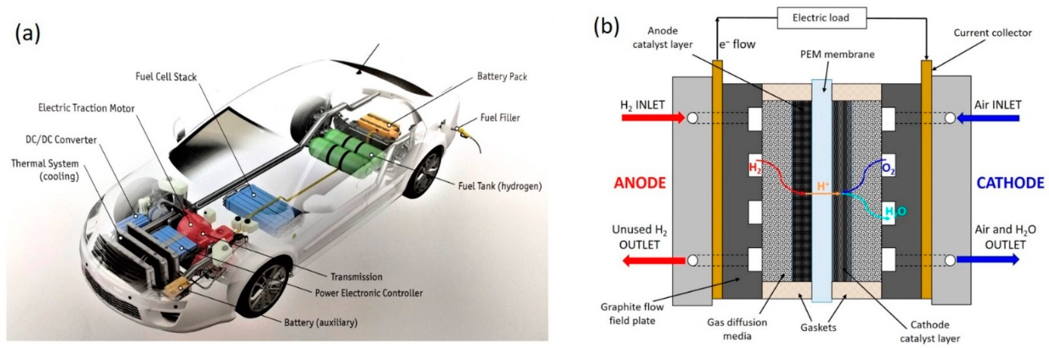
A fundamental advance towards a H2-based energy system are fuel cell vehicles (FCVs). Thus far, several car manufacturers have already put on the market fuel-cell car models, in areas where hydrogen fueling stations are available [3]. Nevertheless, several challenges must still be overcome before FCVs will become a successful and competitive alternative for consumers [6]. A representation of an FCV, with details showing the core components of the propulsion system, is shown in Figure 1a.
A fuel cell is a device that directly converts the chemical energy of a fuel and an oxidant into electrical energy. This happens by means of electrochemical reactions that take place at the electrodes (anode and cathode) [7]. Polymer Electrolyte Fuel Cells (PEFCs) utilize H2 as fuel and O2 from the air as oxidant. PEFCs are advantageous for automotive applications because they operate close to ambient conditions (below 100 °C), allowing fast start-up and shut-down [8].
The basic structure of a PEFC consists of a solid electrolyte (a polymeric membrane, which conducts H+ ions) in contact with a porous anode and cathode on either side. A schematic representation of a single PEFC, with the reactants, products, H+ ions, and electrons conduction directions through the cell, is shown in Figure 1b. The whole membrane and electrodes ensemble is called Membrane Electrode Assembly (MEA) [4].
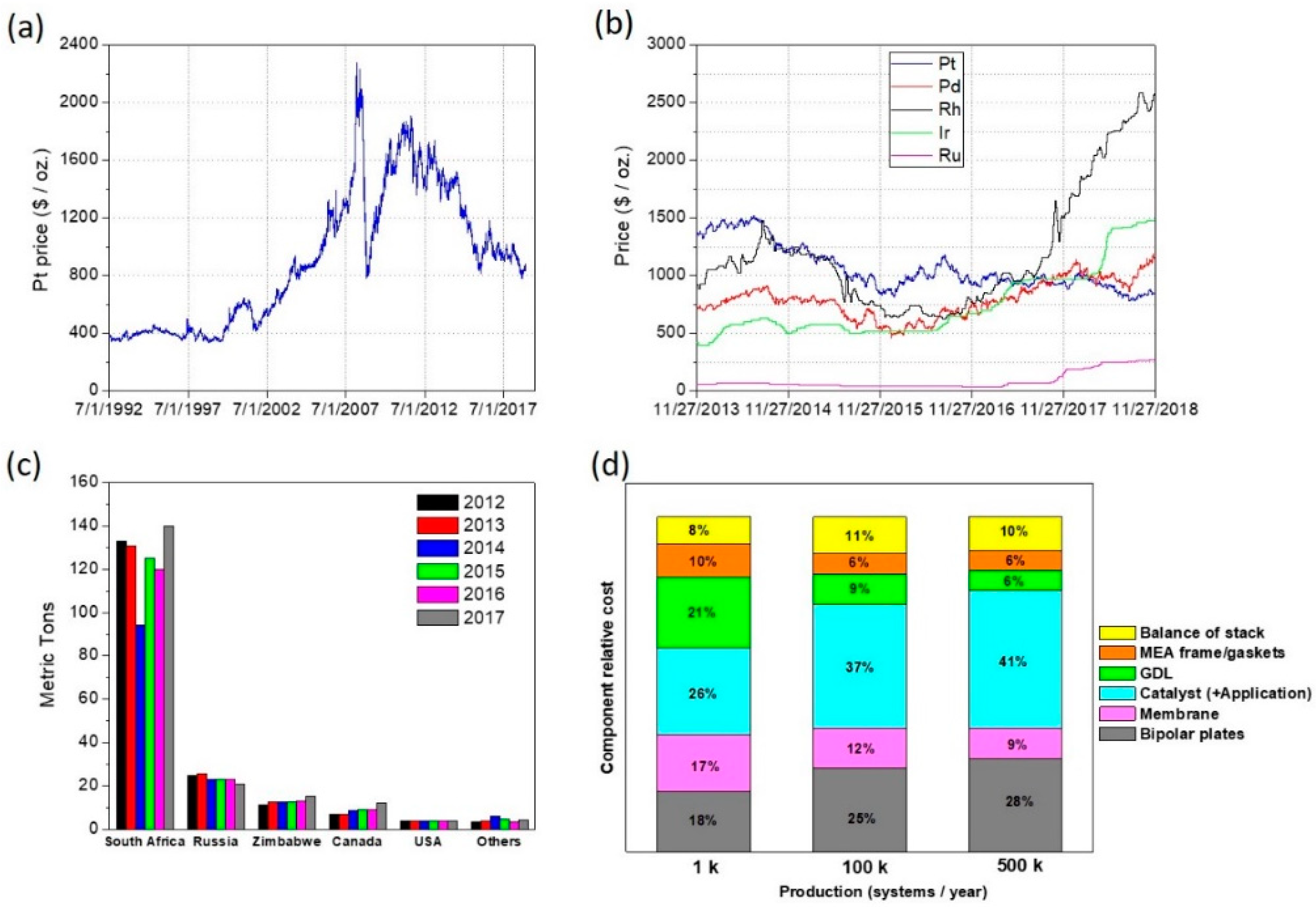
To let the electrochemical reactions occur at such low temperatures, the presence of a catalyst is required at both electrodes. Pt is the best catalyst for both the hydrogen oxidation reaction (HOR) and the oxygen reduction reaction (ORR) [9,10], and its use has been until now one of the main impediments to the widespread commercialization of PEFC devices. Pt and the other Platinum Group Metals (PGMs) are costly raw materials that suffer of price volatility on the stock exchange market (see Figure 2a,b) [11]. Moreover, the majority of Pt mining production is concentrated in South Africa and in a few other countries, as shown in Figure 2c [12]; this could cause provision issues in a scenario of massive production.
In the last decade, significant improvements have been obtained in reducing the amount of Pt used in PEFC stacks [13]. However, in the scenario of a complete replacement of the entire internal combustion engine car fleet with FCVs, considering the estimated total world Pt reserves, and a reasonable Pt recycling rate, the Pt cost is expected to rise tremendously [14,15].
According to the most recent estimations of the U.S.A. Department of Energy, the cost of a PEFC stack is dictated in large portion by the Pt-based catalyst cost. This portion is getting larger as the number of stack manufactured per year increases, as shown in Figure 2d [16].
It is easy to understand how the development of cost effective, highly performing, and durable PGM-free catalysts as alternative to Pt would represent a fundamental breakthrough for the widespread commercialization of PEFC devices. In this regard, it has to be considered that the Pt loading in PEFCs is usually higher on the cathode than on the anode. In fact, in the acid environment of PEFC (around pH 1), the HOR kinetics on Pt is much faster than the ORR. Consequently, about 5–10 times more Pt is needed at the cathode than at the anode, and for this reason the research is focusing predominantly on PGM-free catalysts for ORR [12].
Among different types of PGM-free catalysts for ORR, the most promising are carbon-based materials containing transition metal/nitrogen functionalities, hereinafter indicated as M–N–C. The active ensembles present on these catalysts are indicated as M–Nx/C, where M is a 4th period d-transition metal (e.g., Fe, Co, Mn), and x indicates the number of N atoms coordinating the metal. For example x = 4 for a pyridinic in-plane coordination in a single graphitic plane, or x = 2 + 2 for a pyridinic coordination at the edges of two graphitic planes [17,18].
M–N–C catalysts have gained increasing attention due to their promising catalytic activity, along with the utilization of abundant and inexpensive precursors for their synthesis [19]. In 1964, it was demonstrated that metallized macrocyclic molecules (i.e.,, porphyrins and phthalocyanines) could act as ORR electrocatalysts [20]. However, their stability in acidic medium is poor, due to decomposition. Subsequently, it was discovered that submitting these molecules to a heat treatment at high temperature (700–1100 °C) in inert atmosphere increased both the activity and the stability in acidic medium [21]. During the heat treatment, a carbonization takes place, with simultaneous incorporation and of N and metal atoms in the carbonaceous matrix, to form the active and more stable M–Nx/C moieties [22,23]. Subsequently, it was discovered that, due to the structure modification occurring during the heat treatment (pyrolysis), the use of the metallized macrocycles was not strictly required. Catalytically active materials can be obtained from pyrolysis of a wide variety of chemical precursors, provided that a source of carbon (carbon support, organic molecule, polymer), a source of nitrogen (N-containing organic molecule, polymer, or reactive gas like NH3), and an active transition metal source (e.g., salt) are present [24,25,26].
The aim of this review is to present and analyze the most common and effective methods used to produce M–N–C catalysts for ORR. The catalysts are divided into five different groups, based on the synthesis method. For each group, the performance of several different catalyst, developed approximately in the last decade (2008–2018) is reported. Both the performance in rotating disk electrode (RDE), and in a single PEFC were considered, when available. For RDE tests, the performance is also put in relation to the catalyst loading on the working electrode. For the single PEFC experiments, the results of H2/O2 and H2/air tests are shown separately. Moreover, the PEFC performance is put in relation with the cathode catalyst loading, and with the cell total PGM loading, considering the amount of Pt used at the anode.
In this review, only H2-fueled acidic membrane PEFCs were considered, thus excluding direct alcohol (and other types of fuels) systems. The application in anion exchange membrane fuel cells (AEMFCs) was not considered in this review. Even though the use of M–N–C catalysts for ORR in alkaline medium has been reported extensively in the literature [27,28,29,30], only few works have been published showing the application of such catalysts in H2-fueled AEMFC with promising performance [31,32,33]. In fact, AEMFC research is currently much focused on the membrane development (durability, conductivity, resistance to carbonation) [34,35] and on understanding the water management of the cell [36]. In these systems, the ORR catalyst activity should not represent the main problem, given the enhanced ORR kinetics in alkaline medium on several different types of PGM-free materials [37,38].
2. Different Approaches for M–N–C Catalysts Synthesis
The aim of this section is to present and discuss the most widely used methods for the synthesis of M–N–C catalysts for ORR that have been reported in the literature. The literature about this topic is particularly ample, and many works have been published in the last decades, as described in several comprehensive reviews [13,24,25,39,40,41]. Thus, the amount of papers that explore the use of different chemical precursors and synthesis routes, showing physicochemical, morphological, and electrochemical (mostly using RDE) characterization, is relevant.
The works analyzed in the following subsections, represent a selection among the literature published approximately in the last decade. A particular attention has been paid to select works where the catalyst were tested in RDE in acidic electrolyte, and showing PEFC testing results, providing evidence about the catalyst performance at in-device level. An overview of the RDE and PEFC performance is provided graphically, enabling a quick comparison between the catalysts synthesized via different approaches.
In this analysis, we divided the catalysts into five different categories. For the sake of brevity, hereinafter we will indicate the catalysts synthesis methods as follows:
- Method 1: catalysts derived from carbon support and nitrogen containing molecule (Section 2.1);
- Method 2: catalysts derived from nitrogen containing polymer (Section 2.2);
- Method 3: catalysts derived from silica template and organic precursors (Hard Template Method) (Section 2.3);
- Method 4: catalysts derived from metal organic frameworks (MOFs) (Section 2.4);
- Method 5: catalysts derived from MOFs and additional precursors (Section 2.5).
It is important to note that the proposed subdivision does not represent a universally recognized standard. Nevertheless, it may be helpful to point out what is behind the idea of producing pyrolyzed M–N–C materials that possess significantly high ORR activity in acidic medium. Materials with a certain catalytic activity towards ORR can be obtained also without the presence of any metal, as demonstrated in several studies, where various C and N precursors are combined [42,43,44,45]. However, their activity in acidic medium is remarkably lower than their metal-containing counterparts, especially when the most active transition metals (Fe, Co, Mn, etc.) are used. This is true for both pyrolyzed and non-pyrolyzed materials [23,46,47,48,49,50,51].
2.1. Method 1: Catalysts Derived from Carbon Support and Nitrogen Containing Molecule
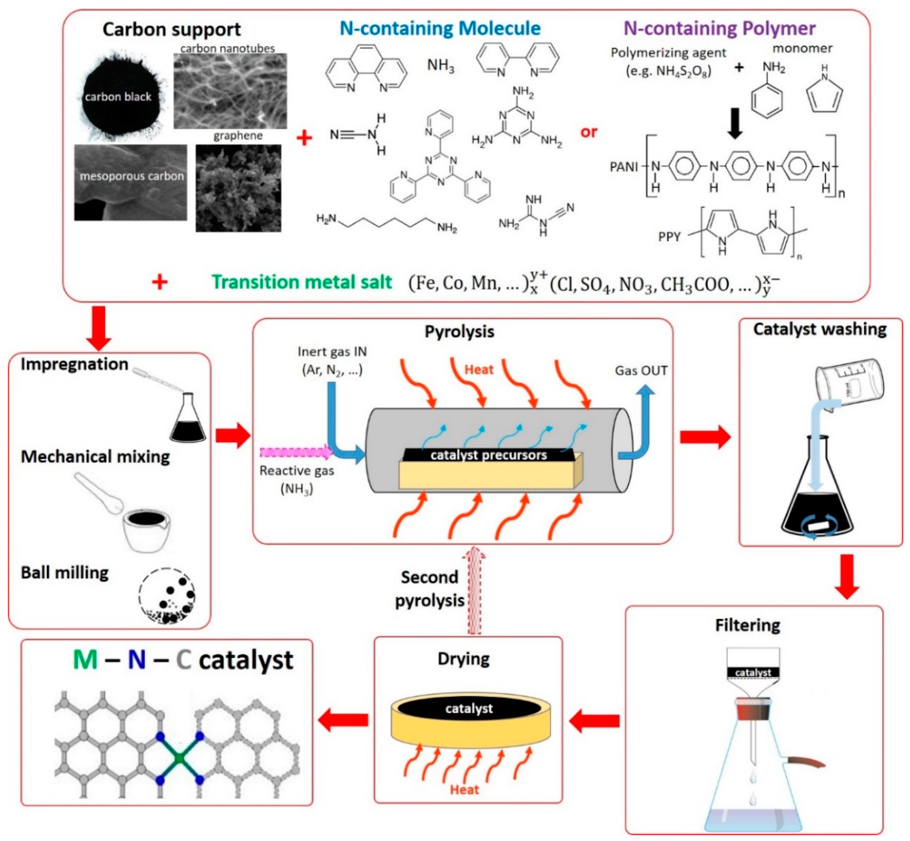
In this synthesis approach, the three key elements, C, N, and metal (M), necessary to produce the M–N–C catalyst, come from separate precursors. Figure 3 represents a scheme of a typical synthesis path that can be followed to obtain the catalyst.
The carbonaceous material is used with a double purpose: provide an excess of C atoms, and act as an electronically conductive support matrix for the ORR active sites. To be effective as support, the C-based material must have a sufficiently high surface area (to ensure high active sites density) and a good electrical conductivity. Several types of carbon-based materials have been used, such as different types of carbon black (e.g., Ketjen Black, Vulcan XC72, Black Pearls, acetylene black) [46,52,53,54,55,56,57], carbon nanotubes [58,59,60,61], carbon nano-networks [62], reduced graphene oxide [47,63,64,65,66], and ordered mesoporous carbons [50,67,68]. Some studies have put in evidence the great importance of the carbon support to provide a good ORR activity to the catalyst. For example, it was demonstrated that the amount of disordered carbon (as detected by Raman spectroscopy) and the weight loss during the pyrolysis (assessed by Thermogravimetric Analysis (TGA)) are correlated, and in turn, they also correlate with the catalyst activity [46,55]. This was attributed to the higher reactivity of the disordered carbon phase with the N-containing precursors, enabling a higher N incorporation rate compared to the ordered graphitic carbons [55]. Additionally, the surface area and porosity of the carbon support play a crucial role, providing higher active sites density and better mass transport properties to the catalyst [46,69].
The presence of an N-containing molecule is essential to ensure the incorporation of N atoms in the carbonaceous matrix of the support. A great variety of different molecules have been used. Among them, N containing ligand molecules, which are able to form complexes in solution with metallic ions, have been extensively explored. Molecules such as 1,10-phenanthroline [46,56,70], 2,4,6-tris(2-pyridyl)-1,3,5-triazine (TPTZ) [71,72], 2,3,5,6-tetra(2-pyridyl)pyrazine (TPPZ) [73], 2,2′-bipyridine [74], melamine [75,76], hexamethylene diamine [77], urea [54], cyanamide [78], and dicyandiamide [79] have been successfully used as N precursors.
In a comparative work by Nallathambi et al., the effect of 4 different N-containing molecules on the catalyst performance has been investigated. Keeping constant the nominal N content, bipyridine, pyrazine, purine, and melamine, having a N:C atomic ratio of 0.2, 0.5, 0.8, and 2.0, respectively, were used. It was concluded that the N:C ratio in the precursor molecule correlates positively with the catalyst activity. This was attributed to the higher incorporation of N in the pores of the carbon support during pyrolysis, which increases the active sites density [80].
NH3 is the only N-containing gaseous precursor that has been extensively used. NH3 can be the only N precursor [55] or be used in concomitance with other N-containing molecules [56,81]. Generally, it was found that flowing NH3 during the pyrolysis has a beneficial effect on the catalyst activity, increasing the micropores’ content. This relates to an increase of the N and M incorporation during the pyrolysis, which is the function of the NH3% content in the gas mixture flown during the pyrolysis [82].
As far as the transition metal precursors are concerned, the most commonly used ones are salts, mainly chlorides, nitrates, sulfates, and acetates. Even though all these types of salts have been reported to be suitable for the catalyst synthesis, some works have shown that the use of one rather than other salts may have an influence on the catalyst features and activity [83,84,85].
Metallized macrocyclic compounds such as phthalocyanines, porphyrins, and corroles, have been used conveniently, as they contain both the transition metal and N in the same molecule [81,82,86,87].
During the pyrolysis, the high temperatures provide the energy necessary to recombine the chemical bonds, favoring the incorporation of N and M atoms in the carbonaceous matrix of the support [22,23]. The incorporation of C atoms contained in the N-containing organic precursor molecule may also occur.
Pyrolysis is a key process, since it enables the formation of the active sites. For this reason, several studies have focused on the influence of the pyrolysis parameters on the catalyst properties. Pyrolysis duration, temperature, and time can be considered as variables. Generally, temperatures above 700 °C are necessary to form a sufficient amount of active and stable ORR sites. The maximum pyrolysis temperature that have been used in the catalysts synthesis are between 1000 and 1100 °C, probably dictated by the technical limitation of the laboratory furnaces used to carry out the process. Several studies have focused on the pyrolysis temperature optimization, obtaining different values depending on the precursors used [26,72,73,74,87]. No clear indication comes out analyzing the literature about an optimal pyrolysis temperature, however, the optimum is usually found between 800 and 1000 °C, especially in terms of stability [88]. Submitting the catalyst to a second heat treatment, under the same [60] or different [56] conditions compared to the first one, was attempted. Usually, the catalyst heat treated twice showed better performance compared to the counterpart heat treated once [60,89].
Another step of the catalyst synthesis that is often carried out is the acid leaching treatment after the pyrolysis. This is done to remove the acid-soluble metal containing compounds (metallic form, oxides) that are not strongly bonded or embedded in the carbonaceous matrix. Of course, the metal content of the catalyst is expected to decrease after the acid leach. This helps the subsequent chemical composition analyses that may be carried out (e.g., X-ray diffraction (XRD), Energy-dispersive X-ray spectroscopy (EDX), X-ray photoelectron spectroscopy (XPS), Electron energy loss spectroscopy (EELS)) to be more informative and meaningful, enabling only to detect the metal that is strongly bonded to the catalyst surface, which is most likely part of the ORR active sites in acidic medium [60,90]. If an additional acid leaching is done after the second pyrolysis, the metal content in the catalyst is not expected to decrease. On the contrary, the metal content may actually increase, because the remaining metallic species are strongly bonded and/or embedded in the carbon support, and at the same time further C, N, and H atoms can be released in the form of gas molecules during the second pyrolysis [23,60,91].
2.2. Method 2: Catalysts Derived from Nitrogen Containing Polymer
In this synthesis approach, the C and N atoms necessary to produce the M–N–C catalyst may come from a polymer. In many cases, a carbon support material is also used, with the same aims as for Method 1. In any case, in this approach, the N-containing polymer is used as the source of N atoms. As for Method 1, in most of the cases the source of metal is a soluble salt. This synthesis method is also represented in Figure 3, considering an N-containing polymer as N precursor.
The carbonaceous materials that have been used as supports are various, as for Method 1. For example, in the work of Wu et al., different carbon support materials (multi-walled carbon nanotubes, Vulcan XC72, Ketjenblack 300J, and BlackPearls 2000) were used to prepare catalysts using polyaniline (PANI) and Fe, showing that the use of multi-walled carbon nanotubes enabled to improve the durability [92].
Concerning the different types of polymers that have been used, we can mention the following categories:
- -
- -
- -
- electroconductive polymers.
Among the previous categories, electroconductive polymers are the ones that have been used more extensively thus far. Materials such as polypyrrole (PPY), polyaniline (PANI), polyphenylenediamine [99,100], and polythiophene [101] possess mixed metal- and polymer-like properties, and are considered ideal for many applications due to their low cost, high electronic conductivity, and redox properties [25]. These materials have been investigated as PGM-free ORR catalysts in two different ways:
- -
- -
- using the electroconductive polymer as N (and C) precursor material to prepare M–N–C catalysts via a high-temperature heat treatment, as described in Section 2.1 [104,105].
PPY and PANI contain N atoms in abundance (1 N over 5 or 6 C atoms, respectively), and for this reason are the most widely used materials for this approach.
Zelenay and coworkers were one of the most active research groups in investigating the use of electroconductive polymers to produce PGM-free catalysts for ORR. In 2006, a first promising catalyst based on a mixture of carbon black, PPY, and Co salt (subsequently reduced using NaBH4), was obtained without any high temperature heat treatment [103]. The same group subsequently explored the synthesis of heat treated catalysts, using both PPY and PANI, with the latter showing better performance and durability in PEFC. For the same catalysts, they also explored the use of Fe vs. Co, and Co + Fe in different proportions. They found that Fe provided higher activity than Co, and combining the two metals was favorable for performance improvement [106]. This class of catalysts was then further optimized by a multistep synthesis process followed by acid leaching and a second heat treatment [105].
An important role in the synthesis of electroconductive polymers is played by the polymerizing agent. It is generally an oxidant, which is added to the monomer in a 1:1 molar stoichiometry, to propagate the oxidative polymerization reaction. For the synthesis of PPY and PANI (the two most common N-containing electroconductive polymers), the most used oxidants are H2O2, FeCl3, and ammonium persulfate ((NH4)2S2O8, APS). Their use in the pyrrole polymerization for the synthesis of a pyrolyzed Co-PPY catalyst supported on carbon has been comparatively explored by Sha et al., showing that the best ORR activity was obtained by using FeCl3 [107]. This could be attributed either to its best properties as polymerizing agent, or to an additional Fe incorporation in the catalyst during the pyrolysis. In this regard, it is worth mentioning that APS is the most extensively reported polymerizing agent for PANI and PPY synthesis for ORR catalysts applications. This is probably because it avoids the presence of Fe, which would not be controllable in nominal quantity as catalyst precursor, as happens when FeCl3 is used as polymerizing agent. However, APS introduces additional S, which may also have effects on the catalyst activity. In the work of Ferrandon et al., the use of H2O2 was compared to APS to produce PANI-Fe-C derived catalyst, and the influence of the S contained in APS was investigated. The catalyst synthesized using APS showed a better ORR activity than its S-free counterpart synthesized using H2O2. This is because more Fe carbide, and consequently less Fe–Nx active sites, was formed in the S-free catalyst [91].
In a comprehensive work from Wu et al. about PANI-carbon black derived catalysts, different synthesis parameters, as the number of heat treatments, intermediate acid leaching, heat treatment temperature, metal loading, and type of transition metal (Fe vs. Co) were investigated and put in relation with the catalyst material properties, ORR activity, ORR selectivity, and fuel cell performance [89].
As for the synthesis Method 1, NH3 can also be used during the pyrolysis as reactive gas, to favor additional incorporation of N, with beneficial effects in catalyst activity [94]. In some works, an N-containing polymer was used with organic N-containing ligand molecules (like phenanthroline [108], ethylenediamine [109], or melamine [36]) forming complexes with transition metals, or with metallized macrocycles (e.g., phthalocyanines [110]). Similarly to the use of NH3, in these cases the additional N source helps to obtain a better catalyst activity. The effect of the pyrolysis temperature on the RDE performance has also been investigated, between 700 and 1000 °C, finding 900 °C as the optimum temperature to obtain the best ORR activity [36].
An interesting and innovative approach consisting in using an N-containing polymer (PANI) as a unique source of C and N was proposed in the work by Ding et al., where the authors utilize a supersaturated NaCl solution to provide the catalyst a three-dimensional (3D) network structure via NaCl recrystallization [111].
Another interesting approach was described in the work of Liu et al. Here, a solution of polyacrylonitrile in dimethylformamide was used to produce nanofibers using an electrospinning setup at high voltage (20 kV). The obtained fibers were then impregnated with different solutions containing Fe and Co salts, and then heat treated at 1000 °C in NH3 to obtain the final catalysts [112].
The influence of the transition metal in the catalyst synthesis is an important aspect to consider. The work of Oh and Kim compares the use of Co and Fe in the synthesis of a catalyst where PPY and ethylenediamine were used as N precursors. It was found that Co is more effective in increasing the N content of the catalyst, resulting in higher ORR activity. On the other hand, Fe provides a better durability, because it favors the formation of graphitic-N that is more stable in the acidic medium compared to other types of N-bonding (e.g., pyridinic-N). In the same work, for both Fe and Co, different wt% of metal between 2% and 20% were added in the synthesis. For both metals, the catalyst containing a 10 wt% nominal metal showed the best performance [113]. A similar investigation was done in the work of Wu et al., where the nominal amount of Fe in the catalyst precursor was varied between 0.5% and 20 wt% in the synthesis of a PANI-derived catalyst. Here, the catalyst activity increased significantly up to 3 wt% Fe, showing that adding more metal does not provide any further improvement [89]. In the work of Osmieri et al., different Fe amounts (5, 15, and 30 wt%) were added to a catalyst pyrolyzed once before the second pyrolysis. This addition was found to not be useful to increase the catalyst activity, being the second heat treatment itself (without any metal addition) the only factor that helped to provide better activity to the catalyst pyrolyzed twice [50]. The fact that above a certain metal quantity added, there is no more correlation with the catalyst activity is explained by the fact that only a relatively small amount of metal atoms are incorporated as atomically dispersed sites in the M–Nx/C moieties, and the excess metal just agglomerates in inactive forms.
In a recent work from Shu et al., the effect of the use of different salts as the Fe precursor in the synthesis of a catalyst derived from carbon black and the polymerization of p-Benzenediamine was analyzed. The use of FeCl3, Fe(NO3)3, and Fe(SCN)3 was explored. The presence of SCN− ions turned out to be the most favorable, since they stabilize the Fe during the pyrolysis, enabling the incorporation in a more dispersed form due to their ligand effect. This resulted in an improved activity in both RDE and PEFC [84].
2.3. Method 3: Catalysts Derived from Silica Template and Organic Precursors (Hard Template Method)
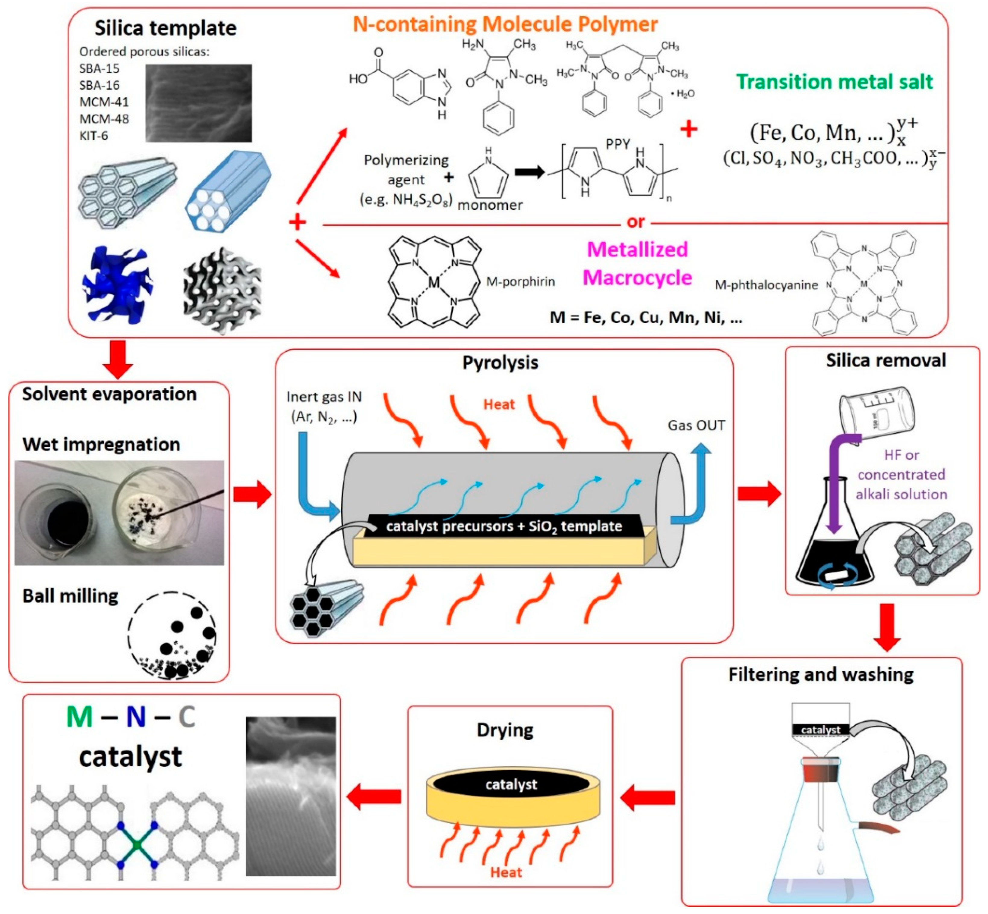
The idea behind this synthesis approach is to take advantage of the shape of a template agent, usually porous silica, and negatively replicate its structure by the incorporation of the catalyst precursor(s). After the carbonization process (pyrolysis), to obtain the final catalyst, the silica template is removed by leaching with an appropriate chemical that only reacts with silica and does not damage the M–N–C material. A schematic representation of this synthesis method is shown in Figure 4. The hard template method has been utilized for many different purposes, including obtaining carbon-based materials with controlled porosity, which in turn can be used as carbonaceous support materials to produce M–N–C catalysts, using Methods 1 and 2. To produce these ordered porous carbon-based materials, different methods were used, such as impregnation of C-precursor (e.g., sucrose) [114], polymerization of the precursor on the support [115], spray pyrolysis [116].
Unlike in Methods 1 and 2, the main advantage of Method 3 is the possibility to avoid the use of a carbon support, since the high surface area and the desired porous structure are induced by the structure of the hard template used.
Of course, one of the most important parameters to consider in this type of synthesis is the porous silica to be used, since it affects strongly the morphology and porosity of the final catalyst. Different types of silica have been used to properly tune the catalyst towards the desired features. Laboratory-made silica (e.g., SBA-15, SBA-16, KIT-6, MCM-41, MCM-48) are usually prepared from a solution containing a surfactant (e.g., Pluronic® block copolymer), and tetraethoxysilane (TEOS) used as Si precursor [23,117,118]. The different ordered porous silica can be obtained by varying some synthesis parameters, like reaction temperature and time, surfactant type and concentration in solution, and the TEOS-to-surfactant ratio. After allowing a sufficient time for the TEOS to polymerize and replicate the surfactant structure in the solution, the solvent is evaporated and the silica is finally obtained by subsequent calcination in air atmosphere at high temperature (400–600 °C) to remove the residual surfactant by combustion [117,119]. Different grades of commercially available silica (Cab-O-Sil®, Cabot Corp., Boston, MA, USA), having different surface area, were also used extensively by Atanassov and coworkers [120,121,122]. Several works investigated the effect of the type of silica template on the performance of the M–N–C catalyst, showing the importance of choosing appropriately the template [118,123,124].
As catalysts precursors, different chemicals can be used. N-containing polymers and organic molecules together with metal salts, and N-containing organic molecules forming complexes with metal ions, have been utilized as precursors to prepare catalysts via hard template method. Metallized macrocyclic compounds have been also used in several works, taking advantage of the fact that they can be used as a unique C, N, and metal precursor [123,125,126].
To enable the replica of its structure, the silica template must be somehow mixed with the catalyst precursor(s). The mixing may be done through different methods: solvent evaporation [127], ball milling [124,128], or wet impregnation [23,129]. After this, the pyrolysis heat treatment is done to form the M–Nx/C active sites, as in Methods 1 and 2. The final step of the synthesis is usually the removal of the silica template. This is effectively done by a washing treatment with an HF solution (usually in the concentration of 5–10 wt%). As an alternative, a concentrated alkaline solution (NaOH or KOH) can be used, as reported in some works [115,125,130]. This alternative should be considered especially in those labs where the use of HF is limited or prohibited due to safety issues.
An interesting innovative “soft-template” approach was recently proposed by Mun et al. In this work, the organic N and Fe precursor (a Fe-phenanthroline complex) was mixed in solution with Resol (precursor of a phenol-formaldehyde resin), TEOS, and a surfactant (Pluronic® 127). The silica formation takes place together with the casting, and the catalyst precursor is simultaneously incorporated in the matrix. The H2/O2 fuel cell test provides better results compared to a similar catalyst prepared using the hard template method by wet impregnation on SBA-15 silica [129].
2.4. Method 4: Catalysts Derived from Metal Organic Frameworks (MOFs)
Metal organic frameworks (MOFs) are materials composed of metal ions and organic linkers that, joined together, can form highly ordered crystalline structures, which have the particularity to be porous. The counter ions (negatively charged) that balance the positive charge of the metallic ions are located inside the pores, together with residuals molecules of solvents that can remain trapped during the synthesis process [131]. The possibility to finely tune their structure by appropriately choosing the metal ion and the organic ligand molecule gives MOFs a unique feature: they can be flexibly used to synthesize materials according to a wide range of specific needs [132]. In fact, in the last decade, MOFs have been used for several different applications, including storage of gases (e.g., H2 adsorption) [133], fabrication of proton conducing membranes [131,132], electrocatalytic materials (e.g., for ORR, CO2 reduction) [134,135], separation of gases [132], and energy storage (i.e., Li-ion batteries, supercapacitors) [136].
The use of MOFs as precursors for the synthesis of PGM-free ORR electrocatalysts is relatively recent compared to the synthesis approaches described in the previous sections. Using MOFs to synthesize M–N–C catalytic materials turned out to be very convenient, due to their facile synthesis procedure and to their properties. Indeed, MOFs can be formed by metal ions and N-containing organic ligands, strongly linked in a well-ordered structure, with a high density of coordination sites. The possibility of retaining at least partially this ordered structure after the pyrolysis suggested the idea of using a MOF as a catalyst precursor, with the aim to increase the density of atomically-dispersed M–Nx/C active sites, preventing or limiting to a minimum the agglomeration of the metal into catalytically-inactive particles [137,138].
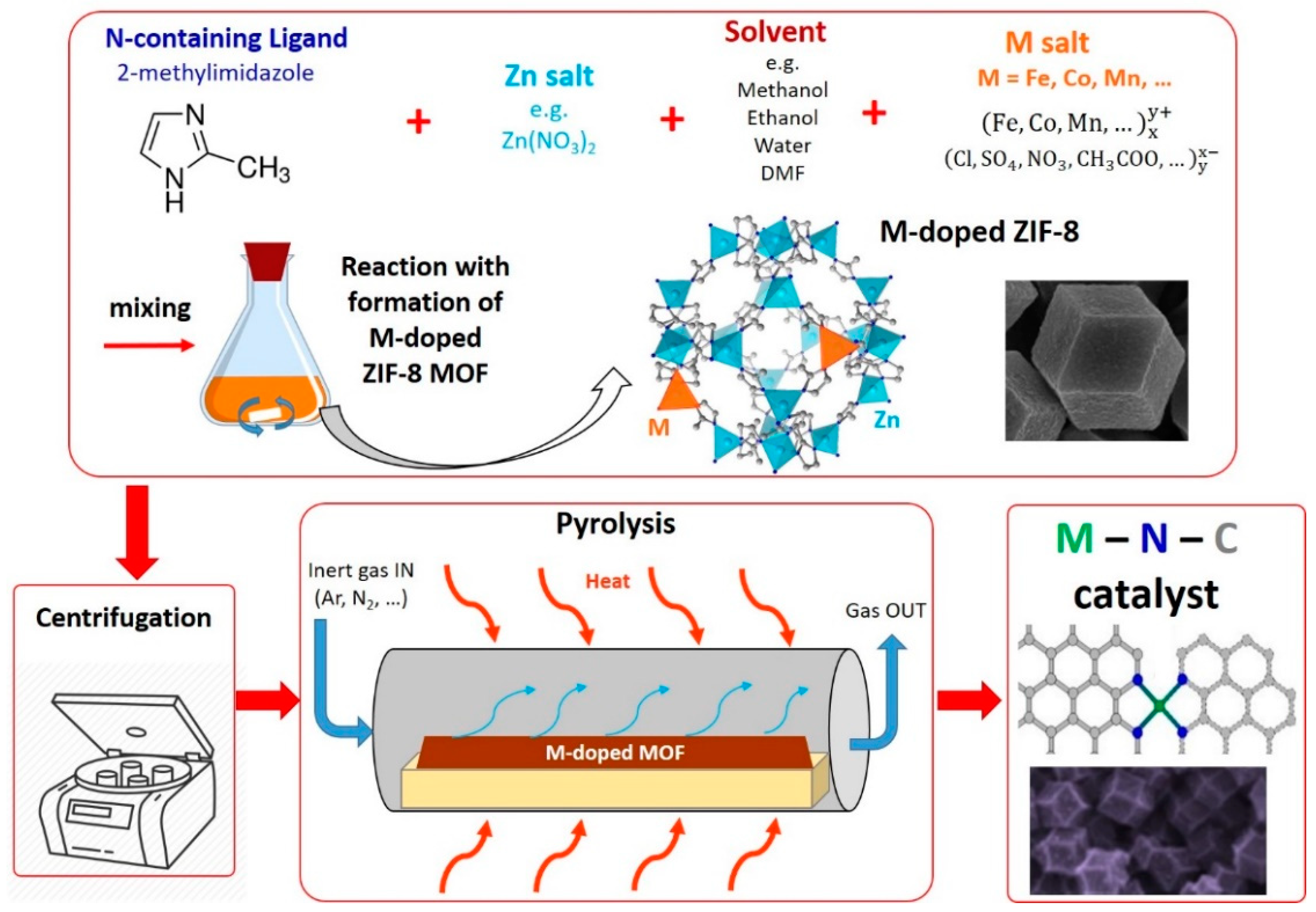
Several recently published comprehensive reviews have extensively described the wide variety of PGM-free catalysts for ORR derived from MOFs [135,139,140]. Here, we will limit the description to a specific focus on the synthesis variables that have been leveraged to tune some of the relevant properties of the MOF-derived catalysts. A representation of a typical synthesis process using MOFs is illustrated in Figure 5.
A particular type of MOF, identified as the Zeolitic Imidazolate Framework (ZIF), is among the most extensively reported for the synthesis of highly-active M–N–C catalysts for ORR. ZIFs contain imidazole-type ligands and transition metals ions coordinated in a tetrahedral structure. For example, one of the most commonly used imidazole-type ligand is 2-mtethylimidazole (MeIm), which can be combined with Zn2+ ions to form the so-called ZIF-8, or with Co2+ ions to form the so-called ZIF-67 [141]. ZIF-7 is produced using Zn2+ ions and benzimidazole as ligand [142]. Lee et al. investigated different synthesis methods to produce ZIF-8: solvothermal using dimethylformamide (DMF) and methanol as solvents, microwave-assisted, sonochemical, mechanochemical (ball milling), dry-gel conversion, and continuous microreactor. All of the methods were effective, and produced ZIF-8 with similar textural properties. However, sonochemical and dry-gel methods produced smaller primary particles, and dry-gel and mechanochemical methods enabled to obtain higher product yields than the others [143].
It was found that pyrolyzing ZIF-8 and ZIF-67 alone does not lead to obtain very active ORR catalysts. In fact, ZIF-8 only contains Zn2+ ions, which are not active to produce ORR catalysts. On the other hand, ZIF-67 contains Co2+ ions that, even though suitable to produce active ORR catalysts, after the pyrolysis result in agglomeration in the form of Co-rich particles This probably happens because Co2+ ions are present in a too high density in the precursor [141,144]. An example of MOF containing only Fe ions was reported by Afsahi and Kaliaguine using 1,3,5-tris(2H-tetrazol-5-yl) benzene hydrochloride as a ligand. After the pyrolysis, the resulting catalysts showed a high content of Fe-rich nanoparticles (carbides, metallic Fe), most likely due to the too high concentration of Fe in the MOF precursor [145], as in the case of pyrolyzed ZIF-67. Another example of MOF containing only Fe ions as metal precursor was reported by Zhao et al. using 2-aminoterephthalic acid as ligand. The latter was only tested in alkaline conditions [146].
Thus, to incorporate a greater number of the highly active Fe–Nx and Co–Nx moieties, taking advantage of the MOF properties, the approach of producing a bimetal MOF was attempted. This approach enabled to obtain improved results compared to using MOFs containing only one metal. In this approach, ZIF-8 is often used as base MOF, since Zn has the beneficial properties of providing high surface area and enhance the microporosity, due to its evaporation during the pyrolysis [135]. The incorporation of the additional active ion (usually Fe or Co) takes place by dissolving a metal salt together with the Zn salt and MeIm to form ZIF-8. In the work of You et al., Co was added in different proportions to substitute Zn in the synthesis of ZIF-8, up to 100% (to obtain ZIF-67). Different pyrolysis temperature were attempted, finding that the most active catalyst was the one synthesized using a molar proportion of Zn:Co = 0.8:0.2, pyrolyzed at 900 °C. This sample showed a higher surface area compared to pyrolyzed ZIF-67 due to the beneficial Zn evaporation effect [147].
MOFs are usually synthesized by dissolving the metal salt and the organic ligand in a suitable solvent, to achieve a complete dissolution of both precursors. Solvents like methanol, ethanol, water, DMF, and N,N’-dimethylacetamide (DMA) have been used [138,141,148,149,150]. Thus, the chemical properties of the solvent and the organic solute, and their relative proportion in the solution, are crucial factors to consider in the synthesis. Additionally, the use of surfactants for the synthesis in aqueous solution was found to be useful, as described in the work of Wang et al. [150]. Here, two surfactants (Span® 80 and TWEEN® 80) were dissolved with MeIm, Fe2+, and Zn2+ ions in water. The surfactants help to prevent OH− ions to bind to Zn2+ to form alkaline salts, enabling the preferential binding with MeIm. In the same work, it was found that carrying out the bimetal MOF synthesis under inert atmosphere rather than under air, enables to increase considerably the ORR activity and selectivity towards a complete 4 e− reduction in acidic medium. The catalyst derived from the MOF synthesized under Ar showed a half wave potential (E1/2) of 0.82 V vs. RHE (reversible hydrogen electrode) and almost null H2O2 generation, while its counterpart synthesized under air showed E1/2 = 0.65 V vs. RHE and a molar H2O2 generation between 10 and 20%. The better performance of the catalyst synthesized under inert atmosphere was attributed to the fact that Fe ions remain under the reduced Fe2+ form, while in the presence of O2 they tend to be oxidized to Fe3+. In fact, Fe2+ and Zn2+ ions are isovalent, and the former can more easily homogeneously replace the latter in the ZIF-8 structure without excessive distortion, which happens instead with Fe3+, leading to a less stable configuration. Thus, having Fe2+ helps to generate a more uniform Fe dispersion at atomic level during the pyrolysis, while with Fe3+, catalytically inactive Fe-containing aggregates are formed in larger amount [150].
Another interesting aspect was investigated in the work of Zhang et al. [138]. Here, the authors produced a series of Fe-doped ZIF-8 with a wide range of nanocrystals size (between 20 and 1000 nm) using methanol as solvent. This effect was obtained by varying the molar ratio between Zn2+ and methanol in the solution. The most active catalyst was found to be the one showing a nanocrystal size of 50 nm. The influence of the pyrolysis temperature was also investigated, ranging between 600 and 1100 °C. The catalyst pyrolyzed up to 1100 °C was found to be the most active and the most selective towards 4 e− ORR.
A recently published work from Wu et al. investigated the Co doping amount in ZIF-8. This was done considering that ZIF-67 is isomorphic with ZIF-8, and for this reason, the amount of Co2+ ions substituting Zn2+ can be adjusted with a continuous trend going from 0 (ZIF-8) to 100% (ZIF-67). The optimum activity in RDE was obtained for a Co content of 20%. The influence of the pyrolysis temperature was also investigated, finding that, as in the case of Fe-ZIF, the best activity is obtained by pyrolyzing at 1100 °C [151].
It is worth noting that by using the bimetal MOF approach, the additional treatments (such as acid leaching and second pyrolysis), which were found to be useful to increase the catalysts’ activity in the synthesis approaches described in the previous sections, can usually be avoided [150].
A method to increase the surface area was developed through the introduction of the N-rich ligand 1-H-1,2,3-triazole into the ZIF-8 structure by a solvent-assistant-linker-exchange. This molecule goes through a rapid decomposition during the heat treatment, generating gaseous molecules (i.e., CO2, NO2, NO, HCN, N2), resulting in a higher pore volume surface area compared to the regular ZIF-8 [152]. This strategy could result beneficial in improving the mass transport properties of Fe-Zn and Co-Zn MOF-derived catalysts, even though it has not explored so far.
2.5. Method 5: Catalysts Derived from MOFs and Additional Precursors
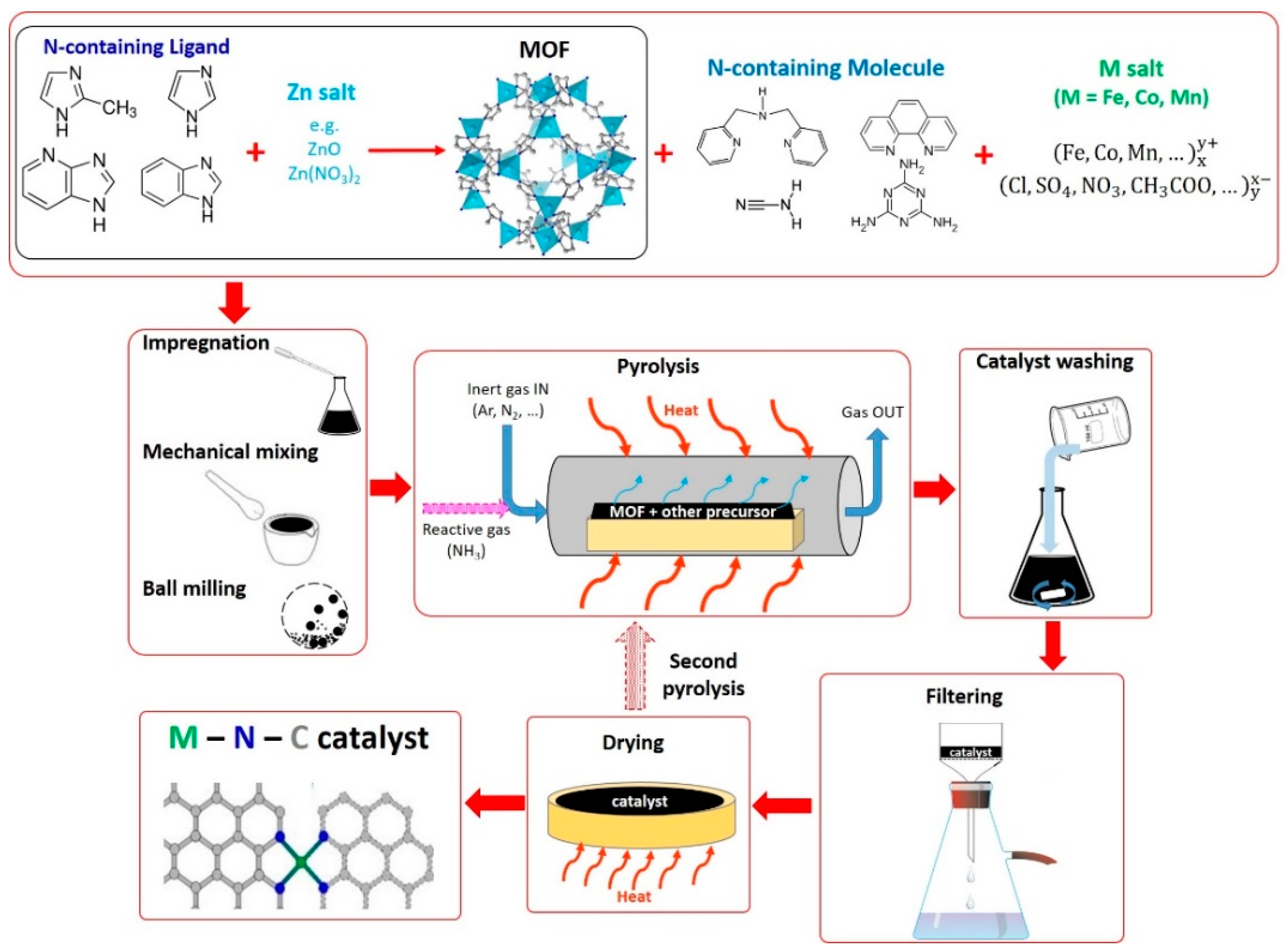
In this method, precursors containing additional sources of N and M are added to ZIF-8 or other Zn-based MOFs. This is an alternative method compared to the bimetal MOF approach, to incorporate Fe, Co, or Mn ions into the MOF-derived catalyst. In fact, since MOFs possess a highly porous structure, it is possible to absorb additional molecules inside their pores. Thus, in this case, we can imagine the MOF acting as the carbon support materials described in Methods 1 and 2. However, unlike carbon supports, which are inactive towards ORR, MOFs can be effectively used as a “host” ordered structured to incorporate the active metal ions into atomically dispersed M–Nx sites after the heat treatment, as described in Method 4 [135]. A schematic representation of this synthesis method is illustrated in Figure 6.
N-containing organic molecules and various metal precursors (e.g., salts) are usually added to ZIF-8 or other Zn-based MOFs to incorporate Fe–Nx, Co–Nx, or Mn–Nx ORR active sites. NH3 can also be used as an additional source of N as pyrolysis gas [153], as in Methods 1 and 2.
In 2011, in one of the first works published utilizing MOF to produce M–N–C catalysts for ORR, a Co-based MOF (ZIF-67) was mixed with piperazine (diethylenediamine), and pyrloyzed at different temperatures between 500 and 900 °C. The sample pyrolyzed at 750 °C showed the best ORR activity in RDE. Doing an acid leaching treatment after the pyrolysis was also found to slightly improve the ORR activity [149].
A particular synthesis method was used by Zhao et al. First, an Fe-imidazolate framework was prepared using ferrocene and imidazole, and then ball milled together with ZIF-8. This mixture was then pyrolyzed first under inert gas and then under NH3 flow [154].
Fe complexes with 1,10-phenanthroline (Fe-phen) have been used extensively as an Fe and N additional precursor in combination with ZIF-8 [153,155,156,157]. A catalyst derived from the incorporation of Fe-phen on ZIF-8 showed higher PEFC performance compared to a counterpart catalyst synthesized incorporating Fe-phen on carbon black (Black Pearls 2000) [158]. In another work, the effect of the type of complex was also investigated, using three different precursors that were added to ZIF-8, and subsequently pyrolyzed. An Fe salt only (Fe(II)acetate), a complex of Fe(II)acetate and 1,10-phenanthroline with molar ratio 1:6, and tris-1,10-phenanthroline Fe(II)perchlorate were examined, the latter showing the best activity in PEFC. This suggests that the coordination strength in the precursor plays an important role in the final catalyst performance [70,159].
A comprehensive work by Zhao et al. investigated the effect of four different ligands (2-methylimidazole, imidazole, 2-ethylimidazole, and 4-azabenzimidazole) in the synthesis of ZIFs using ZnO as Zn precursor, and tris-1,10-phenanthroline Fe(II)perchlorate as an additional N and Fe precursor. Interestingly, unlike the others, the catalyst produced using 2-methylimidazole showed a foam-like structure after the pyrolysis. This was attributed to the highly porous structure of the 2-methylimidazole ZIF precursor. In the PEFC testing, this catalyst was the best performing one, most likely due to enhanced mass transport properties due to the porous structure, despite the 2-ethylimidazole-derived catalyst showed the best RDE performance [160].
Recently, Li et al. published the first work about the development of a Mn-doped ZIF-8 catalyst, showing promising activity in both RDE and PEFC. The catalyst was synthesized in two steps. First, Mn3+ and Zn2+ ions were mixed with MeIm in a DMF solution. Different catalysts were prepared varying the Mn content in the ZIF-8 precursor from 0 to 30%. The different Mn-doped ZIF-8 were then submitted to a first heat treatment under N2 at 1100 °C, an acid leaching step, and a second heat treatment under N2 at 900 °C. The one with an initial Mn content of 20% was found to be the most active in RDE. In the second step, the catalyst was dispersed in a solution containing additional Mn2+ ions in combination with N-containing organic compound, to adsorb more Mn and N the catalyst. After recovering the catalyst by centrifugation, another pyrolysis at 1100 °C under N2 was done. Four different N-containing organic compounds were tested: dipicolylamine, phenanthroline, melamine, and cyanamide, with the catalysts synthesized using cyanamide showing the best RDE performance [161].
An interesting synthesis method was presented in the work of Shui et al., where MOF embedded in polymeric nanofibers were produced by electrospinning a dispersion containing ZIF-8, tris-1,10-phenanthroline Fe(II)-perchlorate in DMF. Polyacrilonitrile and polymethylmethacrilate were also added as a polymeric matrix. The nanofibers were then cured at 200 °C in air, and pyrolyzed at 1000 °C under Ar atmosphere for 1 h. Then, the temperature was decreased to 900 °C, and NH3 was flown for 40–60 min. Finally, the catalyst was acid leached and heat treated again under NH3 at 700 °C for 1 h. When tested in a PEFC, this catalyst showed a much better performance compared to a counterpart catalyst synthesized using a carbon black instead of the polymeric electrospun fibers. This was attributed to the improved mass transport induced by the highly macroporous structure of the nanofibers [156].
The performance of PGM-free based MEAs ready for commercialization in portable power applications was achieved with a catalyst produced using a polyacrylonitrile-polymethacrylic acid copolymer, together with ZIF-8 and Fe powder in a DMF dispersion. After drying under vacuum, the mixture was heat treated in air in a multistep process, followed by a first ball milling, a pyrolysis at 1100 °C under N2, and a second ball milling. Then, the excess Fe was removed via multiple acid leaching. After filtering, vacuum drying, and grinding, a further heat treatment at 700 °C under N2, followed by ball milling, was performed [162].
Another explored approach consists in dispersing the MOF on a carbonaceous support. This is done with the aim to prevent the aggregation of MOF nanocrystals into larger particles, that was observed during the pyrolysis. This caused a decrease in the overall surface area, and consequently, of the number of active sites exposed and available for the ORR [135]. Multi-walled carbon nanotubes functionalized with concentrated acids (HNO3 and/or H2SO4) [163,164], and reduced graphene oxide functionalized with polyvinylpyrrolidone [165], have been used as carbon supports for MOFs. Unfortunately, in these works, the ORR activity of the resulting catalysts was only tested in alkaline medium.
3. Catalysts Performance Analysis and Comparison
One of the most evident factors that affects the ORR performance of an M–N–C catalyst is the metal used in the synthesis. Several transition metals have been utilized for the synthesis. More specifically, if we consider only the fourth period d-block transition metals (from Sc to Zn), the two metals found to be by far the most active are Fe and Co. For this reason, these two metals are also the ones that have been more extensively investigated in the literature. Mn, Ni, Cu, and Cr are also able to provide some ORR activity, but to a lower extent compared to Fe and Co [11,23,110]. Zn does not provide any activity if used alone; however, if used together with another active metal, it is useful to provide desirable features to the catalyst, such as higher surface area and N fixation [22,166].
In recent studies, TGA coupled with mass spectroscopy pointed out how the pyrolysis is associated with the evolution of different gases and concomitant weight loss of the catalyst precursor. The low thermal stability and high volatility may cause the sublimation/evaporation of the N-containing organic precursor before a sufficiently high temperature is reached to form the M–Nx/C sites during the pyrolysis [22,23]. If this happens, a relevant amount of the N-containing molecules will be no more in contact with the carbonaceous support and the metal ions. This may lead to disadvantageous consequences, like a low number of active sites produced, and clustering of the metal in catalytically inactive (or less active) forms (i.e., oxides, carbides, nitrides, metallic), avoiding the formation of atomically dispersed catalysts.
Depending on the precursors used, the resulting catalyst shows different characteristics that influence the ORR activity. The graphitization degree (investigated with different techniques like Raman spectroscopy, XPS, XRD), was reported to influence the catalyst stability. However, less graphitic catalysts have been found to be more active due to the presence of more surface defects which may host more ORR active sites [55]. The graphitization degree is most likely dictated by the structure of the carbon support material (if used), and by the heat treatment process. The catalyst’s surface area and pore size distribution also affect the catalyst performance, since they influence the reagents and products mass transport during fuel cell operation [46].
The aim of the following subsections is to screen and analyze the performance measured in RDE and PEFC (H2/O2 and H2/air) for several M–N–C catalysts reported in the literature in the last decade.
It is important to note that the RDE and PEFC performance data reported here are referred to the beginning of test. Even though in several works the durability of the PGM-free catalysts is assessed in RDE or MEA (or in both systems), analyzing and comparing performance results referred to durability tests is extremely complicated, and could lead to misleading interpretations. In fact, for PGM-free catalysts, a universally recognized and standardized durability testing protocol has not been developed thus far, neither for RDE nor for single PEFC. For example, some of the variables of a durability test that may significantly affect the results are: potential (or current) constant hold or cycling, potential (or current) hold value, potential (or current) hold duration, cycling potential (or current) extremes, type of cycling wave (square or triangular), scan rate, presence of inert or reactive atmosphere in the cell during cycling, and number of cycles. Having available such high number of variables, many different durability protocols have been used by different labs, making the comparison difficult, and the analysis of durability tests results beyond the scope of this review.
Another important aspect to consider when comparing different catalysts is their cost. Nevertheless, it is not easy to provide in this review a comprehensive and detailed analysis. Indeed, all of the works cited in this review, as many others, describe the synthesis of the catalyst carried out at lab scale. From this information, we cannot provide a reliable estimation of a catalyst production cost. In fact, we could only base our calculation on the prices of the reagents purchased at lab scale (order of magnitude of few grams), while a hypothetical industrial production plant would most likely purchase the reagents at the order of magnitude of several hundred kg, or more. In addition, the synthesis steps at lab scale (as reported in Figure 3, Figure 4, Figure 5 and Figure 6 of this review) may be considerably different than at industrial scale, and the process units involved can be considerably different as well, making a fair estimation of the utilities cost difficult. Thus, the scale-up of the synthesis process from lab-scale to industrial scale is not trivial. After all these considerations, it is easy to understand how an attempt of estimate the catalyst production cost based on a lab scale process could lead to meaningless results.
Providing a reliable catalyst cost estimation based on a likely industrial production process is therefore a not trivial task, which would require a big mole of work; this is beyond the scope of this review. However, an interesting tool named CatCost, which could be used to provide such type of estimation, has been developed recently by the Energy Material Network, a consortium of U.S.A. National Laboratories funded by the U.S.A. Department of Energy. CatCost includes several features, such as raw materials pricing, capital and operating production costs for a new-build, dedicated catalyst production plant, and process templates for production of common catalyst types that can enable a reliable catalyst cost estimation [167].
3.1. RDE Performance
For both Pt-based and PGM-free catalysts, RDE is the most utilized method to test the ORR activity [168], most likely because it is fast and allows a high level of reproducibility. When investigating ORR catalysts for PEFC applications, it has to be considered that RDE has important limitations. In fact, it is not an in-device level technique. The electrode is immersed in a liquid electrolyte, where O2 is dissolved, with consequent mass transport limitations occurring even at relatively low overpotentials. For this reason, the measured current densities are usually between 1 and 10 mA·cm−2, depending on the electrode rotation speed, that is usually set between 200 and 3600 rpm (more commonly 900 or 1600 rpm). These current densities are between 1 and 3 orders of magnitude lower than the typical values achieved in a real PEFC operating with O2 or air at the cathode. Thus, the RDE testing conditions are very different compared to a real PEFC system.
In spite of these limitations, RDE remains a robust technique that can be conveniently utilized for a fast initial screening of ORR catalysts activity. If a newly developed catalyst shows a promising performance in RDE, then it has to be tested in a real operating PEFC to confirm its goodness.
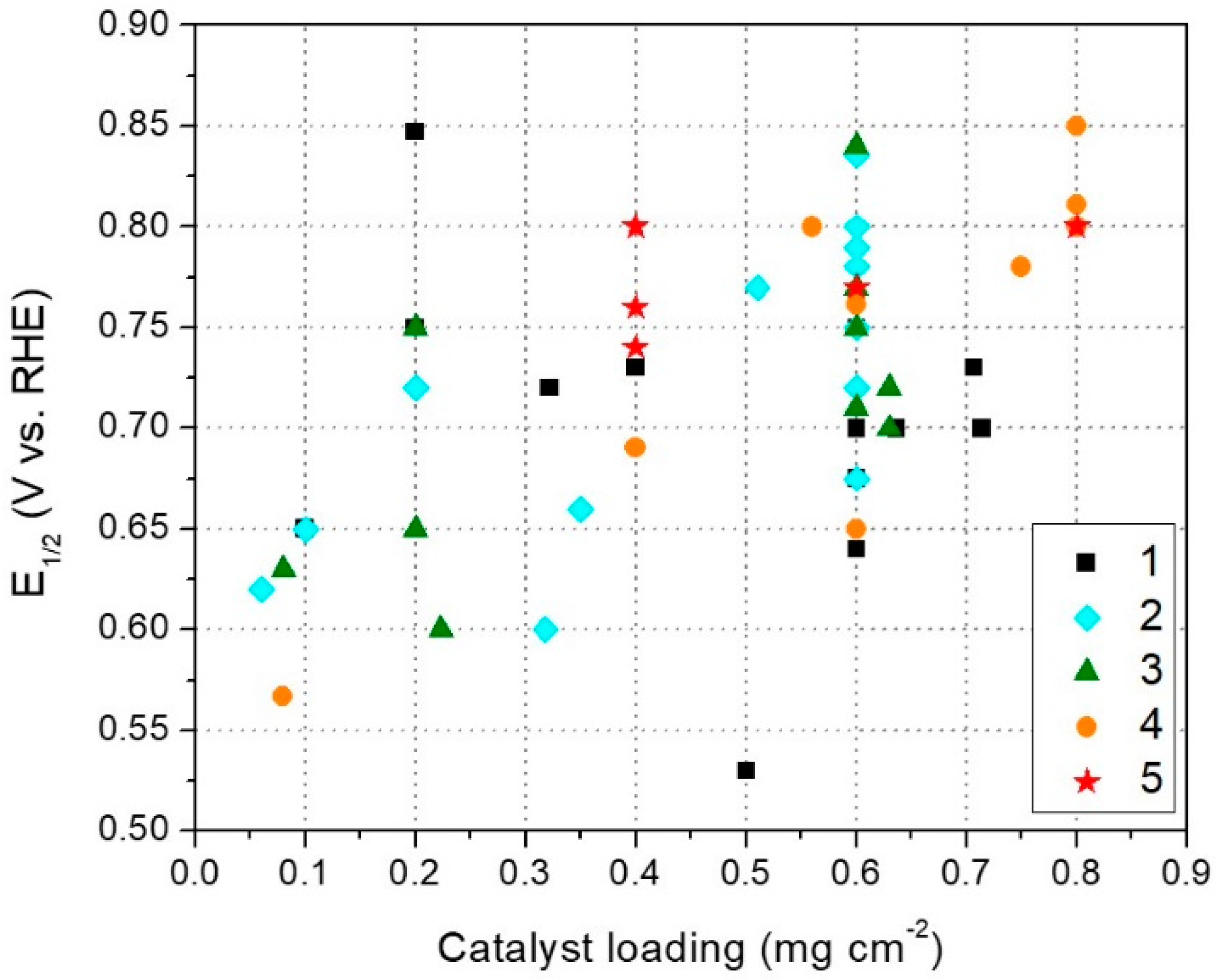
The RDE performances of several catalysts, belonging to all the five different previously discussed synthesis methods, are shown in Figure 7. Here, the performance parameter that has been chosen is the half wave potential (E1/2), universally defined as the potential where half of the maximum current density of a polarization curve is reached. Even if not explicitly reported in all the examined papers, it is easy to extract the E1/2 value from a RDE polarization curve plot. As an alternative, the onset potential (Eon) could have been chosen as the performance parameter. However, Eon definition is more arbitrary. In some works, it has been defined as the potential required to obtain a faradaic current of 0.1 mA cm−2 in a RDE polarization experiment conducted in “static” conditions (staircase voltammetry). However, in other works, the threshold current value could be different, since no standardized definition exists. Moreover, when not explicitly listed in a table or in the text, it is more difficult to extract the Eon value from a simple RDE plot. Also, in many works, the RDE experiments are not conducted in “static” conditions (i.e.,, using the staircase voltammetry technique), but rather by using a linear sweep voltammetry. This makes the Eon extraction even more arbitrary and uncertain, due to the relevant contribution of the capacitive currents at low ORR overpotentials, especially if the ORR polarization curve has not been corrected for the background current measured in the electrolyte saturated with inert gas [169,170,171].
In Figure 7, E1/2 is plotted in function of the catalyst loading deposited on the RDE tip. Table A1 lists all the catalysts plotted in Figure 7, with their respective reference.
From Figure 7, two aspects are immediately evident. First, in the majority of the published papers, the catalyst loading is 0.6 mg·cm−2. Second, there is a general increasing trend of E1/2 with loading. In fact, lower E1/2 values (e.g., below 0.6 V vs. RHE) are mostly obtained with loadings <0.6 mg·cm−2, regardless of the catalyst synthesis method. On the contrary, almost all the high E1/2 values (e.g., above 0.75 V vs. RHE) are obtained with loadings ≥0.6 mg·cm−2. These two aspects are most likely related together In fact, many researchers, during their experiments, could have found that with a loading of 0.6 mg·cm−2 an optimum compromise between loading and performance was achieved. This performance evaluation in function of catalyst loading on RDE tip has been reported in some works [51,172,173]. For this reason, a normalization of the catalyst activity for the loading, or for a parameter indicating the exposed electrode active area (e.g., specific capacitance), is recommended to enable a fairer comparison between RDE test results with different catalyst loadings.
In addition to the increase of ORR performance (i.e.,, Eon and E1/2), it was also found that the H2O2 generation decreases with the loading increase. This happens because on most M–N–C catalysts, ORR may proceed through a path with an intermediate formation of H2O2, which, with a low catalyst loading (i.e., thinner electrode layer) has a higher probability to diffuse into the bulk electrolyte, before being re-adsorbed and reduced to H2O [174], or disproportionate within the catalyst layer [51]. It is important to consider that with these high catalyst loadings on the RDE tip, the validity of the Levich thin electrode model is questionable. Moreover, ORR does not fulfill the assumptions of the Koutecky-Levich method. Thus, the calculation of the number of electrons transferred in ORR via the Koutecky-Levich equation can lead to misleading conclusions [175]. All of these considerations have to be kept in mind when testing M–N–C catalysts in RDE, and when comparing results between different labs.
With all the previous considerations in mind, if we look again to Figure 7, we notice that the catalysts having better RDE performance are generally the ones synthesized with Methods 2, 4, and 5. Only a couple of catalysts synthesized with Method 3, and one catalyst synthesized with Method 1, show E1/2 > 0.75 V vs. RHE, suggesting that MOFs and N-containing polymers precursors are helpful to produce more active ORR catalysts. This can be attributed to a better stabilization of the direct M–N coordination, limiting the coordination bond cleavage during the pyrolysis (with consequent formation of metal-rich catalytically inactive forms), and leading to a higher number of atomically dispersed M–Nx active sites.
Catalysts synthesized with Method 1 showed mostly E1/2 < 0.75. This might be explained by the fact that in Method 1, low molecular weight N-containing organic molecules are used as N precursor. These molecules are more volatile, and consequently, less thermally stable during pyrolysis compared to a polymer or a MOF, thus being less efficient in converting M and N precursors into atomically dispersed M–Nx active sites. The same reasoning can be done for the catalysts obtained with Method 3, which are also synthesized using a low molecular weight N-containing organic molecule. Even though the silica template plays a beneficial role in giving the catalyst a more controlled and tuned morphology (which may improve the mass transport properties), it does not play any role in the “chemistry” of an efficient incorporation of atomically dispersed M–Nx active sites. By concluding, from this analysis, it seems that taking advantage of the properties of MOFs (both “alone” or with additional precursors, i.e., Methods 4 or 5) and polymers (Method 2) is the right path to be followed to get higher ORR activities. Perhaps, focusing on combining MOFs and N-containing polymers can be an effective, still poorly explored, strategy.
Once again, we want to bring the attention to the fact that the data shown in Figure 7 are the beginning of test results. Durability is an important factor to consider for M–N–C catalyst reliability; however, as previously stated, its comparative analysis is made difficult by the high number of different testing protocols that have been used by different labs.
3.2. H2/O2 and H2/Air PEFC Performance
Testing the catalyst in a single H2-fueled acidic membrane PEFC is usually the final step of the development of a new PGM-free catalyst which showed a promising performance in RDE.
In this section, the PEFC performance of several M–N–C catalysts published in the last decade is examined, considering the different synthesis processes used to produce the catalysts, as done for RDE in Section 3.1. The parameter used to evaluate the PEFC performance is the maximum power density reached at beginning of test (initial peak power density, IPPD). IPPD was chosen accordingly to what commonly used in the literature as PEFC performance comparison parameter [40,176].
When comparing the PEFC performances of different PGM-free catalysts, it has to be considered that many factors may have an influence. The MEA fabrication method, in particular regarding the cathode catalyst layer, plays a crucial role in this sense. A careful optimization could be necessary for each different catalyst, taking into account all the variables, such as: ionomer content, catalyst loading, catalyst ink composition (i.e.,, concentration, solvents), ink deposition method (blade coating, spray coating, hand brush painting, etc.), application of the catalyst on the gas diffusion media or on the membrane, hot pressing, type of membrane, type of diffusion media, and compression of the cell. As evident, this careful optimization is a demanding task, and, to the best of our knowledge, no systematic and comprehensive works have been published thus far for PGM-free catalysts. However, for our analysis, we may assume that each research group may have tried to optimize their MEA fabrication method at least at an early stage, before publishing their results. Additionally, the PEFC testing conditions, such as cell temperature, pressure, gas flow rate, and relative humidity, have a strong influence on the IPPD, and should be taken into account when comparing results. Only when keeping in mind all of these aspects we can start out performance comparison analysis.
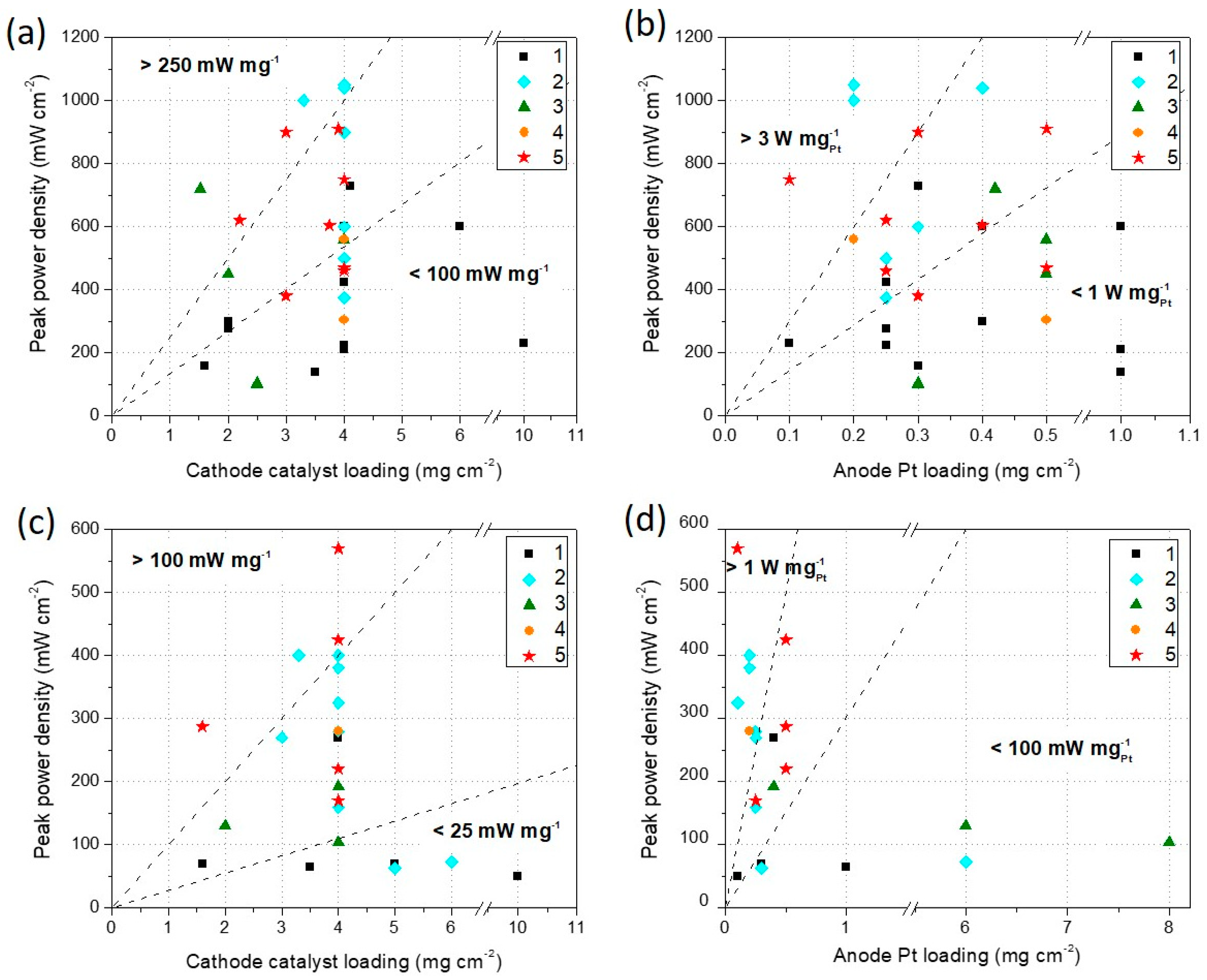
The plots in Figure 8a,b show the IPPD measured in a single H2/O2 PEFC in function of the total M–N–C catalyst loading at the cathode (Figure 8a), and the Pt loading at the anode (Figure 8b).
In Figure 8a, it is evident that in the majority of the works analyzed, the cathode catalyst loading is 4 mg·cm−2. More than a mere coincidence, this may result from a preliminary (and mostly not reported in the papers) optimization done by the authors, or by a recurrent attempt of homologation with the most widely used loading in the literature already published. Among all the parameters listed before, the cathode catalyst loading can be considered as the most relevant MEA fabrication variable related to the catalyst itself, which influences the overall performance. Analyzing the performance in terms of synthesis method, the highest absolute IPPD values (> 600 mW·cm−2) were achieved by the catalysts synthesized with Methods 2 and 5. There are only two exceptions: one for Method 1 and one for Method 3. All the other catalysts synthesized with Methods 1 and 3 show IPPD below 600 mW·cm−2. This trend is similar to what was found in Section 3.1 for RDE tests. The plot area was also divided into three portions, delimited by dotted lines, which represent the specific power densities areas of > 250 mW·mg−1, between 100 and 250 mW·mg−1, and < 100 mW·mg−1. Additionally, in terms of specific power density, Methods 2 and 5 seem to provide the best performances.
In Figure 8b, the IPPD is plotted in function of the anode Pt loading. This parameter may give an indication of the cost of each specific MEA in relation to its absolute performance. The Pt loading is less useful to be related to the overall performance, since in acidic PEFC, the anode is usually not a limiting factor. In fact, the points on the chart are dispersed in a more random way. However, if we look at the specific IPPD (W·mgPt−1) the best results are obtained with Methods 2, 4, and 5, being almost all the catalysts produced with Methods 1 and 3 located in the zone of specific IPPD < 1 W·mgPt−1.
Analogously, the plots in Figure 8c,d show the initial IPPD measured in a single H2/air PEFC in function of the total M–N–C catalyst loading at the cathode (Figure 8c), and the Pt loading at the anode (Figure 8d). The number of papers that show H2/air tests is lower compared to the ones showing H2/O2 tests, as evident comparing the number of points on the plots on Figure 8a,b and Figure 8c,d, and also from Table A2. In spite of this, observing Figure 8c, it is even more evident that the only methods that enable to achieve IPPD > 300 mW·cm−2 are Methods 2 and 5. All the catalysts produced with Methods 1 and 3 (with only one exception) show IPPD < 200 mW·cm−2. Regarding the specific IPPD, values > 100 mW·mg−1 are only obtained with Methods 2 and 5. Figure 8d further confirms the effectiveness of Methods 2, 4, and 5, which are the only ones that enable to overcome the specific IPPD value of 1 W·mgPt−1.
Since the data shown in Figure 8 are referred to beginning of test conditions, it is important to consider that PEFC fabricated using PGM-free catalysts at the cathode have shown so far important durability issues compared to their Pt-based counterparts. The durability of M–N–C catalysts in PEFC has been documented and discussed by several articles and reviews [88,106,155,162,177,178]. However, as previously stated, it is difficult to compare the performance of the different catalysts at the end of durability test, due to the wide variety of durability protocols that were used in the different works. However, it is important to bring the attention of the reader to consider the durability of the M–N–C catalysts, which is still a major issue for the development and consequent large scale utilization of these catalysts in PEFC devices.
For a deeper analysis, we refer the readers interested to this aspect to evaluate the durability behavior of the catalysts shown in Figure 8 by consulting each single reference. In this regard, the catalysts that were submitted to a durability tests in single PEFC are marked in the corresponding column of Table A2.
4. Conclusions and Perspectives
Along several decades of research, a great effort has been put in the development of PEFC with high performance and durability, which finally lead to the commercialization of several types of FCVs. However, the use of Pt as the preferred catalyst in PEFC causes many issues in terms of cost and large scale supply, as pointed out in the Introduction of this review (see Figure 2). Therefore, for several decades, a considerable research effort has also been dedicated to develop PGM-free catalysts for ORR, with remarkable advancements.
In this review, we focused on analyzing specific types of PGM-free catalysts, the M–N–C materials, which have been found to be the most promising in terms of catalytic activity. Several M–N–C catalysts developed in the last decade were reviewed and discussed, with specific focus on the synthesis method. In particular, five different main synthesis methods were identified:
- Method 1: catalysts derived from carbon support and nitrogen containing molecule;
- Method 2: catalysts derived from nitrogen containing polymer;
- Method 3: catalysts derived from silica template and organic precursors (Hard Template Method);
- Method 4: catalysts derived from metal organic frameworks (MOFs);
- Method 5: catalysts derived from MOFs and additional precursors.
Each method showed specific aspects that are worth to be discussed, considering the influence that they may have on the catalyst activity. The subdivision in different categories based on the synthesis method may be helpful for the scientists working in this field, because it gives insights on particular aspects that may deserve a deeper investigation in order to optimize the synthesis process, and achieve better performances. Several patents have been released in the last three years (2016–2018) about M–N–C catalysts development, using all the synthesis methods examined in this review, demonstrating a continuous interest in this research field for industrial applications [179,180,181,182,183,184,185].
Finally, the catalysts performance in RDE and in single H2/O2 and H2/air PEFC were reviewed, and put in relation with the synthesis method used to produce the catalysts. The performance in RDE was also analyzed in function of the catalyst loading on the electrode tip. For PEFC performance, the M–N–C catalyst loading on the cathode, and the Pt loading on the anode were also considered. From the analysis, it can be deduced that the synthesis methods that use MOFs and polymers as catalyst precursors (Methods 2, 4, and 5), lead to obtain the most performing catalysts, suggesting that these are the most promising paths to be pursued for the future development of new PGM-free M–N–C catalysts.
Funding
This research did not receive any specific funding.
Conflicts of Interest
The author declares no conflict of interest.
Appendix A

Table A1.
RDE performance measured in acidic electrolyte for the catalysts reported in Figure 7.
Table A1.
RDE performance measured in acidic electrolyte for the catalysts reported in Figure 7.
| Synthesis Method | E1/2 (V vs. RHE) | Catalyst Loading on RDE Tip (mg·cm−2) | Reference | Durability Test Done |
|---|---|---|---|---|
| 1 | 0.68 | 0.60 | [186] | X |
| 1 | 0.70 | 0.64 | [46] | |
| 1 | 0.73 | 0.40 | [187] | |
| 1 | 0.85 | 0.20 | [84] | X |
| 1 | 0.75 | 0.20 | [188] | X |
| 1 | 0.75 | 0.20 | [189] | |
| 1 | 0.64 | 0.60 | [73] | |
| 1 | 0.65 | 0.10 | [72] | |
| 1 | 0.53 | 0.50 | [47] | X |
| 1 | 0.70 | 0.71 | [79] | |
| 1 | 0.73 | 0.71 | [190] | |
| 1 | 0.72 | 0.32 | [191] | |
| 1 | 0.75 | 0.60 | [77] | |
| 1 | 0.70 | 0.60 | [192] | X |
| 2 | 0.65 | 0.10 | [116] | |
| 2 | 0.60 | 0.32 | [50] | |
| 2 | 0.77 | 0.51 | [36] | X |
| 2 | 0.72 | 0.20 | [94] | |
| 2 | 0.80 | 0.60 | [105] | X |
| 2 | 0.80 | 0.60 | [193] | X |
| 2 | 0.75 | 0.60 | [106] | X |
| 2 | 0.68 | 0.60 | [194] | |
| 2 | 0.80 | 0.60 | [89] | |
| 2 | 0.78 | 0.60 | [91] | |
| 2 | 0.62 | 0.06 | [195] | |
| 2 | 0.72 | 0.60 | [111] | |
| 2 | 0.79 | 0.60 | [108] | X |
| 2 | 0.84 | 0.60 | [100] | |
| 2 | 0.66 | 0.35 | [113] | |
| 3 | 0.77 | 0.60 | [121] | X |
| 3 | 0.65 | 0.20 | [121] | X |
| 3 | 0.60 | 0.22 | [127] | |
| 3 | 0.84 | 0.60 | [123] | X |
| 3 | 0.70 | 0.63 | [22] | X |
| 3 | 0.72 | 0.63 | [126] | |
| 3 | 0.75 | 0.20 | [196] | |
| 3 | 0.71 | 0.60 | [197] | |
| 3 | 0.75 | 0.60 | [128] | |
| 3 | 0.63 | 0.08 | [124] | X |
| 4 | 0.57 | 0.08 | [152] | |
| 4 | 0.80 | 0.56 | [150] | X |
| 4 | 0.85 | 0.80 | [138] | X |
| 4 | 0.81 | 0.80 | [145] | |
| 4 | 0.76 | 0.60 | [147] | X |
| 4 | 0.65 | 0.60 | [149] | |
| 4 | 0.69 | 0.40 | [141] | |
| 4 | 0.78 | 0.75 | [148] | X |
| 4 | 0.80 | 0.80 | [151] | X |
| 5 | 0.80 | 0.80 | [161] | X |
| 5 | 0.80 | 0.40 | [156] | X |
| 5 | 0.76 | 0.40 | [160] | X |
| 5 | 0.77 | 0.60 | [153] | X |
| 5 | 0.74 | 0.40 | [154] |
Table A2.
H2-fueled acidic PEFC performance for the catalysts reported in Figure 8.
Table A2.
H2-fueled acidic PEFC performance for the catalysts reported in Figure 8.
| Synthesis Method | Maximum Power Density H2/O2 (mW·cm−2) | Maximum Power Density H2/Air (mW·cm−2) | Cathode Catalyst Loading (mg·cm−2) | Anode Pt Loading (mg·cm−2) | Reference | Durability Test Done |
|---|---|---|---|---|---|---|
| 1 | 730 | 4.1 | 0.30 | [187] | ||
| 1 | 600 | - | 6.0 | 1.00 | [84] | |
| 1 | 600 | 270 | 4.0 | 0.40 | [189] | X |
| 1 | 230 | 50 | 10.0 | 0.10 | [198] | X |
| 1 | 160 | 70 | 1.6 | 0.30 | [73] | |
| 1 | 300 | - | 2.0 | 0.40 | [80] | X |
| 1 | 210 | - | 4.0 | 1.00 | [79] | X |
| 1 | 225 | - | 4.0 | 0.25 | [190] | X |
| 1 | 140 | 65 | 3.5 | 1.00 | [191] | X |
| 1 | 425 | - | 4.0 | 0.25 | [77] | X |
| 1 | 275 | - | 2.0 | 0.25 | [86] | X |
| 1 | - | 70 | 5.0 | 0.30 | [72] | |
| 2 | 1000 | 400 | 3.3 | 0.20 | [94] | X |
| 2 | 500 | 4.0 | 0.25 | [105] | X | |
| 2 | 900 | 400 | 4.0 | 2.00 | [193] | |
| 2 | 375 | 4.0 | 0.25 | [106] | X | |
| 2 | 600 | 4.0 | 0.30 | [111] | ||
| 2 | 1050 | 380 | 4.0 | 0.20 | [108] | X |
| 2 | 1040 | 4.0 | 0.40 | [100] | X | |
| 2 | 62.5 | 5.0 | 0.30 | [116] | ||
| 2 | 72.5 | 6.0 | 6.00 | [103] | X | |
| 2 | 325 | 4.0 | 0.10 | [36] | X | |
| 2 | 160 | 4.0 | 0.25 | [199] | X | |
| 2 | 270 | 3.0 | 0.25 | [194] | X | |
| 2 | 280 | 4.0 | 0.25 | [89] | X | |
| 3 | 560 | 4.0 | 0.50 | [121] | ||
| 3 | 450 | 2.0 | 0.50 | [200] | X | |
| 3 | 720 | 1.5 | 0.42 | [123] | X | |
| 3 | 100 | 2.5 | 0.30 | [22] | ||
| 3 | 105 | 2.5 | 0.30 | [126] | ||
| 3 | 104 | 4.0 | 8.00 | [127] | X | |
| 3 | 130 | 2.0 | 6.00 | [201] | X | |
| 3 | 192 | 4.0 | 0.40 | [128] | ||
| 4 | 305 | 4.0 | 0.50 | [145] | ||
| 4 | 560 | 280 | 4.0 | 0.20 | [151] | X |
| 5 | 460 | 170 | 4.0 | 0.25 | [161] | X |
| 5 | 900 | 3.0 | 0.30 | [156] | ||
| 5 | 603 | 3.8 | 0.40 | [159] | ||
| 5 | 750 | 570 | 4.0 | 0.10 | [162] | X |
| 5 | 910 | 3.9 | 0.50 | [158] | X | |
| 5 | 620 | 2.2 | 0.25 | [160] | X | |
| 5 | 380 | 3.0 | 0.30 | [153] | X | |
| 5 | 470 | 220 | 4.0 | 0.5 | [202] | X |
| 5 | - | 425 | 4.9 | 0.5 | [155] | X |
| 5 | - | 287 | 1.6 | 0.5 | [154] | X |
References
- Espeland, E.K.; Kettenring, K.M. Strategic plant choices can alleviate climate change impacts: A review. J. Environ. Manag. 2018, 222, 316–324. [Google Scholar] [CrossRef] [PubMed]
- Krajačić, G.; Duić, N.; Zmijarević, Z.; Mathiesen, B.V.; Vučinić, A.A.; Da Graa Carvalho, M. Planning for a 100% independent energy system based on smart energy storage for integration of renewables and CO2 emissions reduction. Appl. Therm. Eng. 2011, 31, 2073–2083. [Google Scholar] [CrossRef]
- Zhu, Y.P.; Guo, C.; Zheng, Y.; Qiao, S.-Z. Surface and Interface Engineering of Noble-Metal-Free Electrocatalysts for Efficient Energy Conversion Processes. Acc. Chem. Res. 2017, 50, 915–923. [Google Scholar] [CrossRef] [PubMed]
- Coralli, A.; Sarruf, B.J.M.; de Miranda, P.E.V.; Osmieri, L.; Specchia, S.; Minh, N.Q. Fuel Cells. In Science and Engineering of Hydrogen-Based Energy Technologies; de Miranda, P.E.V., Ed.; Elsevier: Amsterdam, The Netherlands, 2018; ISBN 9780128142516. [Google Scholar]
- Lemke, C.; Grueger, F.; Arnhold, O. MELY: Market Model for Water Electrolysis—Electrolysis’ Economic Potential given its Technological Feasibility. Energy Procedia 2015, 73, 59–68. [Google Scholar] [CrossRef]
- Speers, P. Hydrogen Mobility Europe (H2ME): Vehicle and Hydrogen Refuelling Station Deployment Results. World Electr. Veh. J. 2018, 1. [Google Scholar] [CrossRef]
- EG&G Technical Services, Inc. Fuel Cell Handbook, 7th ed.; U.S. Department of Energy: Morgantown, WV, USA, 2004.
- Vignarooban, K.; Lin, J.; Arvay, A.; Kolli, S.; Kruusenberg, I.; Tammeveski, K.; Munukutla, L.; Kannan, A.M. Nano-electrocatalyst materials for low temperature fuel cells: A review. Chin. J. Catal. 2015, 36, 458–472. [Google Scholar] [CrossRef]
- Durst, J.; Simon, C.; Hasche, F.; Gasteiger, H.A. Hydrogen Oxidation and Evolution Reaction Kinetics on Carbon Supported Pt, Ir, Rh, and Pd Electrocatalysts in Acidic Media. J. Electrochem. Soc. 2014, 162, F190–F203. [Google Scholar] [CrossRef] [Green Version]
- Sebastián, D.; Serov, A.; Artyushkova, K.; Gordon, J.; Atanassov, P.; Aricò, A.S.; Baglio, V. High Performance and Cost-Effective Direct Methanol Fuel Cells: Fe-N-C Methanol-Tolerant Oxygen Reduction Reaction Catalysts. ChemSusChem 2016, 9, 1986–1995. [Google Scholar] [CrossRef]
- Johnson Matthey. Available online: http://www.platinum.matthey.com/prices (accessed on 27 November 2018).
- US Geological Survey © Statista 2018. Available online: https://www.statista.com/statistics/273645/global-mine-production-of-platinum/ (accessed on 27 November 2018).
- Kongkanand, A.; Mathias, M.F. The Priority and Challenge of High-Power Performance of Low-Platinum Proton-Exchange Membrane Fuel Cells. J. Phys. Chem. Lett. 2016, 7, 1127–1137. [Google Scholar] [CrossRef]
- Banham, D.; Ye, S. Current Status and Future Development of Catalyst Materials and Catalyst Layers for Proton Exchange Membrane Fuel Cells: An Industrial Perspective. ACS Energy Lett. 2017, 2, 629–638. [Google Scholar] [CrossRef]
- Jaouen, F.; Proietti, E.; Lefèvre, M.; Chenitz, R.; Dodelet, J.-P.; Wu, G.; Chung, H.T.; Johnston, C.M.; Zelenay, P. Recent advances in non-precious metal catalysis for oxygen-reduction reaction in polymer electrolyte fuel cells. Energy Environ. Sci. 2011, 4, 114–130. [Google Scholar] [CrossRef]
- Wilson, A.; Kleen, G.; Papageorgopoulos, D. DOE Hydrogen and Fuel Cells Program Record #17007—Fuel Cell System Cost; 2017. Available online: https://www.hydrogen.energy.gov/pdfs/17007_fuel_cell_system_cost_2017.pdf (accessed on 2 February 2019).
- Li, J.; Jaouen, F. Structure and activity of metal-centered coordination sites in pyrolyzed metal–nitrogen–carbon catalysts for the electrochemical reduction of O2. Curr. Opin. Electrochem. 2018. [Google Scholar] [CrossRef]
- Kramm, U.I.; Lefèvre, M.; Larouche, N.; Schmeisser, D.; Dodelet, J.P. Correlations between mass activity and physicochemical properties of Fe/N/C catalysts for the ORR in PEM fuel cell via 57Fe Mössbauer spectroscopy and other techniques. J. Am. Chem. Soc. 2014, 136, 978–985. [Google Scholar] [CrossRef] [PubMed]
- Jia, Q.; Ramaswamy, N.; Hafiz, H.; Tylus, U.; Strickland, K.; Wu, G.; Barbiellini, B.; Bansil, A.; Holby, E.F.; Zelenay, P.; et al. Experimental Observation of Redox-Induced Fe-N Switching Behavior as a Determinant Role for Oxygen Reduction Activity. ACS Nano 2015, 9, 12496–12505. [Google Scholar] [CrossRef] [PubMed]
- Jasinski, R. A New Fuel Cell Cathode Catalyst. Nature 1964, 201, 1212–1213. [Google Scholar] [CrossRef]
- Kiros, Y. Metal Porphyrins for Oxygen Reduction in PEMFC. Int. J. Electrochem. Sci. 2007, 2, 285–300. [Google Scholar]
- Osmieri, L.; Escudero-Cid, R.; Armandi, M.; Ocón, P.; Monteverde Videla, A.H.A.; Specchia, S. Effects of using two transition metals in the synthesis of non-noble electrocatalysts for oxygen reduction reaction in direct methanol fuel cell. Electrochim. Acta 2018, 266, 220–232. [Google Scholar] [CrossRef]
- Osmieri, L.; Monteverde Videla, A.H.A.; Armandi, M.; Specchia, S. Influence of different transition metals on the properties of Me-N-C (Me = Fe, Co, Cu, Zn) catalysts synthesized using SBA-15 as tubular nano-silica reactor for oxygen reduction reaction. Int. J. Hydrogen Energy 2016, 41, 22570–22588. [Google Scholar] [CrossRef]
- Othman, R.; Dicks, A.L.; Zhu, Z. Non precious metal catalysts for the PEM fuel cell cathode. Int. J. Hydrogen Energy 2012, 37, 357–372. [Google Scholar] [CrossRef]
- Chen, Z.; Higgins, D.; Yu, A.; Zhang, L.; Zhang, J. A review on non-precious metal electrocatalysts for PEM fuel cells. Energy Environ. Sci. 2011, 4, 3167–3192. [Google Scholar] [CrossRef]
- Monteverde Videla, A.H.A.; Osmieri, L.; Specchia, S. Non-noble metal (NNM) catalysts for fuel cells: Tuning the activity by a rational step-by-step single variable evolution. In Electrochemistry of N4 Macrocyclic Metal Complexes: Volume 1: Energy, 2nd ed.; Zagal, J.H., Bedioui, F., Eds.; Springer: Berlin/Heidelberg, Germany, 2016; ISBN 9783319311722. [Google Scholar]
- Xu, J.; Zhao, Y.; Shen, C.; Guan, L. Sulfur- and nitrogen-doped, ferrocene-derived mesoporous carbons with efficient electrochemical reduction of oxygen. ACS Appl. Mater. Interfaces 2013, 5, 12594–12601. [Google Scholar] [CrossRef] [PubMed]
- Li, Q.; Cao, R.; Cho, J.; Wu, G. Nanocarbon electrocatalysts for oxygen reduction in alkaline media for advanced energy conversion and storage. Adv. Energy Mater. 2014, 4. [Google Scholar] [CrossRef]
- Osmieri, L.; Escudero-Cid, R.; Monteverde Videla, A.H.A.; Ocón, P.; Specchia, S. Application of a non-noble Fe-N-C catalyst for oxygen reduction reaction in an alkaline direct ethanol fuel cell. Renew. Energy 2017, 115, 226–237. [Google Scholar] [CrossRef]
- Wei, W.; Tao, Y.; Lv, W.; Su, F.-Y.; Ke, L.; Li, J.; Wang, D.-W.; Li, B.; Kang, F.; Yang, Q.-H. Unusual High Oxygen Reduction Performance in All-Carbon Electrocatalysts. Sci. Rep. 2014, 4, 6289. [Google Scholar] [CrossRef] [PubMed] [Green Version]
- Osmieri, L.; Zafferoni, C.; Wang, L.; MonteverdeVidela, A.H.A.; Lavacchi, A.; Specchia, S. Polypyrrole-Derived Fe-Co-N-C Catalyst for the Oxygen Reduction Reaction: Performance in Alkaline Hydrogen and Ethanol Fuel Cells. ChemElectroChem 2018. [Google Scholar] [CrossRef]
- Li, X.; Popov, B.N.; Kawahara, T.; Yanagi, H. Non-precious metal catalysts synthesized from precursors of carbon, nitrogen, and transition metal for oxygen reduction in alkaline fuel cells. J. Power Sources 2011, 196, 1717–1722. [Google Scholar] [CrossRef]
- Lu, Y.; Wang, L.; Preuß, K.; Qiao, M.; Titirici, M.M.; Varcoe, J.; Cai, Q. Halloysite-derived nitrogen doped carbon electrocatalysts for anion exchange membrane fuel cells. J. Power Sources 2017, 372, 82–90. [Google Scholar] [CrossRef] [Green Version]
- Gottesfeld, S.; Dekel, D.R.; Page, M.; Bae, C.; Yan, Y.; Zelenay, P.; Kim, Y.S. Anion exchange membrane fuel cells: Current status and remaining challenges. J. Power Sources 2018, 375, 170–184. [Google Scholar] [CrossRef]
- Dekel, D.R. Review of cell performance in anion exchange membrane fuel cells. J. Power Sources 2018, 375, 158–169. [Google Scholar] [CrossRef]
- Peng, H.; Mo, Z.; Liao, S.; Liang, H.; Yang, L.; Luo, F.; Song, H.; Zhong, Y.; Zhang, B. High performance Fe- and N- Doped carbon catalyst with graphene structure for oxygen reduction. Sci. Rep. 2013, 3, 1–7. [Google Scholar] [CrossRef]
- Ramaswamy, N.; Mukerjee, S. Influence of inner- and outer-sphere electron transfer mechanisms during electrocatalysis of oxygen reduction in alkaline media. J. Phys. Chem. C 2011, 115, 18015–18026. [Google Scholar] [CrossRef]
- Ramaswamy, N.; Mukerjee, S. Fundamental Mechanistic Understanding of Electrocatalysis of Oxygen Reduction on Pt and Non-Pt Surfaces: Acid versus Alkaline Media. Adv. Phys. Chem. 2012, 2012, 1–17. [Google Scholar] [CrossRef] [Green Version]
- Trogadas, P.; Fuller, T.F.; Strasser, P. Carbon as catalyst and support for electrochemical energy conversion. Carbon 2014, 75, 5–42. [Google Scholar] [CrossRef]
- Shao, M.; Chang, Q.; Dodelet, J.-P.; Chenitz, R. Recent Advances in Electrocatalysts for Oxygen Reduction Reaction. Chem. Rev. 2016, 116, 3594–3657. [Google Scholar] [CrossRef] [PubMed] [Green Version]
- Wang, Y.-J.; Wilkinson, D.P.; Zhang, J. Noncarbon support materials for polymer electrolyte membrane fuel cell electrocatalysts. Chem. Rev. 2011, 111, 7625–7651. [Google Scholar] [CrossRef] [PubMed]
- Wu, J.; Ma, L.; Yadav, R.M.; Yang, Y.; Zhang, X.; Vajtai, R.; Lou, J.; Ajayan, P.M. Nitrogen-Doped Graphene with Pyridinic Dominance as a Highly Active and Stable Electrocatalyst for Oxygen Reduction. ACS Appl. Mater. Interfaces 2015, 7, 14763–14769. [Google Scholar] [CrossRef] [PubMed]
- Liu, M.; Song, Y.; He, S.; Tjiu, W.W.; Pan, J.; Xia, Y.Y.; Liu, T. Nitrogen-doped graphene nanoribbons as efficient metal-free electrocatalysts for oxygen reduction. ACS Appl. Mater. Interfaces 2014, 6, 4214–4222. [Google Scholar] [CrossRef] [PubMed]
- Masa, J.; Zhao, A.; Wei, X.; Muhler, M.; Schuhmann, W. Metal-free catalysts for oxygen reduction in alkaline electrolytes: Influence of the presence of Co, Fe, Mn and Ni inclusions. Electrochim. Acta 2014, 128, 271–278. [Google Scholar] [CrossRef]
- Zhang, C.; Hao, R.; Liao, H.; Hou, Y. Synthesis of amino-functionalized graphene as metal-free catalyst and exploration of the roles of various nitrogen states in oxygen reduction reaction. Nano Energy 2013, 2, 88–97. [Google Scholar] [CrossRef]
- Osmieri, L.; Escudero-Cid, R.; Armandi, M.; Monteverde Videla, A.H.A.; Fierro, J.L.G.; Ocón, P.; Specchia, S. Fe-N/C catalysts for oxygen reduction reaction supported on different carbonaceous materials. Performance in acidic and alkaline direct alcohol fuel cells. Appl. Catal. B Environ. 2017, 205, 637–653. [Google Scholar] [CrossRef]
- Monteverde Videla, A.H.A.; Ban, S.; Specchia, S.; Zhang, L.; Zhang, J. Non-noble Fe–NX electrocatalysts supported on the reduced graphene oxide for oxygen reduction reaction. Carbon 2014, 76, 386–400. [Google Scholar] [CrossRef]
- Tran, T.N.; Song, M.Y.; Kang, T.H.; Samdani, J.; Park, H.Y.; Kim, H.; Jhung, S.H.; Yu, J.S. Iron Phosphide Incorporated into Iron-Treated Heteroatoms-Doped Porous Bio-Carbon as Efficient Electrocatalyst for the Oxygen Reduction Reaction. ChemElectroChem 2018, 5, 1944–1953. [Google Scholar] [CrossRef]
- Martínez Millán, W.; Toledano Thompson, T.; Arriaga, L.; Smit, M.A. Characterization of composite materials of electroconductive polymer and cobalt as electrocatalysts for the oxygen reduction reaction. Int. J. Hydrogen Energy 2009, 34, 694–702. [Google Scholar] [CrossRef]
- Osmieri, L.; Monteverde Videla, A.H.A.; Specchia, S. Optimization of a Fe-N-C electrocatalyst supported on ordered mesoporous carbon functionalized with polypyrrole for oxygen reduction reaction. Int. J. Hydrogen Energy 2016, 41, 19610–19628. [Google Scholar] [CrossRef]
- Jaouen, F.; Dodelet, J.-P. O2 Reduction Mechanism on Non-Noble Metal Catalysts for PEM Fuel Cells. Part I: Experimental Rates of O2 Electroreduction, H2O2 Electroreduction, and H2O2 Disproportionation. J. Phys. Chem. C 2009, 113, 15422–15432. [Google Scholar] [CrossRef]
- Qiao, J.; Xu, L.; Ding, L.; Zhang, L.; Baker, R.; Dai, X.; Zhang, J. Using pyridine as nitrogen-rich precursor to synthesize Co-N-S/C non-noble metal electrocatalysts for oxygen reduction reaction. Appl. Catal. B Environ. 2012, 125, 197–205. [Google Scholar] [CrossRef]
- Matter, P.H.; Zhang, L.; Ozkan, U.S. The role of nanostructure in nitrogen-containing carbon catalysts for the oxygen reduction reaction. J. Catal. 2006, 239, 83–96. [Google Scholar] [CrossRef]
- Subramanian, N.P.; Li, X.; Nallathambi, V.; Kumaraguru, S.P.; Colon-Mercado, H.; Wu, G.; Lee, J.W.; Popov, B.N. Nitrogen-modified carbon-based catalysts for oxygen reduction reaction in polymer electrolyte membrane fuel cells. J. Power Sources 2009, 188, 38–44. [Google Scholar] [CrossRef]
- Jaouen, F.; Charreteur, F.; Dodelet, J.P. Fe-Based Catalysts for Oxygen Reduction in PEMFCs. J. Electrochem. Soc. 2006, 153, A689. [Google Scholar] [CrossRef]
- Lefèvre, M.; Proietti, E.; Jaouen, F.; Dodelet, J.-P. Iron-based catalysts with improved oxygen reduction activity in polymer electrolyte fuel cells. Science 2009, 324, 71–74. [Google Scholar] [CrossRef] [PubMed]
- Jaouen, F.; Marcotte, S.; Dodelet, J.-P.; Lindbergh, G. Oxygen Reduction Catalysts for Polymer Electrolyte Fuel Cells from the Pyrolysis of Iron Acetate Adsorbed on Various Carbon Supports. J. Phys. Chem. B 2003, 107, 1376–1386. [Google Scholar] [CrossRef]
- Schilling, T.; Bron, M. Oxygen reduction at Fe–N-modified multi-walled carbon nanotubes in acidic electrolyte. Electrochim. Acta 2008, 53, 5379–5385. [Google Scholar] [CrossRef]
- Wang, X.; Wang, B.; Zhong, J.; Zhao, F.; Han, N.; Huang, W.; Zeng, M.; Fan, J.; Li, Y. Iron polyphthalocyanine sheathed multiwalled carbon nanotubes: A high-performance electrocatalyst for oxygen reduction reaction. Nano Res. 2016, 9, 1497–1506. [Google Scholar] [CrossRef]
- Osmieri, L.; Monteverde Videla, A.H.A.; Specchia, S. Activity of Co–N multi walled carbon nanotubes electrocatalysts for oxygen reduction reaction in acid conditions. J. Power Sources 2015, 278, 296–307. [Google Scholar] [CrossRef]
- Byon, H.R.; Suntivich, J.; Crumlin, E.J.; Shao-Horn, Y. Fe-N-modified multi-walled carbon nanotubes for oxygen reduction reaction in acid. Phys. Chem. Chem. Phys. 2011, 13, 21437–21445. [Google Scholar] [CrossRef] [PubMed]
- Negro, E.; Monteverde Videla, A.H.A.; Baglio, V.; Aricò, A.S.; Specchia, S.; Koper, G.J.M. Fe–N supported on graphitic carbon nano-networks grown from cobalt as oxygen reduction catalysts for low-temperature fuel cells. Appl. Catal. B Environ. 2015, 166–167, 75–83. [Google Scholar] [CrossRef]
- Byon, H.R.; Suntivich, J.; Shao-Horn, Y. Graphene-Based Non-Noble-Metal Catalysts for Oxygen Reduction Reaction in Acid. Chem. Mater. 2011, 23, 3421–3428. [Google Scholar] [CrossRef]
- Sebastián, D.; Baglio, V.; Sun, S.; Tavares, A.C.; Aricò, A.S. Graphene-supported substoichiometric sodium tantalate as a methanol-tolerant, non-noble-metal catalyst for the electroreduction of oxygen. ChemCatChem 2015, 7, 911–915. [Google Scholar] [CrossRef]
- Tsai, C.-W.; Tu, M.-H.; Chen, C.-J.; Hung, T.-F.; Liu, R.-S.; Liu, W.-R.; Lo, M.-Y.; Peng, Y.-M.; Zhang, L.; Zhang, J.; et al. Nitrogen-doped graphene nanosheet-supported non-precious iron nitride nanoparticles as an efficient electrocatalyst for oxygen reduction. RSC Adv. 2011, 1, 1349. [Google Scholar] [CrossRef]
- Park, J.C.; Choi, C.H. Graphene-derived Fe/Co-N-C catalyst in direct methanol fuel cells: Effects of the methanol concentration and ionomer content on cell performance. J. Power Sources 2017, 358, 76–84. [Google Scholar] [CrossRef]
- Zhang, L.; Kim, J.; Dy, E.; Ban, S.; Tsay, K.C.; Kawai, H.; Shi, Z.; Zhang, J. Synthesis of novel mesoporous carbon spheres and their supported Fe-based electrocatalysts for PEM fuel cell oxygen reduction reaction. Electrochim. Acta 2013, 108, 480–485. [Google Scholar] [CrossRef]
- Monteverde Videla, A.H.A.; Zhang, L.; Kim, J.; Zeng, J.; Francia, C.; Zhang, J.; Specchia, S. Mesoporous carbons supported non-noble metal Fe-N X electrocatalysts for PEM fuel cell oxygen reduction reaction. J. Appl. Electrochem. 2013, 43, 159–169. [Google Scholar] [CrossRef]
- Herrmann, I.; Kramm, U.I.; Fiechter, S.; Bogdanoff, P. Oxalate supported pyrolysis of CoTMPP as electrocatalysts for the oxygen reduction reaction. Electrochim. Acta 2009, 54, 4275–4287. [Google Scholar] [CrossRef]
- Tian, J.; Morozan, A.; Sougrati, M.T.; Lefèvre, M.; Chenitz, R.; Dodelet, J.-P.; Jones, D.; Jaouen, F. Optimized synthesis of Fe/N/C cathode catalysts for PEM fuel cells: A matter of iron-ligand coordination strength. Angew. Chemie Int. Ed. 2013, 52, 6867–6870. [Google Scholar] [CrossRef] [PubMed]
- Velázquez-Palenzuela, A.; Zhang, L.; Wang, L.; Cabot, P.L.; Brillas, E.; Tsay, K.; Zhang, J. Carbon-Supported Fe–N x Catalysts Synthesized by Pyrolysis of the Fe(II)–2,3,5,6-Tetra(2-pyridyl)pyrazine Complex: Structure, Electrochemical Properties, and Oxygen Reduction Reaction Activity. J. Phys. Chem. C 2011, 115, 12929–12940. [Google Scholar] [CrossRef]
- Bezerra, C.W.B.; Zhang, L.; Lee, K.; Liu, H.; Zhang, J.; Shi, Z.; Marques, A.L.B.; Marques, E.P.; Wu, S.; Zhang, J. Novel carbon-supported Fe-N electrocatalysts synthesized through heat treatment of iron tripyridyl triazine complexes for the PEM fuel cell oxygen reduction reaction. Electrochim. Acta 2008, 53, 7703–7710. [Google Scholar] [CrossRef]
- Velázquez-Palenzuela, A.; Zhang, L.; Wang, L.; Cabot, P.L.; Brillas, E.; Tsay, K.; Zhang, J. Fe-Nx/C electrocatalysts synthesized by pyrolysis of Fe(II)-2,3,5,6-tetra(2-pyridyl)pyrazine complex for PEM fuel cell oxygen reduction reaction. Electrochim. Acta 2011, 56, 4744–4752. [Google Scholar] [CrossRef]
- Zhong, L.; Hu, Y.; Cleemann, L.N.; Pan, C.; Sværke, J.; Jensen, J.O.; Li, Q. Encapsulated iron-based oxygen reduction electrocatalysts by high pressure pyrolysis. Int. J. Hydrogen Energy 2017, 42, 22887–22896. [Google Scholar] [CrossRef]
- Zhong, H.; Zhang, H.; Liu, S.; Deng, C.; Wang, M. Nitrogen-enriched carbon from melamine resins with superior oxygen reduction reaction activity. ChemSusChem 2013, 6, 807–812. [Google Scholar] [CrossRef]
- Bayram, E.; Yilmaz, G.; Mukerjee, S. A solution-based procedure for synthesis of nitrogen doped graphene as an efficient electrocatalyst for oxygen reduction reactions in acidic and alkaline electrolytes. Appl. Catal. B Environ. 2016, 192, 26–34. [Google Scholar] [CrossRef]
- Wu, G.; Nelson, M.; Ma, S.; Meng, H.; Cui, G.; Shen, P.K. Synthesis of nitrogen-doped onion-like carbon and its use in carbon-based CoFe binary non-precious-metal catalysts for oxygen-reduction. Carbon 2011, 49, 3972–3982. [Google Scholar] [CrossRef]
- Chung, H.T.; Johnston, C.M.; Artyushkova, K.; Ferrandon, M.; Myers, D.J.; Zelenay, P. Cyanamide-derived non-precious metal catalyst for oxygen reduction. Electrochem. commun. 2010, 12, 1792–1795. [Google Scholar] [CrossRef]
- Choi, C.H.; Lim, H.K.; Chung, M.W.; Park, J.C.; Shin, H.; Kim, H.; Woo, S.I. Long-range electron transfer over graphene-based catalyst for high-performing oxygen reduction reactions: Importance of size, n-doping, and metallic impurities. J. Am. Chem. Soc. 2014, 136, 9070–9077. [Google Scholar] [CrossRef] [PubMed]
- Nallathambi, V.; Leonard, N.; Kothandaraman, R.; Calabrese Barton, S. Nitrogen Precursor Effects in Iron-Nitrogen-Carbon Oxygen Reduction Catalysts. Electrochem. Solid-State Lett. 2011, 14, B55–B58. [Google Scholar] [CrossRef]
- Charreteur, F.; Jaouen, F.; Dodelet, J.P. Iron porphyrin-based cathode catalysts for PEM fuel cells: Influence of pyrolysis gas on activity and stability. Electrochim. Acta 2009, 54, 6622–6630. [Google Scholar] [CrossRef]
- Meng, H.; Larouche, N.; Lefvre, M.; Jaouen, F.; Stansfield, B.; Dodelet, J.P. Iron porphyrin-based cathode catalysts for polymer electrolyte membrane fuel cells: Effect of NH3 and Ar mixtures as pyrolysis gases on catalytic activity and stability. Electrochim. Acta 2010, 55, 6450–6461. [Google Scholar] [CrossRef]
- Zhu, Y.; Zhang, B.; Feng, Z.; Su, D.S. Synthesis-structure-performance correlation for poly(phenylenediamine)s/iron/carbon non-precious metal catalysts for oxygen reduction reaction. Catal. Today 2016, 260, 112–118. [Google Scholar] [CrossRef]
- Shu, C.; Chen, Y.; Yang, X.-D.; Liu, Y.; Chong, S.; Fang, Y.; Liu, Y.; Yang, W.-H. Enhanced Fe dispersion via “pinning” effect of thiocyanate ion on ferric ion in Fe-N-S-doped catalyst as an excellent oxygen reduction reaction electrode. J. Power Sources 2018, 376, 161–167. [Google Scholar] [CrossRef]
- Thompson, S.T.; Wilson, A.R.; Zelenay, P.; Myers, D.J.; More, K.L.; Neyerlin, K.C.; Papageorgopoulos, D. ElectroCat: DOE’s approach to PGM-free catalyst and electrode R&D. Solid State Ionics 2018, 319, 68–76. [Google Scholar] [CrossRef]
- Huang, H.C.; Shown, I.; Chang, S.T.; Hsu, H.C.; Du, H.Y.; Kuo, M.C.; Wong, K.T.; Wang, S.F.; Wang, C.H.; Chen, L.C.; et al. Pyrolyzed cobalt corrole as a potential non-precious catalyst for fuel cells. Adv. Funct. Mater. 2012, 22, 3500–3508. [Google Scholar] [CrossRef]
- Ramavathu, L.N.; Maniam, K.K.; Gopalram, K.; Chetty, R. Effect of pyrolysis temperature on cobalt phthalocyanine supported on carbon nanotubes for oxygen reduction reaction. J. Appl. Electrochem. 2012, 42, 945–951. [Google Scholar] [CrossRef]
- Banham, D.; Ye, S.; Pei, K.; Ozaki, J.; Kishimoto, T.; Imashiro, Y. A review of the stability and durability of non-precious metal catalysts for the oxygen reduction reaction in proton exchange membrane fuel cells. J. Power Sources 2015, 285, 334–348. [Google Scholar] [CrossRef]
- Wu, G.; Johnston, C.M.; Mack, N.H.; Artyushkova, K.; Ferrandon, M.; Nelson, M.; Lezama-Pacheco, J.S.; Conradson, S.D.; More, K.L.; Myers, D.J.; et al. Synthesis–structure–performance correlation for polyaniline–Me–C non-precious metal cathode catalysts for oxygen reduction in fuel cells. J. Mater. Chem. 2011, 21, 11392–11405. [Google Scholar] [CrossRef]
- Pérez-Alonso, F.J.; Salam, M.A.; Herranz, T.; Gómez de la Fuente, J.L.; Al-Thabaiti, S.A.; Basahel, S.N.; Peña, M.A.; Fierro, J.L.G.; Rojas, S. Effect of carbon nanotube diameter for the synthesis of Fe/N/multiwall carbon nanotubes and repercussions for the oxygen reduction reaction. J. Power Sources 2013, 240, 494–502. [Google Scholar] [CrossRef]
- Ferrandon, M.; Kropf, A.J.; Myers, D.J.; Kramm, U.; Bogdanoff, P.; Wu, G.; Johnston, C.M.; Zelenay, P. Multitechnique Characterization of a Polyaniline-Iron-Carbon Oxygen Reduction Catalyst. J. Phys. Chem. C 2012, 116, 16001–16013. [Google Scholar] [CrossRef]
- Wu, G.; More, K.L.; Xu, P.; Wang, H.-L.; Ferrandon, M.; Kropf, A.J.; Myers, D.J.; Ma, S.; Johnston, C.M.; Zelenay, P. A carbon-nanotube-supported graphene-rich non-precious metal oxygen reduction catalyst with enhanced performance durability. Chem. Commun. 2013, 49, 3291. [Google Scholar] [CrossRef] [PubMed]
- Chokai, M.; Taniguchi, M.; Moriya, S.; Matsubayashi, K.; Shinoda, T.; Nabae, Y.; Kuroki, S.; Hayakawa, T.; Kakimoto, M.; Ozaki, J.; et al. Preparation of carbon alloy catalysts for polymer electrolyte fuel cells from nitrogen-containing rigid-rod polymers. J. Power Sources 2010, 195, 5947–5951. [Google Scholar] [CrossRef]
- Chokai, M.; Daidou, T.; Nabae, Y. Development of Pt-Free Carbon-Based Catalyst for PEFC Cathode Prepared from Polyacrylonitrile. ECS Trans. 2014, 64, 261–270. [Google Scholar] [CrossRef]
- Wang, M.; Woo, K.; Lou, T.; Zhai, Y.; Kim, D. Defining catalyst layer ingredients in PEMFC by orthogonal test and C–V method. Int. J. Hydrogen Energy 2005, 30, 381–384. [Google Scholar] [CrossRef]
- Ding, S.-Y.; Wang, W. Covalent organic frameworks (COFs): From design to applications. Chem. Soc. Rev. 2013, 42, 548–568. [Google Scholar] [CrossRef] [PubMed]
- Lu, S.; Jin, Y.; Gu, H.; Zhang, W. Recent development of efficient electrocatalysts derived from porous organic polymers for oxygen reduction reaction. Sci. China Chem. 2017, 60, 999–1006. [Google Scholar] [CrossRef]
- Day, N.U.; Wamser, C.C.; Walter, M.G. Porphyrin polymers and organic frameworks. Polym. Int. 2015, 64, 833–857. [Google Scholar] [CrossRef]
- Wang, Q.; Zhou, Z.Y.; Lai, Y.J.; You, Y.; Liu, J.G.; Wu, X.L.; Terefe, E.; Chen, C.; Song, L.; Rauf, M.; et al. Phenylenediamine-based FeNx/C catalyst with high activity for oxygen reduction in acid medium and its active-site probing. J. Am. Chem. Soc. 2014, 136, 10882–10885. [Google Scholar] [CrossRef] [PubMed]
- Wang, Y.-C.; Lai, Y.-J.; Song, L.; Zhou, Z.-Y.; Liu, J.-G.; Wang, Q.; Yang, X.-D.; Chen, C.; Shi, W.; Zheng, Y.-P.; et al. S-Doping of an Fe/N/C ORR Catalyst for Polymer Electrolyte Membrane Fuel Cells with High Power Density. Angew. Chemie Int. Ed. 2015, 54, 9907–9910. [Google Scholar] [CrossRef] [PubMed]
- Rita Sulub, S.; Martínez Millán, W.; Smit, M.A. Study of the Catalytic Activity for Oxygen Reduction of Polythiophene Modified with Cobalt or Nickel. Int. J. Electrochem. Sci. 2009, 4, 1015–1027. [Google Scholar]
- Millán, W.M.; Smit, M.A. Study of electrocatalysts for oxygen reduction based on electroconducting polymer and nickel. J. Appl. Polym. Sci. 2009, 112, 2959–2967. [Google Scholar] [CrossRef]
- Bashyam, R.; Zelenay, P. A class of non-precious metal composite catalysts for fuel cells. Nature 2006, 443, 63–66. [Google Scholar] [CrossRef] [PubMed]
- Lee, K.; Zhang, L.; Lui, H.; Hui, R.; Shi, Z.; Zhang, J. Oxygen reduction reaction (ORR) catalyzed by carbon-supported cobalt polypyrrole (Co-PPy/C) electrocatalysts. Electrochim. Acta 2009, 54, 4704–4711. [Google Scholar] [CrossRef]
- Wu, G.; More, K.L.; Johnston, C.M.; Zelenay, P. High-performance electrocatalysts for oxygen reduction derived from polyaniline, iron, and cobalt. Science 2011, 332, 443–448. [Google Scholar] [CrossRef] [PubMed]
- Wu, G.; Artyushkova, K.; Ferrandon, M.; Kropf, A.J.; Myers, D.; Zelenay, P. Performance Durability of Polyaniline-derived Non-precious Cathode Catalysts. ECS Trans. 2009, 25, 1299–1311. [Google Scholar] [CrossRef]
- Sha, H.-D.; Yuan, X.; Hu, X.-X.; Lin, H.; Wen, W.; Ma, Z.-F. Effects of Pyrrole Polymerizing Oxidant on the Properties of Pyrolysed Carbon-Supported Cobalt-Polypyrrole as Electrocatalysts for Oxygen Reduction Reaction. J. Electrochem. Soc. 2013, 160, F507–F513. [Google Scholar] [CrossRef]
- Fu, X.; Zamani, P.; Choi, J.Y.; Hassan, F.M.; Jiang, G.; Higgins, D.C.; Zhang, Y.; Hoque, M.A.; Chen, Z. In Situ Polymer Graphenization Ingrained with Nanoporosity in a Nitrogenous Electrocatalyst Boosting the Performance of Polymer-Electrolyte-Membrane Fuel Cells. Adv. Mater. 2017, 29, 1604456. [Google Scholar] [CrossRef] [PubMed]
- Oh, H.-S.; Oh, J.-G.; Roh, B.; Hwang, I.; Kim, H. Development of highly active and stable non-precious oxygen reduction catalysts for PEM fuel cells using polypyrrole and a chelating agent. Electrochem. commun. 2011, 13, 879–881. [Google Scholar] [CrossRef]
- Domínguez, C.; Pérez-Alonso, F.J.; Abdel Salam, M.; Gómez De La Fuente, J.L.; Al-Thabaiti, S.A.; Basahel, S.N.; Peña, M.A.; Fierro, J.L.G.; Rojas, S. Effect of transition metal (M: Fe, Co or Mn) for the oxygen reduction reaction with non-precious metal catalysts in acid medium. Int. J. Hydrogen Energy 2014, 39, 5309–5318. [Google Scholar] [CrossRef]
- Ding, W.; Li, L.; Xiong, K.; Wang, Y.; Li, W.; Nie, Y.; Chen, S.; Qi, X.; Wei, Z. Shape fixing via salt recrystallization: A morphology-controlled approach to convert nanostructured polymer to carbon nanomaterial as a highly active catalyst for oxygen reduction reaction. J. Am. Chem. Soc. 2015, 137, 5414–5420. [Google Scholar] [CrossRef] [PubMed]
- Liu, Q.; Cao, S.; Qiu, Y.; Zhao, L. Bimetallic Fe-Co promoting one-step growth of hierarchical nitrogen- doped carbon nanotubes/nanofibers for highly efficient oxygen reduction reaction. Mater. Sci. Eng. B 2017, 223, 159–166. [Google Scholar] [CrossRef]
- Oh, H.S.; Kim, H. The role of transition metals in non-precious nitrogen-modified carbon-based electrocatalysts for oxygen reduction reaction. J. Power Sources 2012, 212, 220–225. [Google Scholar] [CrossRef]
- Zeng, J.; Francia, C.; Gerbaldi, C.; Dumitrescu, M.A.; Specchia, S.; Spinelli, P. Smart synthesis of hollow core mesoporous shell carbons (HCMSC) as effective catalyst supports for methanol oxidation and oxygen reduction reactions. J. Solid State Electrochem. 2012, 16, 3087–3096. [Google Scholar] [CrossRef]
- Shrestha, S.; Mustain, W.E. Properties of Nitrogen-Functionalized Ordered Mesoporous Carbon Prepared Using Polypyrrole Precursor. J. Electrochem. Soc. 2010, 157, B1665–B1672. [Google Scholar] [CrossRef]
- Liu, H.; Shi, Z.; Zhang, J.; Zhang, L.; Zhang, J. Ultrasonic spray pyrolyzed iron-polypyrrole mesoporous spheres for fuel cell oxygen reduction electrocatalysts. J. Mater. Chem. 2009, 19, 468–470. [Google Scholar] [CrossRef]
- Thielemann, J.P.; Girgsdies, F.; Schlögl, R.; Hess, C. Pore structure and surface area of silica SBA-15: Influence of washing and scale-up. Beilstein J. Nanotechnol. 2011, 2, 110–118. [Google Scholar] [CrossRef] [PubMed]
- Fulvio, P.F.; Jaroniec, M.; Liang, C.; Dai, S. Polypyrrole-Based Nitrogen-Doped Carbon Replicas of SBA-15 and SBA-16 Containing Magnetic Nanoparticles. J. Phys. Chem. C 2008, 112, 13126–13133. [Google Scholar] [CrossRef]
- Zhao, D.; Feng, J.; Huo, Q.; Melosh, N.; Fredrickson, G.H.; Chmelka, B.F.; Stucky, G.D. Triblock Copolymer Syntheses of Mesoporous Silica with Periodic 50 to 300 Angstrom Pores. Science 1998, 279, 548–552. [Google Scholar] [CrossRef] [PubMed]
- Janarthanan, R.; Serov, A.; Kishore, S.; Gamarra, D.A.; Atanassov, P.; Hibbs, M.R.; Herring, A.M. Direct Methanol Anion Exchange Membrane Fuel Cell with a Non-Platinum Group Metal Cathode based on Iron-Aminoantipyrine Catalyst. Electrochim. Acta 2015, 175, 202–208. [Google Scholar] [CrossRef] [Green Version]
- Serov, A.; Artyushkova, K.; Atanassov, P. Fe-N-C Oxygen Reduction Fuel Cell Catalyst Derived from Carbendazim: Synthesis, Structure, and Reactivity. Adv. Energy Mater. 2014, 4, 1301735. [Google Scholar] [CrossRef]
- Serov, A.; Artyushkova, K.; Niangar, E.; Wang, C.; Dale, N.; Jaouen, F.; Sougrati, M.T.; Jia, Q.; Mukerjee, S.; Atanassov, P. Nano-structured non-platinum catalysts for automotive fuel cell application. Nano Energy 2015, 16, 293–300. [Google Scholar] [CrossRef] [Green Version]
- Cheon, J.Y.; Kim, T.; Choi, Y.; Jeong, H.Y.; Kim, M.G.; Sa, Y.J.; Kim, J.; Lee, Z.; Yang, T.-H.; Kwon, K.; et al. Ordered mesoporous porphyrinic carbons with very high electrocatalytic activity for the oxygen reduction reaction. Sci. Rep. 2013, 3, 2715. [Google Scholar] [CrossRef]
- Monteverde Videla, A.H.A.; Osmieri, L.; Armandi, M.; Specchia, S. Varying the morphology of Fe-N-C electrocatalysts by templating Iron Phthalocyanine precursor with different porous SiO2 to promote the Oxygen Reduction Reaction. Electrochim. Acta 2015, 177, 43–50. [Google Scholar] [CrossRef]
- Lee, K.T.; Ji, X.; Rault, M.; Nazar, L.F. Simple synthesis of graphitic ordered mesoporous carbon materials by a solid-state method using metal phthalocyanines. Angew. Chemie Int. Ed. 2009, 48, 5661–5665. [Google Scholar] [CrossRef]
- Osmieri, L.; Escudero-Cid, R.; Monteverde Videla, A.H.A.; Ocón, P.; Specchia, S. Performance of a Fe-N-C catalyst for the oxygen reduction reaction in direct methanol fuel cell: Cathode formulation optimization and short-term durability. Appl. Catal. B Environ. 2017, 201, 253–265. [Google Scholar] [CrossRef]
- Ziegelbauer, J.M.; Olson, T.S.; Pylypenko, S.; Alamgir, F.; Jaye, C.; Atanassov, P.; Mukerjee, S. Direct spectroscopic observation of the structural origin of peroxide generation from Co-based pyrolyzed porphyrins for ORR applications. J. Phys. Chem. C 2008, 112, 8839–8849. [Google Scholar] [CrossRef]
- Serov, A.; Artyushkova, K.; Andersen, N.I.; Stariha, S.; Atanassov, P. Original Mechanochemical Synthesis of Non-Platinum Group Metals Oxygen Reduction Reaction Catalysts Assisted by Sacrificial Support Method. Electrochim. Acta 2015, 179, 154–160. [Google Scholar] [CrossRef]
- Mun, Y.; Kim, M.J.; Park, S.A.; Lee, E.; Ye, Y.; Lee, S.; Kim, Y.T.; Kim, S.; Kim, O.H.; Cho, Y.H.; et al. Soft-template synthesis of mesoporous non-precious metal catalyst with Fe-Nx/C active sites for oxygen reduction reaction in fuel cells. Appl. Catal. B Environ. 2018, 222, 191–199. [Google Scholar] [CrossRef]
- Jun, S.; Joo, S.H.; Ryoo, R.; Kruk, M.; Jaroniec, M.; Liu, Z.; Ohsuna, T.; Terasaki, O. Synthesis of New, Nanoporous Carbon with Hexagonally Ordered Mesostructure. J. Am. Chem. Soc. 2000, 122, 10712–10713. [Google Scholar] [CrossRef]
- Ren, Y.; Chia, G.H.; Gao, Z. Metal-organic frameworks in fuel cell technologies. Nano Today 2013, 8, 577–597. [Google Scholar] [CrossRef]
- Furukawa, H.; Cordova, K.E.; O’Keeffe, M.; Yaghi, O.M. The chemistry and applications of metal-organic frameworks. Science 2013, 341, 1230444. [Google Scholar] [CrossRef] [PubMed]
- Lee, C.-H.; Filler, R.; Lee, J.; Li, J.; Mandal, B.K. Synthesis and hydrogen adsorption properties of a new phthalocyanine-based metal–organic framework. Renew. Energy 2010, 35, 1592–1595. [Google Scholar] [CrossRef]
- Kornienko, N.; Zhao, Y.; Kley, C.S.; Zhu, C.; Kim, D.; Lin, S.; Chang, C.J.; Yaghi, O.M.; Yang, P. Metal-Organic Frameworks for Electrocatalytic Reduction of Carbon Dioxide. J. Am. Chem. Soc. 2015, 137, 14129–14135. [Google Scholar] [CrossRef] [PubMed]
- Zhang, H.; Osgood, H.; Xie, X.; Shao, Y.; Wu, G. Engineering nanostructures of PGM-free oxygen-reduction catalysts using metal-organic frameworks. Nano Energy 2017, 31, 331–350. [Google Scholar] [CrossRef]
- Zhao, Y.; Song, Z.; Li, X.; Sun, Q.; Cheng, N.; Lawes, S.; Sun, X. Metal Organic Frameworks for Energy Storage and Conversion. Energy Storage Mater. 2015, 2, 35–62. [Google Scholar] [CrossRef]
- Wu, G. Current challenge and perspective of PGM-free cathode catalysts for PEM fuel cells. Front. Energy 2017, 11, 286–298. [Google Scholar] [CrossRef]
- Zhang, H.; Hwang, S.; Wang, M.; Feng, Z.; Karakalos, S.; Luo, L.; Qiao, Z.; Xie, X.; Wang, C.; Su, D.; et al. Single Atomic Iron Catalysts for Oxygen Reduction in Acidic Media: Particle Size Control and Thermal Activation. J. Am. Chem. Soc. 2017, 139, 14143–14149. [Google Scholar] [CrossRef] [PubMed]
- Yang, L.; Zeng, X.; Wang, W.; Cao, D. Recent Progress in MOF-Derived, Heteroatom-Doped Porous Carbons as Highly Efficient Electrocatalysts for Oxygen Reduction Reaction in Fuel Cells. Adv. Funct. Mater. 2018, 28, 1–21. [Google Scholar] [CrossRef]
- Barkholtz, H.M.; Liu, D.-J. Advancements in rationally designed PGM-free fuel cell catalysts derived from metal–organic frameworks. Mater. Horizons 2017, 4, 20–37. [Google Scholar] [CrossRef]
- Xia, W.; Zhu, J.; Guo, W.; An, L.; Xia, D.; Zou, R. Well-defined carbon polyhedrons prepared from nano metal-organic frameworks for oxygen reduction. J. Mater. Chem. A 2014, 2, 11606–11613. [Google Scholar] [CrossRef]
- Park, K.S.; Ni, Z.; Cote, A.P.; Choi, J.Y.; Huang, R.; Uribe-Romo, F.J.; Chae, H.K.; O’Keeffe, M.; Yaghi, O.M. Exceptional chemical and thermal stability of zeolitic imidazolate frameworks. Proc. Natl. Acad. Sci. USA 2006, 103, 10186–10191. [Google Scholar] [CrossRef] [PubMed] [Green Version]
- Lee, Y.R.; Jang, M.S.; Cho, H.Y.; Kwon, H.J.; Kim, S.; Ahn, W.S. ZIF-8: A comparison of synthesis methods. Chem. Eng. J. 2015, 271, 276–280. [Google Scholar] [CrossRef]
- Wang, X.; Fan, X.; Lin, H.; Fu, H.; Wang, T.; Zheng, J.; Li, X. An efficient Co-N-C oxygen reduction catalyst with highly dispersed Co sites derived from a ZnCo bimetallic zeolitic imidazolate framework. RSC Adv. 2016, 6, 37965–37973. [Google Scholar] [CrossRef]
- Afsahi, F.; Kaliaguine, S. Non-precious electrocatalysts synthesized from metal-organic frameworks. J. Mater. Chem. A 2014, 2, 12270–12279. [Google Scholar] [CrossRef]
- Zhao, S.; Yin, H.; Du, L.; He, L.; Zhao, K.; Chang, L.; Yin, G.; Zhao, H.; Liu, S.; Tang, Z. Carbonized nanoscale metal-organic frameworks as high performance electrocatalyst for oxygen reduction reaction. ACS Nano 2014, 8, 12660–12668. [Google Scholar] [CrossRef] [PubMed]
- You, B.; Jiang, N.; Sheng, M.; Drisdell, W.S.; Yano, J.; Sun, Y. Bimetal-Organic Framework Self-Adjusted Synthesis of Support-Free Nonprecious Electrocatalysts for Efficient Oxygen Reduction. ACS Catal. 2015, 5, 7068–7076. [Google Scholar] [CrossRef]
- Liu, T.; Zhao, P.; Hua, X.; Luo, W.; Chen, S.; Cheng, G. An Fe-N-C hybrid electrocatalyst derived from a bimetal-organic framework for efficient oxygen reduction. J. Mater. Chem. A 2016, 4, 11357–11364. [Google Scholar] [CrossRef]
- Ma, S.; Goenaga, G.A.; Call, A.V.; Liu, D.J. Cobalt imidazolate framework as precursor for oxygen reduction reaction electrocatalysts. Chem. A Eur. J. 2011, 17, 2063–2067. [Google Scholar] [CrossRef] [PubMed]
- Wang, X.; Zhang, H.; Lin, H.; Gupta, S.; Wang, C.; Tao, Z.; Fu, H.; Wang, T.; Zheng, J.; Wu, G.; et al. Directly Converting Fe–doped Metal-Organic Frameworks into Highly Active and Stable Fe–N-C Catalysts for Oxygen Reduction in Acid. Nano Energy 2016, 25, 110–119. [Google Scholar] [CrossRef]
- Wang, X.X.; Cullen, D.A.; Pan, Y.-T.; Hwang, S.; Wang, M.; Feng, Z.; Wang, J.; Engelhard, M.H.; Zhang, H.; He, Y.; et al. Nitrogen-Coordinated Single Cobalt Atom Catalysts for Oxygen Reduction in Proton Exchange Membrane Fuel Cells. Adv. Mater. 2018, 30, 1706758. [Google Scholar] [CrossRef] [PubMed]
- Zhao, R.; Xia, W.; Lin, C.; Sun, J.; Mahmood, A.; Wang, Q.; Qiu, B.; Tabassum, H.; Zou, R. A pore-expansion strategy to synthesize hierarchically porous carbon derived from metal-organic framework for enhanced oxygen reduction. Carbon 2017, 114, 284–290. [Google Scholar] [CrossRef]
- Strickland, K.; Miner, E.; Jia, Q.; Tylus, U.; Ramaswamy, N.; Liang, W.; Sougrati, M.-T.; Jaouen, F.; Mukerjee, S. Highly active oxygen reduction non-platinum group metal electrocatalyst without direct metal–nitrogen coordination. Nat. Commun. 2015, 6, 7343. [Google Scholar] [CrossRef] [Green Version]
- Zhao, D.; Shui, J.-L.; Chen, C.; Chen, X.; Reprogle, B.M.; Wang, D.; Liu, D.-J. Iron imidazolate framework as precursor for electrocatalysts in polymer electrolyte membrane fuel cells. Chem. Sci. 2012, 3, 3200–3205. [Google Scholar] [CrossRef]
- Chenitz, R.; Kramm, U.I.; Lefevre, M.; Glibin, V.; Zhang, G.; Sun, S.; Dodelet, J.-P. A specific demetalation of Fe-N4 catalytic sites in the micropores of NC_Ar + NH3 is at the origin of the initial activity loss of this highly active Fe/N/C catalyst used for the reduction of oxygen in PEM fuel cell. Energy Environ. Sci. 2017, 365–382. [Google Scholar] [CrossRef]
- Shui, J.; Chen, C.; Grabstanowicz, L.; Zhao, D.; Liu, D.-J. Highly efficient nonprecious metal catalyst prepared with metal-organic framework in a continuous carbon nanofibrous network. Proc. Natl. Acad. Sci. USA 2015, 112, 10629–10634. [Google Scholar] [CrossRef] [PubMed]
- Li, J.; Jia, Q.; Ghoshal, S.; Liang, W.; Mukerjee, S. Highly Active and Stable Fe-N-C Catalyst for Oxygen Depolarized Cathode Applications. Langmuir 2017, 33, 9246–9253. [Google Scholar] [CrossRef] [PubMed]
- Proietti, E.; Jaouen, F.; Lefèvre, M.; Larouche, N.; Tian, J.; Herranz, J.; Dodelet, J.-P. Iron-based cathode catalyst with enhanced power density in polymer electrolyte membrane fuel cells. Nat. Commun. 2011, 2, 416. [Google Scholar] [CrossRef]
- Barkholtz, H.M.; Chong, L.; Kaiser, Z.B.; Xu, T.; Liu, D.-J. Highly Active Non-PGM Catalysts Prepared from Metal Organic Frameworks. Catalysts 2015, 5, 955–965. [Google Scholar] [CrossRef] [Green Version]
- Zhao, D.; Shui, J.-L.; Grabstanowicz, L.R.; Chen, C.; Commet, S.M.; Xu, T.; Lu, J.; Liu, D.-J. Highly Efficient Non-Precious Metal Electrocatalysts Prepared from One-Pot Synthesized Zeolitic Imidazolate Frameworks. Adv. Mater. 2014, 26, 1093–1097. [Google Scholar] [CrossRef] [PubMed]
- Li, J.; Chen, M.; Cullen, D.A.; Hwang, S.; Wang, M.; Li, B.; Liu, K.; Karakalos, S.; Lucero, M.; Zhang, H.; et al. Atomically dispersed manganese catalysts for oxygen reduction in proton-exchange membrane fuel cells. Nat. Catal. 2018, 1. [Google Scholar] [CrossRef]
- Banham, D.; Kishimoto, T.; Zhou, Y.; Sato, T.; Bai, K.; Ozaki, J.; Imashiro, Y.; Ye, S. Critical advancements in achieving high power and stable nonprecious metal catalyst—Based MEAs for real-world proton exchange membrane fuel cell applications. Sci. Adv. 2018, 4, 1–7. [Google Scholar] [CrossRef] [PubMed]
- Ma, X.; Zhao, X.; Sun, J.; Li, D.; Yang, X. A versatile strategy to fabricate MOFs/carbon material integrations and their derivatives for enhanced electrocatalysis. RSC Adv. 2016, 6, 7728–7735. [Google Scholar] [CrossRef]
- Ge, L.; Yang, Y.; Wang, L.; Zhou, W.; De Marco, R.; Chen, Z.; Zou, J.; Zhu, Z. High activity electrocatalysts from metal-organic framework-carbon nanotube templates for the oxygen reduction reaction. Carbon 2015, 82, 417–424. [Google Scholar] [CrossRef]
- Zhong, H.X.; Wang, J.; Zhang, Y.W.; Xu, W.L.; Xing, W.; Xu, D.; Zhang, Y.F.; Zhang, X.B. ZIF-8 derived graphene-based nitrogen-doped porous carbon sheets as highly efficient and durable oxygen reduction electrocatalysts. Angew. Chemie Int. Ed. 2014, 53, 14235–14239. [Google Scholar] [CrossRef]
- Zelenay, P.; Myers, D. ElectroCat (Electrocatalysis Consortium) DOE Annual Merit Review; 2018. Available online: https://www.hydrogen.energy.gov/pdfs/review18/fc160_myers_2018_o.pdf (accessed on 2 February 2019).
- CatCost—Free and Public Catalyst Cost Estimation Tool. Available online: https://catcost.chemcatbio.org/ (accessed on 20 January 2019).
- Rotating Electrode Methods and Oxygen Reduction Electrocatalysts; Xing, W.; Yin, G.; Zhang, J. (Eds.) Elsevier: Amsterdam, The Netherlands, 2014; ISBN 978-0-444-63278-4. [Google Scholar]
- Frackowiak, E.; Béguin, F. Carbon materials for the electrochemical storage of energy in capacitors. Carbon 2001, 39, 937–950. [Google Scholar] [CrossRef]
- Kim, T.; Lim, S.; Kwon, K.; Hong, S.H.; Qiao, W.; Rhee, C.K.; Yoon, S.H.; Mochida, I. Electrochemical capacitances of well-defined carbon surfaces. Langmuir 2006, 22, 9086–9088. [Google Scholar] [CrossRef] [PubMed]
- Osmieri, L.; Monteverde Videla, A.H.A.; Specchia, S. The use of different types of reduced graphene oxide in the preparation of Fe-N-C electrocatalysts: Capacitive behavior and oxygen reduction reaction activity in alkaline medium. J. Solid State Electrochem. 2016, 20, 3507–3523. [Google Scholar] [CrossRef]
- Chlistunoff, J. RRDE and Voltammetric Study of ORR on Pyrolyzed Fe/Polyaniline Catalyst. On the Origins of Variable Tafel Slopes. J. Phys. Chem. C 2011, 115, 6496–6507. [Google Scholar] [CrossRef]
- Osmieri, L.; Monteverde Videla, A.H.A.; Ocón, P.; Specchia, S. Kinetics of Oxygen Electroreduction on Me-N-C (Me = Fe, Co, Cu) Catalysts in Acidic Medium. Insights on the Effect of the Transition Metal. J. Phys. Chem. C 2017, 121, 17796–17817. [Google Scholar] [CrossRef]
- Bonakdarpour, A.; Lefevre, M.; Yang, R.; Jaouen, F.; Dahn, T.; Dodelet, J.-P.; Dahn, J.R. Impact of Loading in RRDE Experiments on Fe–N–C Catalysts: Two- or Four-Electron Oxygen Reduction? Electrochem. Solid-State Lett. 2008, 11, B105. [Google Scholar] [CrossRef]
- Zhou, R.; Zheng, Y.; Jaroniec, M.; Qiao, S.-Z. Determination of the Electron Transfer Number for the Oxygen Reduction Reaction: From Theory to Experiment. ACS Catal. 2016, 6, 4720–4728. [Google Scholar] [CrossRef]
- Brouzgou, A.; Song, S.Q.; Tsiakaras, P. Low and non-platinum electrocatalysts for PEMFCs: Current status, challenges and prospects. Appl. Catal. B Environ. 2012, 127, 371–388. [Google Scholar] [CrossRef]
- Choi, J.-Y.; Yang, L.; Kishimoto, T.; Fu, X.; Ye, S.; Chen, Z.; Banham, D. Is the rapid initial performance loss of Fe/N/C non precious metal catalysts due to micropore flooding? Energy Environ. Sci. 2017, 10, 296–305. [Google Scholar] [CrossRef]
- Choi, C.H.; Lim, H.K.; Chung, M.W.; Chon, G.; Ranjbar Sahraie, N.; Altin, A.; Sougrati, M.T.; Stievano, L.; Oh, H.S.; Park, E.S.; et al. The Achilles’ heel of iron-based catalysts during oxygen reduction in an acidic medium. Energy Environ. Sci. 2018, 11, 3176–3182. [Google Scholar] [CrossRef]
- Serov, A.; Atanassov, P. Carbendazim-Based Catalytic Materals. U.S. Patent No. US9425464B2, 23 August 2016. [Google Scholar]
- Serov, A.; Atanassov, P. Materials with Atomically Dispersed Chemical Moieties. International Patent No. WO 2016/133921 Al, 25 August 2016. [Google Scholar]
- Calabrese Barton, S.; Ramanujam, K.; Nallathambi, V. Catalyst for Oxygen Reduction Reaction in Fuel Cells. U.S. Patent No. 9,379,388, 28 June 2016. [Google Scholar]
- Armel, V.; Bennet, S.; Jaouen, F.; Jones, D.; Hindocha, S.; Salles, F. Oxygen Reduction Reaction Catalyst. U.S. Patent No. US 2018/0294485 A1, 11 October 2018. [Google Scholar]
- Serov, A.; Atanassov, P.; Halevi, B.; Short, P. Non-PGM Catalyst for Orr Based on Pyrolysed Poly-Complexes. European Patent No. EP 2 906 347 B1, 28 November 2018. [Google Scholar]
- Serov, A.; Halevi, B.; Artyushkova, K.; Atanassov, P.; Martinez, U. Non-PGM Cathode Catalysts for Fuel Cell Application Derived from Heat Treated Heteroatomic Amines Precursors. European Patent No. EP 2 720 793 B1, 20 December 2012. [Google Scholar]
- Imashiro, Y.; Kishimoto, T.; Sato, T.; Ozaki, J.; Maie, T.; Kusadokoro, S. Carbon Catalyst, Electrode, and Battery. U.S. Patent No. 2017/0194653A1, 6 July 2017. [Google Scholar]
- Li, Q.; Wan, G.; Zhao, H.; Pan, L.; Wang, N.; Zhao, W.; Zhou, X.; Cui, X.; Chen, H. Nitrogen-Doped Carbon Vesicles with Dual Iron-Based Sites for Efficient Oxygen Reduction. ChemSusChem 2017, 10, 499–505. [Google Scholar] [CrossRef] [PubMed]
- Yuan, S.; Shui, J.L.; Grabstanowicz, L.; Chen, C.; Commet, S.; Reprogle, B.; Xu, T.; Yu, L.; Liu, D.J. A highly active and support-free oxygen reduction catalyst prepared from ultrahigh-surface-area porous polyporphyrin. Angew. Chemie Int. Ed. 2013, 52, 8349–8353. [Google Scholar] [CrossRef] [PubMed]
- Muthukrishnan, A.; Nabae, Y.; Hayakawa, T.; Okajima, T.; Ohsaka, T. Fe-containing polyimide-based high-performance ORR catalysts in acidic medium: A kinetic approach to study the durability of catalysts. Catal. Sci. Technol. 2015, 5, 475–483. [Google Scholar] [CrossRef]
- Nabae, Y.; Kuang, Y.; Chokai, M.; Ichihara, T.; Isoda, A.; Hayakawa, T.; Aoki, T. High performance Pt-free cathode catalysts for polymer electrolyte membrane fuel cells prepared from widely available chemicals. J. Mater. Chem. A 2014, 2, 11561–11564. [Google Scholar] [CrossRef] [Green Version]
- Vinayan, B.P.; Diemant, T.; Behm, R.J.; Ramaprabhu, S. Iron encapsulated nitrogen and sulfur co-doped few layer graphene as a non-precious ORR catalyst for PEMFC application. RSC Adv. 2015, 5, 66494–66501. [Google Scholar] [CrossRef]
- Maruyama, J.; Hasegawa, T.; Iwasaki, S.; Kanda, H.; Kishimoto, H. Heat treatment of carbonized hemoglobin with ammonia for enhancement of pore development and oxygen reduction activity. ACS Sustain. Chem. Eng. 2014, 2, 493–499. [Google Scholar] [CrossRef]
- Hu, Y.; Jensen, J.O.; Zhang, W.; Martin, S.; Chenitz, R.; Pan, C.; Xing, W.; Bjerrum, N.J.; Li, Q. Fe3C-based oxygen reduction catalysts: Synthesis, hollow spherical structures and applications in fuel cells. J. Mater. Chem. A 2015, 3, 1752–1760. [Google Scholar] [CrossRef]
- Chung, H.T.; Cullen, D.A.; Higgins, D.; Sneed, B.T.; Holby, E.F.; More, K.L.; Zelenay, P. Direct atomic-level insight into the active sites of a high-performance PGM-free ORR catalyst. Science 2017, 357, 479–484. [Google Scholar] [CrossRef] [PubMed]
- Chung, H.T.; Wu, G.; Li, Q.; Zelenay, P. Role of two carbon phases in oxygen reduction reaction on the Co-PPy-C catalyst. Int. J. Hydrogen Energy 2013, 39, 15887–15893. [Google Scholar] [CrossRef]
- Wang, G.; Jiang, K.; Xu, M.; Min, C.; Ma, B.; Yang, X. Short communication A high activity nitrogen-doped carbon catalyst for oxygen reduction reaction derived from polyaniline-iron coordination polymer. J. Power Sources 2014, 266, 222–225. [Google Scholar] [CrossRef]
- Robson, M.H.; Serov, A.; Artyushkova, K.; Atanassov, P. A mechanistic study of 4-aminoantipyrine and iron derived non-platinum group metal catalyst on the oxygen reduction reaction. Electrochim. Acta 2013, 90, 656–665. [Google Scholar] [CrossRef]
- Serov, A.; Robson, M.H.; Smolnik, M.; Atanassov, P. Tri-metallic transition metal–nitrogen–carbon catalysts derived by sacrificial support method synthesis. Electrochim. Acta 2013, 109, 433–439. [Google Scholar] [CrossRef]
- Maruyama, J.; Okamura, J.; Miyazaki, K.; Uchimoto, Y.; Abe, I. Hemoglobin pyropolymer used as a precursor of a noble-metal-free fuel cell cathode catalyst. J. Phys. Chem. C 2008, 112, 2784–2790. [Google Scholar] [CrossRef]
- Ferrandon, M.; Wang, X.; Kropf, A.J.; Myers, D.J.; Wu, G.; Johnston, C.M.; Zelenay, P. Stability of iron species in heat-treated polyaniline–iron–carbon polymer electrolyte fuel cell cathode catalysts. Electrochim. Acta 2013, 110, 282–291. [Google Scholar] [CrossRef]
- Liu, G.; Li, X.; Ganesan, P.; Popov, B.N. Studies of oxygen reduction reaction active sites and stability of nitrogen-modified carbon composite catalysts for PEM fuel cells. Electrochim. Acta 2010, 55, 2853–2858. [Google Scholar] [CrossRef]
- Piela, B.; Olson, T.S.; Atanassov, P.; Zelenay, P. Highly methanol-tolerant non-precious metal cathode catalysts for direct methanol fuel cell. Electrochim. Acta 2010, 55, 7615–7621. [Google Scholar] [CrossRef]
- Larouche, N.; Chenitz, R.; Lefèvre, M.; Proietti, E.; Dodelet, J.P. Activity and stability in proton exchange membrane fuel cells of iron-based cathode catalysts synthesized with addition of carbon fibers. Electrochim. Acta 2014, 115, 170–182. [Google Scholar] [CrossRef]
Figure 1.
(a) Representation of a fuel cell vehicle (FCV) with details of the main components of the propulsion system; (b) schematic picture of a single Polymer Electrolyte Fuel Cell (PEFC).
Figure 1.
(a) Representation of a fuel cell vehicle (FCV) with details of the main components of the propulsion system; (b) schematic picture of a single Polymer Electrolyte Fuel Cell (PEFC).

Figure 2.
(a) Variation of the average monthly price (in US $/troy ounce) of Platinum from July 1992 to September 2018 [14]. (b) Variation of the average monthly price (in US $/troy ounce) of five Platinum Group Metals (PGMs) (Pt, Pd, Rh, Ir, Ru) in the last 5 years (November 2013–November 2018) [14]. (c) Major countries in global mine production of platinum from 2012 to 2017 [15]. (d) Breakdown of the 2017 projected PEFC automotive stack cost at a volume production of 1 k, 100 k, and 500 k systems per year [16].

Figure 3.
Scheme representing the typical steps for the synthesis of M–N–C catalysts with Methods 1 and 2.
Figure 3.
Scheme representing the typical steps for the synthesis of M–N–C catalysts with Methods 1 and 2.

Figure 4.
Scheme representing the typical steps for the synthesis of M–N–C catalysts with Method 3.

Figure 5.
Scheme representing the typical steps for the synthesis of M–N–C catalysts using a pyrolyzed bimetal (Zn + active transition metal M) metal organic framework (Method 4).
Figure 5.
Scheme representing the typical steps for the synthesis of M–N–C catalysts using a pyrolyzed bimetal (Zn + active transition metal M) metal organic framework (Method 4).

Figure 6.
Scheme representing the typical steps for the synthesis of M–N–C catalysts with MOF and additional precursors (Method 5).
Figure 6.
Scheme representing the typical steps for the synthesis of M–N–C catalysts with MOF and additional precursors (Method 5).

Figure 7.
E1/2 measured in a rotating disc electrode (RDE) in acidic electrolyte for M–N–C catalysts synthesized using the five different synthesis methods described in Section 2. See Table A1 for references.

Figure 8.
(a) IPPD in function of cathode M–N–C catalyst loading and (b) IPPD in function of anode Pt loading, for MEAs prepared using different M–N–C catalysts synthesized using the five methods described in Section 2 and tested in single H2/O2 acidic membrane PEFC. (c) IPPD in function of cathode M–N–C catalyst loading and (d) IPPD in function of anode Pt loading, for MEAs prepared using different M–N–C catalysts synthesized using the five methods described in Section 2 and tested in single H2/air acidic PEFC. See Table A2 for references.

© 2019 by the author. Licensee MDPI, Basel, Switzerland. This article is an open access article distributed under the terms and conditions of the Creative Commons Attribution (CC BY) license (http://creativecommons.org/licenses/by/4.0/).
Share and Cite
MDPI and ACS Style
Osmieri, L. Transition Metal–Nitrogen–Carbon (M–N–C) Catalysts for Oxygen Reduction Reaction. Insights on Synthesis and Performance in Polymer Electrolyte Fuel Cells. ChemEngineering 2019, 3, 16. https://doi.org/10.3390/chemengineering3010016
AMA Style
Osmieri L. Transition Metal–Nitrogen–Carbon (M–N–C) Catalysts for Oxygen Reduction Reaction. Insights on Synthesis and Performance in Polymer Electrolyte Fuel Cells. ChemEngineering. 2019; 3(1):16. https://doi.org/10.3390/chemengineering3010016
Chicago/Turabian StyleOsmieri, Luigi. 2019. "Transition Metal–Nitrogen–Carbon (M–N–C) Catalysts for Oxygen Reduction Reaction. Insights on Synthesis and Performance in Polymer Electrolyte Fuel Cells" ChemEngineering 3, no. 1: 16. https://doi.org/10.3390/chemengineering3010016